ss036.l.insulation & vapour sealing of refrigerated pipes...
TRANSCRIPT
Standard Specification No 36
L:\Standard Specifications\SS036.L.Insulation & Vapour Sealing of Refrigerated Pipes & Vessels.doc Page 1 of 29
Insulation and Vapour Sealing of Refrigerated Pipes and Vessels
1.0 Introduction
This specification details Star Refrigeration’s insulation requirements for refrigerated pipework and vessels. It should be used on all projects unless an alternative method is agreed.
The specification has been revised to clarify pipe support details and to revise insulation requirements for external pipework. Painting requirements have also been revised.
The reference ambient conditions are as follows:
Ambient condition 20°C dry bulb, 86% RH, 17.6°C wet bulb for roof voids, corridors and external pipes.
Ambient condition 20°C dry bulb, 80% RH, 16.5°C wet bulb for plant rooms.
These conditions tend to make what we recommend for roof voids, corridors and external pipes slightly more conservative and what we recommend for plant rooms slightly less conservative.
We include the use of 38mm thick insulation where we can. Where two layers are required (at temperatures below –10.0°C) this will be done by using two layers of 19mm thick material.
Section Title 1.0 Introduction 2.0 Insulation Materials 3.0 Preparation 4.0 Insulation 5.0 Application 6.0 Seam Sealant and Glue 7.0 Supports 8.0 Vapour Seal 9.0 Metal Cladding 10.0 Valve Station Insulation and Drip Trays 11.0 Insulation of Miscellaneous Equipment
Appendix 1 Specification Types Appendix 2 Recommended Fire Resistant Insulation Appendix 3 Guidance on Fire Ratings Appendix 4 Suggested Paragraphs for Quotations
Standard Specification No 36
L:\Standard Specifications\SS036.L.Insulation & Vapour Sealing of Refrigerated Pipes & Vessels.doc Page 2 of 29
2.0 Insulation Materials The following materials are specified: Expanded Polystyrene Expanded Polystyrene should be to EPPMA Code – Grade 1 – Self Extinguishing and
shall have minimum density 15kg/m³. Polyurethane
Polyurethane is a rigid section urethane foam and shall have a minimum density of 35kg/m³. Nilflam Nilflam is a fire resistant rigid section PIR (polyisocyanurate) foam and shall have a minimum density of 33kg/m³. Nilflam is a trade name but other PIR materials will not be used without agreement. Phenolic Foam Phenolic foam is manufactured from phelonic resin and shall have a minimum density of 35kg/m3.
Note: Nilflam is our preferred sectional insulating material. Where polystyrene is mentioned in this specification we are referring to expanded polystyrene not extruded polystyrene. Armaflex Armaflex is still used on packaged unit pipework where space is at a premium and where it is relatively warm and there is reasonable air movement. Armaflex must not be used in roof voids except on copper pipe. See SS 065 - Insulation of Low Temperature Steel Piping and Copper Piping with Class O Armaflex Insulation.
2.1 Thermal Conductivity The following thermal conductivities have been assumed:
Material Thermal
Conductivity W/mK
Polystyrene 0.038 Nilflam 0.023 Armaflex 0.035
3.0 Preparation
3.1 Surface Preparation
Carbon Steel Remove loose mill scare, rust, foreign matter and detached paint by scraping and wire brushing to ISO 8501-1 Grade ST2. Sand existing glossy paint and remove grease etc with a degreaser. Stainless Steel As above using stainless steel scrapers and stainless steel wire brushes.
Standard Specification No 36
L:\Standard Specifications\SS036.L.Insulation & Vapour Sealing of Refrigerated Pipes & Vessels.doc Page 3 of 29
3.2 Painting of Carbon Steel and Stainless Steel Apply bitumastic paint to Carbon Steel or anti-chloride barrier paint to Stainless Steel (single coat only, minimum dry film thickness of 80 micron) by brush or roller in accordance with manufacturer’s instructions. Finished appearance shall be smooth and uniform without curtains or runs. The bitumastic paint should be applied by the insulation subcontractor immediately prior to insulation (this is particularly important for vessels or pipework insulated on site – the primer coat will be applied by the piping subcontractor and the single coat of bitumastic paint applied on site by the insulation subcontractor) Note that for insulation applied to oil separators (for heat pumps), bitumastic paint should not be used. A coat of protective primer and a coat of rustoleum combi colour RAL 5010 should be applied.
3.3 Aluminium Foil Protection of Stainless Steel This is an alternative to anti-chloride paint (our preferred method) to protect stainless steel from chlorides in insulation and the air. Apply one layer of aluminium foil, overlapped by at least 50mm and secured with aluminium tape. Finished appearance shall be smooth and uniform without excessive corrugations or wrinkles.
4.0 Insulation
4.1 Insulation Thickness
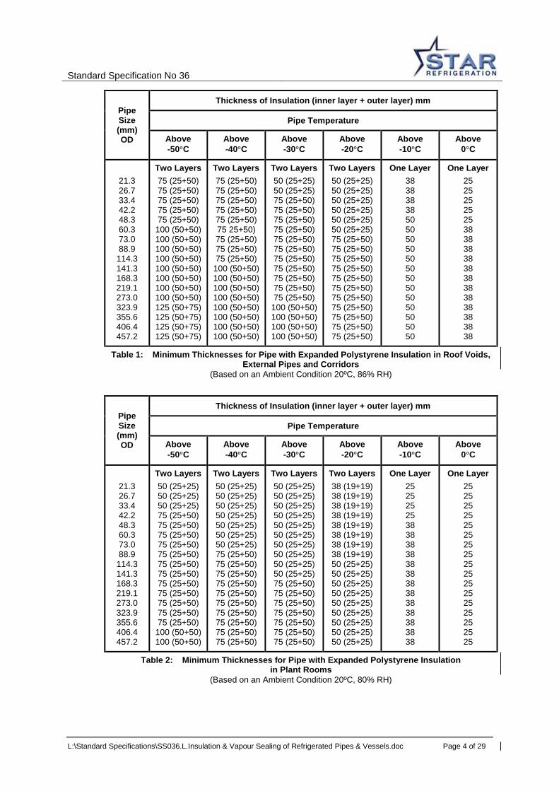
Insulation thicknesses for pipework are given in Tables 1 to 4. Insulation thicknesses for vessels are given in Tables 5 and 6. Tables 1, 2 and 5 cover the use of Polystyrene and Tables 3, 4 and 6 cover the use of Nilflam and Phenolic. For pipes and vessels below -50°C consult the Technical Department. These thicknesses should prevent the insulation surface falling to more than 2.5K below the temperature of the surrounding air. This corresponds to a relative humidity of about 86% in a 20ºC roof void and about 80% in a 20ºC plant room. It is not possible to prevent condensation on insulated pipes and vessels by insulation thickness alone if the relative humidity of the surrounding air rises towards 100% or if there is no air movement over the pipes. Without air movement the air in the vicinity of the pipes will be cooled to its dew point which will result in condensation on the vapour seal. For pipework and vessels operating above -10°C only a single layer of insulation is required. For pipework and vessels operating at -10°C and below at-least two, staggered, layers of insulation are required.
Standard Specification No 36
L:\Standard Specifications\SS036.L.Insulation & Vapour Sealing of Refrigerated Pipes & Vessels.doc Page 4 of 29
Pipe Size (mm) OD
Thickness of Insulation (inner layer + outer layer) mm
Pipe Temperature
Above -50°C
Above -40°C
Above -30°C
Above -20°C
Above -10°C
Above 0°C
21.3 26.7 33.4 42.2 48.3 60.3 73.0 88.9
114.3 141.3 168.3 219.1 273.0 323.9 355.6 406.4 457.2
Two Layers 75 (25+50) 75 (25+50) 75 (25+50) 75 (25+50) 75 (25+50)
100 (50+50) 100 (50+50) 100 (50+50) 100 (50+50) 100 (50+50) 100 (50+50) 100 (50+50) 100 (50+50) 125 (50+75) 125 (50+75) 125 (50+75) 125 (50+75)
Two Layers 75 (25+50) 75 (25+50) 75 (25+50) 75 (25+50) 75 (25+50) 75 25+50) 75 (25+50) 75 (25+50) 75 (25+50)
100 (50+50) 100 (50+50) 100 (50+50) 100 (50+50) 100 (50+50) 100 (50+50) 100 (50+50) 100 (50+50)
Two Layers 50 (25+25) 50 (25+25) 75 (25+50) 75 (25+50) 75 (25+50) 75 (25+50) 75 (25+50) 75 (25+50) 75 (25+50) 75 (25+50) 75 (25+50) 75 (25+50) 75 (25+50)
100 (50+50) 100 (50+50) 100 (50+50) 100 (50+50)
Two Layers 50 (25+25) 50 (25+25) 50 (25+25) 50 (25+25) 50 (25+25) 50 (25+25) 75 (25+50) 75 (25+50) 75 (25+50) 75 (25+50) 75 (25+50) 75 (25+50) 75 (25+50) 75 (25+50) 75 (25+50) 75 (25+50) 75 (25+50)
One Layer 38 38 38 38 50 50 50 50 50 50 50 50 50 50 50 50 50
One Layer 25 25 25 25 25 38 38 38 38 38 38 38 38 38 38 38 38
Table 1: Minimum Thicknesses for Pipe with Expanded Polystyrene Insulation in Roof Voids, External Pipes and Corridors
(Based on an Ambient Condition 20ºC, 86% RH)
Pipe Size (mm) OD
Thickness of Insulation (inner layer + outer layer) mm
Pipe Temperature
Above -50°C
Above -40°C
Above -30°C
Above -20°C
Above -10°C
Above 0°C
21.3 26.7 33.4 42.2 48.3 60.3 73.0 88.9
114.3 141.3 168.3 219.1 273.0 323.9 355.6 406.4 457.2
Two Layers 50 (25+25) 50 (25+25) 50 (25+25) 75 (25+50) 75 (25+50) 75 (25+50) 75 (25+50) 75 (25+50) 75 (25+50) 75 (25+50) 75 (25+50) 75 (25+50) 75 (25+50) 75 (25+50) 75 (25+50)
100 (50+50) 100 (50+50)
Two Layers 50 (25+25) 50 (25+25) 50 (25+25) 50 (25+25) 50 (25+25) 50 (25+25) 50 (25+25) 75 (25+50) 75 (25+50) 75 (25+50) 75 (25+50) 75 (25+50) 75 (25+50) 75 (25+50) 75 (25+50) 75 (25+50) 75 (25+50)
Two Layers 50 (25+25) 50 (25+25) 50 (25+25) 50 (25+25) 50 (25+25) 50 (25+25) 50 (25+25) 50 (25+25) 50 (25+25) 50 (25+25) 75 (25+50) 75 (25+50) 75 (25+50) 75 (25+50) 75 (25+50) 75 (25+50) 75 (25+50)
Two Layers 38 (19+19) 38 (19+19) 38 (19+19) 38 (19+19) 38 (19+19) 38 (19+19) 38 (19+19) 38 (19+19) 50 (25+25) 50 (25+25) 50 (25+25) 50 (25+25) 50 (25+25) 50 (25+25) 50 (25+25) 50 (25+25) 50 (25+25)
One Layer 25 25 25 25 38 38 38 38 38 38 38 38 38 38 38 38 38
One Layer 25 25 25 25 25 25 25 25 25 25 25 25 25 25 25 25 25
Table 2: Minimum Thicknesses for Pipe with Expanded Polystyrene Insulation in Plant Rooms
(Based on an Ambient Condition 20ºC, 80% RH)

Standard Specification No 36
L:\Standard Specifications\SS036.L.Insulation & Vapour Sealing of Refrigerated Pipes & Vessels.doc Page 5 of 29
Pipe Size (mm) OD
Thickness of Insulation (inner layer + outer layer) mm
Pipe Temperature
Above -50°C
Above -40°C
Above -30°C
Above -20°C
Above -10°C
Above 0°C
21.3 26.7 33.4 42.2 48.3 60.3 73.0 88.9
114.3 141.3 168.3 219.1 273.0 323.9 355.6 406.4 457.2
Two Layers 50 (25+25) 50 (25+25) 50 (25+25) 50 (25+25) 50 (25+25) 50 (25+25) 50 (25+25) 75 (25+50) 75 (25+50) 75 (25+50) 75 (25+50) 75 (25+50) 75 (25+50) 75 (25+50) 75 (25+50) 75 (25+50) 75 (25+50)
Two Layers 50 (25+25) 50 (25+25) 50 (25+25) 50 (25+25) 50 (25+25) 50 (25+25) 50 (25+25) 50 (25+25) 75 (25+50) 75 (25+50) 75 (25+50) 75 (25+50) 75 (25+50) 75 (25+50) 75 (25+50) 75 (25+50) 75 (25+50)
Two Layers 50 (25+25) 50 (25+25) 50 (25+25) 50 (25+25) 50 (25+25) 50 (25+25) 50 (25+25) 50 (25+25) 50 (25+25) 50 (25+25) 50 (25+25) 50 (25+25) 50 (25+25) 50 (25+25) 50 (25+25) 50 (25+25) 50 (25+25)
Two Layers 38 (19+19) 38 (19+19) 38 (19+19) 38 (19+19) 38 (19+19) 38 (19+19) 38 (19+19) 38 (19+19) 38 (19+19) 38 (19+19) 38 (19+19) 50 (25+25) 50 (25+25) 50 (25+25) 50 (25+25) 50 (25+25) 50 (25+25)
One Layer 25 25 25 25 25 25 25 25 25 25 25 25 25 38 38 38 38
One Layer 25 25 25 25 25 25 25 25 25 25 25 25 25 25 25 25 25
Table 3: Minimum Thicknesses for Pipe with Nilflam or Phenolic Insulation in Roof Voids, External Pipes and Corridors
(Based on an Ambient Condition 20ºC, 86% RH)
Pipe Size (mm) OD
Thickness of Insulation (inner layer + outer layer) mm
Pipe Temperature
Above -50°C
Above -40°C
Above -30°C
Above -20°C
Above -10°C
Above 0°C
21.3 26.7 33.4 42.2 48.3 60.3 73.0 88.9
114.3 141.3 168.3 219.1 273.0 323.9 355.6 406.4 457.2
Two Layers 50 (25+25) 50 (25+25) 50 (25+25) 50 (25+25) 50 (25+25) 50 (25+25) 50 (25+25) 50 (25+25) 50 (25+25) 50 (25+25) 50 (25+25) 50 (25+25) 50 (25+25) 50 (25+25) 50 (25+25) 50 (25+25) 50 (25+25)
Two Layers 50 (25+25) 50 (25+25) 50 (25+25) 50 (25+25) 50 (25+25) 50 (25+25) 50 (25+25) 50 (25+25) 50 (25+25) 50 (25+25) 50 (25+25) 50 (25+25) 50 (25+25) 50 (25+25) 50 (25+25) 50 (25+25) 50 (25+25)
Two Layers 38 (19+19) 38 (19+19) 38 (19+19) 38 (19+19) 38 (19+19) 38 (19+19) 38 (19+19) 38 (19+19) 38 (19+19) 38 (19+19) 38 (19+19) 38 (19+19) 38 (19+19) 38 (19+19) 38 (19+19) 38 (19+19) 38 (19+19)
Two Layers 38 (19+19) 38 (19+19) 38 (19+19) 38 (19+19) 38 (19+19) 38 (19+19) 38 (19+19) 38 (19+19) 38 (19+19) 38 (19+19) 38 (19+19) 38 (19+19) 38 (19+19) 38 (19+19) 38 (19+19) 38 (19+19) 38 (19+19)
One Layer 25 25 25 25 25 25 25 25 25 25 25 25 25 25 25 25 25
One Layer 25 25 25 25 25 25 25 25 25 25 25 25 25 25 25 25 25
Table 4: Minimum Thicknesses for Pipe with Nilflam or Phenolic Insulation in Plant Rooms (Based on an Ambient Condition 20ºC, 80% RH)

Standard Specification No 36
L:\Standard Specifications\SS036.L.Insulation & Vapour Sealing of Refrigerated Pipes & Vessels.doc Page 6 of 29
Pipe Size (mm) OD
Thickness of Insulation (inner layer + outer layer) mm
Pipe Temperature
Above -50°C
Above -40°C
Above -30°C
Above -20°C
Above -10°C
Above 0°C
355 457 610 762 914
1220 1321 1524 2032
Two Layers 100 (50+50) 100 (50+50) 100 (50+50) 100 (50+50) 100 (50+50) 100 (50+50) 100 (50+50) 100 (50+50) 100 (50+50)
Two Layers 75 (25+50) 75 (25+50) 75 (25+50) 75 (25+50)
100 (50+50) 100 (50+50) 100 (50+50) 100 (50+50) 100 (50+50)
Two Layers 75 (25+50) 75 (25+50) 75 (25+50) 75 (25+50) 75 (25+50) 75 (25+50) 75 (25+50) 75 (25+50) 75 (25+50)
Two Layers 50 (25+25) 50 (25+25) 50 (25+25) 50 (25+25) 50 (25+25) 50 (25+25) 50 (25+25) 50 (25+25) 50 (25+25)
One Layer 38 38 38 38 38 38 38 38 38
One Layer 25(1) 25(1) 25(1) 25(1)
25(1) 25(1) 25(1) 25(1) 25(1)
Table 5: Minimum Thicknesses for Vessel with Expanded Polystyrene
Insulation (Based on an Ambient Condition 20ºC, 80% RH)
Note (1) For these sizes the insulation contractor may choose to use 38mm thick material to leave a sufficient thickness at the vessel supports where the material is thinned to get around the support saddles.
Pipe Size (mm) OD
Thickness of Insulation (inner layer + outer layer) mm
Pipe Temperature
Above -50°C
Above -40°C
Above -30°C
Above -20°C
Above -10°C
Above 0°C
355 457 610 762 914
1220 1321 1524 2032
Two Layers 50 (25+25) 50 (25+25) 50 (25+25) 50 (25+25) 75 (25+50) 75 (25+50) 75 (25+50) 75 (25+50) 75 (25+50)
Two Layers 50 (25+25) 50 (25+25) 50 (25+25) 50 (25+25) 50 (25+25) 75 (25+50) 75 (25+50) 75 (25+50) 75 (25+50)
Two Layers 50 (25+25) (2) 50 (25+25) (2) 50 (25+25) (2) 50 (25+25) (2) 50 (25+25) (2) 50 (25+25) (2) 50 (25+25) 50 (25+25) 50 (25+25)
Two Layers 50 (25+25) (2) 50 (25+25) (2) 50 (25+25) (2) 50 (25+25) (2) 50 (25+25) (2) 50 (25+25) (2) 50 (25+25) (2) 50 (25+25) (2) 50 (25+25) (2)
One Layer 25(1) 25(1) 25(1) 25(1) 25(1) 25(1) 25(1) 25(1) 25(1)
One Layer 25(1) 25(1) 25(1) 25(1)
25(1) 25(1) 25(1) 25(1) 25(1)
Table 6: Minimum Thicknesses for Vessel with Nilflam or Phenolic Insulation (Based on an Ambient Condition 20ºC, 80% RH)
Note (1) For these sizes the insulation contractor may choose to use 38mm thick material to leave a sufficient thickness at the vessel supports where the material is thinned to get around the support saddles. Note (2) For these sizes 38(19+19) material would be sufficient but 19mm thick Nilflam material can be brittle at this size and so 50(25+25) is preferred

Standard Specification No 36
L:\Standard Specifications\SS036.L.Insulation & Vapour Sealing of Refrigerated Pipes & Vessels.doc Page 7 of 29
5.0 Application
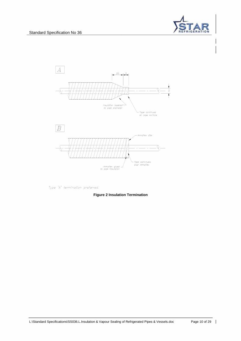
Insulation sections are to be applied using adhesive on all joints. All joints are to be close fitting and are to be staggered both circumferentially and longitudinally. Special attention shall be paid to achieving good sealed joints at the supports, refer to section 6.0 below. Vessel vapour seal and insulation shall extend to include heat breaks. Insulation shall extend 500mm past valves etc onto un-insulated pipework. Where appropriate the insulation on a vessel domed end shall be either squared off (preferred) and filled or the end shall be domed. Note, where the insulation is squared off and a fire resistant type then the filling shall be fire resistant to an equal specification although this is difficult to source and domed ends may be required. Insulated pipework penetrating insulated panels shall be formed as per Figure 1. The plastic sleeve shall be supplied by the insulation subcontractor with dimensions as shown (for different insulation thickness, consult Technical Department). Typical insulation terminations are shown in Figure 2.
6.0 Seam Sealant and Glue
The seam sealant and glue act to hold the insulation sections in place and to provide a seal between the sections. Both Coldset 183 (from Colas Flooring and Industrial) and Foster Koldfas Adhesive 82-08 (from Industrial Adhesives Ltd) are approved. Seam sealant and glue shall be applied to all edges of pre-formed insulation sections on all layers but is not required on the inner and outer surfaces of the insulation sections.
7.0 Supports 7.1 Vessel Supports
Ertalon 6SA is to be used for vessel support thermal breaks. Ertalon 6SA is a nylon based high density (1140 kg/m³) polyamide plastic. On some petrochem sites nylon based materials are not allowed. For these contracts Cestilite ASTL material would usually be acceptable. Both Ertalon and Cestilite are available from Quadrant Engineering Plastics.
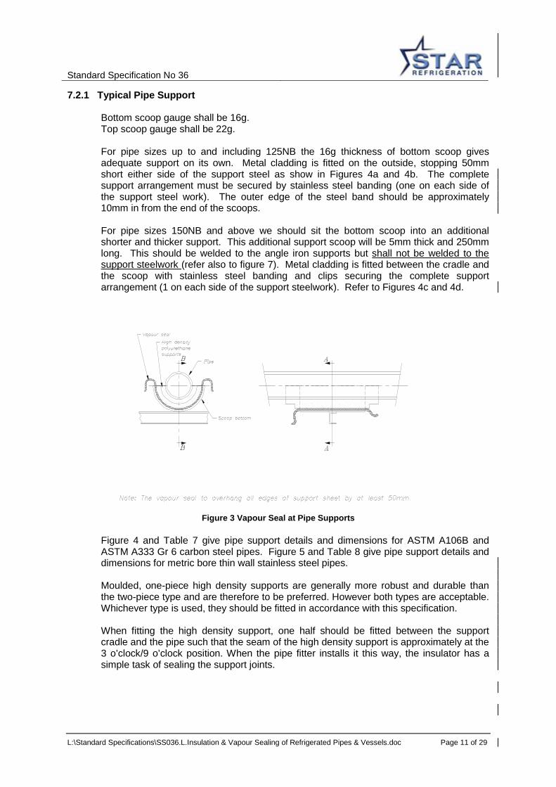
7.2 Pipe Supports A typical vapour seal is shown in Figure 3.
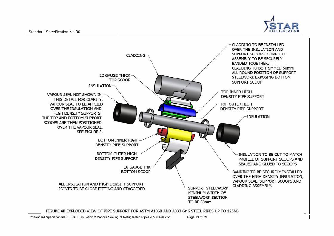
Figure 4 gives pipe support details for ASTM A106B and A333 Gr 6 pipes. Figure 5 gives pipe support details for Metric Bore Thin Wall Stainless Steel Pipes.
High density pipe supports will have longitudinal and circumferential staggered joints as shown in Figure 6.

Standard Specification No 36
L:\Standard Specifications\SS036.L.Insulation & Vapour Sealing of Refrigerated Pipes & Vessels.doc Page 8 of 29
Pipe supports shall be made from Phenolic foam or Nilflam (PIR) sections, refer to appendix 1, with the following minimum density:
• 80 kg/m3 up to and including 100NB pipe. • 120 kg/m3 for 125 NB and above.
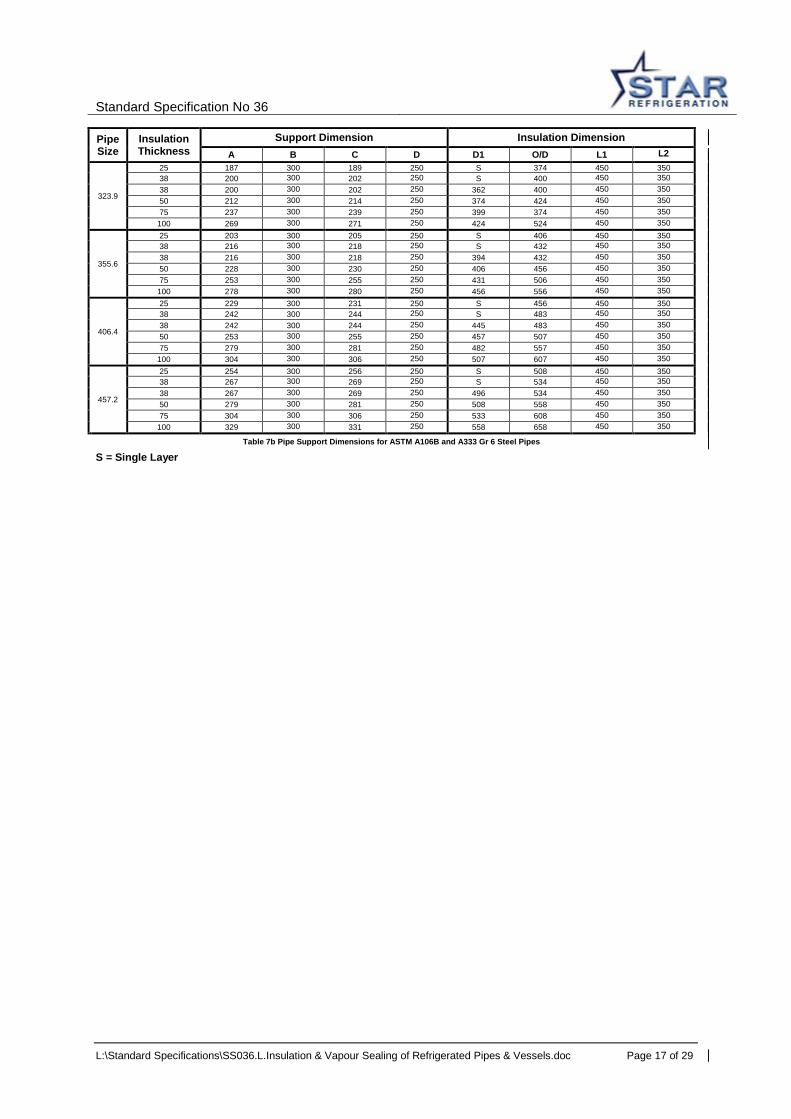
Table 7 gives the pipe support dimensions for ASTM A106B and A333 Gr 6 pipe and shows the required dimensions of the lower and upper rigid high density polyurethane supports. The upper sections are now the same length as the lower sections. The bracket steel below the pipe support scoop shall have a minimum width of 50mm. Table 8 gives the pipe support dimensions for Metric Bore Thin Wall Stainless Steel Pipes.

Standard Specification No 36
L:\Standard Specifications\SS036.L.Insulation & Vapour Sealing of Refrigerated Pipes & Vessels.doc Page 10 of 29
Figure 2 Insulation Termination
Standard Specification No 36
L:\Standard Specifications\SS036.L.Insulation & Vapour Sealing of Refrigerated Pipes & Vessels.doc Page 11 of 29
7.2.1 Typical Pipe Support
Bottom scoop gauge shall be 16g. Top scoop gauge shall be 22g. For pipe sizes up to and including 125NB the 16g thickness of bottom scoop gives adequate support on its own. Metal cladding is fitted on the outside, stopping 50mm short either side of the support steel as show in Figures 4a and 4b. The complete support arrangement must be secured by stainless steel banding (one on each side of the support steel work). The outer edge of the steel band should be approximately 10mm in from the end of the scoops. For pipe sizes 150NB and above we should sit the bottom scoop into an additional shorter and thicker support. This additional support scoop will be 5mm thick and 250mm long. This should be welded to the angle iron supports but shall not be welded to the support steelwork (refer also to figure 7). Metal cladding is fitted between the cradle and the scoop with stainless steel banding and clips securing the complete support arrangement (1 on each side of the support steelwork). Refer to Figures 4c and 4d.
Figure 3 Vapour Seal at Pipe Supports
Figure 4 and Table 7 give pipe support details and dimensions for ASTM A106B and ASTM A333 Gr 6 carbon steel pipes. Figure 5 and Table 8 give pipe support details and dimensions for metric bore thin wall stainless steel pipes. Moulded, one-piece high density supports are generally more robust and durable than the two-piece type and are therefore to be preferred. However both types are acceptable. Whichever type is used, they should be fitted in accordance with this specification. When fitting the high density support, one half should be fitted between the support cradle and the pipe such that the seam of the high density support is approximately at the 3 o’clock/9 o’clock position. When the pipe fitter installs it this way, the insulator has a simple task of sealing the support joints.

Standard Specification No 36
L:\Standard Specifications\SS036.L.Insulation & Vapour Sealing of Refrigerated Pipes & Vessels.doc Page 12 of 29
Standard Specification No 36
L:\Standard Specifications\SS036.L.Insulation & Vapour Sealing of Refrigerated Pipes & Vessels.doc Page 13 of 29

Standard Specification No 36
L:\Standard Specifications\SS036.L.Insulation & Vapour Sealing of Refrigerated Pipes & Vessels.doc Page 14 of 29

Standard Specification No 36
L:\Standard Specifications\SS036.L.Insulation & Vapour Sealing of Refrigerated Pipes & Vessels.doc Page 15 of 29

Standard Specification No 36
L:\Standard Specifications\SS036.L.Insulation & Vapour Sealing of Refrigerated Pipes & Vessels.doc Page 16 of 29
Pipe Size
Insulation Thickness
Support Dimension Insulation Dimension A B C D D1 O/D L1 L2
21.3
25 36 250 N/A N/A S 72 300 300 38 49 250 N/A N/A S 98 300 300 38 49 250 N/A N/A 60 98 300 300 50 61 250 N/A N/A 72 121 300 300 75 86 250 N/A N/A 72 172 300 300
26.7
25 38.5 250 N/A N/A S 77 300 300 38 52 250 N/A N/A S 104 300 300 38 52 250 N/A N/A 65 104 300 300 50 63.5 250 N/A N/A 77 127 300 300 75 89 250 N/A N/A 77 177 300 300
33.4
25 42 250 N/A N/A S 84 300 300 38 55 250 N/A N/A S 110 300 300 38 55 250 N/A N/A 72 110 300 300 50 67 250 N/A N/A 84 134 300 300 75 92 250 N/A N/A 84 184 300 300
42.2
25 47 250 N/A N/A S 93 300 300 38 60 250 N/A N/A S 119 300 300
38 60 250 N/A N/A 81 119 300 300 50 71 250 N/A N/A 92 142 300 300 75 97 250 N/A N/A 92 193 300 300
48.3
25 49 250 N/A N/A S 98 300 300 38 63 250 N/A N/A S 125 300 300 38 63 250 N/A N/A 87 125 300 300 50 74 250 N/A N/A 98 148 300 300 75 99 250 N/A N/A 98 198 300 300
60.3
25 55 250 N/A N/A S 110 400 300 38 69 250 N/A N/A S 137 400 300 38 69 250 N/A N/A 99 137 400 300 50 80 250 N/A N/A 110 160 400 300 75 105 250 N/A N/A 110 210 400 300 100 130 250 N/A N/A 160 260 400 300
73.0
25 62 250 N/A N/A S 123 400 300 38 75 250 N/A N/A S 149 400 300 38 75 250 N/A N/A 111 149 400 300 50 87 250 N/A N/A 123 173 400 300 75 112 250 N/A N/A 123 223 400 300 100 137 250 N/A N/A 173 273 400 300
88.9
25 70 250 N/A N/A S 139 400 300 38 83 250 N/A N/A S 165 400 300 38 75 250 N/A N/A 127 165 400 300 50 95 250 N/A N/A 139 189 400 300 75 120 250 N/A N/A 139 239 400 300 100 145 250 N/A N/A 189 289 400 300
114.3
25 82 250 N/A N/A S 164 400 300 38 96 250 N/A N/A S 191 400 300 38 96 250 N/A N/A 153 191 400 300 50 107 250 N/A N/A 164 214 400 300 75 132 250 N/A N/A 164 264 400 300 100 158
250 N/A N/A 214 314 400 300
141.3
25 96 300 N/A N/A S 192 450 350 38 109 300 N/A N/A S 218 450 350 38 109 300 N/A N/A 180 218 450 350 50 121 300 N/A N/A 192 242 450 350 75 146 300 N/A N/A 192 292 450 350 100 172 300 N/A N/A 242 342 450 350
168.3
25 109 300 111 250 S 218 450 350 38 123 300 125 250 S 245 450 350 38 123 300 125 250 207 245 450 350 50 134 300 136 250 218 268 450 350 75 159 300 161 250 218 318 450 350 100 184 300 186 250 268 368 450 350
219.1
25 135 300 137 250 S 269 450 350 38 148 300 150 250 S 296 450 350 38 148 300 150 250 258 296 450 350 50 160 300 162 250 269 319 450 350 75 185 300 187 250 269 269 450 350 100 210 300 212 250 319 419 450 350
273.0
25 162 300 164 250 S 323 450 350 38 175 300 177 250 S 349 450 350 38 175 300 177 250 311 349 450 350
50 187 300 189 250 323 373 450 350 75 212 300 214 250 323 423 450 350 100 237 300 239 250 373 473 450 350 Table 7a Pipe Support Dimensions for ASTM A106B and A333 Gr 6 Steel Pipes
Standard Specification No 36
L:\Standard Specifications\SS036.L.Insulation & Vapour Sealing of Refrigerated Pipes & Vessels.doc Page 17 of 29
Pipe Size
Insulation Thickness
Support Dimension Insulation Dimension A B C D D1 O/D L1 L2
323.9
25 187 300 189 250 S 374 450 350 38 200 300 202 250 S 400 450 350 38 200 300 202 250 362 400 450 350 50 212 300 214 250 374 424 450 350 75 237 300 239 250 399 374 450 350 100 269 300 271 250 424 524 450 350
355.6
25 203 300 205 250 S 406 450 350 38 216 300 218 250 S 432 450 350 38 216 300 218 250 394 432 450 350 50 228 300 230 250 406 456 450 350 75 253 300 255 250 431 506 450 350 100 278 300 280 250 456 556 450 350
406.4
25 229 300 231 250 S 456 450 350 38 242 300 244 250 S 483 450 350 38 242 300 244 250 445 483 450 350 50 253 300 255 250 457 507 450 350 75 279 300 281 250 482 557 450 350 100 304 300 306 250 507 607 450 350
457.2
25 254 300 256 250 S 508 450 350 38 267 300 269 250 S 534 450 350 38 267 300 269 250 496 534 450 350 50 279 300 281 250 508 558 450 350 75 304 300 306 250 533 608 450 350 100 329 300 331 250 558 658 450 350
Table 7b Pipe Support Dimensions for ASTM A106B and A333 Gr 6 Steel Pipes
S = Single Layer

Standard Specification No 36
L:\Standard Specifications\SS036.L.Insulation & Vapour Sealing of Refrigerated Pipes & Vessels.doc Page 18 of 29
Figure 5 Pipe Support Details for Metric Bore Thin Wall Stainless Steel (TWSS) Pipes
METRIC BORE TWSS
O/D
INSULATION THICKNESS
SUPPORT DIMENSION INSULATION DIMENSION A B I/D O/D L1
18 25 34 250 18 68 300
23 25 36.5 250 23 73 300 28 25 39 250 28 78 300 35 25 42.5 250 35 85 300 43 25 46.5 250 43 93 300 54 25 52 250 54 104 300
70 25 59.5 250 69 119 300
84 25 67 250 84 134 300
104 25 77 250 104 154 300
129 25 89.5 300 129 179 350
154 25 102 300 154 204 350
206 25 128 300 206 256 350
254 25 152 300 254 304 350
Table 8 Pipe Support Dimensions for Metric Bore Thin Wall Stainless Steel (TWSS) Pipes
For thin wall stainless steel pipe 154mm OD and above, the extra cradle should be added as per figure 4 (where dimension D is 250mm as per Table 7).
Standard Specification No 36
L:\Standard Specifications\SS036.L.Insulation & Vapour Sealing of Refrigerated Pipes & Vessels.doc Page 19 of 29
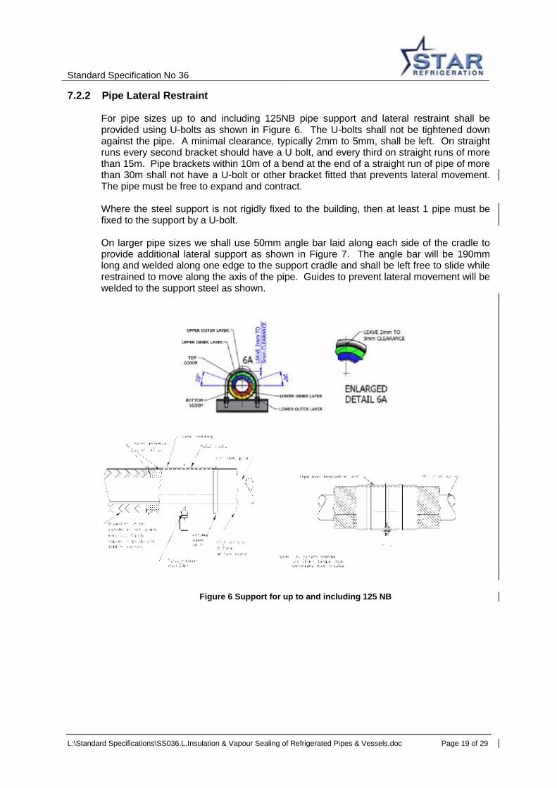
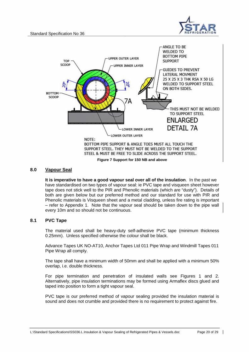
7.2.2 Pipe Lateral Restraint For pipe sizes up to and including 125NB pipe support and lateral restraint shall be provided using U-bolts as shown in Figure 6. The U-bolts shall not be tightened down against the pipe. A minimal clearance, typically 2mm to 5mm, shall be left. On straight runs every second bracket should have a U bolt, and every third on straight runs of more than 15m. Pipe brackets within 10m of a bend at the end of a straight run of pipe of more than 30m shall not have a U-bolt or other bracket fitted that prevents lateral movement. The pipe must be free to expand and contract. Where the steel support is not rigidly fixed to the building, then at least 1 pipe must be fixed to the support by a U-bolt. On larger pipe sizes we shall use 50mm angle bar laid along each side of the cradle to provide additional lateral support as shown in Figure 7. The angle bar will be 190mm long and welded along one edge to the support cradle and shall be left free to slide while restrained to move along the axis of the pipe. Guides to prevent lateral movement will be welded to the support steel as shown.
Figure 6 Support for up to and including 125 NB
Standard Specification No 36
L:\Standard Specifications\SS036.L.Insulation & Vapour Sealing of Refrigerated Pipes & Vessels.doc Page 20 of 29
Figure 7 Support for 150 NB and above
8.0 Vapour Seal It is imperative to have a good vapour seal over all of the insulation. In the past we
have standardised on two types of vapour seal: ie PVC tape and visqueen sheet however tape does not stick well to the PIR and Phenolic materials (which are “dusty”). Details of both are given below but our preferred method and our standard for use with PIR and Phenolic materials is Visqueen sheet and a metal cladding, unless fire rating is important – refer to Appendix 1. Note that the vapour seal should be taken down to the pipe wall every 10m and so should not be continuous.
8.1 PVC Tape
The material used shall be heavy-duty self-adhesive PVC tape (minimum thickness 0.25mm). Unless specified otherwise the colour shall be black. Advance Tapes UK NO-AT10, Anchor Tapes Ltd 011 Pipe Wrap and Windmill Tapes 011 Pipe Wrap all comply. The tape shall have a minimum width of 50mm and shall be applied with a minimum 50% overlap, i.e. double thickness. For pipe termination and penetration of insulated walls see Figures 1 and 2. Alternatively, pipe insulation terminations may be formed using Armaflex discs glued and taped into position to form a tight vapour seal. PVC tape is our preferred method of vapour sealing provided the insulation material is sound and does not crumble and provided there is no requirement to protect against fire.

Standard Specification No 36
L:\Standard Specifications\SS036.L.Insulation & Vapour Sealing of Refrigerated Pipes & Vessels.doc Page 21 of 29
Pipe insulation vapour seal shall be terminated in such a way that it is possible to remove valve insulation boxes etc without breaking the vapour barrier on the main length of pipework.
8.2 Visqueen Sheet Where the insulation is being finally protected by a metal cladding, i.e. aluminium, alu-zinc or stainless steel, our standard vapour seal is heavy gauge visqueen as shown in Figure 3. Visqueen is a PVC sheet and should be at least 0.25mm thick. This is Visqueen damp proof course “PIFA standard”. The visqueen shall be sealed at all joints with PVC tape, as above. It is important that the visqueen sheet is wiped clean of dust before applying the PVC tape to the joints.
8.3 VentureClad
Our Type C insulation calls for VentureClad 1577 CW aluminium foil and PVC layered vapour seal which will be protected by metal cladding.
The VentureClad shall be sealed at all joints with VentureClad 1577 CW tape.
9.0 Metal Cladding Our standard metal cladding for vessels is 0.7mm alu-zinc.
Our standard metal cladding for pipework is 0.4mm or 0.5mm (preferred by the insulation contractor) alu zinc.
Where aluminium is specified by the customer we will use 0.7mm stucco on vessels and 0.7mm stucco on pipework. Metal cladding shall be secured with bright annealed stainless steel banding 0.56mm x 12mm and clips.
Metal cladding on straight pipework and equipment shall overlap by at least 50mm. Joints in boxes, bends etc shall be interlocked. Metal cladding shall be arranged to shed water with particular care on the top of vertical vessels. Joints on outdoor metal cladding shall be sealed with silicone mastic. 3mm thick self adhesive Armaflex tape shall be used at penetrations of valve spindles, instruments etc through the metal cladding and boxes to prevent the cladding damaging the vapour barrier, valve spindles and instruments. Pop rivets shall not be used to fix cladding unless as below. Pop rivets can puncture the visqueen vapour seal and allow penetration of moisture into the insulation material. Pop rivets used to make pre-formed sections (e.g. bends) shall be hammered flat on the inside then the flattened part will be covered with 3mm thick self adhesive Armaflex tape. Sacrificial layers of insulation shall not be used as they become water logged so increasing the likelihood of water penetration of the vapour barrier.
All valve boxes and flange boxes will be fixed with toggle clips for ease of removal and maintenance.

Standard Specification No 36
L:\Standard Specifications\SS036.L.Insulation & Vapour Sealing of Refrigerated Pipes & Vessels.doc Page 22 of 29
10.0 Valve Station Insulation and Drip Trays
We will use drip trays on hot gas defrost valve stations where it is acceptable to the customer and/or consultant. Total drip tray cost with stainless steel trays is typically equal to insulating the valve station. Insulation will continue up to approximately 100mm from valves and flanges including on wet return bypass valves with clearance only to allow valve access and bolt removal from flanges. Valve station drip trays need to be piped to drain. The drain can be into the cooler drain and on glycol and CO2 systems this can be inside a chill store (not a cold store) as long as the drip tray drain has a trap greater than 150mm deep in the roof void and connects to the cooler drain after the trap at the cooler outlet. Draining the valve station drip tray to the cooler drain is not allowed if it would mean a refrigerant leak would allow a volatile refrigerant to flow down the drain into an occupied space.
All other valve stations, except 4 way ball valves and package unit expansion valve stations, will be insulated.
10.1 Valve Insulation
• Expanded foam insulation is not acceptable on ‘fire rated’ contracts. • Un-insulated valves pipework and flanges will be painted with black bitumastic paint
(single coat only, minimum dry film thickness 80 microns). • Aluminium valve boxes will be formed with spring clasps to hold the two parts
together. • Inside of valve boxes will be lined with foil or polythene. • Valves will be wrapped with foil or polythene. • Expanding foam will be injected inside the valve box. • Seams and foam injection points on the valve boxes will be sealed with clear silicone
sealant.
It should be noted that this system is far from ideal as it is difficult to remove the valve box without damaging it (although lining the box helps substantially). Removing expanded foam without breaking it is almost impossible and this is the main reason we prefer drip trays.
10.2 Valve Insulation – Alternative using Armaflex
Armaflex is a good alternative, but only for higher temperature (chill) applications. It is cost effective and easier to repair. However, Armaflex is difficult to apply properly and does not give as good a finished product. Armaflex should ideally only be used at the valve station and never at pipe supports. The pipe itself should be insulated with rigid section.
• Valves shall be painted with black bitumastic paint (single coat only, minimum dry
film thickness 80 microns). • Spaces and narrow points will be filled with small pieces of Armaflex out to the
outside diameter of the associated pipe insulation. • An outer layer of Armaflex will pass over the valve and at least 50mm of pipe
insulation on either side. The seam will be glued and the surface will be painted with black rubber paint.

Standard Specification No 36
L:\Standard Specifications\SS036.L.Insulation & Vapour Sealing of Refrigerated Pipes & Vessels.doc Page 23 of 29
It is very difficult to obtain a good vapour seal around solenoid coils etc., so this method is not allowed for temperatures below -10ºC where ice would tend to burst away the insulation.
10.3 Stop Valves
Stop valves should be insulated as the pipework. Typically this will mean with rigid section cut to shape, expanding foams (not for fire rated insulation) to fill spaces and tape (not for fire rated insulation) as the vapour seal. Tape shall be used to vapour seal valves, even if Visqueen type sheet is used on the pipework. With Type C insulation (refer to Appendix 1) we will fill the spaces with shaped insulation section and vapour seal with VentureClad 1577 CW tape.
10.4 Caution Regarding Fibrous Insulation
Fibrous insulation (e.g. Rockwool) is easy to remove and replace but must not be used (even with a good vapour seal) as insulation on low temperature equipment (where the pipes, valves etc are colder than surrounding air) as it will soak up moisture and be totally ineffective.
10.5 Strainers and Pumps
Strainers should be treated as valves described above. It is preferable to leave larger strainers and pumps on secondary refrigerant circuits and primary refrigerant pumps un- insulated but mounted over bunded areas or drip trays.
11.0 Insulation of Miscellaneous Equipment 11.1 Water Pipework Frost Protection
Emergency shower pipework and evaporative condenser water feed pipe, pump and pump inlet pipework will be trace heated with self limiting heater tape and insulated with heavy density, foil backed, rigid section mineral wool – Rockwool Process Pipe Insulation minimum density 120kg/m3and clad with aluminium. The cladding is sufficient weather protection for the insulation and a vapour seal is not important. Aluminium tape shall be applied below the cladding to make a tidy finish without insulation material showing at cladding joins.
11.2 Drain Pipework
Drain lines in areas below 0ºC will be insulated with a single layer of Armaflex applied in either sections or sheet form. The adhesive used shall be Armaflex 520 or approved equivalent. Metal clad Nilflam is an acceptable alternative to Armaflex.
11.3 Copper Pipework and Fittings
Copper pipework and fittings will be insulated with Armaflex sections and sheet. The adhesive used shall be Armaflex 520 or approved equivalent.

Standard Specification No 36
L:\Standard Specifications\SS036.L.Insulation & Vapour Sealing of Refrigerated Pipes & Vessels.doc Page 24 of 29
Rev Date Changes Originator 01 01-02-88 02 01-01-95 ADM 03 01-09-95 DJH / ADM 04 01-06-01 DJH 05 01-10-01 DJH F 14-02-03 1. Clarify materials which can be used where there are
special fire rating requirements and give guidance on fire ratings of insulation.
2. Specify an alternative method of providing pipe support on larger sizes of insulated pipes.
3. Take a slightly more conservative approach to the sizing for pipe and vessel insulation below -30ºC.
4. Give a clear specification that we can refer to and sub-contractors can work to.
5. Add valve station insulation. 6. Add miscellaneous equipment insulation.
DJH / AMG
G 27/05/05 Tables 1, 2, 3 and 4 call for the use of a single layer of 38mm thick insulation material where appropriate. Tables 3, 4 and 6 give insulation thicknesses for Nilflam and Phenolic material. Figure 4 and Table 7 show support details for ASTM steel pipe. Figure 5 and Table 8 show support details for TWSS pipe. Subsequent figures renumbered.
DJH
DJH
DJH DJH
H 13/04/06 Tables 5 and 6 headings corrected to read “Vessel Temperature” Table 6 thicknesses changed from 38 (19 + 19) to 50 (25 + 25) and from 25 to 40
DJH
I 19/07/07 Tables 1 to 6 now include temperatures down to -50ºC. Tables 1 to 4 and Table 7 now include pipe sizes up to 457.2mm outside diameter. Notes added to Table 5 and 6. Cladding thicknesses clarified. Smooth alu-zinc cladding is now our standard.
DJH
J 26/08/09 Preferred sectional insulating material and high density supports changed to Nilflam. Figure 6 references changed to Nilflam
GTS
K 01/11/11 Figures 4, 7 and Table 7and 8 updated to clarify pipe support arrangements.
RWT
L 18/05/12 Revised to clarify pipe support details and to revise insulation requirements for external pipework. Painting requirements have also been revised. Fig. 1 updated to include plastic sleeve Fig. 4 Pipe Support Details replaced with Fig. 4a, 4b, 4c, and 4d Tables 7a, 7b and 8 updated Fig. 6 and 7 updated
RWT
Standard Specification No 36
L:\Standard Specifications\SS036.L.Insulation & Vapour Sealing of Refrigerated Pipes & Vessels.doc Page 25 of 29
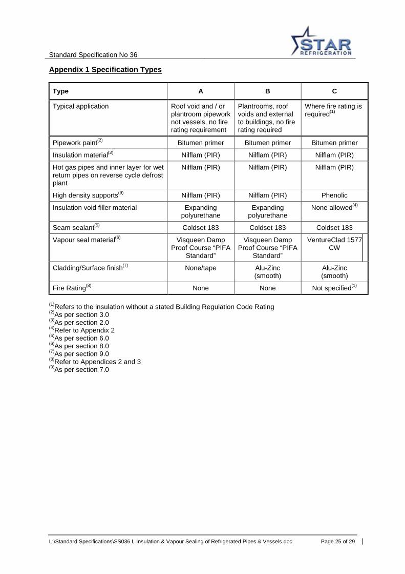
Appendix 1 Specification Types
Type A B C
Typical application Roof void and / or plantroom pipework not vessels, no fire rating requirement
Plantrooms, roof voids and external to buildings, no fire rating required
Where fire rating is required(1)
Pipework paint(2) Bitumen primer Bitumen primer Bitumen primer
Insulation material(3) Nilflam (PIR) Nilflam (PIR) Nilflam (PIR)
Hot gas pipes and inner layer for wet return pipes on reverse cycle defrost plant
Nilflam (PIR) Nilflam (PIR) Nilflam (PIR)
High density supports(9) Nilflam (PIR) Nilflam (PIR) Phenolic
Insulation void filler material Expanding polyurethane
Expanding polyurethane
None allowed(4)
Seam sealant(5) Coldset 183 Coldset 183 Coldset 183
Vapour seal material(6) Visqueen Damp Proof Course “PIFA
Standard”
Visqueen Damp Proof Course “PIFA
Standard”
VentureClad 1577 CW
Cladding/Surface finish(7) None/tape Alu-Zinc (smooth)
Alu-Zinc (smooth)
Fire Rating(8) None None Not specified(1) (1)Refers to the insulation without a stated Building Regulation Code Rating (2)As per section 3.0 (3)As per section 2.0 (4)Refer to Appendix 2 (5)As per section 6.0 (6)As per section 8.0 (7)As per section 9.0 (8)Refer to Appendices 2 and 3 (9)As per section 7.0

Standard Specification No 36
L:\Standard Specifications\SS036.L.Insulation & Vapour Sealing of Refrigerated Pipes & Vessels.doc Page 26 of 29
Appendix 2 Recommended Fire Resistant Insulation Star Refrigeration recommend the following insulation specification where a fire rating is required. The overall insulation package including paint, insulating material, glue, vapour seal and metal cladding is not claimed to be Class 0 or Class 1 to the Building Regulations due to the effect of the other materials on the insulation itself. However it has been carefully considered and is Star Refrigeration’s current recommendation to customers and their insurers. Star Refrigeration recommend that customers forward a copy to their insurer for approval.
Insulation Material PIR (Nilflam) density >33kg/m3 Flame spread <25 under ASTM E84 Building Regulations Class 1 to BS 476: Part 7 (for the insulation material on its own) Cladding/Surface Finish Alu-zinc with stainless steel banding as per section 9.0 of this specification. Vapour Seal Material VentrureClad 1577 CW UL Listed. Exceed requirements of UL 723 (25/50 Flame/Smoke Rating) BS 476, Part 6 & 7, Class 1; EN ISO 1716 3, 5 MJ/m2 (calculated); Building Regulation – Class 0
Insulation Seam Sealant Coldset 183 (water based) COSHH data sheet classification: Non Flammable High Density Pipe Supports (Kooltherm) Phenolic foam (80kg/m3) with a factory applied reinforced Class 0 aluminium foil barrier BS 476 Part 7; surface spread of flame rating Class 1. BS 476 Part 6 fire propagation main index 1< 12, sub index I < 6. Building Regulations, Approved Document B, Class 0. Aluminium foil vapour barrier jacket fire rating Class 0 High Density Pipe Supports Alternative (Nilflam) PIR (Nilflam) (80kg/m3) a flame spread < 25 under ASTM E84 Building Regulation Class 1 to BS 476: Part 7
Insulation Voids None allowed – spaces to be filled with shaped sections of the vessel or pipework pre-formed insulating material. Pipework Paint (Bitumen) Bitumen paint. Note: this paint is solvent based. Consult Star Refrigeration for an alternative if required. This paint is recommended for its proven long term corrosion protection which is not offered by other site applied finishes.

Standard Specification No 36
L:\Standard Specifications\SS036.L.Insulation & Vapour Sealing of Refrigerated Pipes & Vessels.doc Page 27 of 29
Appendix 3 Guidance on Fire Ratings The terms Class 1 and Class 0 are often used to specify the fire resistance of insulation. Class 0 is the most resistant. The classification comes from the Building Regulations:
• Appendix A (paragraph 12) of Approved Document B, Fire Safety to the Building Regulations (England and Wales) 1991
• Appendix to Part D (paragraph 6a), Structural Fire Precautions of the technical standards for compliance with the Building Standards (Scotland) Regulations 1990
• Section 2 (paragraph 2.4) of Technical Booklet E, Fire Safety, to the Building Regulations (Northern Ireland) 1994
However, this is a material / product performance classification for wall and ceiling linings, it does not apply to insulated refrigeration pipes, although they can be assessed in the same way. Class 0 is not a classification identified by any British or European standard. It should not be assumed that a material / product with a Class 0 classification is non-combustible, Class 0 doesn’t even imply non-combustibility or limited combustibility. Class 0 could be assessed by confirming that the complete finished product (in our case vapour sealed and possibly clad insulation right down to the metal of the pipe) complies with BS 476 Part 7: 1997 for surface spread of flame and BS 476 Part 6: 1989 for fire propagation. The results of these tests have to meet pre-set levels before Class 0 can be claimed. In simple terms the product has to have limited ability to spread flames or burn of its own accord. It is the responsibility of the person making the claim to explain how these are determined or checked. Star Refrigeration or our approved insulation sub-contractors are not currently in a position to make that claim for a product we are happy to endorse as a good quality insulation and corrosion prevention product for industrial refrigeration pipework and vessels. If this is a customer requirement and they do not accept our Type C proposal please refer to the Technical Department who are further investigating the possibility of gaining type approval for our Type C insulation. BS 476 Part 7 classifies products as Class 1, 2, 3 and 4. These do not relate directly to the Building Regulation classification numbers. In fact Class 1 of BS 476 Part 7 is the highest classification available and is commonly used in claiming a product complies with Building Regulation Class 0. BS 476 Part 6 test results are expressed in terms of fire propagation index, I and three sub-indices i1, i2, and i3. The higher the fire propagation index the greater is the influence of the product in accelerating the growth of a fire. It is not possible to claim the finished pipe insulation is Class 0 unless every element from pipework anti-corrosion paint through the insulation and glue to the vapour seal and cladding are fully assessed as one finished product, possibly by type testing. Even then installation would most likely have to be under ISO 9000 with audit testing of randomly selected product. Refer to Appendix 1 Type C and Appendix 2 for our recommended insulation where the customer wants a good fire rating. This specification should be passed to our customer with a recommendation that they propose it to their insurer for approval, without any claim that it will meet a specific Building Regulation Classification.
Standard Specification No 36
L:\Standard Specifications\SS036.L.Insulation & Vapour Sealing of Refrigerated Pipes & Vessels.doc Page 28 of 29
Nilflam (PIR) has been chosen as our recommended insulation over Phenolic, which can have better fire ratings, as Nilflam has better mechanical properties and so is more robust as well as being easier to work with and having better low temperature characteristics. A disadvantage of Nilflam over some Phenolic products is that it doesn’t have such a good rating with regard to the smoke given off so Phenolic could be preferred in some instances, particularly public buildings such as schools and hospitals. Please refer requirements for Phenolic with a fire rating to the Technical Department. When subjected to fire the outer surface of Nilflam forms a strong carbonaceous layer that retards further flame spread and penetration. It does not melt or produce flaming droplets when exposed to fire.
The alu-zinc cladding has been chosen as an effective mechanical protection without the fire risks of aluminium or the considerable cost of stainless steel. The cladding is very important to the Building Regulation Classification of the finished product. It is possible for Nilflam to be rated as Building Regulation Class 0 when clad but not without the cladding.

Standard Specification No. 36
L:\Standard Specifications\SS036.L.Insulation & Vapour Sealing of Refrigerated Pipes & Vessels.doc Page 29 of 29
Appendix 4 Suggested Paragraphs for Quotations We should consider adding the following to our quotations: Insulation All low temperature pipework will be insulated and vapour sealed in accordance with a Star Standard Specification. Insulation of cold pipes in voids and vessels will be from pre-formed polystyrene sections. High density sections in rigid clamped cradles will be used at support points. Sales staff to note here the type and scope of cladding. Smooth alu-zinc is now our standard. Insulation thickness is chosen to prevent the surface of the vapour seal falling to more than 2ºC below the temperature of the surrounding air. It is essential that the ventilation system installed is capable of producing adequate air movement over the pipes. We would be pleased to make available an alternative specification with our suggested fire resistant insulation, in which case we recommend that the specification is passed to your insurance company for approval. The standard list of exclusions should include: “Ventilation or heating of roof voids or similar spaces to prevent condensation on the surface of insulated pipes under conditions high of humidity”