ssp362 audi q7 - running gear - seu portal volkswagen. · vehicle (suv) segment. the audi q7...
TRANSCRIPT
36
2
All rights reserved. Technical specifications subject to change without notice.
CopyrightAUDI AGI/[email protected] +49-841/89-36367
AUDI AGD-85045 IngolstadtTechnical status: 11/05
Printed in GermanyA05.5S00.15.20
Audi Q7 - Running Gear
Self-Study Programme 362
Vorsprung durch Technik www.audi.de Service Training

With the Q7 Audi offers a vehicle that marks a superlative new development in the sport utility vehicle (SUV) segment. The Audi Q7 ingeniously combines sportiness and versatility, sophisticated technology and the luxury of a premium-class vehi-cle. On the road it excels with the driving perform-ance and dynamism of a sports car; off-road it redefines the benchmark in its category. The chassis of the Audi Q7 also excels with its all-round quali-ties.
362_076
Steel-spring suspension and twin-tube shock absorbers are designed for sporty driving and supe-rior comfort, even off-road. Also available on request: adaptive air suspension. The combination of air suspension and an electronically controlled damping system represents the perfect synthesis of decidedly sporty handling and supreme ride com-fort.

NoteReferenceThis Self-Study Programme teaches the design and function of new vehicle models, new automotive compo-nents or new technologies.
The self-study programme is not a workshop manual!All values given are intended as a guideline only, and refer to the software version valid at the time of publication of the SSP.
Please refer to the relevant service literature for current inspection, adjustment and repair instructions.
Contents
Front axle
Overview . . . . . . . . . . . . . . . . . . . . . . . . . . . . . . . . . . . . . . . . . . . . . . . . . . . . . . . . . . . . . 5
Rear suspension
Overview . . . . . . . . . . . . . . . . . . . . . . . . . . . . . . . . . . . . . . . . . . . . . . . . . . . . . . . . . . . . . 6
Brake system
Overview . . . . . . . . . . . . . . . . . . . . . . . . . . . . . . . . . . . . . . . . . . . . . . . . . . . . . . . . . . . . . 7
Foot-operated handbrake . . . . . . . . . . . . . . . . . . . . . . . . . . . . . . . . . . . . . . . . . . . . . . 8
The active brake servo . . . . . . . . . . . . . . . . . . . . . . . . . . . . . . . . . . . . . . . . . . . . . . . . 12
ESP
Steering / wheels and tyres
Overview . . . . . . . . . . . . . . . . . . . . . . . . . . . . . . . . . . . . . . . . . . . . . . . . . . . . . . . . . . . 17
Functions in overview / New functions. . . . . . . . . . . . . . . . . . . . . . . . . . . . . . . . . . 18
System components . . . . . . . . . . . . . . . . . . . . . . . . . . . . . . . . . . . . . . . . . . . . . . . . . . 24
Service work . . . . . . . . . . . . . . . . . . . . . . . . . . . . . . . . . . . . . . . . . . . . . . . . . . . . . . . . . 26
Overview . . . . . . . . . . . . . . . . . . . . . . . . . . . . . . . . . . . . . . . . . . . . . . . . . . . . . . . . . . . . . 4
Introduction
Overview . . . . . . . . . . . . . . . . . . . . . . . . . . . . . . . . . . . . . . . . . . . . . . . . . . . . . . . . . . . 27
Wheels overview / tyre pressure check system . . . . . . . . . . . . . . . . . . . . . . . . . . . 28
Overview . . . . . . . . . . . . . . . . . . . . . . . . . . . . . . . . . . . . . . . . . . . . . . . . . . . . . . . . . . . 29
System components . . . . . . . . . . . . . . . . . . . . . . . . . . . . . . . . . . . . . . . . . . . . . . . . . . 32
Vehicle ride heights / modes . . . . . . . . . . . . . . . . . . . . . . . . . . . . . . . . . . . . . . . . . . . 38
Control response . . . . . . . . . . . . . . . . . . . . . . . . . . . . . . . . . . . . . . . . . . . . . . . . . . . . . 41
Operation and displays. . . . . . . . . . . . . . . . . . . . . . . . . . . . . . . . . . . . . . . . . . . . . . . . 42
Service work . . . . . . . . . . . . . . . . . . . . . . . . . . . . . . . . . . . . . . . . . . . . . . . . . . . . . . . . . 47
adaptive air suspension (aas)

4
The Audi Q7 is offered with a conventional steel-spring suspension; air spring suspension (aas) is optional. aas is standard equipment for the V10 TDI.
Introduction
Double wishbone rear axle with split upper wishbones
ESP MK25E1 with active brake servo
Double wishbone front axle
Ventilated 17" and 18" disc brakes front and rear
Hydraulic rack and pinion steering with Servotronic function as standard
18" wheels as standard equipment; 18"-20" wheels are optional
Available on request: adaptive air suspension
Available on request: tyre pressure moni-toring system
Tire mobility system (TMS) as standard equipment, optional folding wheel or 18" spare wheel
Foot-operated handbrake
Manually adjustable and electri-cally lockable steering column; electrical adjustment is optional
362_001
Overview

5
Front axle
Spring damper
Upper wishbone *
Swivel bearing *
Wheel bearing *
Lower wishbone– Made of aluminium
All parts marked * are common parts used in the VW Touareg
Wishbone mount– Installation position: rotated through 90° *
Anti-roll bar
Subframe *
362_072
Overview

6
Rear suspension
Wheel bearing housing– Adapted due to larger
track width (+14 mm)
Spring damper– Adapted to Q7
Lower wishbone *
Drive shafts– Modified due to larger
track width
Track rod– Lightweight construction
(tailored rolled blank)
Cross-member– Modified geometry due to third row of seats– Cast aluminium
Mounting bracket *
Anti-roll bar link and fastening clampsin aluminium
Upper wishbone, split *
362_071
Subframe– Bearing has been acoustically
optimised– SGR is a common part
Wheel bearing and wheel flange *
All parts marked * are common parts used in the VW Touareg
Overview

7
Overview
Brake system
362_036
Front axle Rear suspension
Engine V8 petrol engine, V6 FSI + TDI
V8 petrol engine V6 FSI + TDI
Minimum wheel size 18" 18" 18"
Brake type Brembo aluminiumfixed caliper
Brembo aluminiumfixed caliper
Brembo aluminiumfixed caliper
Number of brake pistons 6 4 4
Brake piston diameter (mm) 30/34/38 28/32 28/30
Brake disc diameter (mm) 350 358 330
Rear brakes
Ventilated brake discs are used. Brake lining wear is also monitored at the rear axle. A servo drum brake is employed as the handbrake.
362_037
Front wheel brakes
Ventilated brake discs are employed. Brake lining wear is monitored. The aluminium brake calipers use a monoblock construction.
8
Brake system
Foot-operated handbrake
Overview
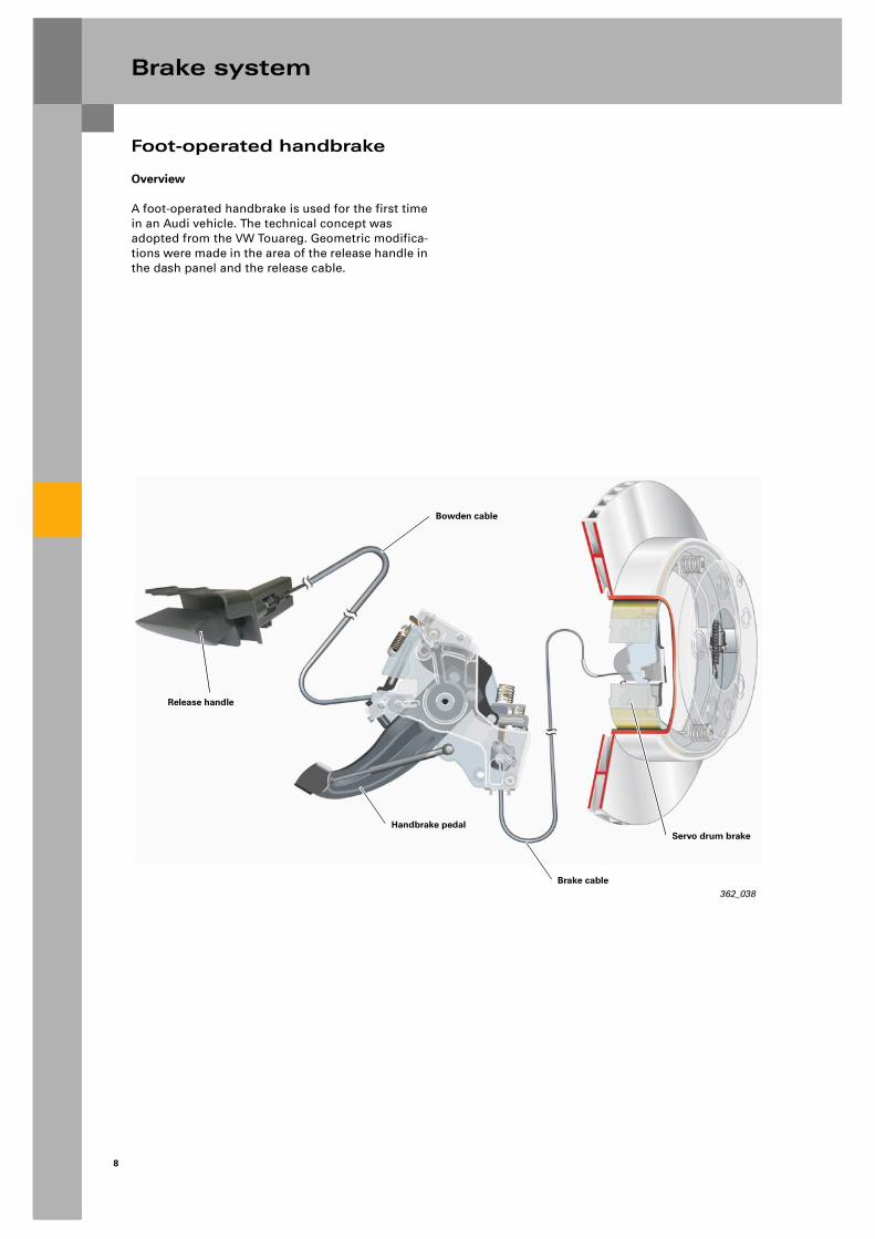
A foot-operated handbrake is used for the first time in an Audi vehicle. The technical concept was adopted from the VW Touareg. Geometric modifica-tions were made in the area of the release handle in the dash panel and the release cable.
362_038
Bowden cable
Release handle
Handbrake pedal
Brake cable
Servo drum brake

9
Foot-operated handbrake
Operating the brake
The brake cable is actuated by pressing the pedal. In the pressed position, the pedal is located in place by a locking pawl, which engages in the tooth seg-ment attached to the pedal.
362_039
Spring
Brake cable
Pedal mount
Locking pawl bearing
Locking pawl
Tooth segment
Pedal mount
Handbrake pedal
The locking pawl is mounted rotatably in the pedal mount. A spring presses the locking pawl against the tooth segment. The brake cable remains actu-ated, and the vehicle is braked.
Releasing the applied brake
When the release handle is operated, the locking pawl is lifted by the release lever against the spring force. The locking pawl is lifted out of the tooth seg-ment, and the pedal is unlocked.
The pedal slowly returns to its starting position against the damping force of the damper element. The brake cable is moved in the opposite direction and releases the handbrake.
362_040
Locking pawl
Release lever
Release cable
Handbrake pedal
Damper element Brake cable
Tooth segment
Spring

10
Brake system
Foot-operated handbrake
Automatic adjustment
Stretching of the bowden cable and settling of the bearings results in a progressive increase in back-lash in the actuator mechanism. The handbrake requires adjustment to ensure proper functioning. These adjustments are made automatically in the Q7. The adjustment mechanism is attached to the handbrake pedal. The adjustment mechanism is located between the pedal and the bowden cable.
Configuration with actuated handbrake:
The connection between the handbrake pedal and the bowden cable is made by means of a rack. The rack is rigidly attached to the cable pull on one side. The rack is located in a control arm. This rack con-trol arm is attached rotatably to the tooth segment. The release spring presses the control arm against the rack and locates it in position on the handbrake pedal. This makes a rigid connection between the pedal and the brake cable.
362_041
Release spring
Rack control arm
Rack
Brake cable

11
Foot-operated handbrake
Mode of operation of the adjustment mechanism:
When the release lever is operated, the handbrake pedal returns to its starting position. At the same time, the rack control arm comes into abutment with the stop. The rack control arm is then pushed upwards against the spring force of the release spring, releasing the rack.
The adjuster spring pulls the rack upwards until the backlash is compensated. When the handbrake pedal is operated anew, the rack control arm is again pressed against the rack by the release spring and locates the rack in position.
362_042
Adjuster spring
Rack
Release spring
Rack control arm
Stop
Servo drum brake
When the brake cable is pulled, both brake jaws are pressed simultaneously against the brake drum by the spreader lock.
362_043
Brake drum
Adjustment screwBrake lever
Brake cable
Spreader lock
Brake jaws
As before, basic adjustment of the handbrake is made using an adjustment screw.

12
Brake system
The active brake servo
The task of the active brake servo is to build up brake pressure without operation of the brake pedal by the driver. This is a requirement for specific ESP control operations. Rapid pressure build-up is essential particularly for roll-over stabilisation and for ESP intervention if the vehicle is oversteering.
For this purpose, pressure is built up by activating the active brake servo on the suction side of the ESP pump. The delivery rate of the ESP pump increases, allowing a more rapid pressure build-up.
362_070
Active brake servo
ESP pump
Electric motor
Rapid brake pres-sure build-up
Pressure build-up by active brake servo
Wheel brake
13
The active brake servo
362_045
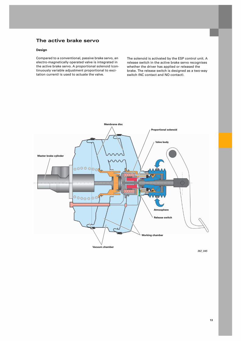
Master brake cylinder
Atmosphere
Proportional solenoid
Membrane disc
Valve body
Release switch
Working chamber
Vacuum chamber
Design
Compared to a conventional, passive brake servo, an electro-magnetically operated valve is integrated in the active brake servo. A proportional solenoid (con-tinuously variable adjustment proportional to exci-tation current) is used to actuate the valve.
The solenoid is activated by the ESP control unit. A release switch in the active brake servo recognises whether the driver has applied or released the brake. The release switch is designed as a two-way switch (NC contact and NO contact).

14
Brake system
The active brake servo
362_046
Release switch
If the driver applies the brake pedal, the actuating rod is moved. This release switch moves away from the active brake servo's housing. Electrical circuit 1 is opened, electrical circuit 2 is closed.
362_047
Actuating rod
Function of the release switch
In the rest position or when the electronic brake servo is actuated electrically, the release switch con-tacts the housing of the active brake servo and closes electrical circuit 1.
15
The active brake servo
362_048
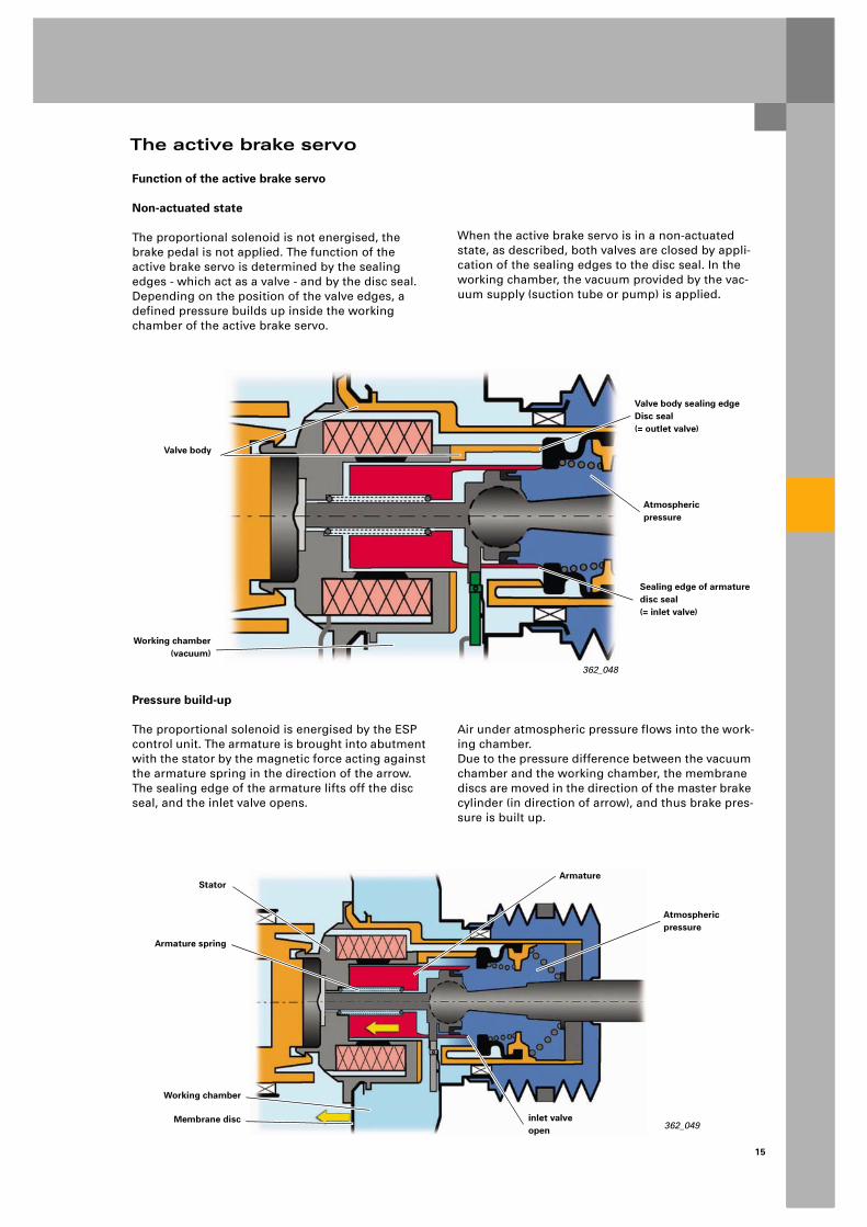
Valve body
Valve body sealing edgeDisc seal (= outlet valve)
Atmosphericpressure
Working chamber(vacuum)
Sealing edge of armaturedisc seal(= inlet valve)
Function of the active brake servo
Non-actuated state
The proportional solenoid is not energised, the brake pedal is not applied. The function of the active brake servo is determined by the sealing edges - which act as a valve - and by the disc seal. Depending on the position of the valve edges, a defined pressure builds up inside the working chamber of the active brake servo.
When the active brake servo is in a non-actuated state, as described, both valves are closed by appli-cation of the sealing edges to the disc seal. In the working chamber, the vacuum provided by the vac-uum supply (suction tube or pump) is applied.
Pressure build-up
The proportional solenoid is energised by the ESP control unit. The armature is brought into abutment with the stator by the magnetic force acting against the armature spring in the direction of the arrow. The sealing edge of the armature lifts off the disc seal, and the inlet valve opens.
Air under atmospheric pressure flows into the work-ing chamber. Due to the pressure difference between the vacuum chamber and the working chamber, the membrane discs are moved in the direction of the master brake cylinder (in direction of arrow), and thus brake pres-sure is built up.
Stator
Working chamber
inlet valveopen
Armature spring
Armature
Atmosphericpressure
Membrane disc362_049
16
Brake system
The active brake servo
Function of the active brake servo
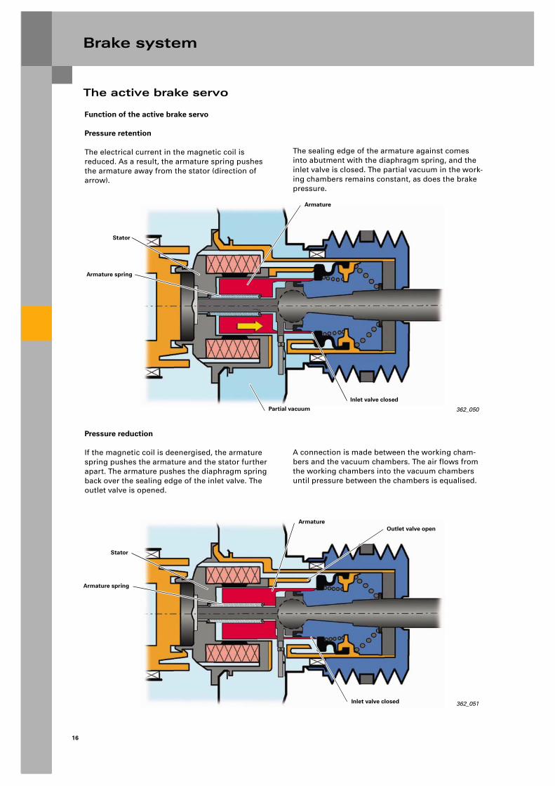
Pressure retention
The electrical current in the magnetic coil is reduced. As a result, the armature spring pushes the armature away from the stator (direction of arrow).
Pressure reduction
If the magnetic coil is deenergised, the armature spring pushes the armature and the stator further apart. The armature pushes the diaphragm spring back over the sealing edge of the inlet valve. The outlet valve is opened.
A connection is made between the working cham-bers and the vacuum chambers. The air flows from the working chambers into the vacuum chambers until pressure between the chambers is equalised.
362_050
Stator
Partial vacuum
Inlet valve closed
Armature spring
Armature
362_051
Stator
Inlet valve closed
Armature spring
ArmatureOutlet valve open
The sealing edge of the armature against comes into abutment with the diaphragm spring, and the inlet valve is closed. The partial vacuum in the work-ing chambers remains constant, as does the brake pressure.

17
ESP
Overview
A new ESP unit by Continental-Teves with the desig-nation Mk25E1 is used in the Audi Q7.
The differences between the Mk25E1 and the cur-rent Mk60IS ESP unit employed in the current Audi A3 are as follows:
Definition of the designation Mk25E1:
Mk25 = name of model series
E = use of linearised switch valves* as changeover valves (2x) and inlet valves (4x)
1 = use of an integrated pressure sensor
Reference
Mode of operation: refer to SSP 285
362_052
– Extended functions
– Uprated hydraulic pump
– More powerful electric motor
– Larger internal reservoirs
– Active engine speed sensors with forward/reverse travel detection and installation position recognition
18
ESP
Function overview
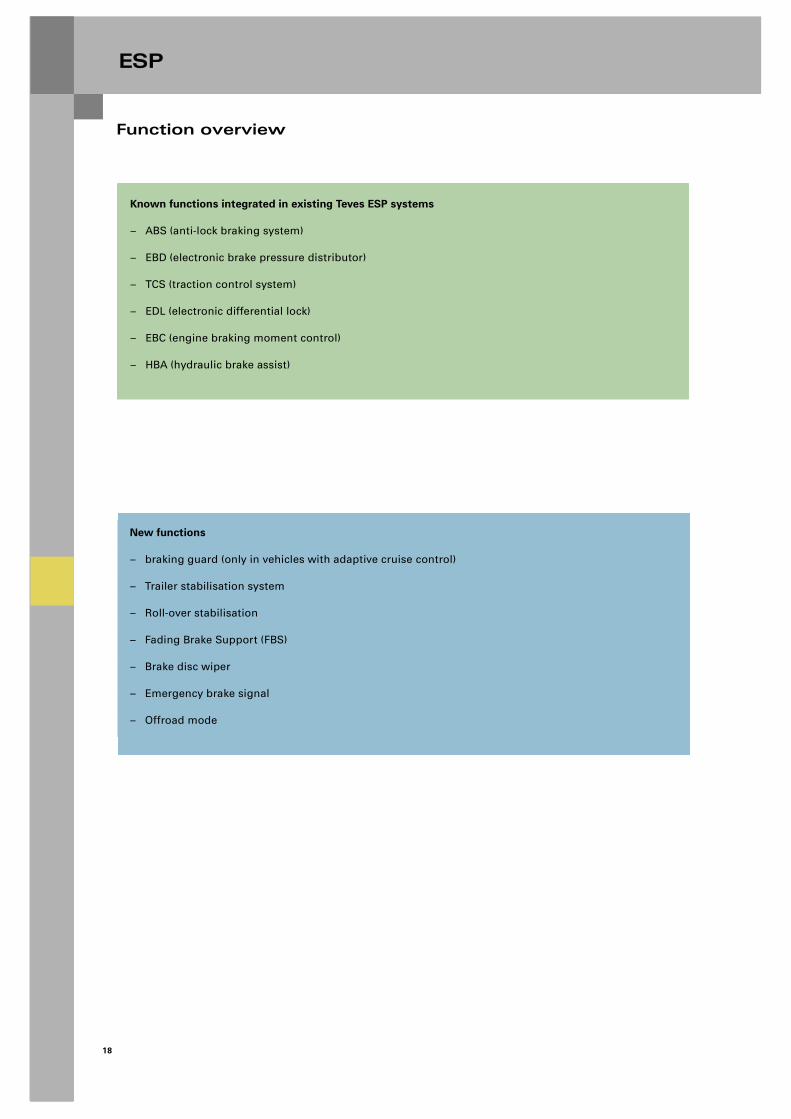
Known functions integrated in existing Teves ESP systems
– ABS (anti-lock braking system)
– EBD (electronic brake pressure distributor)
– TCS (traction control system)
– EDL (electronic differential lock)
– EBC (engine braking moment control)
– HBA (hydraulic brake assist)
New functions
– braking guard (only in vehicles with adaptive cruise control)
– Trailer stabilisation system
– Roll-over stabilisation
– Fading Brake Support (FBS)
– Brake disc wiper
– Emergency brake signal
– Offroad mode
19
New functions
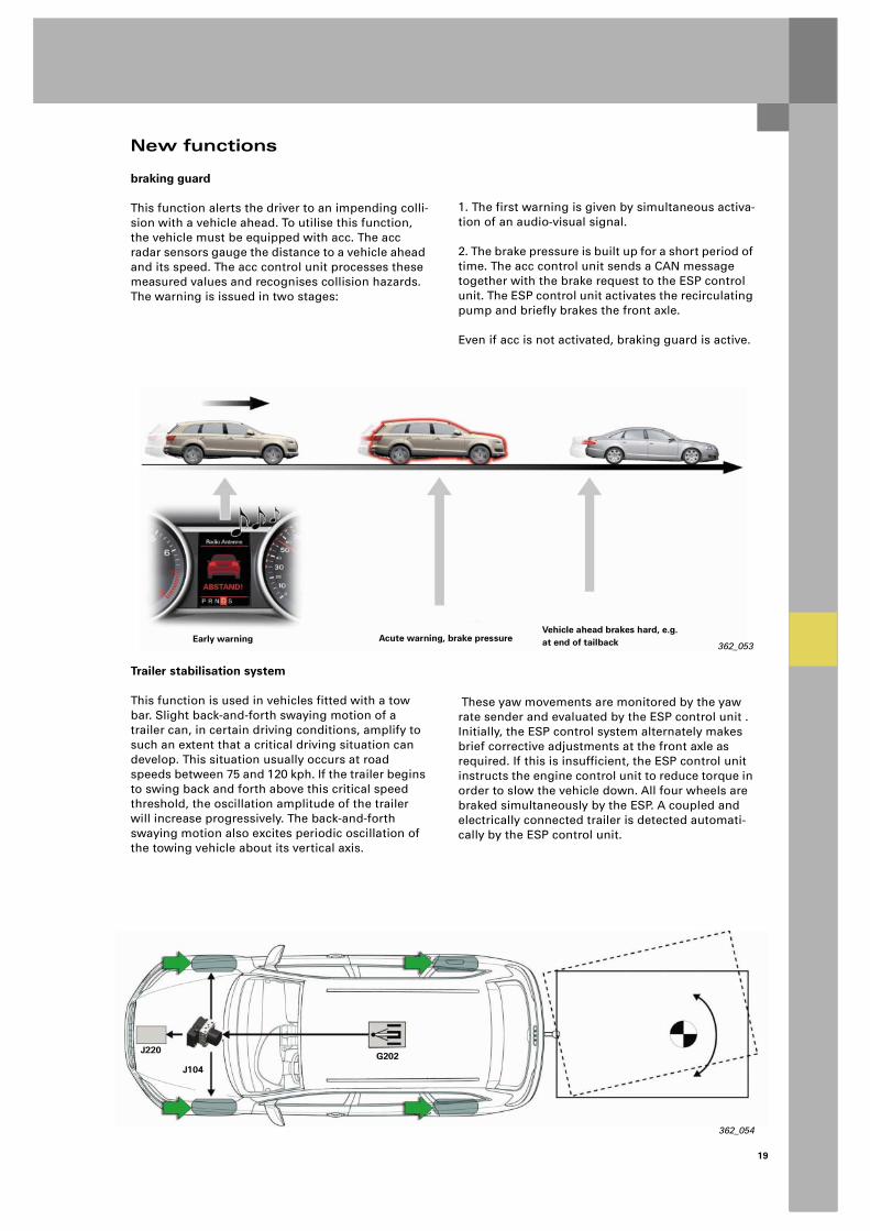
braking guard
This function alerts the driver to an impending colli-sion with a vehicle ahead. To utilise this function, the vehicle must be equipped with acc. The acc radar sensors gauge the distance to a vehicle ahead and its speed. The acc control unit processes these measured values and recognises collision hazards. The warning is issued in two stages:
1. The first warning is given by simultaneous activa-tion of an audio-visual signal.
2. The brake pressure is built up for a short period of time. The acc control unit sends a CAN message together with the brake request to the ESP control unit. The ESP control unit activates the recirculating pump and briefly brakes the front axle.
Even if acc is not activated, braking guard is active.
These yaw movements are monitored by the yaw rate sender and evaluated by the ESP control unit . Initially, the ESP control system alternately makes brief corrective adjustments at the front axle as required. If this is insufficient, the ESP control unit instructs the engine control unit to reduce torque in order to slow the vehicle down. All four wheels are braked simultaneously by the ESP. A coupled and electrically connected trailer is detected automati-cally by the ESP control unit.
362_053Early warning Acute warning, brake pressure
Vehicle ahead brakes hard, e.g. at end of tailback
362_054
J220
J104G202
Trailer stabilisation system
This function is used in vehicles fitted with a tow bar. Slight back-and-forth swaying motion of a trailer can, in certain driving conditions, amplify to such an extent that a critical driving situation can develop. This situation usually occurs at road speeds between 75 and 120 kph. If the trailer begins to swing back and forth above this critical speed threshold, the oscillation amplitude of the trailer will increase progressively. The back-and-forth swaying motion also excites periodic oscillation of the towing vehicle about its vertical axis.

20
ESP
New functions
Roll-over stabilisation
If the vehicle is in danger of rolling over, it is stabi-lised by reducing the lateral acceleration. This is achieved by massive corrective braking at the front axle. In addition, engine torque is reduced. The driver may notice some intervention, but will not yet have registered the critical driving situation (as of approx. 0.6g lateral acceleration). The ESP warning lamp flashes while ESP is active.
Emergency brake signal
The flashing warning lamps are activated during braking operations involving very high rates of deceleration or braking operations in the ABS oper-ating range.
Brake pressure is built up by activating the active brake servo and through active pressure build-up by the ESP. The active brake servo provides rapid pres-sure build-up on the intake side of the ESP recircu-lating pump. This enables the ESP to build up brake pressure very quickly.
Fading Brake Support (FBS)
If braking performance decreases due to low coeffi-cients of friction between the lining and the brake disc, the ESP pump builds up additional pressure to compensate for the loss of brake pressure.
This is the case when a high brake pressure is meas-ured, but the conditions at the wheels are outside the intervention range of the ESP. The FBS function is deactivated as soon as the driver reduces the brake pressure considerably. This is not indicated.
362_055
Braking torque
Pedal force
Nominal curve without fading
Actual curve with fading and without ESP assistance
Braking torque produced by the ESP

21
New functions
Brake disc wiper
If a speed signal greater than 50 kph and a wind-screen wiper command (incl. also when the wiper is in intermittent mode) are present on the CAN bus, the front brake pads are applied to the brake discs approx. every 3 km for a duration of approx. 8 sec-onds in order to remove any water film from the brake discs.
For this purpose, the ESP starts up and applies a pressure of approx. 0.8-1.2 bar. The function is not indicated to the driver. The func-tion interval is reset whenever the brake is applied.
362_056
Vehicle speed V > 50 kph
Windscreen wiper actuation (including intermittent mode)
J104
Active brake pressure build-up at the front axle
362_066
Time / distance
Brake pressure [bar]
3 km
8 s
1.2 bar
0.8 bar
22
ESP
New functions
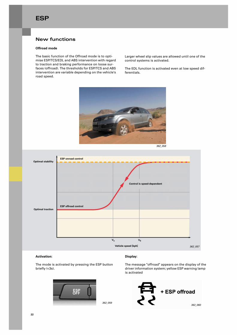
Offroad mode
The basic function of the Offroad mode is to opti-mise ESP/TCS/EDL and ABS intervention with regard to traction and braking performance on loose sur-faces (offroad). The thresholds for ESP/TCS and ABS intervention are variable depending on the vehicle's road speed.
Larger wheel slip values are allowed until one of the control systems is activated.
The EDL function is activated even at low speed dif-ferentials.
362_057
Optimal stability
Optimal traction
Vehicle speed [kph]
Vu V0
ESP onroad control
Control is speed-dependent
ESP offroad control
Activation:
The mode is activated by pressing the ESP button briefly (<3s).
362_059362_060
Display:
The message "offroad" appears on the display of thedriver information system; yellow ESP warning lamp is activated
362_058

23
New functions
Offroad mode
– The trailer stabilisation system is deactivated, because oscillation of the trailer would otherwise be erroneously detected incorrectly due to the offroad surface conditions.
362_061
– Activation of "ABS while reversing"
If the vehicle is rolling backwards down a slope, the rear axle is braked less than the front axle by the EBD function. While the vehicle is reversing, the rear axle is now treated like a front axle from a braking viewpoint, and a greater brake pressure is applied to the rear axle.
362_062
– Activation of the "hill descent assist" system;
The hill descent assist system assists the driver through brake activation in steep falling terrain with gradients of approx. 10-15% and at speeds up to 20 kph. The function is activated if different wheel speeds occur while driving downhill due to slippery surfaces or wheels lifting off the ground due to axle articulation on very uneven terrain. The objective is to enable the vehicle to negotiate the incline at a constant speed without any inter-vention by the driver.
362_063
Note
It is not possible to deactivate the ESP system in Offroad mode by pressing the ESP button.

24
ESP
System components
Hydraulic unit and control unit
Compared to the Mk60, an uprated hydraulic pump is employed for the hydraulic unit. Thus, in combi-nation with a more powerful electric motor, larger amounts of brake fluid can be conveyed in the same time. This is a necessary feature because the brake calipers in the Q7 have a much higher volumetric capacity than the brake calipers in previous Audi models.
Accordingly, the internal reservoirs have also been enlarged compared to the Mk60. The control unit is bolted to the hydraulic unit in the usual manner. The terminal pin assignments are identical to those of the Mk60 series.
362_052
Speed sensors
Active speed sensors are used in the Q7.
The advantage of these sensors is that they can detect forward/reverse travel, as well as the installa-tion position.The sensors utilise the Hall effect.
Reference
For detailed information on the design and mode of operation, please refer to SSP 285
362_080

25
System components
Brake light suppression relay
Activation of the solenoid of the active brake servo produces slight movements of the brake pedal with-out action by the driver. Thus, the brake light switch is actuated. The switching of the brake light switch is read in by the engine control unit. The engine control unit then instructs the convenience system central control unit J393 to activate the brake lights. Control unit J393 receives the signal simultaneously from the brake light switch along a discrete line.
Control unit J393 activates the brake lights if the CAN message and/or the discrete signal is/are present. However, the brake servo is also activated during corrective braking operations in which the brake light is not to be activated. In these cases, the relay suppresses transmission of the discrete sig-nal. For this purpose, the ESP control unit switches the relay and signals to the engine control unit that it should not activate the brake lights.
362_065
F47
J104
J220
J533
J393
J508
Convenience CAN
Powertrain CAN
Message to J220 to suppress brake light activation
Brake lights
Brake pedal
F
J220 Motronic control unitJ104 ESP control unitJ53 Data bus diagnostic interfaceJ393 Convenience system central control unitJ508 Brake light suppression relayF47 Brake pedal switchF Brake light switch
Note
The brake light suppression relay is not included in the system diagnostics.

26
ESP
Service work
New service procedures:
Encoding of the control unit
The following information is encoded:– Brake equipment– Suspension variant (aas or conventional suspen-
sion)– Engine variant– Towing attachment (not in USA)
Final control diagnostics
As the last step in the final control diagnostics, all valves required for EDL operation and the ESP pump are activated. All wheels on the vehicle must be braked if the valves are functioning properly.
Data blocks
The following measured values have been imple-mented in addition to the values known from the Audi A6:– Status of brake pressure solenoid trip switch F84
(in place of brake light switch signal)– Trailer detector– Status of handbrake (foot-operated handbrake)
In the Q7 too, the coding of the ESP control unit is checked by comparing the encoding information to the information stored in the airbag control unit. The information on drivetrain type and brake equip-ment is compared during each initialisation (termi-nal 15 ON).

27
Steering / wheels and tyres
Steering wheelsThe design and function of the steering wheels have been adopted from the current Audi A6. The geometric shape of the airbag gas ducts was adapted.
Steering systemA conventional hydraulic steering system with rotary vane pump, rotary slide valve and rack-and-pinion steering gear is used. Depending on engine variant, steering pumps with various delivery rates are used (11cm3/revolution for V6 engines, 14 cm3/revolution for V8 engines.
362_064362_069
The programme includes three-spoke and four-spoke steering wheels. These steering wheels are optionally available with a leather cover, multi-func-tion buttons, Tiptronic and heated steering wheel rim.
The servotronic function is standard. The Servotronic II from the current Audi A8 is employed (see SSP 285). The servotronic solenoid valve is activated by onboard power supply control unit -2- J520.
Steering columnA mechanically adjustable steering column is offered as standard equipment. The steering col-umn has the same multi-disc clamping system as the steering columns used in the Audi A8 and Audi A6 (see SSP 285). The steering columns of the Q7 are also equipped with an electrical steering lock.
The steering lock has the same design and mode of operation as the steering column used in the A6. In the Q7, the complete structural unit is also attached unseparably to the steering column for reasons of anti-theft protection.
An electrical steering column is offered as optional equipment. The electrical drives have been adopted from the steering column used in the Audi A8.
362_034a
362_034b
Overview

28
Steering / wheels and tyres
Wheels overview
Tyre pressure check system
A tyre pressure check system is available as optional equipment for the Q7. The tyre pressure check sys-tem has the same design and mode of operation as the system used in the Audi A6.
Reference
For detailed information on the design and mode of operation, please refer to SSP 326
362_035
Engine
6-cylinder
8-cylinder
Basic wheels Optional 18" wheels Optional 19" wheels Optional 20" wheels Winter wheels
7.5J x 18 ET 53 (1) aluminium forged wheel painted235/60 R 18
8J x 18 ET 56 (3) aluminium forged wheel polished255/55 R 18
8.5J x 19 ET 62 (5) aluminium cast wheel painted265/50 R 19
9J x 20 ET 60 (6) aluminium cast wheel polishedbicolor275/45 R 20
7.5J x 18 ET 53 (1) aluminium forged wheel painted235/60 R 18
8J x 18 ET 56 (2) alu-minium forged wheel painted255/55 R 18(available as optional equipment for 6-cylinder)
8.5J x 18 ET 58 (4) aluminium cast wheelpainted255/55 R 18

29
adaptive air suspension (aas)
Overview
The aas system in the Q7 is based on the system in the VW Touareg. With the exception of the springs and dampers, the axle components are identical to those of the steel-sprung suspension. The produc-tion control number (PR number) for the aas is 1BK.
Air supply unitwith solenoid valve block
Body acceleration sender, front right G342
Front right vehi-cle level sender G289
Front axle air sus-pension damper
Vehicle level sender, front left G78
Body acceleration sender, front left G341
Pressure accu-mulator 1
Rear axle air damper
Body acceleration sender,rear G343
Adaptive suspension control unit J197
Pressure accumulator 2
Vehicle level sender, rear G76, G77
Adaptive suspension button E388 (in luggage compartment)
362_001

30
adaptive air suspension (aas)
362_002
Diagnostic connection
J285 Control unit with display in dash panel insert
J533 Data bus diagnostic interface
J220 Motronic control unit
J104 ESP control unit
J431 Headlight range con-trol, control unit
J527 Steering column electronics control unitG85 Steering angle sender
J523 Front information control unit
J518 Entry and start authori-sation control unit
J345 Trailer detection control unit
J197 Adaptive suspension control unit
Powertrain CAN bus
Dash panel insert CAN
Most bus
Convenience CAN
Diagnostics CAN
Overview
System overview of networked components

31
Overview
System overview of non-networked components
362_003
G76, G77, G78, G289 Vehicle level sender
E388 Adaptive suspen-sion button
G290 Compressor temper-ature sender
G291 Pressure sender (inte-grated in solenoid valve block)
G341, G342, G343 Body acceleration senders
J393 Door and flap actuation signals from conven-ience system central control unit
J403 Adaptive suspension compressor relay
N311 Adaptive suspension pressure accu-mulator valve in solenoid valve block
N148, N149, N150, N151 Sus-pension strut valves in solenoid valve block
N111 Adaptive suspension drain valve (integrated in the air supply unit)
Input signals Output signals
N336, N337, N338, N339 Shock absorber damping adjustment valves (component part of the spring damper)
J197 Adaptive suspen-sion control unit

32
adaptive air suspension (aas)
Overview
Differences in design to the aas system in the Audi A6:
– Use of two pressure accumulators instead of one– Larger air supply line cross-sections (Ø8mm
instead of Ø6mm)– All air lines are moulded parts, and not integrated
the wiring harness– Partially modified design of the system compo-
nents (due to different manufacturer)
Differences in mode of operation to the aas system in the Audi A6:
– Additional mode: "offroad"– Additional lowering of the rear axle by 45 mm
below normal level for greater ease of loading– Modified control strategy– Modified operating and display elements
System components
Control unit J197
The control unit is located in the rack in the luggage compartment on the right. The control unit deter-mines from the input signals the necessary signals for activating the damping valves, the compressor, the pneumatic switch valves and the driver informa-tion displays. The adaptive suspension control unit has the same geometry and design as the control unit used in the Audi A8.An additional input signal compared to A8 and A6 is the signal from the adaptive suspension button E388 in the luggage compartment for lowering the vehicle rear end in "load" mode.
362_004

33
System components
Air suspension damper
Air suspension damper are used on the front and rear axles for the Q7. The spring/damper configura-tion is not separate like in the A6. The air suspension dampers are identical in design and function to the dampers in the VW Touareg. The roll piston geometry and the damper setup were modified for use in the Q7.
362_005
Residual pressure maintaining valve
Damper
Air spring outerguide
Air spring boot
Boot
Auxiliary spring
Roll piston
CDC valve
Rear axle air suspension damper
362_006
Spring damper bearing
Damper
Air spring-Outer guide
Air spring boot
Boot
Residual pressure maintaining
Roll piston
CDC valve
Auxiliary spring
The residual pressure maintaining valves ensure that a minimum pressure of approximately 3.5 bar is maintained in the air springs even if a major leak occurs in the system.

34
adaptive air suspension (aas)
System components
Air suspension damper CDC valve
A CDC valve (CDC = continuous damping control) is used for the damping control. The fundamental dif-ference to the CDC valve used in the A8 is that the valve in the Q7 is attached to the exterior of the damper tube.
Mode of operation
If the CDC valve is not energised, the valve gate and cylinder are fixed in the position illustrated by the spring forces. In this position, damper oil can drain through a defined port cross section from the pis-ton chamber to the equalising chamber (=medium damping forces).
The armature is shifted by applying current to the magnetic coil. Thus, the port cross sections for the damper oil change. Large cross-sections, and hence low damping forces, are achieved at low activation currents (as of approx. 600 mA). High damping forces are set when the damper is activated by applying a high current (from approx. 1000 mA to approx. 2000 mA) .
362_008
Oil flow
Armature
Magnetic coil
Piston valve
Bottom valve
Note
In the event of a system fault, the valve is deen-ergised. Thus, medium damping forces are set and the vehicle maintains driving stability.

35
System components
Air suspension damper CDC valve
The air supply unit together with the valve block is attached to a common mounting bracket on the vehicle floorpan at the front right. The design and mode of operation of the air suspension damper CDC valve are identical to the unit used in the VW Touareg. The Q7 does not have a tyre inflation con-nection.
The maximum system pressure is 16.5 bar. The max-imum operating time of the compressor is deter-mined by its temperature, which is monitored permanently by a sender, like in the A6 and A8.
362_007
Vibrationinsulator
Air drier Compressor
Compressor tempera-ture sender
Solenoid valve block
Vibration isolator
Electric motor
Pneumatic drain valve

36
adaptive air suspension (aas)
System components
Pressure accumulators
The pressure accumulators have the following func-tions:
– Implementation of control actions (raising the vehicle level) without activating the compressor, thereby improving the quality of the interior acoustics, reducing the compressor temperature and increasing the availability of the compressor function.
– Vehicle level correction after occupants exit the vehicle, after 2, 5 and 10 hours depending on requirements.
– Due to much greater air volume in the system, two pressure accumulators are used in the Q7, instead of one like in the A6 and A8.
362_001a
Pressure accumulator 2
Pressure accumulator 1
The pressure accumulator is made of aluminium. The storage volumes of the front/rear accumulators are 5.2l / 4.8 l. A control operation can only be performed with the accumulator if the air pressure in the accumulator is 3 bar greater than the air pressure in the partici-pating air spring.
If the air pressure in the pressure accumulator drops to approximately 12.3 bar while the system is active and with the vehicle's engine running and the vehicle travelling at a speed of greater than 35 kph, the compressor starts up and charges the accumu-lator.

37
System components
Sensors
The vehicle level and the acceleration of the uns-prung masses are measured by the vehicle level sender, like in the A8 and A6.
The senders are identical to those used in the A8 and VW Touareg.
362_079
Like in the A8 and A6, the body acceleration sender are used to measure vehicle body acceleration (acceleration of the sprung masses). The senders are identical to those used in the A8 and VW Touareg.
Two senders are installed in the wheel arches at the right left and right. A third sender is located in the vehicle interior at the rear left, at rear axle level.
362_077
38
adaptive air suspension (aas)
Vehicle ride heights
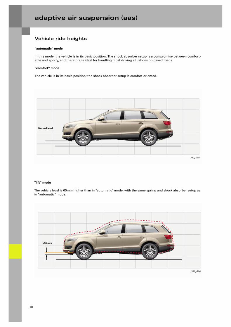
"automatic" mode
In this mode, the vehicle is in its basic position. The shock absorber setup is a compromise between comfort-able and sporty, and therefore is ideal for handling most driving situations on paved roads.
"comfort" mode
The vehicle is in its basic position; the shock absorber setup is comfort-oriented.
362_015
Normal level
362_016
+60 mm
"lift" mode
The vehicle level is 60mm higher than in "automatic" mode, with the same spring and shock absorber setup as in "automatic" mode.
39
Vehicle ride heights
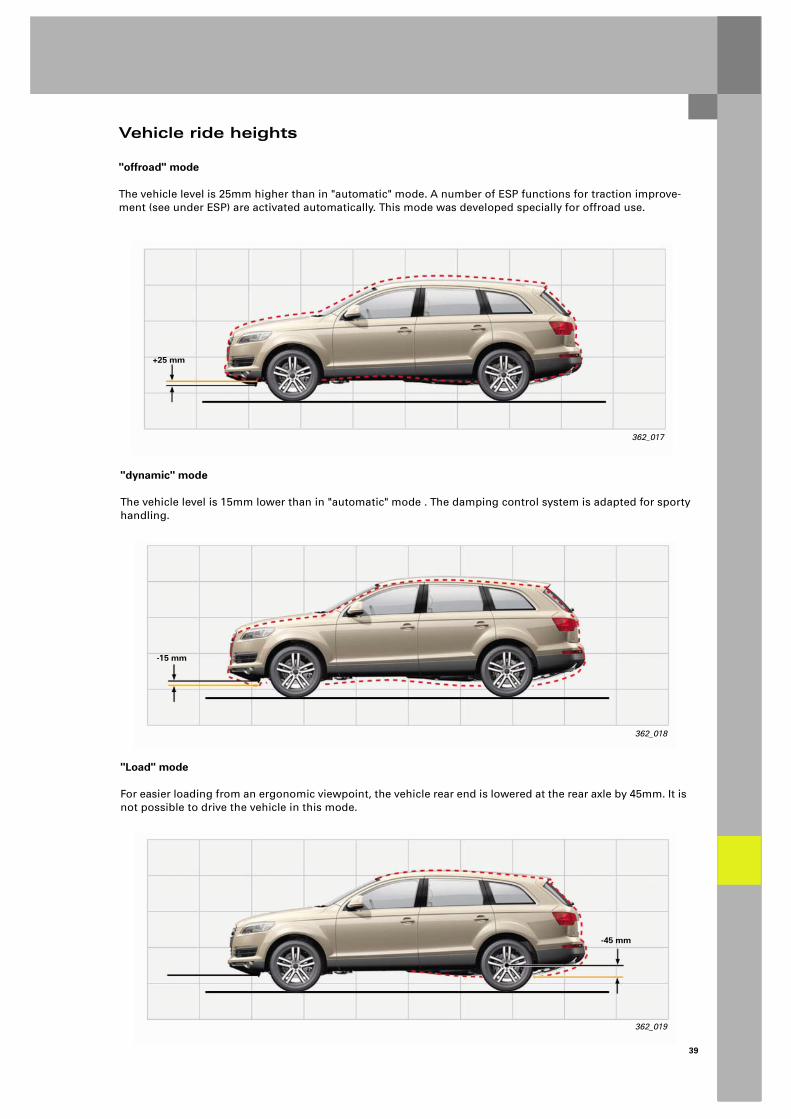
"offroad" mode
The vehicle level is 25mm higher than in "automatic" mode. A number of ESP functions for traction improve-ment (see under ESP) are activated automatically. This mode was developed specially for offroad use.
362_017
+25 mm
"dynamic" mode
The vehicle level is 15mm lower than in "automatic" mode . The damping control system is adapted for sporty handling.
362_018
-15 mm
"Load" mode
For easier loading from an ergonomic viewpoint, the vehicle rear end is lowered at the rear axle by 45mm. It is not possible to drive the vehicle in this mode.
362_019
-45 mm

40
adaptive air suspension (aas)
Vehicle levels - modes
"Load" mode
The "Load" mode can be activated with the MMI or the button in the rear of the vehicle.
The function:
– can only be activated with the MMI if all doors are closed
362_020
User Setup Car Vehicle wallet
Adaptive air suspension
Lower for loading
Trailer operation
Car jack mode
Systems 12:00 AM VersionTP TMC
ON
ON
362_021
Lift vehicle
Lower vehicle
– can only be activated by button if all doors are closed and the tailgate is open
362_022
User Car Vehicle wallet
Adaptive air suspension
lift
off road
comfort
Systems Service
automatic
dynamic
To illustrate the active "load" mode, the vehicle sym-bol is replaced by the symbol shown here.
No bars are shown because the loading height is below the level which occurs during vehicle opera-tion.
362_023
User Car Vehicle wallet
Adaptive air suspension
comfort
Systems Service
automatic
dynamic
10:25 AM
41
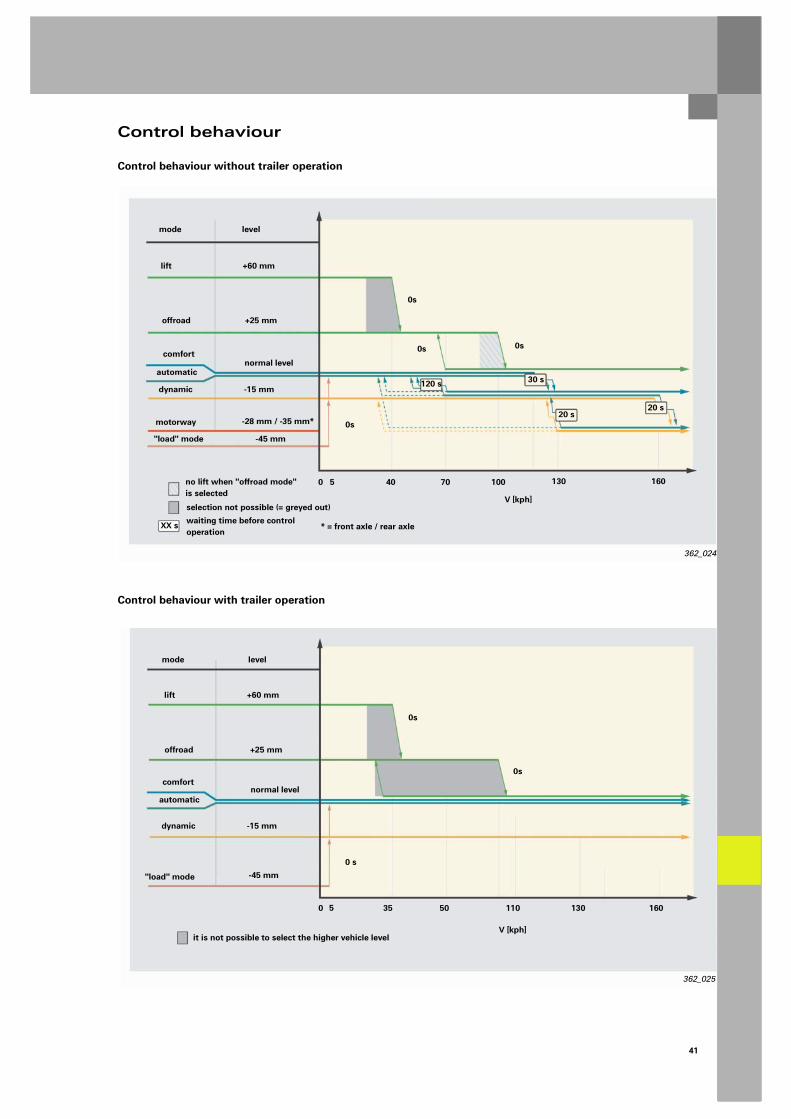
Control behaviour
Control behaviour without trailer operation
362_025
V [kph]
mode
0 5 35 50 110 130 160
level
lift +60 mm
offroad +25 mm
comfortnormal level
automatic
dynamic -15 mm
"load" mode -45 mm
0s
0 s
0s
it is not possible to select the higher vehicle level
Control behaviour with trailer operation
362_024
V [kph]
mode
0 5 40 70 100 130 160
level
lift +60 mm
offroad +25 mm
comfortnormal level
automatic
dynamic -15 mm
motorway -28 mm / -35 mm*
"load" mode -45 mm
30 s
20 s
0s 0s
0s
0s
waiting time before control operation
no lift when "offroad mode" is selected
selection not possible (= greyed out)
* = front axle / rear axle
20 s
120 s
XX s
42
adaptive air suspension (aas)
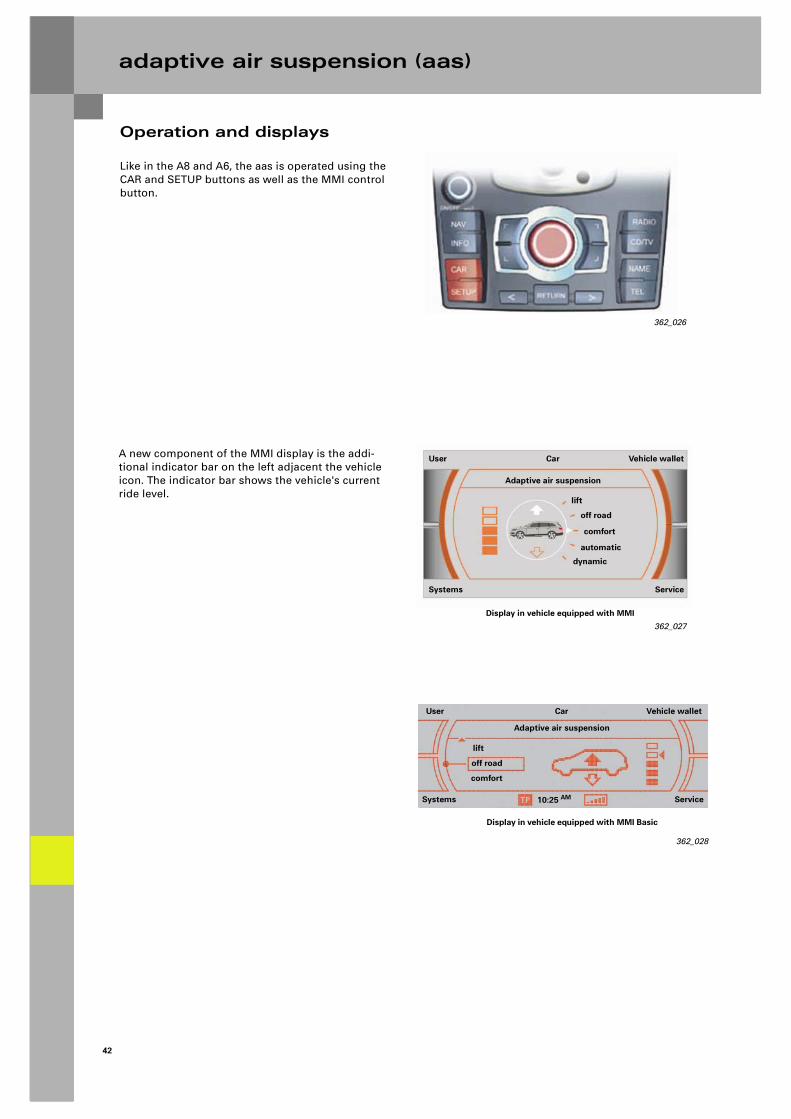
Operation and displays
Like in the A8 and A6, the aas is operated using the CAR and SETUP buttons as well as the MMI control button.
A new component of the MMI display is the addi-tional indicator bar on the left adjacent the vehicle icon. The indicator bar shows the vehicle's current ride level.
362_027
User Car Vehicle wallet
Adaptive air suspension
lift
off road
comfort
Systems Service
automatic
dynamic
Display in vehicle equipped with MMI
362_028
User Car Vehicle wallet
Adaptive air suspension
Systems Service10:25 AM
lift
off road
comfort
Display in vehicle equipped with MMI Basic
362_026

43
Like in the A8 and A6, there are two warning lamps in the dash panel insert. The following states are indicated:
Yellow warning lamp (continuous):– in load mode– in car jack mode (ride height control deactivated)– in the event of system faults– vehicle level extremely high (as of 80mm above
normal level, warning lamp flashes)– during final control test and basic adjustment in
service workshop
Green lamp:– loading height activated– dynamic driving mode was selected (display
duration: approx. 15 s)– extreme payload from 25mm below normal level
(except in "dynamic" mode)
Both lamps (flashing): – vehicle under extreme load (from 65mm below
normal level)
362_031
Operation and displays
A new feature is the temporary display in the centre display of the dash panel insert.The indicator bar, the target marker and the control arrows are activated in the same way as on the MMI display.This display can be selected manually with the Reset key on the wiper stalk.
Display is automatic when:
– offroad mode is selected– lift mode is selected– the aas exits lift mode automatically when the
speed threshold is exceeded
362_030
RADIO IN
+ 2.5°C
Display in vehicle equipped with midline and lowline dash panel insert
362_029Display in vehicle equipped with highline dash panel insert

44
adaptive air suspension (aas)
J197
Function diagram
J197 Adaptive suspension control unitG76 Vehicle level sender, rear leftG77 Vehicle level sender, rear rightG78 Vehicle level sender, front leftG289 Vehicle level sender, front rightG290 Compressor temperature senderG291 Adaptive suspension pressure senderJ393 Convenience system central control unit
(for doors signal)G341 Body acceleration sender, front leftG342 Body acceleration sender, front rightG343 Body acceleration sender, rearJ403 Adaptive suspension compressor relayN111 Adaptive suspension drain valveN148 Suspension strut valve, front leftN149 Suspension strut valve, front rightN150 Suspension strut valve, rear leftN151 Suspension strut valve, rear right
N311 Adaptive suspension pressure accumulator valveN336 Damper adjustment valve, front leftN337 Damper adjustment valve, front rightN338 Damper adjustment valve, rear leftN339 Damper adjustment valve, rear rightV66 Adaptive suspension compressor motorE388 Adaptive suspension button

45
362_033
1 2
Colour codes
Input signal
Output signal
Positive supply
Earth
CAN bus
CAN-High CAN-Low
46
adaptive air suspension (aas)
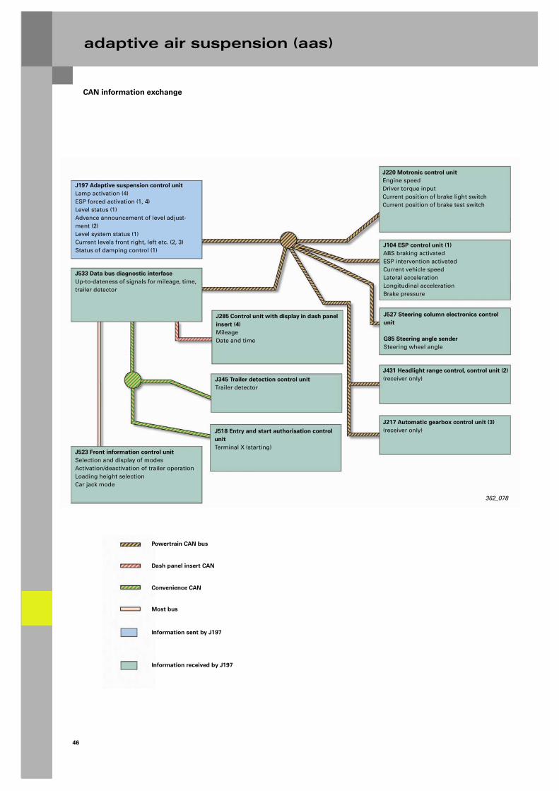
CAN information exchange
J197 Adaptive suspension control unitLamp activation (4)ESP forced activation (1, 4)Level status (1)Advance announcement of level adjust-ment (2)Level system status (1)Current levels front right, left etc. (2, 3)Status of damping control (1)
J533 Data bus diagnostic interfaceUp-to-dateness of signals for mileage, time, trailer detector
J523 Front information control unit Selection and display of modesActivation/deactivation of trailer operationLoading height selectionCar jack mode
J285 Control unit with display in dash panel insert (4)MileageDate and time
J345 Trailer detection control unit Trailer detector
J518 Entry and start authorisation control unitTerminal X (starting)
J220 Motronic control unit Engine speed Driver torque inputCurrent position of brake light switchCurrent position of brake test switch
J104 ESP control unit (1)ABS braking activatedESP intervention activatedCurrent vehicle speedLateral accelerationLongitudinal accelerationBrake pressure
J527 Steering column electronics control unit
G85 Steering angle senderSteering wheel angle
J431 Headlight range control, control unit (2)(receiver only)
J217 Automatic gearbox control unit (3)(receiver only)
Powertrain CAN bus
Dash panel insert CAN
Convenience CAN
Most bus
Information sent by J197
Information received by J197
362_078

47
Service work
New service procedures:
1. Encoding control unit J197:
When a control unit is replaced or flashed, it must initially be encoded before a system initialisation can be performed.
3. System initialisation:
The vehicle ride heights are adapted in a modified procedure.
2. Final control test:
The pressure accumulator test is now performed; temperature and pressure gauge readings are dis-played.The warning lamps are no longer activated.
362_068
362_067

36
2
All rights reserved. Technical specifications subject to change without notice.
CopyrightAUDI AGI/[email protected] +49-841/89-36367
AUDI AGD-85045 IngolstadtTechnical status: 11/05
Printed in GermanyA05.5S00.15.20
Audi Q7 - Running Gear
Self-Study Programme 362
Vorsprung durch Technik www.audi.de Service Training