sst-2450 wireless modem user’s manual - protekna wireless modem user’s manual ver1.5, feb /2003,...
TRANSCRIPT
SST-2450 Wireless Modem User’s Manual Ver1.5, Feb /2003, OMH-030-10, ---1
SST-2450 Wireless Modem User’s Manual
Warranty
All products manufactured by ICP DAS are warranted against defective materials for a period of one year from the date of delivery to the original purchaser. Warning ICP DAS assumes no liability for damages consequent to the use of this product. ICP DAS reserves the right to change this manual at any time without notice. The information furnished by ICP DAS is believed to be accurate and reliable. However, no responsibility is assumed by ICP DAS for its use, or for any infringements of patents or other rights of third parties resulting from its use. Copyright Copyright 2002 by ICP DAS. All rights are reserved. Trademark
The names used for identification only may be registered trademarks of their respective companies.
SST-2450 Wireless Modem User’s Manual Ver1.5, Feb /2003, OMH-030-10, ---2
Table of Contents
1. Introduction...................................................................................................................3 2. Specifications ...............................................................................................................4 3. Product Description ......................................................................................................5
3.1. Pin assignment...............................................................................................5 3.2. Block diagram.................................................................................................6
4. Applications ..................................................................................................................7 4.1. Peer to Peer...................................................................................................7
4.1.1. PC to PC connections -- Using Mode 1..........................................8 4.1.2. Connecting a PC to the 7000 module – Using Mode 2...................9 4.1.3. 7188 Embedded Controller to 7000 module – Using Mode 3.......10 4.1.4. Connecting a PC to a PLC – Using Mode 3 ................................. 11 4.1.5. Using the 7188 as a Bridge -- Using Mode 3................................ 12
4.2. Network communication ...............................................................................13 4.2.1. Application 1.................................................................................13 4.2.2. Application 2.................................................................................14
5. Quick Start instructions for the SST-2450 ................................................................... 15 5.1. Installing the software ..................................................................................15 5.2. SST-2450 Setting.........................................................................................17 5.3. Testing the SST-2450 ..................................................................................19
6. Troubleshooting ..........................................................................................................20 7. Dimensions.................................................................................................................21 8. Din-rail Mounting.........................................................................................................22 9. External Antenna ........................................................................................................23
9.1. ANT-8 (Omni directional) .............................................................................23 9.2. ANT-15 (Omni directional) ...........................................................................24 9.3. ANT-21 (Directional) ....................................................................................25
10. Appendix ..……………………………………………………………………………………26
SST-2450 Wireless Modem User’s Manual Ver1.5, Feb /2003, OMH-030-10, ---3
1. Introduction SST-2450EXT is a spread spectrum radio modem with controlling an
RS-232/RS-485 interface port. It is designed for data acquisition and control
applications between a host and remote sensors. It is also useful for those
applications where the installation of cable wire is inconvenient. The
SST-2450 can be used not only in peer-to-peer mode (refer to page 8), but
also in a multi-point structure (refer to page 13).
The SST-2450 is based on a direct sequence spread spectrum and RF
technology, operating In the ISM bands with a Frequency Range of
2410.496MHz~2471.936MHz. The Channel Spacing is 4.096MHz.
The SST-2450 is similar to the SST-2400, with the major difference being
the setting control method. The SST-2400 is set using jumpers, whereas the
SST-2450 is set using a software utility. The older SST-2400 can work in
conjunction with the new SST-2450 by changing its internal 8051 chip. The
new chip includes updated firmware, so please contact us and we will send a
new chip. Refer to page 26 for detail.
SST-2450 Wireless Modem User’s Manual Ver1.5, Feb /2003, OMH-030-10, ---4
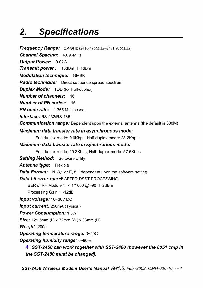
2. Specifications Frequency Range: 2.4GHz (2410.496MHz~2471.936MHz)
Channel Spacing: 4.096MHz Output Power: 0.02W
Transmit power : 13dBm 土 1dBm
Modulation technique: GMSK
Radio technique: Direct sequence spread spectrum Duplex Mode: TDD (for Full-duplex)
Number of channels: 16
Number of PN codes: 16
PN code rate: 1.365 Mchips /sec.
Interface: RS-232/RS-485 Communication range: Dependent upon the external antenna (the default is 300M)
Maximum data transfer rate in asynchronous mode:
Full-duplex mode: 9.6Kbps; Half-duplex mode: 28.2Kbps Maximum data transfer rate in synchronous mode:
Full-duplex mode: 19.2Kbps; Half-duplex mode: 57.6Kbps Setting Method: Software utility Antenna type: Flexible Data Format: N, 8,1 or E, 8,1 dependent upon the software setting Data bit error rate���� AFTER DSST PROCESSING:
BER of RF Module: < 1/1000 @ -90 土 2dBm
Processing Gain:~12dB
Input voltage: 10~30V DC
Input current: 250mA (Typical) Power Consumption: 1.5W Size: 121.5mm (L) x 72mm (W) x 33mm (H) Weight: 200g Operating temperature range: 0~50C Operating humidity range: 0~90%
SST-2450 can work together with SST-2400 (however the 8051 chip in the SST-2400 must be changed).
SST-2450 Wireless Modem User’s Manual Ver1.5, Feb /2003, OMH-030-10, ---5
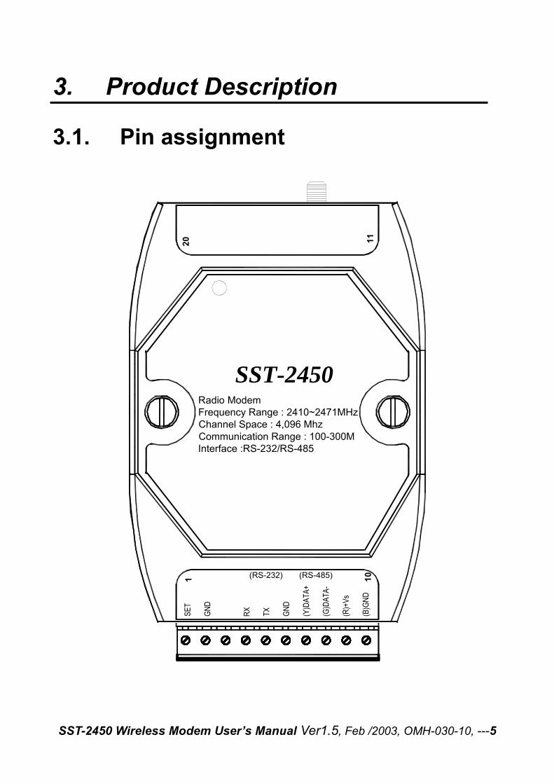
3. Product Description
3.1. Pin assignment
Radio ModemFrequency Range : 2410~2471MHzChannel Space : 4,096 MhzCommunication Range : 100-300MInterface :RS-232/RS-485
SST-2450
SE
T
GN
D
RX
TX
GN
D
(Y)D
AT
A+
(G)D
AT
A-
(R)+
Vs
(B)G
ND
(RS-232) (RS-485)1 10
20 11
SST-2450 Wireless Modem User’s Manual Ver1.5, Feb /2003, OMH-030-10, ---6
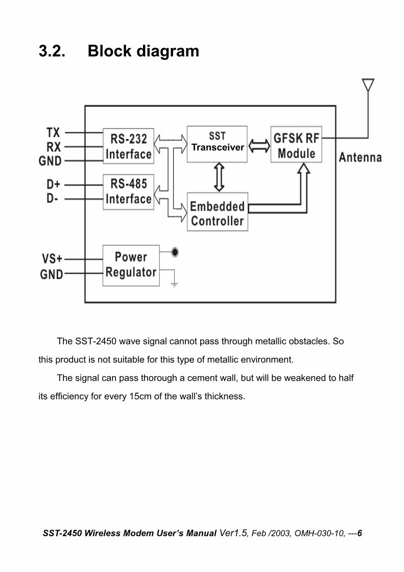
3.2. Block diagram
The SST-2450 wave signal cannot pass through metallic obstacles. So
this product is not suitable for this type of metallic environment.
The signal can pass thorough a cement wall, but will be weakened to half
its efficiency for every 15cm of the wall’s thickness.
Transceiver
SST-2450 Wireless Modem User’s Manual Ver1.5, Feb /2003, OMH-030-10, ---7
4. Applications 4.1. Peer to Peer
There are three types of peer to peer operational modes to choose from. The following table outlines the settings information and limitations. Mode Description:
1
In this mode, the SST-2450 can accept and transmit any signal from the device. This mode works by using a sample and rebuild. The SST module samples the input signal then converts it into a wave signal technique before transmitting it to another SST module. When the other SST module receives the wave signal, it transforms the signal back into the original format. The sample rate used is 32kb per second, so the device can’t accept higher speed signals. The maximum signal speed is less than 9600 bps. Any data format may be need in this mode. Setting Limitative: Baud Rate must be 9600bps or below; Full-duplex; Asynchronous; One SST-2450 is the Master the other is the Slave.
2
This mode simulates the Full-duplex mode. The device can transmit and receive signals at the same frequency. The RF processor uses the timer controller to simulate Full-duplex. Initially, the module that has been set as the master is in transmission mode. After 4ms, it switches to receive mode. The slave module is inverse to thus. For example if the master is in transmission mode but a signal need to be transmitted by the slave at the same time; the slave will store the signal in it’s buffer and will transmit once the master is in the receive mode. In Mode 2, the RF signal will be processed by the 8051 CPU so requires the fixed data format to be either N, 8,1 or E, 8,1. Setting Limitative: Full-duplex; Synchronous; One SST-2450 is the Master and the other is the Slave.
3
This mode simulates the Half-duplex mode. One device will respond when it receive a command from another device. This is the only mode which supports a SST-2450 network (refer to page 13). This mode is also requires a fixed data format to be either N, 8,1 or E, 8,1. Setting Limitative: Half-duplex; Synchronous; Both SST-2450s are slaves.
Refer to chapter 5 for further setting argument information.
SST-2450 Wireless Modem User’s Manual Ver1.5, Feb /2003, OMH-030-10, ---8
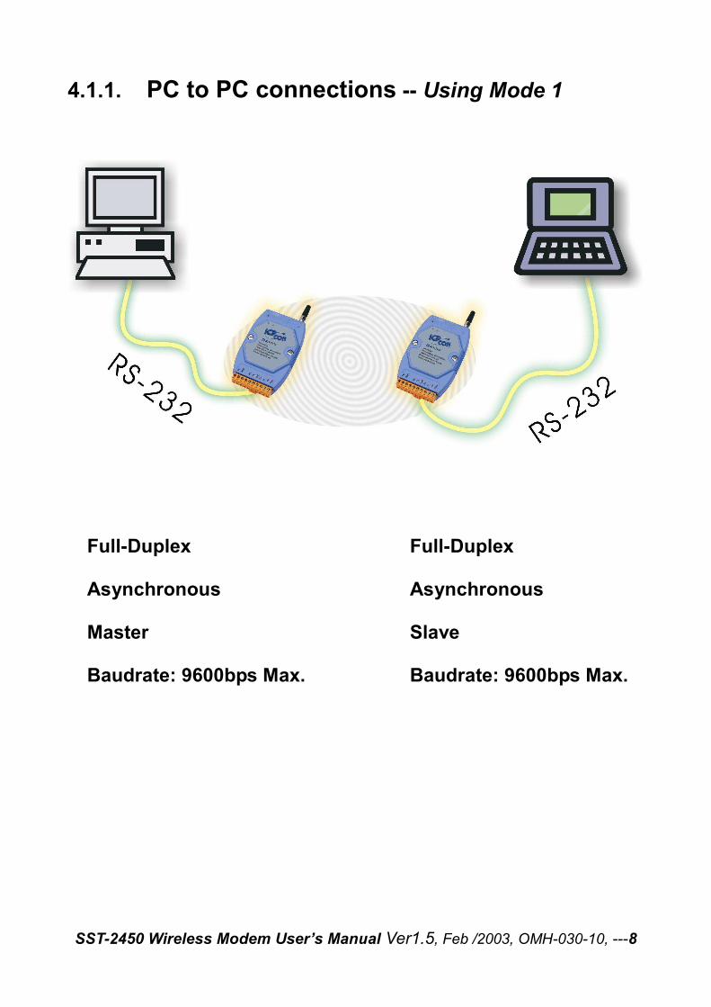
4.1.1. PC to PC connections -- Using Mode 1
Full-Duplex
Asynchronous
Master
Baudrate: 9600bps Max.
Full-Duplex
Asynchronous
Slave
Baudrate: 9600bps Max.
SST-2450 Wireless Modem User’s Manual Ver1.5, Feb /2003, OMH-030-10, ---9
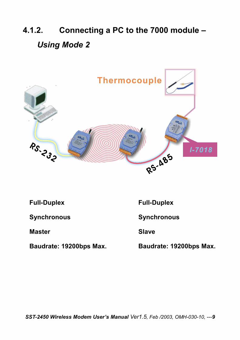
4.1.2. Connecting a PC to the 7000 module –
Using Mode 2
Full-Duplex
Synchronous
Master
Baudrate: 19200bps Max.
Full-Duplex
Synchronous
Slave
Baudrate: 19200bps Max.
SST-2450 Wireless Modem User’s Manual Ver1.5, Feb /2003, OMH-030-10, ---10
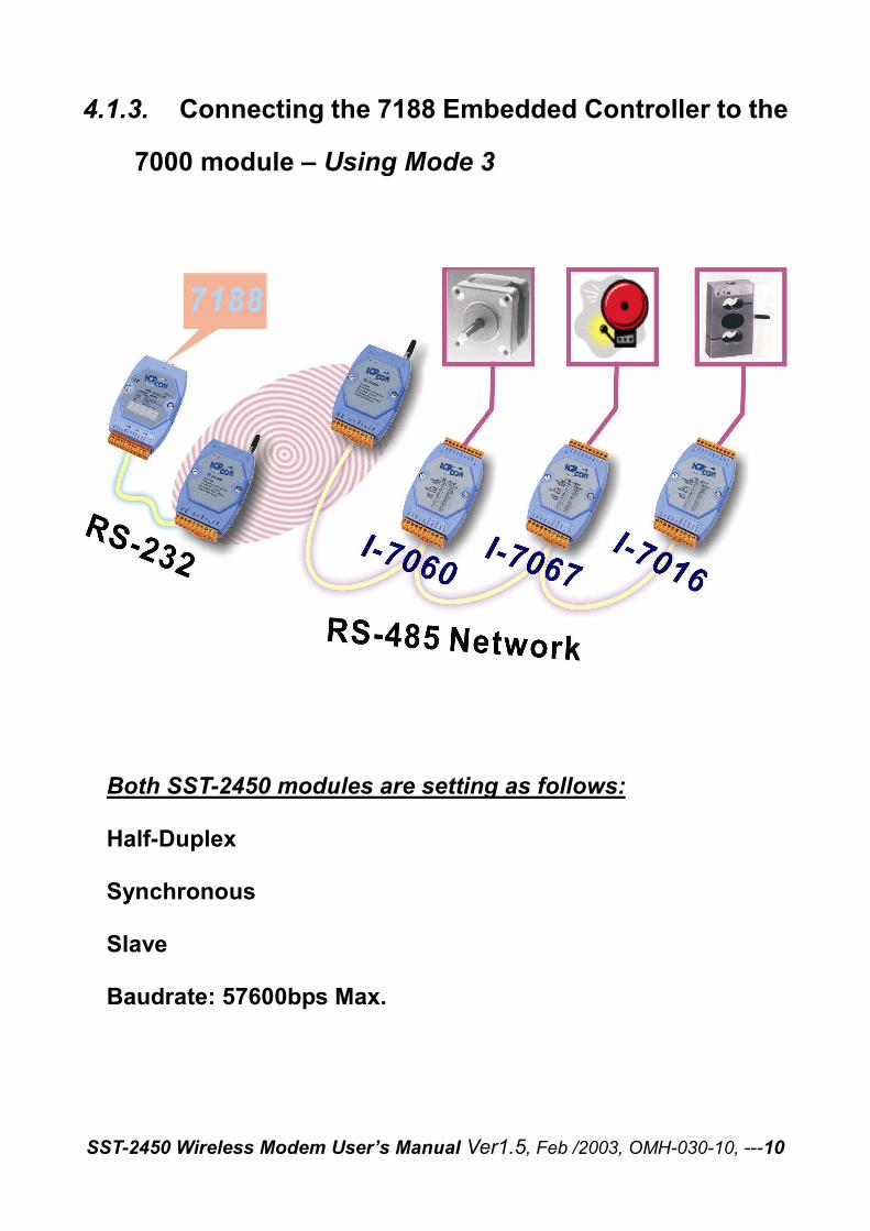
4.1.3. Connecting the 7188 Embedded Controller to the
7000 module – Using Mode 3
Both SST-2450 modules are setting as follows:
Half-Duplex
Synchronous
Slave
Baudrate: 57600bps Max.
SST-2450 Wireless Modem User’s Manual Ver1.5, Feb /2003, OMH-030-10, ---11
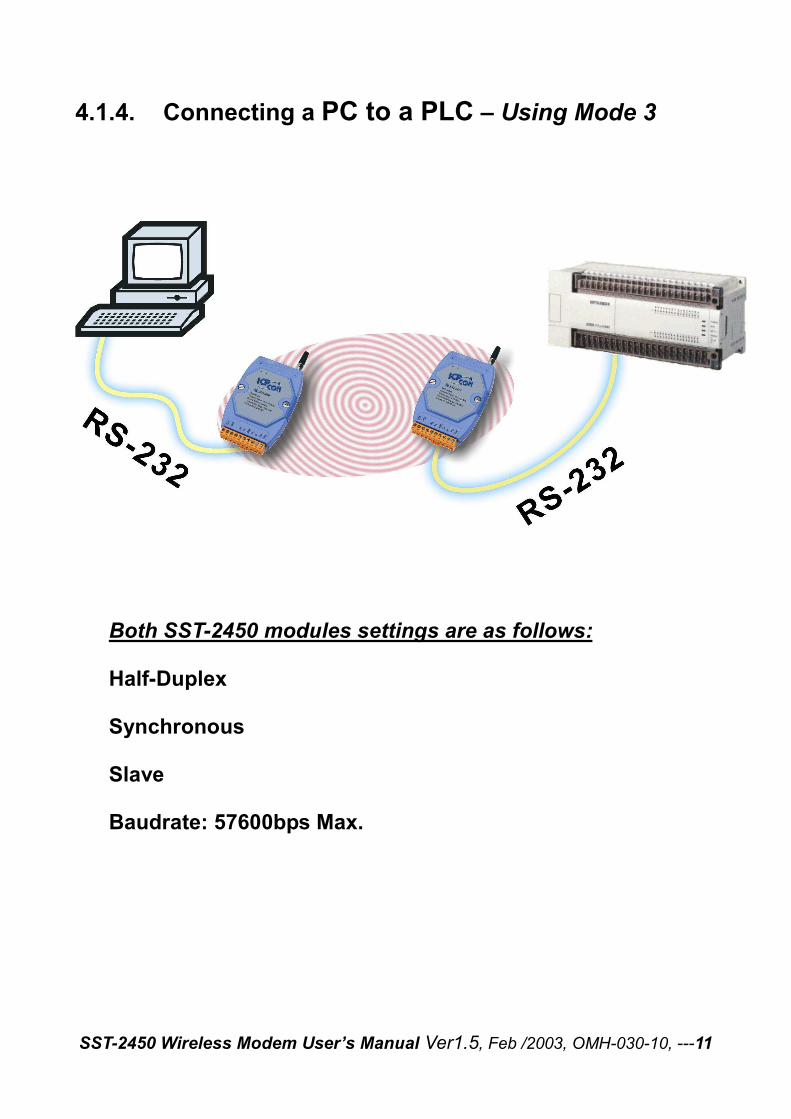
4.1.4. Connecting a PC to a PLC – Using Mode 3
Both SST-2450 modules settings are as follows:
Half-Duplex
Synchronous
Slave
Baudrate: 57600bps Max.
SST-2450 Wireless Modem User’s Manual Ver1.5, Feb /2003, OMH-030-10, ---12
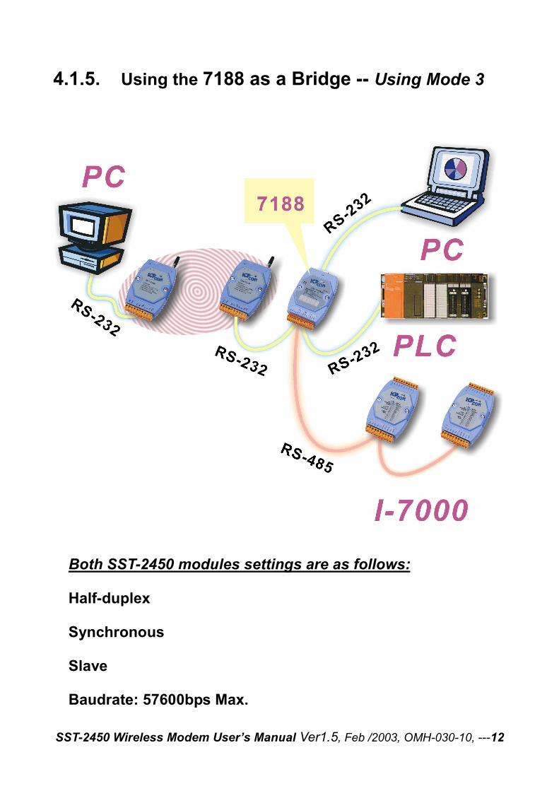
4.1.5. Using the 7188 as a Bridge -- Using Mode 3
Both SST-2450 modules settings are as follows:
Half-duplex
Synchronous
Slave
Baudrate: 57600bps Max.
SST-2450 Wireless Modem User’s Manual Ver1.5, Feb /2003, OMH-030-10, ---13
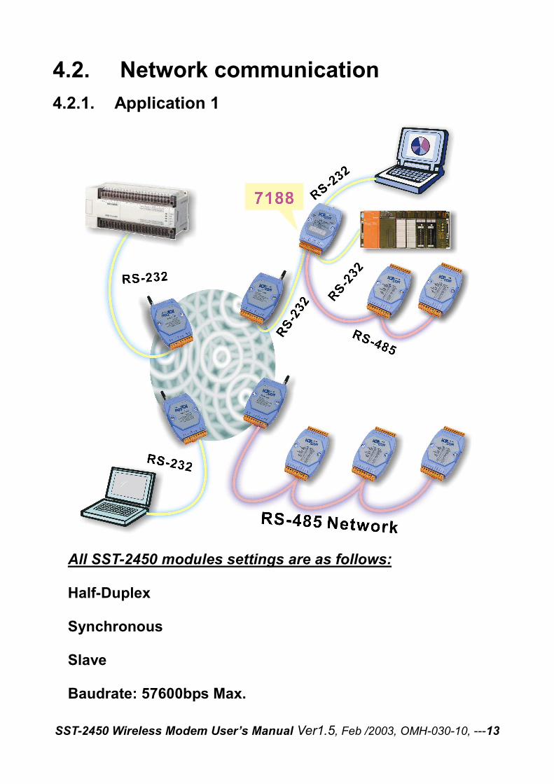
4.2. Network communication 4.2.1. Application 1
All SST-2450 modules settings are as follows:
Half-Duplex
Synchronous
Slave
Baudrate: 57600bps Max.

SST-2450 Wireless Modem User’s Manual Ver1.5, Feb /2003, OMH-030-10, ---14
4.2.2. Application 2
All SST-2450 modules settings are as follows:
Half-duplex
Synchronous
Slave
Baudrate: 57600bps Max.
Data Format: E,8,1
SST-2450 Wireless Modem User’s Manual Ver1.5, Feb /2003, OMH-030-10, ---15
5. Quick Start instructions for the SST-2450
The SST-2450 is set by using a software utility. By using this tool, you are able to avoid disassembling the case. The utility not only provides a setting interface but also a testing interface. When you have finished making the settings, you can simply click a button to test the SST-2450 using the same software.
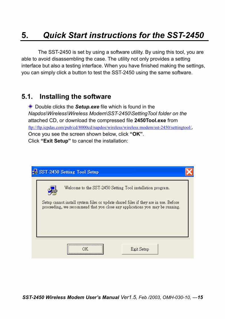
5.1. Installing the software Double clicks the Setup.exe file which is found in the
Napdos\Wireless\Wireless Modem\SST-2450\SettingTool folder on the attached CD, or download the compressed file 2450Tool.exe from ftp://ftp.icpdas.com/pub/cd/8000cd/napdos/wireless/wireless modem/sst-2450/settingtool/, Once you see the screen shown below, click “OK”. Click “Exit Setup” to cancel the installation:
SST-2450 Wireless Modem User’s Manual Ver1.5, Feb /2003, OMH-030-10, ---16
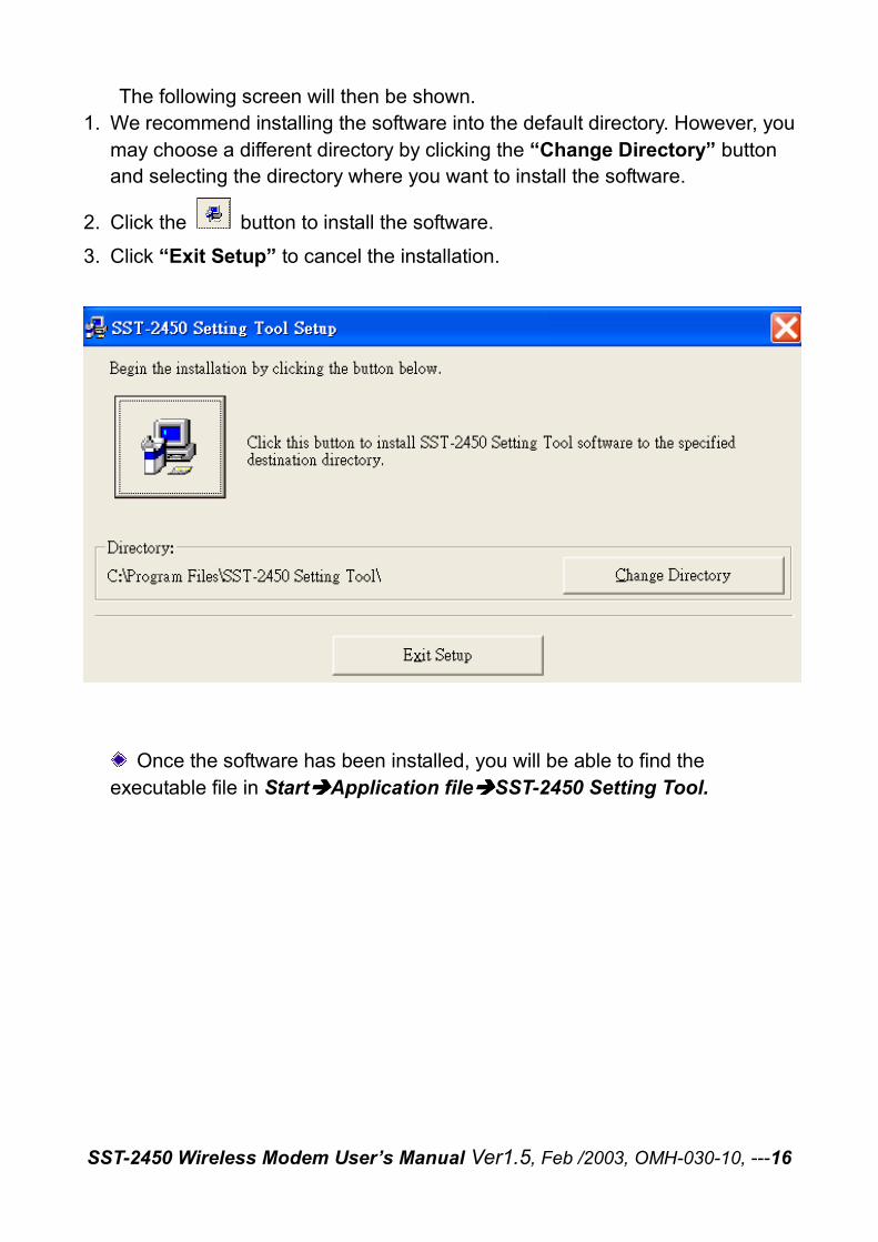
The following screen will then be shown. 1. We recommend installing the software into the default directory. However, you
may choose a different directory by clicking the “Change Directory” button and selecting the directory where you want to install the software.
2. Click the button to install the software.
3. Click “Exit Setup” to cancel the installation.
Once the software has been installed, you will be able to find the executable file in Start����Application file����SST-2450 Setting Tool.
SST-2450 Wireless Modem User’s Manual Ver1.5, Feb /2003, OMH-030-10, ---17
5.2. SST-2450 Settings When setting the SST-2450, you should first use a wire to connect the SET
and GND pins. Quickly power off and power on the SST-2450, then launch the setting software program. There are only 3 steps required to make your settings.
1. Open a Serial Port. 2. Setting the operating mode. 3. Exit the program.
When setting the operating mode, please refer to the following steps:
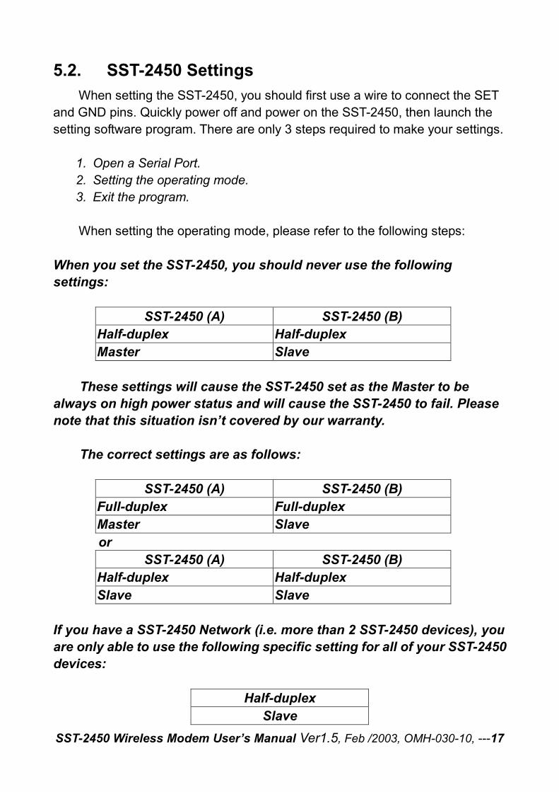
When you set the SST-2450, you should never use the following settings:
SST-2450 (A) SST-2450 (B) Half-duplex Half-duplex Master Slave
These settings will cause the SST-2450 set as the Master to be
always on high power status and will cause the SST-2450 to fail. Please note that this situation isn’t covered by our warranty.
The correct settings are as follows:
SST-2450 (A) SST-2450 (B) Full-duplex Full-duplex Master Slave or
SST-2450 (A) SST-2450 (B) Half-duplex Half-duplex Slave Slave
If you have a SST-2450 Network (i.e. more than 2 SST-2450 devices), you are only able to use the following specific setting for all of your SST-2450 devices:
Half-duplex Slave
SST-2450 Wireless Modem User’s Manual Ver1.5, Feb /2003, OMH-030-10, ---18
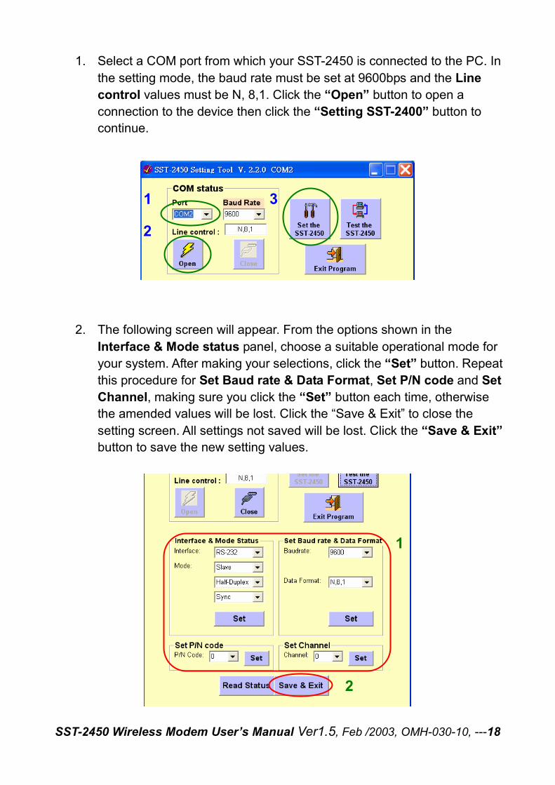
1. Select a COM port from which your SST-2450 is connected to the PC. In the setting mode, the baud rate must be set at 9600bps and the Line control values must be N, 8,1. Click the “Open” button to open a connection to the device then click the “Setting SST-2400” button to continue.
2. The following screen will appear. From the options shown in the
Interface & Mode status panel, choose a suitable operational mode for your system. After making your selections, click the “Set” button. Repeat this procedure for Set Baud rate & Data Format, Set P/N code and Set Channel, making sure you click the “Set” button each time, otherwise the amended values will be lost. Click the “Save & Exit” to close the setting screen. All settings not saved will be lost. Click the “Save & Exit” button to save the new setting values.
1
2
3
1
2
SST-2450 Wireless Modem User’s Manual Ver1.5, Feb /2003, OMH-030-10, ---19
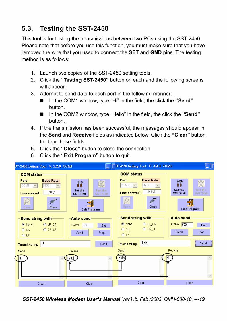
5.3. Testing the SST-2450 This tool is for testing the transmissions between two PCs using the SST-2450. Please note that before you use this function, you must make sure that you have removed the wire that you used to connect the SET and GND pins. The testing method is as follows:
1. Launch two copies of the SST-2450 setting tools, 2. Click the “Testing SST-2450” button on each and the following screens
will appear. 3. Attempt to send data to each port in the following manner:
� In the COM1 window, type “Hi” in the field, the click the “Send” button.
� In the COM2 window, type “Hello” in the field, the click the “Send” button.
4. If the transmission has been successful, the messages should appear in the Send and Receive fields as indicated below. Click the “Clear” button to clear these fields.
5. Click the “Close” button to close the connection. 6. Click the “Exit Program” button to quit.
SST-2450 Wireless Modem User’s Manual Ver1.5, Feb /2003, OMH-030-10, ---20
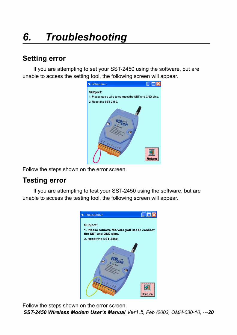
6. Troubleshooting
Setting error
If you are attempting to set your SST-2450 using the software, but are unable to access the setting tool, the following screen will appear.
Follow the steps shown on the error screen.
Testing error
If you are attempting to test your SST-2450 using the software, but are unable to access the testing tool, the following screen will appear.
Follow the steps shown on the error screen.
SST-2450 Wireless Modem User’s Manual Ver1.5, Feb /2003, OMH-030-10, ---21
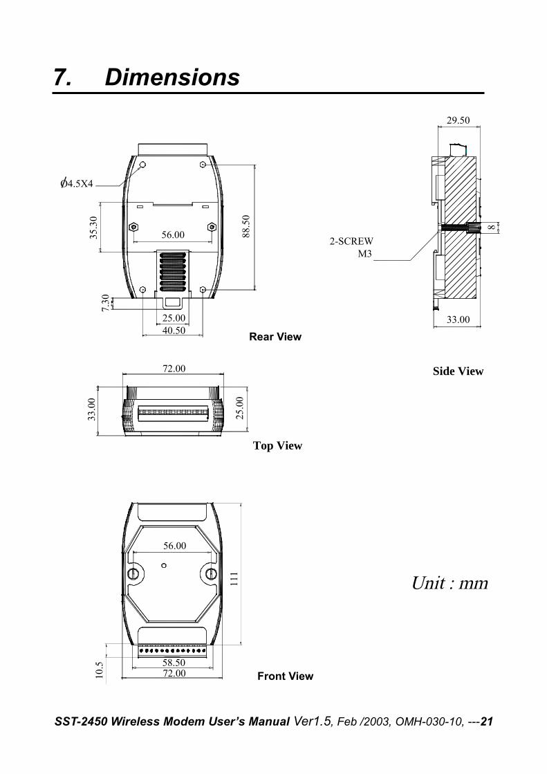
7. Dimensions
111
10.5
Back View
Top View
From View
Side View
O4.5X4
56.00
25.0040.50
7.30
88.5
0
35.3
033
.00
72.00
25.0
0
58.5072.00
56.00
29.50
33.00
2-SCREW M3
8
Front View
Rear View
SST-2450 Wireless Modem User’s Manual Ver1.5, Feb /2003, OMH-030-10, ---22
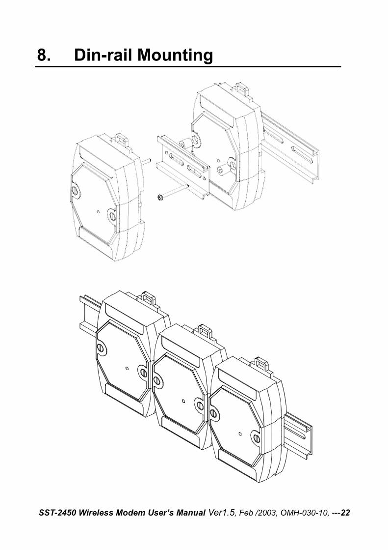
8. Din-rail Mounting
SST-2450 Wireless Modem User’s Manual Ver1.5, Feb /2003, OMH-030-10, ---23
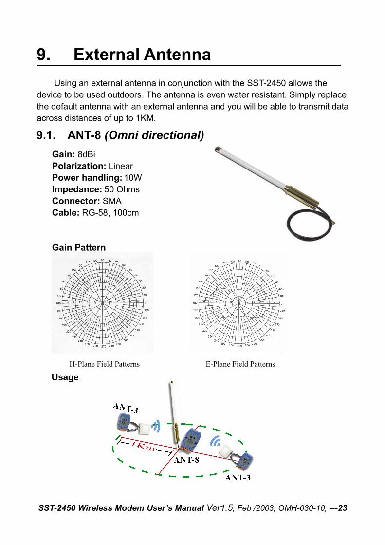
9. External Antenna Using an external antenna in conjunction with the SST-2450 allows the
device to be used outdoors. The antenna is even water resistant. Simply replace the default antenna with an external antenna and you will be able to transmit data across distances of up to 1KM.
SST-2450 Wireless Modem User’s Manual Ver1.5, Feb /2003, OMH-030-10, ---24
9.1. ANT-8 (Omni directional) Gain: 8dBi Polarization: Linear Power handling: 10W Impedance: 50 Ohms Connector: SMA Cable: RG-58, 100cm Gain Pattern
H-Plane Field Patterns E-Plane Field Patterns
Usage
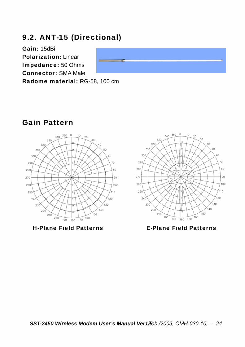
9.2. ANT-15 (Directional) Gain: 15dBi
Feb /2003, OMH-030-10, --- 24
Polarization: Linear
Impedance: 50 Ohms
Connector: SMA Male
Radome material: RG-58, 100 cm
Gain Pattern
H-Plane Field Patterns E-Plane Field Patterns
SST-2450 Wireless Modem User’s Manual Ver1.5,
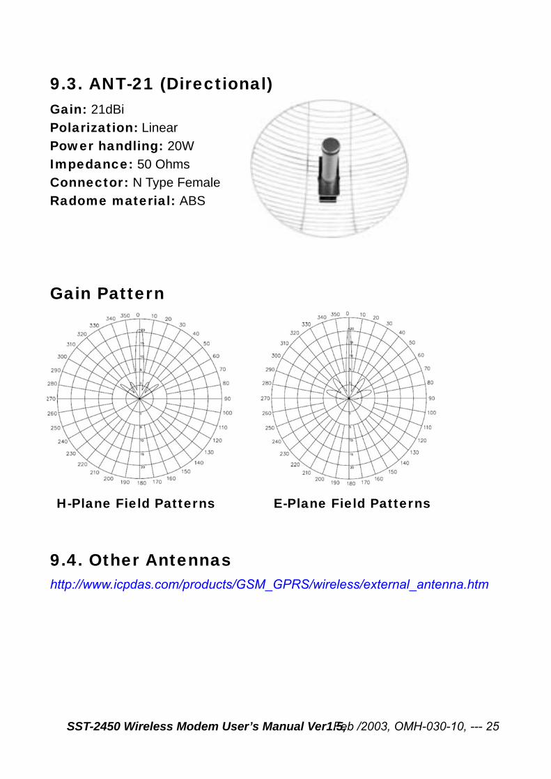
9.3. ANT-21 (Directional) Gain: 21dBi
Feb /2003, OMH-030-10, --- 25
Polarization: Linear
Power handling: 20W
Impedance: 50 Ohms
Connector: N Type Female
Radome material: ABS
Gain Pattern
H-Plane Field Patterns E-Plane Field Patterns
9.4. Other Antennas http://www.icpdas.com/products/GSM_GPRS/wireless/external_antenna.htm
SST-2450 Wireless Modem User’s Manual Ver1.5,
SST-2450 Wireless Modem User’s Manual Ver1.5, Feb /2003, OMH-030-10, ---26
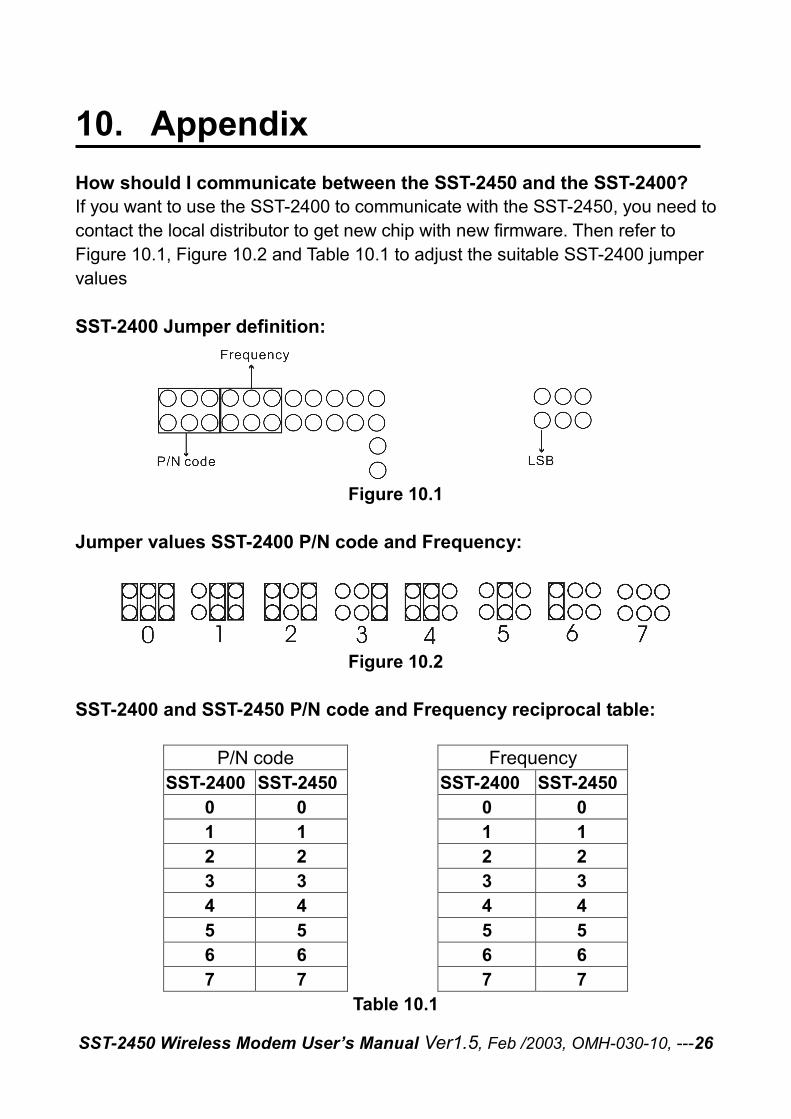
10. Appendix How should I communicate between the SST-2450 and the SST-2400? If you want to use the SST-2400 to communicate with the SST-2450, you need to contact the local distributor to get new chip with new firmware. Then refer to Figure 10.1, Figure 10.2 and Table 10.1 to adjust the suitable SST-2400 jumper values SST-2400 Jumper definition:
Figure 10.1 Jumper values SST-2400 P/N code and Frequency:
Figure 10.2
SST-2400 and SST-2450 P/N code and Frequency reciprocal table: P/N code Frequency SST-2400 SST-2450 SST-2400 SST-2450 0 0 0 0 1 1 1 1 2 2 2 2 3 3 3 3 4 4 4 4 5 5 5 5 6 6 6 6 7 7 7 7
Table 10.1