ssttaattee ooff fflloorriiddaa
TRANSCRIPT

SSTTAATTEE OOFF FFLLOORRIIDDAA
EERROOSSIIOONN AANNDD SSEEDDIIMMEENNTT CCOONNTTRROOLL DESIGNER AND REVIEWER MANUAL
June 2007
Prepared for:
Florida Department of Transportation &
Florida Department of Environmental Protection Tallahassee, FL
Prepared by:
HydroDynamics Incorporated Parker, CO
In cooperation with:
Stormwater Management Academy
University of Central Florida Orlando, FL

STATE OF FLORIDA EROSION & SEDIMENT CONTROL - DESIGNER & REVIEWER MANUAL
Acknowledgments
Development of this manual was funded by the Florida Department of Transportation and the Florida Department of Environmental Protection.
With Special Thanks to the Manual Advisory Committee
Fernando Ascanio, FDOT
Josh Boan, FDOT Manoj Chopra, UCF
Susan Davis, SJRWMD Cammie Dewey, SJRWMD
Jerry Fifield, HDI Carol Griggs, SJRWMD
Steve Iwinski, APS Eric Livingston, FDEP Paul O’Neil, SWFWMD
Rick Renna, FDOT Andi Reyes, SFWMD
Heather Ritchie, FDEP Larry Ritchie, FDOT David Sadler, FDOT
Jenny Sargent, FDOT Jim Smoot, USGS
Marty Wanielista, UCF Ben Watson, FDOT Molly Wood, USGS Ed Yaun, SFWMD
This manual was edited by Ryan Browne, UCF and approved for publication.
© June 2007

STATE OF FLORIDA EROSION & SEDIMENT CONTROL - DESIGNER & REVIEWER MANUAL
INTRODUCTION
With the adoption of the statewide stormwater rule in 1982, Florida was the first state in the
country to require the treatment of stormwater from all new development. The stormwater rule
is a technology-based rule relying upon a performance standard (environmental goal) and Best
Management Practices (BMPs) design criteria that are presumed to meet the goal. The
performance standards are set forth in the Water Resource Implementation Rule (Chapter 62-40,
F.A.C.).
Performance standards for erosion and sediment control during grading is to retain sediment on-
site, with a backstop that no discharge shall violate the State of Florida‟s water quality standard
for turbidity. Thus, goals of Florida‟s stormwater regulatory program and the Florida
Department of Environmental Protection (FDEP) are to protect water quality and to minimize
erosion and sedimentation by requiring the use of effective BMPs during and after grading.
Additionally, as mandated by the Clean Water Act (CWA), permits must be obtained for
stormwater discharges from construction sites that meet or exceed the Environmental Protection
Agency (EPA)‟s criteria (see http://www.epa.gov/region5/water/cwa.htm). The EPA has the
responsibility of administering CWA requirements by requiring National Pollutant Discharge
Elimination System (NPDES) discharge permits.
FDEP implements the NPDES program in Florida and issues Florida NPDES discharge permits.
By reviewing http://www.dep.state.fl.us/water/stormwater/npdes/index.htm, readers of this
manual can obtain more detailed information on Florida statutory requirements and FDEP
programs and requirements.
Purpose of the Manual
This manual will assist designers and reviewers in providing meaningful and practical Erosion
and Sediment Control (E&SC) drawings as part of the Stormwater Pollution Prevention Plan
(SWPPP) for the contractor to implement. Preparation and review of SWPPP and E&SC
drawings need to be done by, or under the supervision of, professionals having demonstrative
erosion and sediment control experience and skills necessary for development and review of
effective and practical documents. These individuals are identified throughout this manual as
Designers. It is important to note that additional qualifications may be required by governmental
agencies, such as having construction field experience, supplementary training and education,
passing an examination, and so forth.
This manual has been developed to strive toward a consistent level of technical expertise and
professional conduct for designers and reviewers developing and reviewing E&SC drawings and
SWPPP. These are required not only to meet NPDES stormwater requirements but are also an
integral part of the stormwater management plan that must be approved by FDEP or the Water
Management Districts (WMDs) to obtain a Florida stormwater or Environmental Resource
Permit (ERP). Ultimately, the guidance in this manual strives to ensure the desired benefits of
stormwater management systems are being achieved.
I-1

STATE OF FLORIDA EROSION & SEDIMENT CONTROL - DESIGNER & REVIEWER MANUAL
Three Basic Definitions
Natural erosion occurs at a relatively slow rate; however, accelerated erosion is primarily caused
by the removal of natural vegetation or alteration of the ground contour by land disturbing and
construction activities. The nature of construction activities will result in increased erosion rates,
transportation of sediment by runoff, and create problems associated with sedimentation. The
purpose of this manual is to present methods that Designers can use and reviewers will recognize
to reduce sediment in runoff waters and minimize the erosion process on sites where construction
activity is occurring. It is important that Designers and reviewers understand the following three
basic definitions:
Erosion: The process by which rainfall, wind and water dislodges soil particles.
Splash erosion is the dislodging of soil particles by raindrop impacts, resulting in the
dispersal and mobilization of the soil particles.
Sheet flow erosion is the uniform removal of saturated soil particles conveyed in runoff
waters.
Rill erosion is a long, narrow depression or soil incision caused by increased topographic
relief and higher runoff velocities. They are the result of concentrated flows that result in
vertical (meaning, incising into the ground) and sheet flow erosion.
Gully erosion is the deep and wide depression caused by concentrated flows.
Stream bank erosion is the removal of soil by a natural drainage pattern, such as toe
cutting and bank sloughing.
Shoreline erosion is the removal of soil by high-energy wave action, resulting in
sloughing and mass wasting.
Sediment: Soil particles suspended in, or moved by, stormwater runoff.
Sedimentation: The deposition of sediment.
Some of the factors influencing erosion include soil characteristics, existing vegetative cover,
topography and climate. Soil properties which influence erosion by rainfall and stormwater
runoff are those which affect the infiltration capacity of a soil and those which affect the
resistance of the soil to detachment and transport by flowing or falling water. Vegetative cover
plays an extremely important role in reducing erosion and can be controlled during land
disturbing activities.
Sequentially scheduling and limiting the removal of vegetation and decreasing the area and
duration of exposure can significantly reduce soil erosion and sedimentation. Topographic
characteristics of the watershed can influence the amount and rate of stormwater runoff since
slope length and gradient directly influence the volume and velocity of runoff and erosion risks.
Climate, especially rainfall frequency, intensity and duration are fundamental factors in
determining the amount of runoff. As volume and velocity increase, the capacity of runoff to
detach and transport soil particles also increases.
This manual will provide guidelines for developing and reviewing effective E&SC drawings that
incorporate methods for removing sediment from runoff waters and minimize erosion in a cost
effective and practical manner that protects the environment while construction activities occur.
I-2

STATE OF FLORIDA EROSION & SEDIMENT CONTROL - DESIGNER & REVIEWER MANUAL
SECTION II
DEVELOPING EFFECTIVE SWPPP’S AND E&SC DRAWINGS
STATE OF FLORIDA EROSION & SEDIMENT CONTROL - DESIGNER & REVIEWER MANUAL
Table of Contents
CONTENTS OF A SWPPP ............................................................................................. 1
NARRATIVE REPORT ....................................................................................................... 1 Designer Certification Requirement .....................................................................................2
Contractor Certification Requirement ...................................................................................2
CALCULATIONS .............................................................................................................. 3 EROSION AND SEDIMENT CONTROL DRAWINGS ................................................................ 3 RECORD REQUIREMENTS ................................................................................................ 5
SWPPP and E&SC Drawing Update Requirements ............................................................6
DEVELOPING EFFECTIVE E&SC DRAWINGS ............................................................ 6
THE IMPORTANCE OF PERTINENT DATA ............................................................................ 7 Collecting Data ....................................................................................................................7
Interpreting and Evaluating Data .........................................................................................7
DEVELOPING EFFECTIVE E&SC DRAWINGS ..................................................................... 8 Title Sheet ...........................................................................................................................8
Pre Grading Drawings .........................................................................................................8
During Grading Drawings ....................................................................................................9
After Grading Drawings .....................................................................................................10
Typical Detail and Specification Sheets .............................................................................11
Miscellaneous Comments .................................................................................................12
E&SC Drawing Summary ..................................................................................................12

STATE OF FLORIDA EROSION & SEDIMENT CONTROL - DESIGNER & REVIEWER MANUAL
II-1
CONTENTS OF A SWPPP
The Stormwater Pollution Prevention Plan and accompanying E&SC plans shall identify
potential sources of pollution that may reasonably be expected to affect the quality of stormwater
discharge associated with construction activity. In addition, the plan shall describe and ensure
the implementation of BMPs, which will be used to reduce the pollutants in stormwater
discharge associated with construction activity and to assure compliance with the terms and
conditions of the permit. A thorough understanding of the plan is essential for proper
implementation and maintenance.
The SWPPP must be developed before an NOI is filed to receive the Generic Permit for
Stormwater Discharge from Large and Small Construction Activities (CGP) coverage and meet
or exceed FDEP requirements. Also, beginning on the first day of construction activities, the
SWPPP and E&SC drawings must be available at the location identified in the NOI (see
http://www.dep.state.fl.us). A copy of the NOI or Notice of Coverage from FDEP shall be
posted at the construction site in a prominent place for viewing. The location of the SWPPP is
identified in the NOI and may or may not necessarily be at the construction site.
A SWPPP will consist of a narrative (including any calculations), E&SC drawings, and record
requirements. In addition, the CGP requires a certification statement to be signed by the
operator. It is strongly recommended that the Designer also sign a certification to ensure
accountability exists. The SWPPP shall be developed and implemented for each construction
site covered by this permit and be prepared in accordance with good engineering and scientific
practices.
Narrative Report
The narrative report provides general information on what is to be completed to ensure minimal
environmental damage as a construction project is developed. It should briefly describe the
overall strategy for erosion and sediment control, as well as summarize the aspects of the project
that are important for erosion control on-site for the plan reviewer and project superintendent.
A site description shall be included in the narrative report and include at a minimum the
following information about the site:
Description of the construction activity
Total area of the site and total disturbance area
Intended sequence of land disturbing activities
Description of the soils and an identification of those that are highly erodible
Drainage area for each major discharge point
Latitude and longitude of each major discharge point
Names of receiving water(s)
Description of proposed pollution control measures (i.e. BMPs) to be used
General sequence during the construction process in which the measures will be installed
Estimated start date, completion date and stabilization schedule
If possible, an identification of the contractor or subcontractor responsible for the BMP
implementation, inspection, and maintenance

STATE OF FLORIDA EROSION & SEDIMENT CONTROL - DESIGNER & REVIEWER MANUAL
III-9
Figure III-2: Illustration of Installing a RECP on a Disturbed Slope Permission is given by HydroDynamics Incorporated to copy and reproduce this detail

STATE OF FLORIDA EROSION & SEDIMENT CONTROL - DESIGNER & REVIEWER MANUAL
III-12
Table III-1: Manning’s Roughness Coefficients for Various Materials (Fifield, 2004)
Material
Depth of
0 to 6 in.
Depth of
6 in. to 24 in.
Depth
>24 in.
Bare soila 0.023 0.020 0.020
Rock cuta 0.045 0.035 0.025
Gravel riprapa
D50 = 1.0 inches 0.044 0.033 0.030
D50 = 2.0 inches 0.066 0.041 0.034
Rock riprapa
D50 = 6.0 inches 0.104 0.069 0.035
D50 = 12 inches ---- 0.078 0.040
Concretea 0.015 0.013 0.013
Grouted riprapa 0.040 0.030 0.028
Stone masonrya 0.042 0.032 0.030
Soil cementa 0.025 0.022 0.020
Asphalta 0.018 0.016 0.016
Fiberglass rovinga 0.028 0.021 0.019
Straw (loose) covered with neta 0.065 0.033 0.025
EROSION CONTROL BLANKET
Jute neta 0.028 0.022 0.019
Wood excelsior mata 0.066 0.035 0.028
TURF REINFORCEMENT MAT
Bare ground conditionsb 0.036 0.026 0.020
Vegetation conditionsb 0.023 0.020 0.020
a Chen and Cotton (1988)
b IECA (1995)
STATE OF FLORIDA EROSION & SEDIMENT CONTROL - DESIGNER & REVIEWER MANUAL
III-13
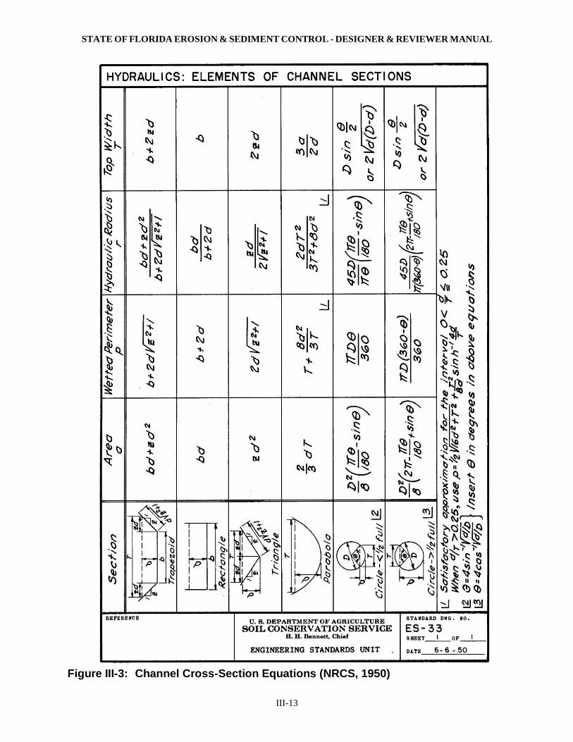
Figure III-3: Channel Cross-Section Equations (NRCS, 1950)

STATE OF FLORIDA EROSION & SEDIMENT CONTROL - DESIGNER & REVIEWER MANUAL
III-14
Table III-2: Permissible Shear-Stress Values and Velocities for Various Materials (Fifield, 2004)
Material
Test
Time
(hr.)
Maximum
Shear Stress
(lbs./ft.2)
Maximum
Velocity
(ft./sec.)
Bare soila
Non-cohesive (Diameter = 0.004 to 4.0 in.) NDG 0.004 to 1.67 NDG
Cohesive Loose (Plasticity Index = 3.0 to 50) NDG 0.01 to 0.090 NDG
Cohesive Medium Compact (Plasticity Index = 3.0 to 50) NDG 0.015 to 0.27 NDG
Cohesive Compact (Plasticity Index = 3.0 to 50) NDG 0.022 to 0.79 NDG
Gravel riprapa
D50 = 1.0 inches NDG 0.31 NDG
D50 = 2.0 inches NDG 0.67 NDG
Rock riprapa
D50 = 6.0 inches NDG 1.99 NDG
D50 = 12 inches NDG 3.99 NDG
Grass (established)a
Height Classification Examples
A (30 in.) Weeping lovegrass and Yellow bluestem NDG 3.76 NDG
B (12 to 24 in.) bermuda grass, Little bluestem, Bluestem, Blue
gamma, and other long and short Midwest grasses NDG 2.09 NDG
C (6 to 12 in.) Crabgrass, bermuda grass, orchard grass, redtop,
Italian ryegrass, Kentucky bluegrass, common
lespedeza NDG 1.05 NDG
D (2 to 6 in.) bermuda grass, buffalo grass, orchard grass,
redtop, Italian ryegrass, common lespedeza NDG 0.63 NDG
E (1.6 in.) bermuda grass NDG 0.31 NDG
Fiberglass Rovinga
Single NDG 0.61 NDG
Double NDG 0.86 NDG
Straw (loose) covered with neta NDG 1.44 NDG
EROSION CONTROL BLANKET
Coconut materialc 0.5 2.26 9.8
Wood excelsior materiala,b,c NDG 0.50 to 2.00 4.9 to 7.9
Jute neta NDG 0.45 NDG
Straw blanket with sewn netb,c 0.50 1.50 to 1.75 4.9 to 5.9
Straw/coconut blanket with sewn netb,c 0.5 2.00 to 2.10 7.9
TURF REINFORCEMENT MAT
Bare Ground Conditionsa,b,c 0.50 3.00 to 8.00 8.9 to 20.0
50 2.00 to 3.00 7.9 to 14.1
Vegetation Establishedb,c 0.50 6.00 to 14.0 14.8 to 25.0
50 6.00 to 12.0 9.8 to 14.1
a Chen and Cotton (1988) c As reported by the manufacturer
b IECA (1991, 1992, 1995) NDG = No data given