st 3000 smart transmitter series 900 remote diaphragm ... · pdf filest 3000 smart transmitter...
TRANSCRIPT
ST 3000 Smart TransmitterSeries 900 Remote Diaphragm Seals Models Specifications 34-ST-03-57 March 2013
Introduction
In 1983, Honeywell introduced the first Smart Pressure
Transmitter― the ST 3000®. In 1989, Honeywell launched
the first all digital, bi-directional protocol for smart field
devices. Today, its ST 3000 Series 900 Remote Seal
Transmitters continue to bring proven “smart” technology to
a wide spectrum of pressure measurement applications.
For applications in which the transmitter must be mounted
remotely from the process, Honeywell offers the remote
seal line of gauge, absolute and differential pressure
transmitters. Typical applications include level
measurement in pressurized vessels in the chemical and
hydrocarbon processing industries. A second application is
flow measurement for slurries and high viscosity fluids in
the chemical industry. Honeywell remote seal transmitters
are available with secondary fill fluids for corrosive or high
temperature process fluids.
Models
STR93D 0 to 100 psid 0 to 7 bar
STR94G 0 to 500 psig 0 to 35 bar
All ST 3000 transmitters can be ordered to provide one of
the following output communication options.
Communications options
4-20 mA
Honeywell Digitally Enhanced (DE)
HART® (versions 5.x or 6.x)
FOUNDATION™ Fieldbus
The devices provide comprehensive self-diagnostics to help users maintain high uptime, meet regulatory requirements, and attain high quality standards. S900 transmitters allow smart performance at analog prices. Accurate, reliable and stable, Series 900 transmitters offer greater turndown ratio than conventional transmitters.
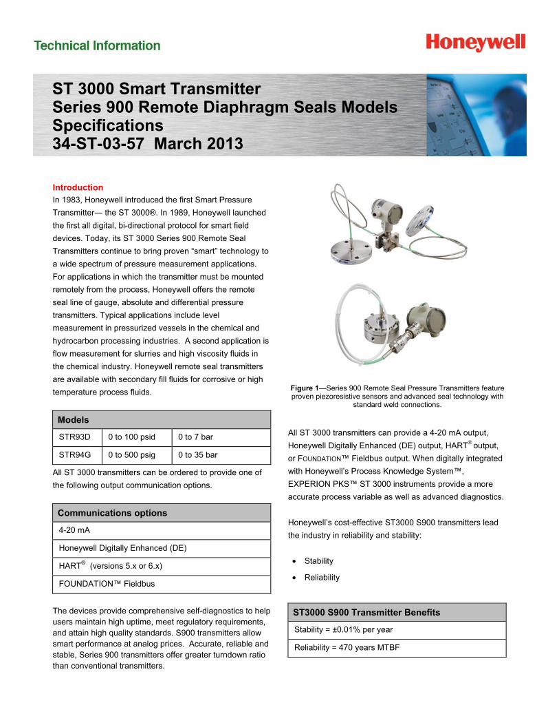
Figure 1—Series 900 Remote Seal Pressure Transmitters feature proven piezoresistive sensors and advanced seal technology with
standard weld connections.
All ST 3000 transmitters can provide a 4-20 mA output,
Honeywell Digitally Enhanced (DE) output, HART® output,
or FOUNDATION™ Fieldbus output. When digitally integrated
with Honeywell’s Process Knowledge System™,
EXPERION PKS™ ST 3000 instruments provide a more
accurate process variable as well as advanced diagnostics.
Honeywell’s cost-effective ST3000 S900 transmitters lead
the industry in reliability and stability:
• Stability
• Reliability
ST3000 S900 Transmitter Benefits
Stability = ±0.01% per year
Reliability = 470 years MTBF
2 ST 3000 Smart Pressure Transmitter
Description of Diaphragm Seals
Diaphragm seals are traditionally used when a standard
pressure transmitter should not be exposed to the process
pressure directly. Diaphragm seals typically protect the
pressure transmitter from one or more damaging aspects of
the process media. Consideration for using a diaphragm
seal should be made in the following circumstances.
• High Process Temperature
• Process Media is Viscous or Contains Suspended
Solids
• Process Media is Subject to Solidifying
• Process Media is Corrosive
• Process Application Requires Sanitary Connections
• Process Application Subjects the Measuring Instrument
to Hydrogen Permeation
• Tank Level Applications with Maintenance Intensive
Wet Legs
• Tank Application with Density or Interface
Measurements
• Measuring Instrument Requires Remote Mounting
The following diaphragm seals are standard from
Honeywell (please call your local salesperson if you do not
see the product you need for your application)
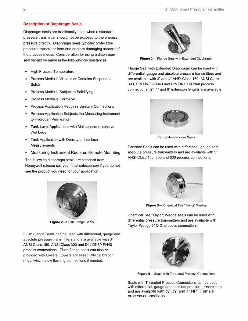
Figure 2—Flush Flange Seals
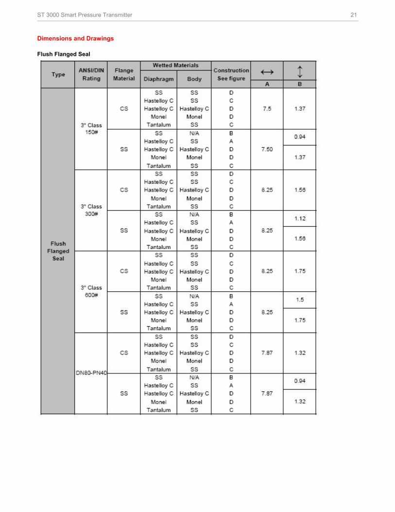
Flush Flange Seals can be used with differential, gauge and
absolute pressure transmitters and are available with 3”
ANSI Class 150, ANSI Class 300 and DIN DN80-PN40
process connections. Flush flange seals can also be
provided with Lowers. Lowers are essentially calibration
rings, which allow flushing connections if needed.
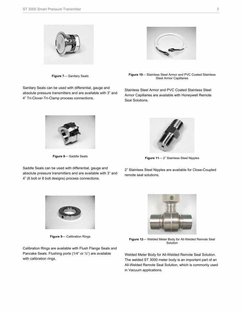
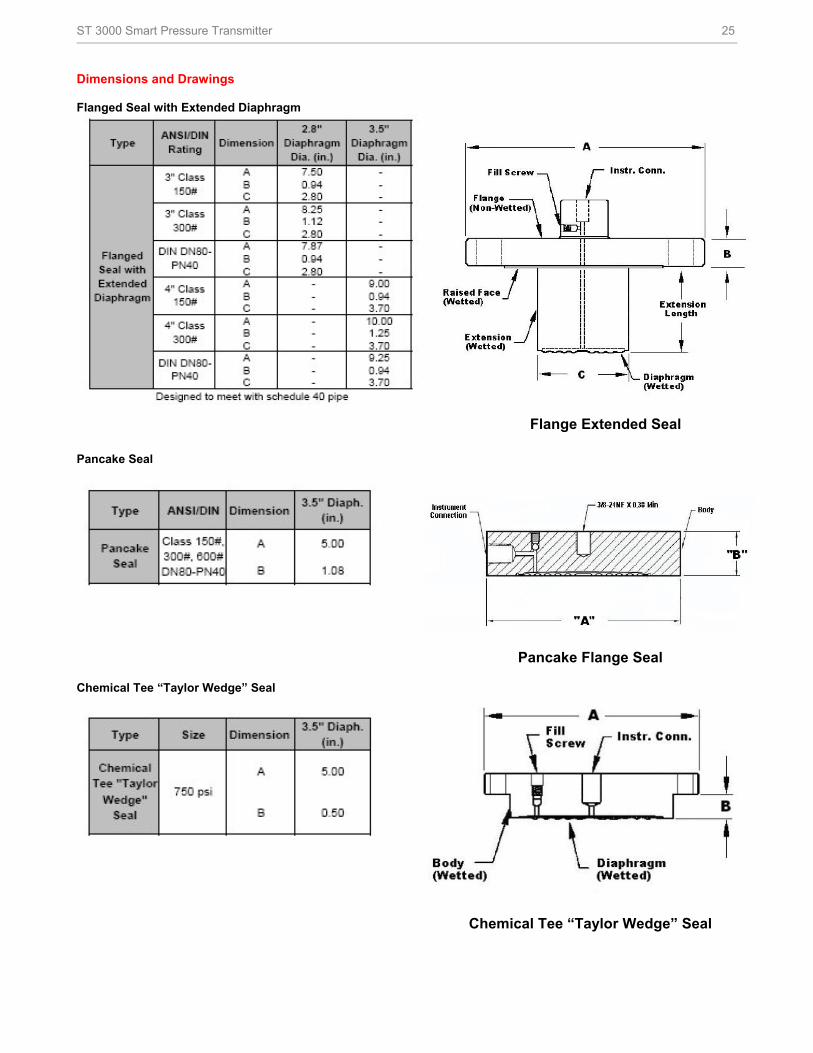
Figure 3— Flange Seal with Extended Diaphragm
Flange Seal with Extended Diaphragm can be used with
differential, gauge and absolute pressure transmitters and
are available with 3” and 4” ANSI Class 150, ANSI Class
300, DIN DN80-PN40 and DIN DN100-PN40 process
connections. 2”, 4” and 6” extension lengths are available.
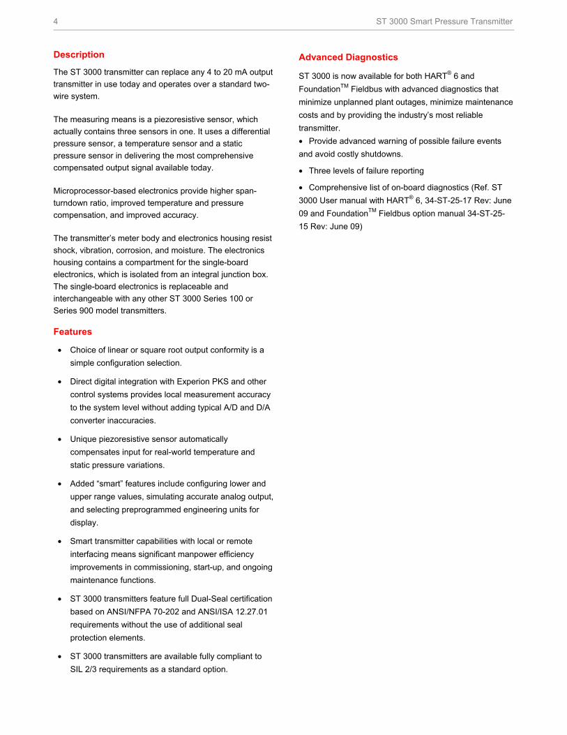
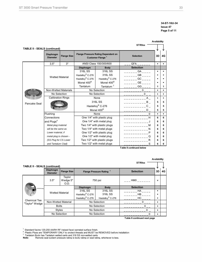
Figure 4—Pancake Seals
Pancake Seals can be used with differential, gauge and
absolute pressure transmitters and are available with 3”
ANSI Class 150, 300 and 600 process connections.
Figure 5— Chemical Tee “Taylor” Wedge
Chemical Tee “Taylor” Wedge seals can be used with
differential pressure transmitters and are available with
Taylor Wedge 5” O.D. process connection.
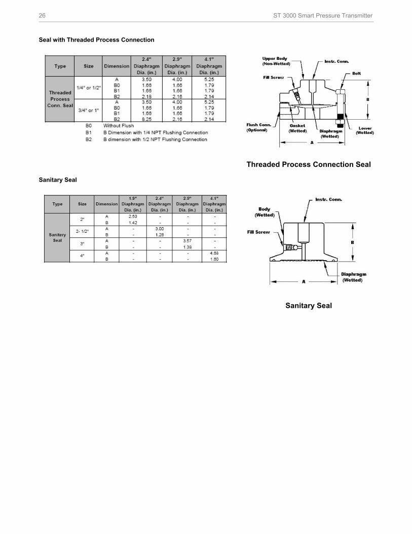
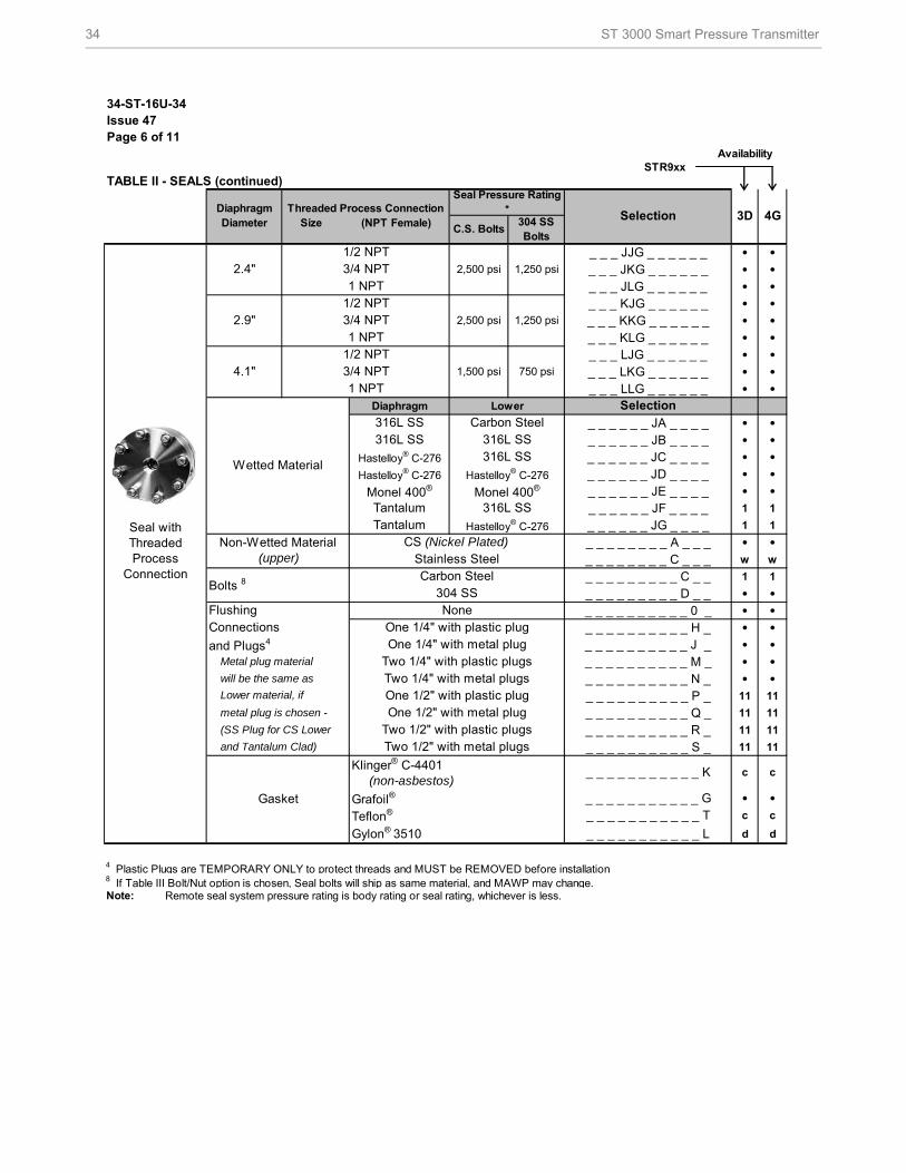
Figure 6— Seals with Threaded Process Connections
Seals with Threaded Process Connections can be used with differential, gauge and absolute pressure transmitters and are available with ½”, ¾” and 1” NPT Female process connections.
ST 3000 Smart Pressure Transmitter 3
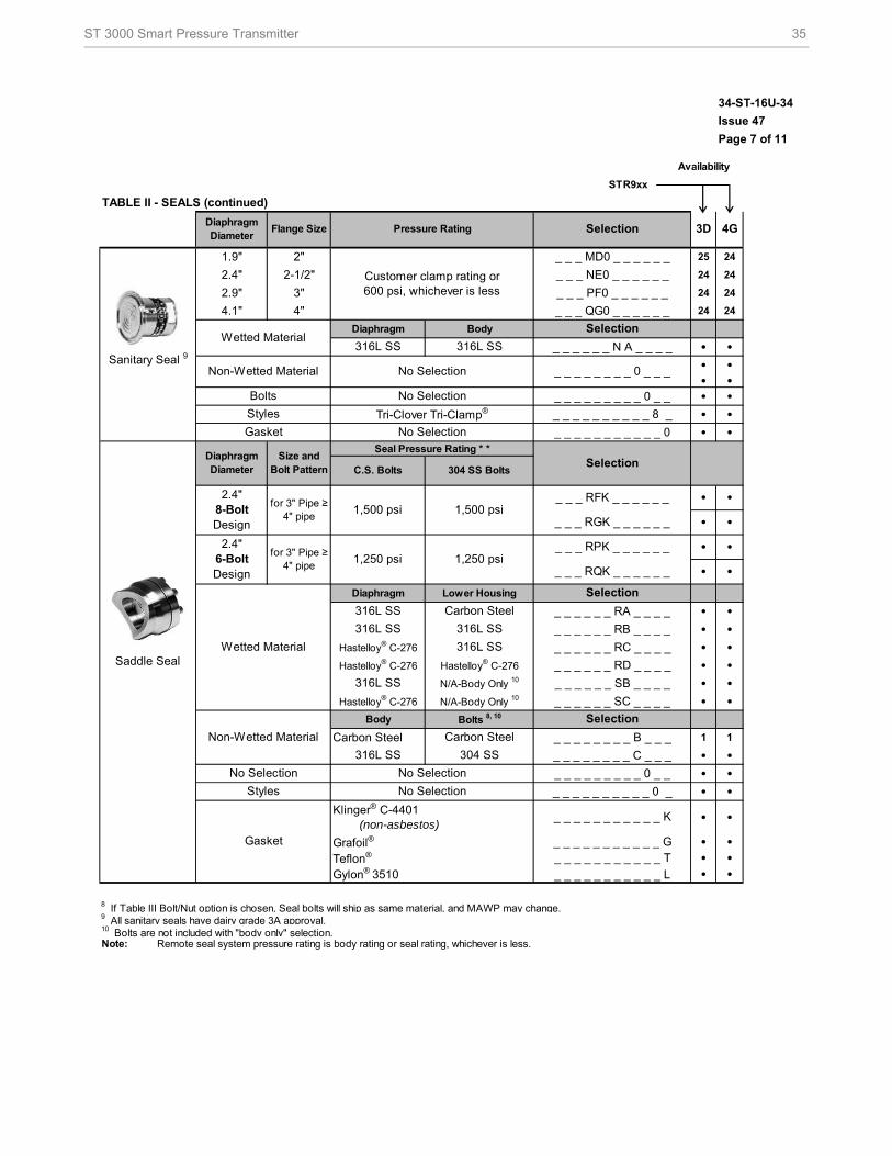
Figure 7— Sanitary Seals
Sanitary Seals can be used with differential, gauge and
absolute pressure transmitters and are available with 3” and
4” Tri-Clover-Tri-Clamp process connections.
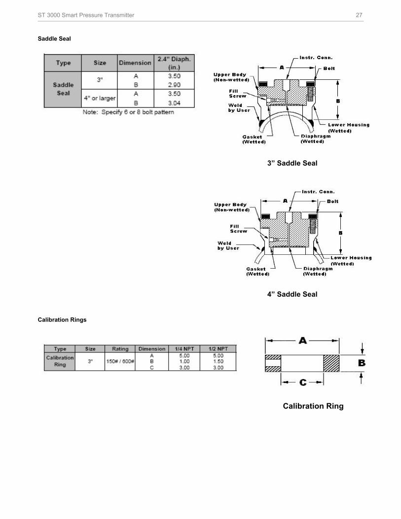
Figure 8— Saddle Seals
Saddle Seals can be used with differential, gauge and
absolute pressure transmitters and are available with 3” and
4” (6 bolt or 8 bolt designs) process connections.
Figure 9— Calibration Rings
Calibration Rings are available with Flush Flange Seals and
Pancake Seals. Flushing ports (1/4” or ½”) are available
with calibration rings.
Figure 10— Stainless Steel Armor and PVC Coated Stainless Steel Armor Capillaries
Stainless Steel Armor and PVC Coated Stainless Steel
Armor Capillaries are available with Honeywell Remote
Seal Solutions.
Figure 11— 2” Stainless Steel Nipples
2” Stainless Steel Nipples are available for Close-Coupled
remote seal solutions.
Figure 12— Welded Meter Body for All-Welded Remote Seal Solution
Welded Meter Body for All-Welded Remote Seal Solution.
The welded ST 3000 meter body is an important part of an
All-Welded Remote Seal Solution, which is commonly used
in Vacuum applications.
4 ST 3000 Smart Pressure Transmitter
Description
The ST 3000 transmitter can replace any 4 to 20 mA output
transmitter in use today and operates over a standard two-
wire system.
The measuring means is a piezoresistive sensor, which
actually contains three sensors in one. It uses a differential
pressure sensor, a temperature sensor and a static
pressure sensor in delivering the most comprehensive
compensated output signal available today.
Microprocessor-based electronics provide higher span-
turndown ratio, improved temperature and pressure
compensation, and improved accuracy.
The transmitter’s meter body and electronics housing resist
shock, vibration, corrosion, and moisture. The electronics
housing contains a compartment for the single-board
electronics, which is isolated from an integral junction box.
The single-board electronics is replaceable and
interchangeable with any other ST 3000 Series 100 or
Series 900 model transmitters.
Features
• Choice of linear or square root output conformity is a
simple configuration selection.
• Direct digital integration with Experion PKS and other
control systems provides local measurement accuracy
to the system level without adding typical A/D and D/A
converter inaccuracies.
• Unique piezoresistive sensor automatically
compensates input for real-world temperature and
static pressure variations.
• Added “smart” features include configuring lower and
upper range values, simulating accurate analog output,
and selecting preprogrammed engineering units for
display.
• Smart transmitter capabilities with local or remote
interfacing means significant manpower efficiency
improvements in commissioning, start-up, and ongoing
maintenance functions.
• ST 3000 transmitters feature full Dual-Seal certification
based on ANSI/NFPA 70-202 and ANSI/ISA 12.27.01
requirements without the use of additional seal
protection elements.
• ST 3000 transmitters are available fully compliant to
SIL 2/3 requirements as a standard option.
Advanced Diagnostics
ST 3000 is now available for both HART® 6 and
FoundationTM Fieldbus with advanced diagnostics that
minimize unplanned plant outages, minimize maintenance
costs and by providing the industry’s most reliable
transmitter.
• Provide advanced warning of possible failure events
and avoid costly shutdowns.
• Three levels of failure reporting
• Comprehensive list of on-board diagnostics (Ref. ST
3000 User manual with HART® 6, 34-ST-25-17 Rev: June
09 and FoundationTM Fieldbus option manual 34-ST-25-
15 Rev: June 09)
ST 3000 Smart Pressure Transmitter 5
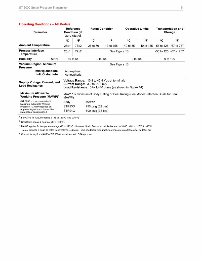
Operating Conditions – All Models
Parameter Reference
Condition (at zero static)
Rated Condition Operative Limits Transportation and Storage
°C °F °C °F °C °F °C °F
Ambient Temperature 25±1 77±2 -25 to 70 -13 to 158 -40 to 85 -40 to 185 -55 to 125 -67 to 257
Process Interface Temperature
25±1 77±2 See Figure 13 -55 to 125 -67 to 257
Humidity %RH 10 to 55 0 to 100 0 to 100 0 to 100
Vacuum Region, Minimum Pressure mmHg absolute inH2O absolute
AtmosphericAtmospheric
See Figure 13
Supply Voltage, Current, and Load Resistance
Voltage Range: 10.8 to 42.4 Vdc at terminals Current Range: 3.0 to 21.8 mA Load Resistance: 0 to 1,440 ohms (as shown in Figure 14)
Maximum Allowable Working Pressure (MAWP)4
(ST 3000 products are rated to Maximum Allowable Working Pressure. MAWP depends on Approval Agency and transmitter materials of construction.)
MAWP is minimum of Body Rating or Seal Rating (See Model Selection Guide for Seal MAWP)
Body MAWP
STR93D 750 psig (52 bar)
STR94G 500 psig (35 bar)
1 For CTFE fill fluid, the rating is -15 to 110°C (5 to 230°F) 2 Short term equals 2 hours at 70°C (158°F) 3 MAWP applies for temperature range -40 to 125°C. However, Static Pressure Limit is de-rated to 3,000 psi from -26°C to -40°C.
Use of graphite o-rings de-rates transmitter to 3,625 psi. Use of adaptor with graphite o-rings de-rates transmitter to 3,000 psi. 4 Consult factory for MAWP of ST 3000 transmitters with CSA approval.
6 ST 3000 Smart Pressure Transmitter
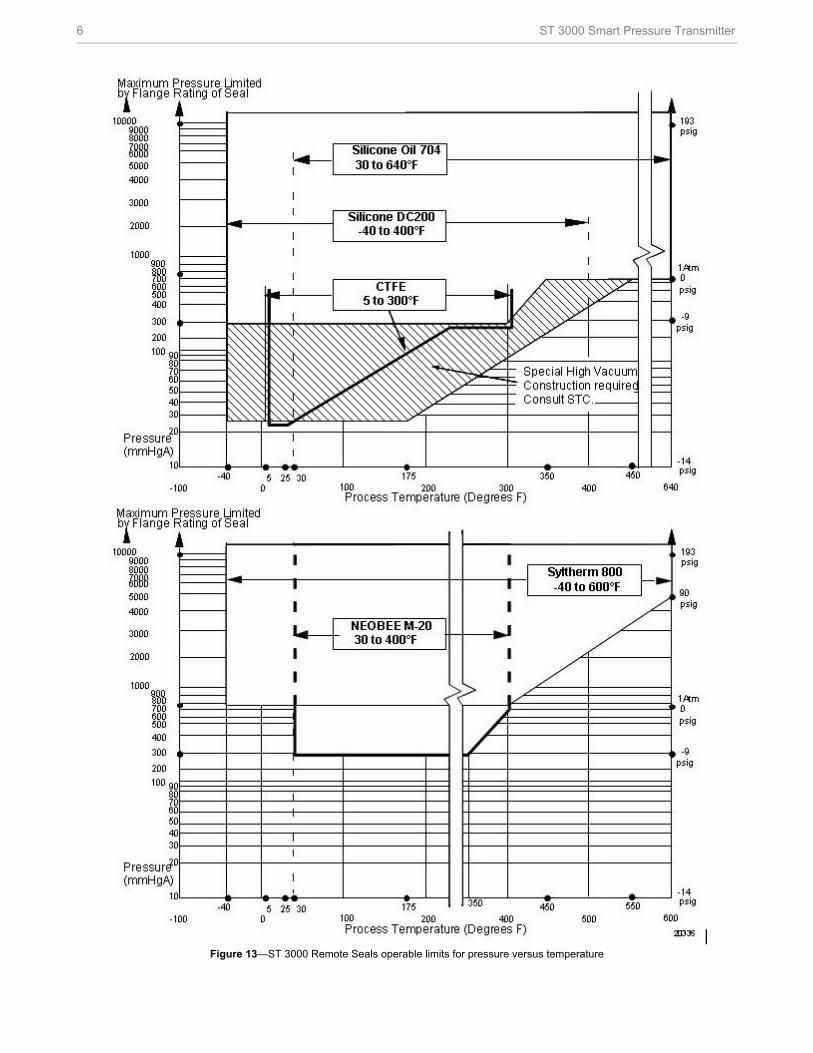
Figure 13—ST 3000 Remote Seals operable limits for pressure versus temperature
ST 3000 Smart Pressure Transmitter 7
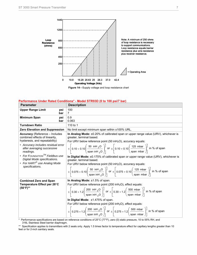
Note: A minimum of 250 ohms of loop resistance is necessary to support communications. Loop resistance equals barrier resistance plus wire resistance plus receiver resistance.
= Operating Area
0 10.8 16.28 20.63 25 28.3 37.0 42.4
1440
1200
800
650
450
250
Operating Voltage (Vdc)
LoopResistance
(ohms)
Figure 14—Supply voltage and loop resistance chart
Performance Under Rated Conditions* - Model STR93D (0 to 100 psi/7 bar) Parameter Description
Upper Range Limit psi bar
100 7
Minimum Span psi bar
0.9 0.063
Turndown Ratio 110 to 1
Zero Elevation and Suppression No limit except minimum span within ±100% URL.
Accuracy (Reference – Includes combined effects of linearity, hysteresis, and repeatability)
• Accuracy includes residual error after averaging successive readings.
• For FOUNDATIONTM Fieldbus use
Digital Mode specifications. • For HART® use Analog Mode specifications.
In Analog Mode: ±0.20% of calibrated span or upper range value (URV), whichever is greater, terminal based. For URV below reference point (50 inH2O), accuracy equals:
+±
OinHspan
OinH05 0.100.10
2
2 or
+±mbar span
mbar 125 0.100.10 in % of span
In Digital Mode: ±0.175% of calibrated span or upper range value (URV), whichever is greater, terminal based. For URV below reference point (50 inH2O), accuracy equals:
+±
OinHspan
OinH05 0.100.075
2
2 or
+±mbar span
mbar 125 0.100.075 in % of span
Combined Zero and Span Temperature Effect per 28°C (50°F)**
In Analog Mode: ±1.5% of span. For URV below reference point (200 inH2O), effect equals:
+±
OinHspan
OinH002 1.20.30
2
2 or
+±mbar span
mbar 500 2.10.30 in % of span
In Digital Mode: ±1.475% of span. For URV below reference point (200 inH2O), effect equals:
+±
OinHspan
OinH002 1.20.275
2
2 or
+±mbar span
mbar 500 2.10.275 in % of span
* Performance specifications are based on reference conditions of 25°C (77°F), zero (0) static pressure, 10 to 55% RH, and 316L Stainless Steel barrier diaphragm.
** Specification applies to transmitters with 2 seals only. Apply 1.5 times factor to temperature effect for capillary lengths greater than 10 feet or for 2-inch sanitary seals.
8 ST 3000 Smart Pressure Transmitter
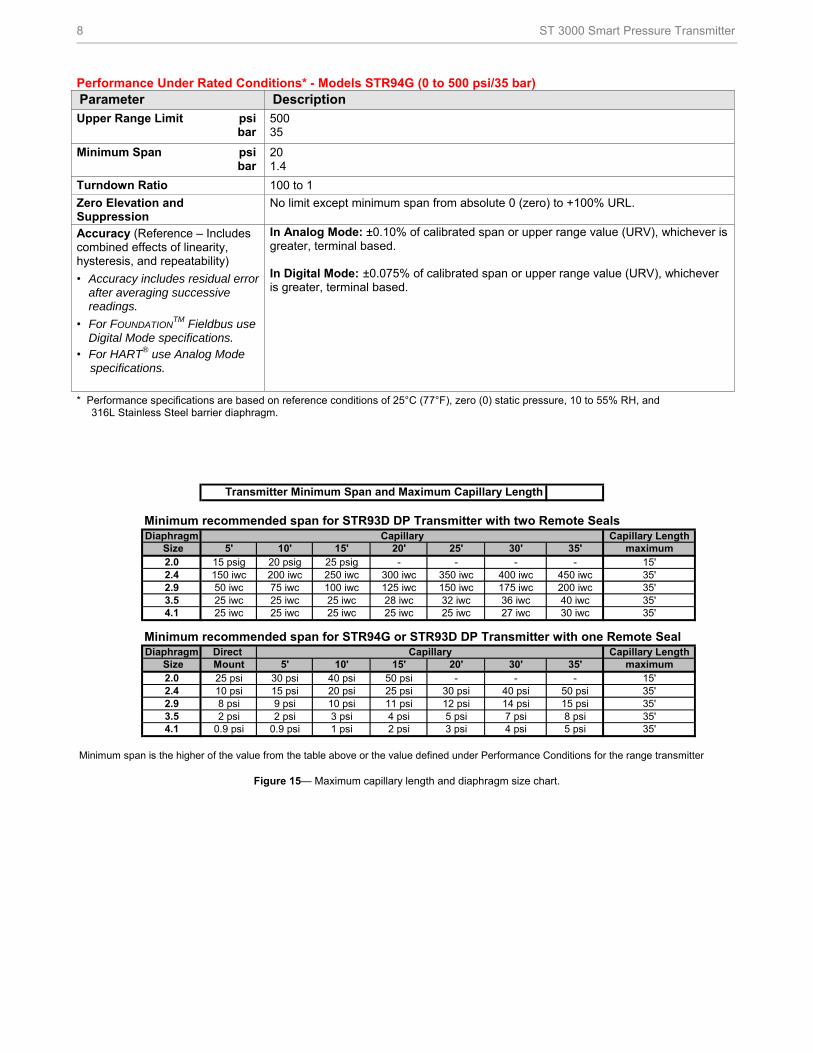
Performance Under Rated Conditions* - Models STR94G (0 to 500 psi/35 bar) Parameter Description Upper Range Limit psi bar
500 35
Minimum Span psi bar
20 1.4
Turndown Ratio 100 to 1
Zero Elevation and Suppression
No limit except minimum span from absolute 0 (zero) to +100% URL.
Accuracy (Reference – Includes combined effects of linearity, hysteresis, and repeatability)
• Accuracy includes residual error after averaging successive readings.
• For FOUNDATIONTM Fieldbus use
Digital Mode specifications. • For HART® use Analog Mode specifications.
In Analog Mode: ±0.10% of calibrated span or upper range value (URV), whichever is greater, terminal based. In Digital Mode: ±0.075% of calibrated span or upper range value (URV), whichever is greater, terminal based.
* Performance specifications are based on reference conditions of 25°C (77°F), zero (0) static pressure, 10 to 55% RH, and 316L Stainless Steel barrier diaphragm.
Transmitter Minimum Span and Maximum Capillary Length
Minimum recommended span for STR93D DP Transmitter with two Remote SealsDiaphragm Capillary Length
Size 5' 10' 15' 20' 25' 30' 35' maximum2.0 15 psig 20 psig 25 psig - - - - 15'2.4 150 iwc 200 iwc 250 iwc 300 iwc 350 iwc 400 iwc 450 iwc 35'2.9 50 iwc 75 iwc 100 iwc 125 iwc 150 iwc 175 iwc 200 iwc 35'3.5 25 iwc 25 iwc 25 iwc 28 iwc 32 iwc 36 iwc 40 iwc 35'4.1 25 iwc 25 iwc 25 iwc 25 iwc 25 iwc 27 iwc 30 iwc 35'
Minimum recommended span for STR94G or STR93D DP Transmitter with one Remote SealDiaphragm Direct Capillary Length
Size Mount 5' 10' 15' 20' 30' 35' maximum2.0 25 psi 30 psi 40 psi 50 psi - - - 15'2.4 10 psi 15 psi 20 psi 25 psi 30 psi 40 psi 50 psi 35'2.9 8 psi 9 psi 10 psi 11 psi 12 psi 14 psi 15 psi 35'3.5 2 psi 2 psi 3 psi 4 psi 5 psi 7 psi 8 psi 35'4.1 0.9 psi 0.9 psi 1 psi 2 psi 3 psi 4 psi 5 psi 35'
Minimum span is the higher of the value from the table above or the value defined under Performance Conditions for the range transmitter
Capillary
Capillary
Figure 15— Maximum capillary length and diaphragm size chart.
ST 3000 Smart Pressure Transmitter 9
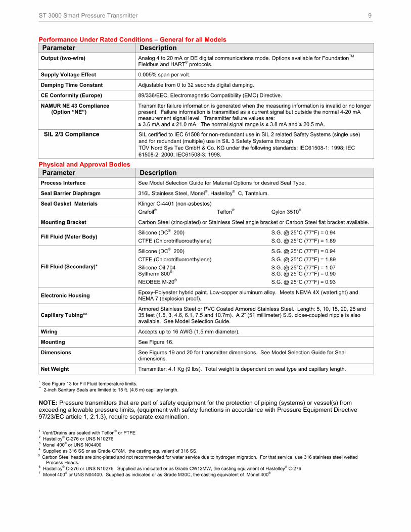
Performance Under Rated Conditions – General for all Models Parameter Description
Output (two-wire) Analog 4 to 20 mA or DE digital communications mode. Options available for FoundationTM Fieldbus and HART® protocols.
Supply Voltage Effect 0.005% span per volt.
Damping Time Constant Adjustable from 0 to 32 seconds digital damping.
CE Conformity (Europe) 89/336/EEC, Electromagnetic Compatibility (EMC) Directive.
NAMUR NE 43 Compliance (Option “NE”)
Transmitter failure information is generated when the measuring information is invalid or no longer present. Failure information is transmitted as a current signal but outside the normal 4-20 mA measurement signal level. Transmitter failure values are: ≤ 3.6 mA and ≥ 21.0 mA. The normal signal range is ≥ 3.8 mA and ≤ 20.5 mA.
SIL 2/3 Compliance SIL certified to IEC 61508 for non-redundant use in SIL 2 related Safety Systems (single use) and for redundant (multiple) use in SIL 3 Safety Systems through TÜV Nord Sys Tec GmbH & Co. KG under the following standards: IEC61508-1: 1998; IEC 61508-2: 2000; IEC61508-3: 1998.
Physical and Approval Bodies Parameter Description
Process Interface See Model Selection Guide for Material Options for desired Seal Type.
Seal Barrier Diaphragm 316L Stainless Steel, Monel®, Hastelloy® C, Tantalum.
Seal Gasket Materials Klinger C-4401 (non-asbestos)
Grafoil® Teflon® Gylon 3510®
Mounting Bracket Carbon Steel (zinc-plated) or Stainless Steel angle bracket or Carbon Steel flat bracket available.
Fill Fluid (Meter Body) Silicone (DC® 200) S.G. @ 25°C (77°F) = 0.94
CTFE (Chlorotrifluoroethylene) S.G. @ 25°C (77°F) = 1.89
Fill Fluid (Secondary)*
Silicone (DC® 200) S.G. @ 25°C (77°F) = 0.94
CTFE (Chlorotrifluoroethylene) S.G. @ 25°C (77°F) = 1.89
Silicone Oil 704 S.G. @ 25°C (77°F) = 1.07 Syltherm 800® S.G. @ 25°C (77°F) = 0.90
NEOBEE M-20® S.G. @ 25°C (77°F) = 0.93
Electronic Housing Epoxy-Polyester hybrid paint. Low-copper aluminum alloy. Meets NEMA 4X (watertight) and NEMA 7 (explosion proof).
Capillary Tubing** Armored Stainless Steel or PVC Coated Armored Stainless Steel. Length: 5, 10, 15, 20, 25 and 35 feet (1.5, 3, 4.6, 6.1, 7.5 and 10.7m). A 2” (51 millimeter) S.S. close-coupled nipple is also available. See Model Selection Guide.
Wiring Accepts up to 16 AWG (1.5 mm diameter).
Mounting See Figure 16.
Dimensions See Figures 19 and 20 for transmitter dimensions. See Model Selection Guide for Seal dimensions.
Net Weight Transmitter: 4.1 Kg (9 lbs). Total weight is dependent on seal type and capillary length.
* See Figure 13 for Fill Fluid temperature limits. ** 2-inch Sanitary Seals are limited to 15 ft. (4.6 m) capillary length.
NOTE: Pressure transmitters that are part of safety equipment for the protection of piping (systems) or vessel(s) from exceeding allowable pressure limits, (equipment with safety functions in accordance with Pressure Equipment Directive 97/23/EC article 1, 2.1.3), require separate examination.
1 Vent/Drains are sealed with Teflon® or PTFE 2 Hastelloy® C-276 or UNS N10276 3 Monel 400® or UNS N04400 4 Supplied as 316 SS or as Grade CF8M, the casting equivalent of 316 SS.
5 Carbon Steel heads are zinc-plated and not recommended for water service due to hydrogen migration. For that service, use 316 stainless steel wetted Process Heads.
6 Hastelloy® C-276 or UNS N10276. Supplied as indicated or as Grade CW12MW, the casting equivalent of Hastelloy® C-276 7 Monel 400® or UNS N04400. Supplied as indicated or as Grade M30C, the casting equivalent of Monel 400®
10 ST 3000 Smart Pressure Transmitter
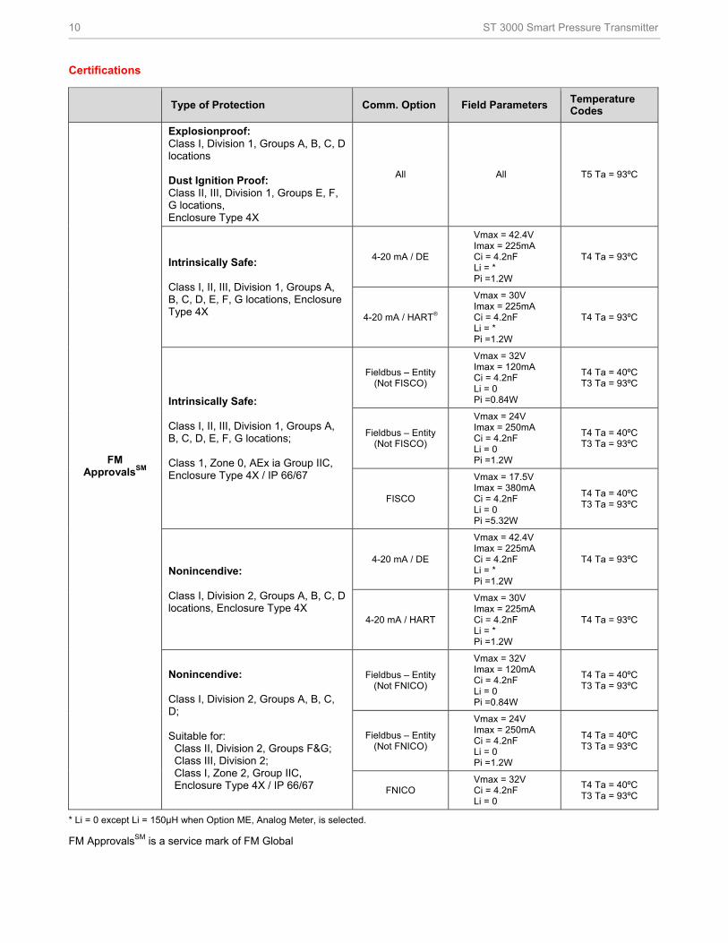
Certifications
Type of Protection Comm. Option Field Parameters Temperature Codes
FM ApprovalsSM
Explosionproof: Class I, Division 1, Groups A, B, C, D locations Dust Ignition Proof: Class II, III, Division 1, Groups E, F, G locations, Enclosure Type 4X
All All T5 Ta = 93ºC
Intrinsically Safe: Class I, II, III, Division 1, Groups A, B, C, D, E, F, G locations, Enclosure Type 4X
4-20 mA / DE
Vmax = 42.4V Imax = 225mA Ci = 4.2nF Li = * Pi =1.2W
T4 Ta = 93ºC
4-20 mA / HART®
Vmax = 30V Imax = 225mA Ci = 4.2nF Li = * Pi =1.2W
T4 Ta = 93ºC
Intrinsically Safe: Class I, II, III, Division 1, Groups A, B, C, D, E, F, G locations; Class 1, Zone 0, AEx ia Group IIC, Enclosure Type 4X / IP 66/67
Fieldbus – Entity (Not FISCO)
Vmax = 32V Imax = 120mA Ci = 4.2nF Li = 0 Pi =0.84W
T4 Ta = 40ºC T3 Ta = 93ºC
Fieldbus – Entity (Not FISCO)
Vmax = 24V Imax = 250mA Ci = 4.2nF Li = 0 Pi =1.2W
T4 Ta = 40ºC T3 Ta = 93ºC
FISCO
Vmax = 17.5V Imax = 380mA Ci = 4.2nF Li = 0 Pi =5.32W
T4 Ta = 40ºC T3 Ta = 93ºC
Nonincendive: Class I, Division 2, Groups A, B, C, D locations, Enclosure Type 4X
4-20 mA / DE
Vmax = 42.4V Imax = 225mA Ci = 4.2nF Li = * Pi =1.2W
T4 Ta = 93ºC
4-20 mA / HART
Vmax = 30V Imax = 225mA Ci = 4.2nF Li = * Pi =1.2W
T4 Ta = 93ºC
Nonincendive: Class I, Division 2, Groups A, B, C, D; Suitable for: Class II, Division 2, Groups F&G; Class III, Division 2; Class I, Zone 2, Group IIC, Enclosure Type 4X / IP 66/67
Fieldbus – Entity (Not FNICO)
Vmax = 32V Imax = 120mA Ci = 4.2nF Li = 0 Pi =0.84W
T4 Ta = 40ºC T3 Ta = 93ºC
Fieldbus – Entity (Not FNICO)
Vmax = 24V Imax = 250mA Ci = 4.2nF Li = 0 Pi =1.2W
T4 Ta = 40ºC T3 Ta = 93ºC
FNICO Vmax = 32V Ci = 4.2nF Li = 0
T4 Ta = 40ºC T3 Ta = 93ºC
* Li = 0 except Li = 150µH when Option ME, Analog Meter, is selected.
FM ApprovalsSM is a service mark of FM Global
ST 3000 Smart Pressure Transmitter 11
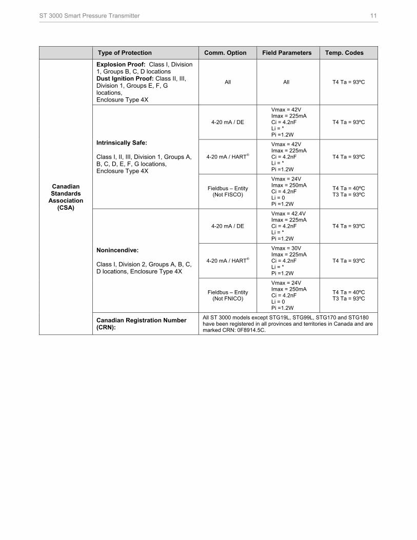
Type of Protection Comm. Option Field Parameters Temp. Codes
Canadian Standards
Association (CSA)
Explosion Proof: Class I, Division 1, Groups B, C, D locations Dust Ignition Proof: Class II, III, Division 1, Groups E, F, G locations, Enclosure Type 4X
All All T4 Ta = 93ºC
Intrinsically Safe: Class I, II, III, Division 1, Groups A, B, C, D, E, F, G locations, Enclosure Type 4X
4-20 mA / DE
Vmax = 42V Imax = 225mA Ci = 4.2nF Li = * Pi =1.2W
T4 Ta = 93ºC
4-20 mA / HART®
Vmax = 42V Imax = 225mA Ci = 4.2nF Li = * Pi =1.2W
T4 Ta = 93ºC
Fieldbus – Entity (Not FISCO)
Vmax = 24V Imax = 250mA Ci = 4.2nF Li = 0 Pi =1.2W
T4 Ta = 40ºC T3 Ta = 93ºC
Nonincendive: Class I, Division 2, Groups A, B, C, D locations, Enclosure Type 4X
4-20 mA / DE
Vmax = 42.4V Imax = 225mA Ci = 4.2nF Li = * Pi =1.2W
T4 Ta = 93ºC
4-20 mA / HART®
Vmax = 30V Imax = 225mA Ci = 4.2nF Li = * Pi =1.2W
T4 Ta = 93ºC
Fieldbus – Entity (Not FNICO)
Vmax = 24V Imax = 250mA Ci = 4.2nF Li = 0 Pi =1.2W
T4 Ta = 40ºC T3 Ta = 93ºC
Canadian Registration Number (CRN):
All ST 3000 models except STG19L, STG99L, STG170 and STG180 have been registered in all provinces and territories in Canada and are marked CRN: 0F8914.5C.
12 ST 3000 Smart Pressure Transmitter
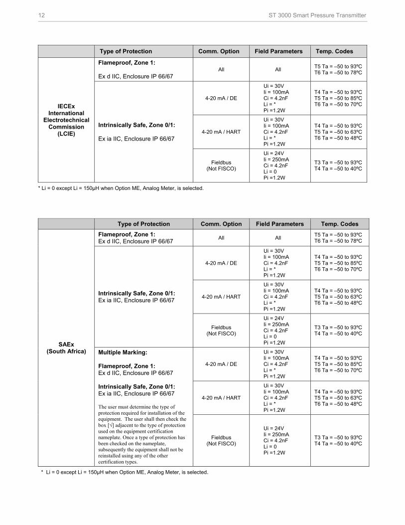
Type of Protection Comm. Option Field Parameters Temp. Codes
IECEx International
Electrotechnical Commission
(LCIE)
Flameproof, Zone 1: Ex d IIC, Enclosure IP 66/67
All All T5 Ta = –50 to 93ºC T6 Ta = –50 to 78ºC
Intrinsically Safe, Zone 0/1: Ex ia IIC, Enclosure IP 66/67
4-20 mA / DE
Ui = 30V Ii = 100mA Ci = 4.2nF Li = * Pi =1.2W
T4 Ta = –50 to 93ºC T5 Ta = –50 to 85ºC T6 Ta = –50 to 70ºC
4-20 mA / HART
Ui = 30V Ii = 100mA Ci = 4.2nF Li = * Pi =1.2W
T4 Ta = –50 to 93ºC T5 Ta = –50 to 63ºC T6 Ta = –50 to 48ºC
Fieldbus (Not FISCO)
Ui = 24V Ii = 250mA Ci = 4.2nF Li = 0 Pi =1.2W
T3 Ta = –50 to 93ºC T4 Ta = –50 to 40ºC
* Li = 0 except Li = 150µH when Option ME, Analog Meter, is selected.
Type of Protection Comm. Option Field Parameters Temp. Codes
SAEx (South Africa)
Flameproof, Zone 1: Ex d IIC, Enclosure IP 66/67
All All T5 Ta = –50 to 93ºC T6 Ta = –50 to 78ºC
Intrinsically Safe, Zone 0/1: Ex ia IIC, Enclosure IP 66/67
4-20 mA / DE
Ui = 30V Ii = 100mA Ci = 4.2nF Li = * Pi =1.2W
T4 Ta = –50 to 93ºC T5 Ta = –50 to 85ºC T6 Ta = –50 to 70ºC
4-20 mA / HART
Ui = 30V Ii = 100mA Ci = 4.2nF Li = * Pi =1.2W
T4 Ta = –50 to 93ºC T5 Ta = –50 to 63ºC T6 Ta = –50 to 48ºC
Fieldbus (Not FISCO)
Ui = 24V Ii = 250mA Ci = 4.2nF Li = 0 Pi =1.2W
T3 Ta = –50 to 93ºC T4 Ta = –50 to 40ºC
Multiple Marking: Flameproof, Zone 1: Ex d IIC, Enclosure IP 66/67 Intrinsically Safe, Zone 0/1: Ex ia IIC, Enclosure IP 66/67 The user must determine the type of protection required for installation of the equipment. The user shall then check the box [√] adjacent to the type of protection used on the equipment certification nameplate. Once a type of protection has been checked on the nameplate, subsequently the equipment shall not be reinstalled using any of the other certification types.
4-20 mA / DE
Ui = 30V Ii = 100mA Ci = 4.2nF Li = * Pi =1.2W
T4 Ta = –50 to 93ºC T5 Ta = –50 to 85ºC T6 Ta = –50 to 70ºC
4-20 mA / HART
Ui = 30V Ii = 100mA Ci = 4.2nF Li = * Pi =1.2W
T4 Ta = –50 to 93ºC T5 Ta = –50 to 63ºC T6 Ta = –50 to 48ºC
Fieldbus (Not FISCO)
Ui = 24V Ii = 250mA Ci = 4.2nF Li = 0 Pi =1.2W
T3 Ta = –50 to 93ºC T4 Ta = –50 to 40ºC
* Li = 0 except Li = 150µH when Option ME, Analog Meter, is selected.
ST 3000 Smart Pressure Transmitter 13
Type of Protection Comm. Option Field Parameters Temp. Codes
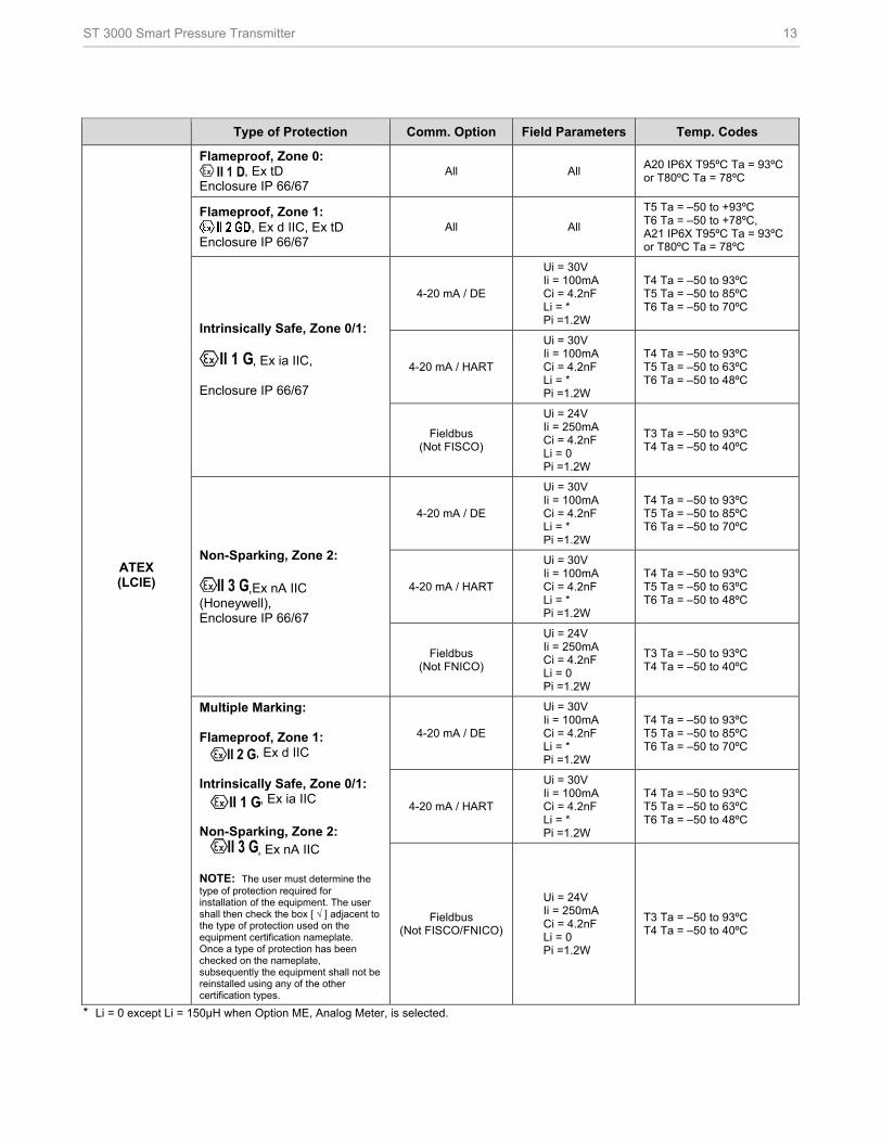
ATEX (LCIE)
Flameproof, Zone 0: , Ex tD
Enclosure IP 66/67 All All
A20 IP6X T95ºC Ta = 93ºC or T80ºC Ta = 78ºC
Flameproof, Zone 1: , Ex d IIC, Ex tD
Enclosure IP 66/67 All All
T5 Ta = –50 to +93ºC T6 Ta = –50 to +78ºC, A21 IP6X T95ºC Ta = 93ºC or T80ºC Ta = 78ºC
Intrinsically Safe, Zone 0/1:
, Ex ia IIC, Enclosure IP 66/67
4-20 mA / DE
Ui = 30V Ii = 100mA Ci = 4.2nF Li = * Pi =1.2W
T4 Ta = –50 to 93ºC T5 Ta = –50 to 85ºC T6 Ta = –50 to 70ºC
4-20 mA / HART
Ui = 30V Ii = 100mA Ci = 4.2nF Li = * Pi =1.2W
T4 Ta = –50 to 93ºC T5 Ta = –50 to 63ºC T6 Ta = –50 to 48ºC
Fieldbus (Not FISCO)
Ui = 24V Ii = 250mA Ci = 4.2nF Li = 0 Pi =1.2W
T3 Ta = –50 to 93ºC T4 Ta = –50 to 40ºC
Non-Sparking, Zone 2:
,Ex nA IIC (Honeywell), Enclosure IP 66/67
4-20 mA / DE
Ui = 30V Ii = 100mA Ci = 4.2nF Li = * Pi =1.2W
T4 Ta = –50 to 93ºC T5 Ta = –50 to 85ºC T6 Ta = –50 to 70ºC
4-20 mA / HART
Ui = 30V Ii = 100mA Ci = 4.2nF Li = * Pi =1.2W
T4 Ta = –50 to 93ºC T5 Ta = –50 to 63ºC T6 Ta = –50 to 48ºC
Fieldbus (Not FNICO)
Ui = 24V Ii = 250mA Ci = 4.2nF Li = 0 Pi =1.2W
T3 Ta = –50 to 93ºC T4 Ta = –50 to 40ºC
Multiple Marking: Flameproof, Zone 1: , Ex d IIC Intrinsically Safe, Zone 0/1: , Ex ia IIC Non-Sparking, Zone 2: , Ex nA IIC NOTE: The user must determine the type of protection required for installation of the equipment. The user shall then check the box [ √ ] adjacent to the type of protection used on the equipment certification nameplate. Once a type of protection has been checked on the nameplate, subsequently the equipment shall not be reinstalled using any of the other certification types.
4-20 mA / DE
Ui = 30V Ii = 100mA Ci = 4.2nF Li = * Pi =1.2W
T4 Ta = –50 to 93ºC T5 Ta = –50 to 85ºC T6 Ta = –50 to 70ºC
4-20 mA / HART
Ui = 30V Ii = 100mA Ci = 4.2nF Li = * Pi =1.2W
T4 Ta = –50 to 93ºC T5 Ta = –50 to 63ºC T6 Ta = –50 to 48ºC
Fieldbus (Not FISCO/FNICO)
Ui = 24V Ii = 250mA Ci = 4.2nF Li = 0 Pi =1.2W
T3 Ta = –50 to 93ºC T4 Ta = –50 to 40ºC
* Li = 0 except Li = 150µH when Option ME, Analog Meter, is selected.
14 ST 3000 Smart Pressure Transmitter
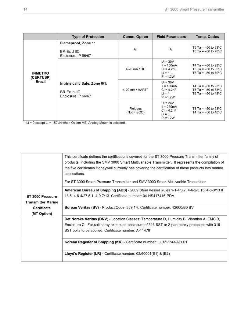
Type of Protection Comm. Option Field Parameters Temp. Codes
INMETRO (CERTUSP)
Brazil
Flameproof, Zone 1: BR-Ex d IIC Enclosure IP 66/67
All All T5 Ta = –50 to 93ºC T6 Ta = –50 to 78ºC
Intrinsically Safe, Zone 0/1: BR-Ex ia IIC Enclosure IP 66/67
4-20 mA / DE
Ui = 30V Ii = 100mA Ci = 4.2nF Li = * Pi =1.2W
T4 Ta = –50 to 93ºC T5 Ta = –50 to 85ºC T6 Ta = –50 to 70ºC
4-20 mA / HART®
Ui = 30V Ii = 100mA Ci = 4.2nF Li = * Pi =1.2W
T4 Ta = –50 to 93ºC T5 Ta = –50 to 63ºC T6 Ta = –50 to 48ºC
Fieldbus (Not FISCO)
Ui = 24V Ii = 250mA Ci = 4.2nF Li = 0 Pi =1.2W
T3 Ta = –50 to 93ºC T4 Ta = –50 to 40ºC
* Li = 0 except Li = 150µH when Option ME, Analog Meter, is selected.
ST 3000 Pressure
Transmitter Marine
Certificate
(MT Option)
This certificate defines the certifications covered for the ST 3000 Pressure Transmitter family of
products, including the SMV 3000 Smart Multivariable Transmitter. It represents the compilation of
the five certificates Honeywell currently has covering the certification of these products into marine
applications.
For ST 3000 Smart Pressure Transmitter and SMV 3000 Smart Multivarible Transmitter
American Bureau of Shipping (ABS) - 2009 Steel Vessel Rules 1-1-4/3.7, 4-6-2/5.15, 4-8-3/13 &
13.5, 4-8-4/27.5.1, 4-9-7/13. Certificate number: 04-HS417416-PDA
Bureau Veritas (BV) - Product Code: 389:1H. Certificate number: 12660/B0 BV
Det Norske Veritas (DNV) - Location Classes: Temperature D, Humidity B, Vibration A, EMC B,
Enclosure C. For salt spray exposure; enclosure of 316 SST or 2-part epoxy protection with 316
SST bolts to be applied. Certificate number: A-11476
Korean Register of Shipping (KR) - Certificate number: LOX17743-AE001
Lloyd's Register (LR) - Certificate number: 02/60001(E1) & (E2)
ST 3000 Smart Pressure Transmitter 15
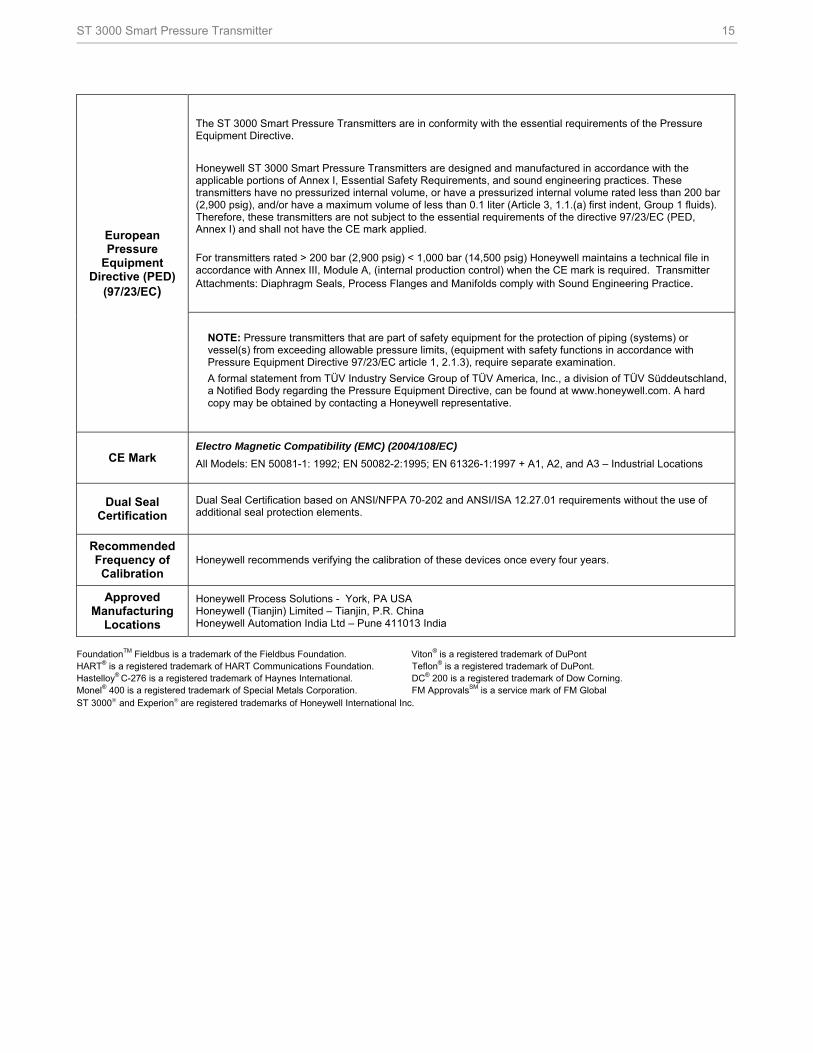
European Pressure
Equipment Directive (PED)
(97/23/EC)
The ST 3000 Smart Pressure Transmitters are in conformity with the essential requirements of the Pressure Equipment Directive.
Honeywell ST 3000 Smart Pressure Transmitters are designed and manufactured in accordance with the applicable portions of Annex I, Essential Safety Requirements, and sound engineering practices. These transmitters have no pressurized internal volume, or have a pressurized internal volume rated less than 200 bar (2,900 psig), and/or have a maximum volume of less than 0.1 liter (Article 3, 1.1.(a) first indent, Group 1 fluids). Therefore, these transmitters are not subject to the essential requirements of the directive 97/23/EC (PED, Annex I) and shall not have the CE mark applied.
For transmitters rated > 200 bar (2,900 psig) < 1,000 bar (14,500 psig) Honeywell maintains a technical file in accordance with Annex III, Module A, (internal production control) when the CE mark is required. Transmitter Attachments: Diaphragm Seals, Process Flanges and Manifolds comply with Sound Engineering Practice.
NOTE: Pressure transmitters that are part of safety equipment for the protection of piping (systems) or vessel(s) from exceeding allowable pressure limits, (equipment with safety functions in accordance with Pressure Equipment Directive 97/23/EC article 1, 2.1.3), require separate examination.
A formal statement from TÜV Industry Service Group of TÜV America, Inc., a division of TÜV Süddeutschland, a Notified Body regarding the Pressure Equipment Directive, can be found at www.honeywell.com. A hard copy may be obtained by contacting a Honeywell representative.
CE Mark Electro Magnetic Compatibility (EMC) (2004/108/EC) All Models: EN 50081-1: 1992; EN 50082-2:1995; EN 61326-1:1997 + A1, A2, and A3 – Industrial Locations
Dual Seal Certification
Dual Seal Certification based on ANSI/NFPA 70-202 and ANSI/ISA 12.27.01 requirements without the use of additional seal protection elements.
Recommended Frequency of Calibration
Honeywell recommends verifying the calibration of these devices once every four years.
Approved Manufacturing
Locations
Honeywell Process Solutions - York, PA USA Honeywell (Tianjin) Limited – Tianjin, P.R. China Honeywell Automation India Ltd – Pune 411013 India
FoundationTM Fieldbus is a trademark of the Fieldbus Foundation. Viton® is a registered trademark of DuPont HART® is a registered trademark of HART Communications Foundation. Teflon® is a registered trademark of DuPont. Hastelloy® C-276 is a registered trademark of Haynes International. DC® 200 is a registered trademark of Dow Corning. Monel® 400 is a registered trademark of Special Metals Corporation. FM ApprovalsSM is a service mark of FM Global ST 3000 and Experion are registered trademarks of Honeywell International Inc.
16 ST 3000 Smart Pressure Transmitter
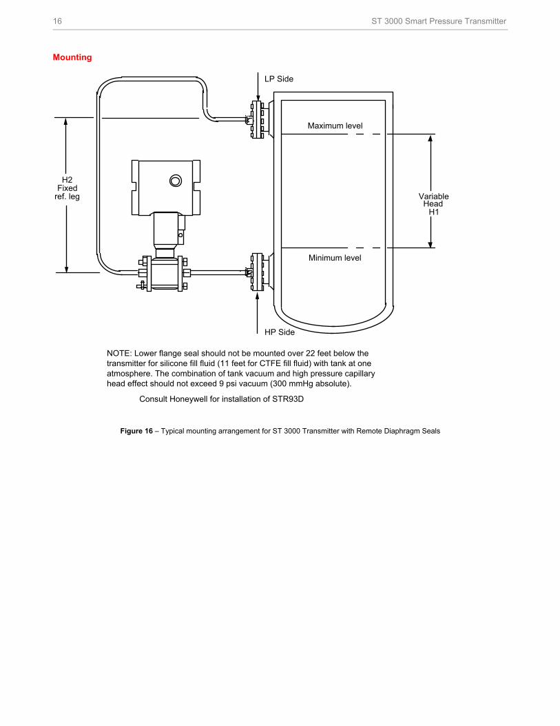
Mounting
NOTE: Lower flange seal should not be mounted over 22 feet below the transmitter for silicone fill fluid (11 feet for CTFE fill fluid) with tank at one atmosphere. The combination of tank vacuum and high pressure capillary head effect should not exceed 9 psi vacuum (300 mmHg absolute).
VariableHead
H1
LP Side
HP Side
ref. leg
H2Fixed
Maximum level
Minimum level.
Consult Honeywell for installation of STR93D
Figure 16 – Typical mounting arrangement for ST 3000 Transmitter with Remote Diaphragm Seals
ST 3000 Smart Pressure Transmitter 17
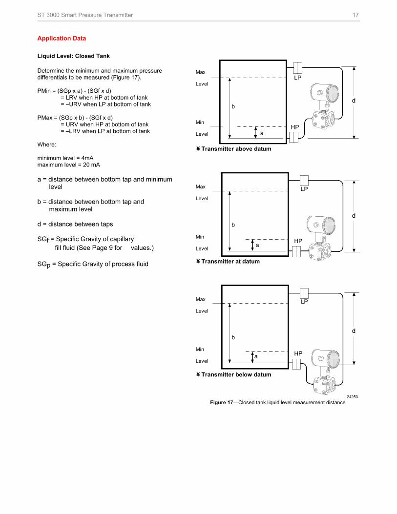
Application Data Liquid Level: Closed Tank Determine the minimum and maximum pressure differentials to be measured (Figure 17). PMin = (SGp x a) - (SGf x d) = LRV when HP at bottom of tank = –URV when LP at bottom of tank PMax = (SGp x b) - (SGf x d) = URV when HP at bottom of tank = –LRV when LP at bottom of tank Where: minimum level = 4mA maximum level = 20 mA a = distance between bottom tap and minimum
level b = distance between bottom tap and
maximum level d = distance between taps SGf = Specific Gravity of capillary fill fluid (See Page 9 for values.) SGp = Specific Gravity of process fluid
b
a
LP
HP
24253
Max
Level
Min
Level
¥ Transmitter above datum
LP
HP
b
a
Max
Level
Min
Level
¥ Transmitter at datum
LP
HP
b
a
Max
Level
Min
Level
¥ Transmitter below datum
Figure 17—Closed tank liquid level measurement distance
18 ST 3000 Smart Pressure Transmitter
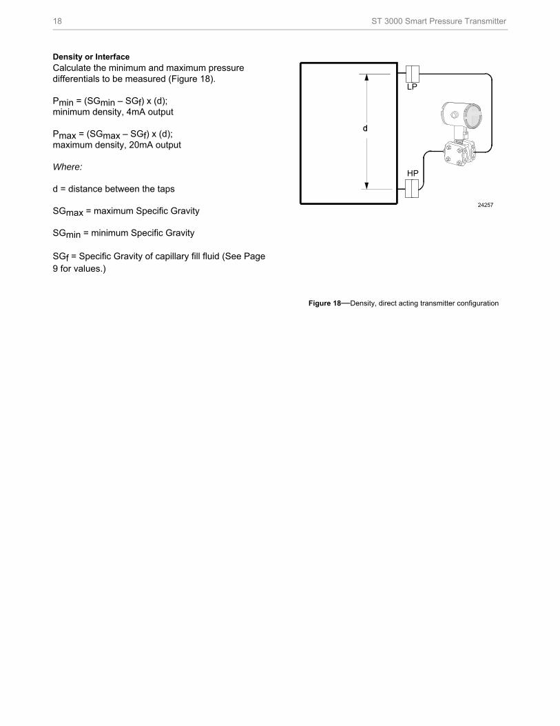
Density or Interface Calculate the minimum and maximum pressure differentials to be measured (Figure 18). Pmin = (SGmin – SGf) x (d); minimum density, 4mA output Pmax = (SGmax – SGf) x (d); maximum density, 20mA output Where: d = distance between the taps SGmax = maximum Specific Gravity SGmin = minimum Specific Gravity
SGf = Specific Gravity of capillary fill fluid (See Page 9 for values.)
LP
HP
24257
Figure 18—Density, direct acting transmitter configuration
ST 3000 Smart Pressure Transmitter 19
Reference Dimensions
millimeters
inches
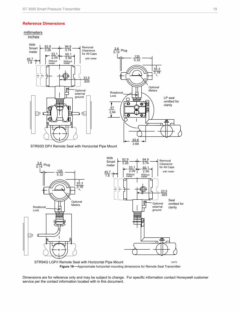
STR93D DP/I Remote Seal with Horizontal Pipe Mount
STR94G LGP/I Remote Seal with Horizontal Pipe Mount 24272
Seal omitted for clarity
with meter
Optional external ground
45.7 1.8
53.1 2.09
Removal Clearance for All Caps
82.9 3.26
With Smart meter
Withoutmeter
94.9 3.74
65.1 2.56
Withoutmeter
23.5 .925
Rotational Lock
3.6 0.14
Plug
55.3 2.18
Optional Meters
135 5.32
672.64
93.6
LP seal omitted for clarity
Rotational Lock
3.6 0.14
Plug
55.3 2.18
Optional Meters
135 5.32
3.69
with meter
Optional external ground
45.7 1.8
53.1 2.09
Removal Clearance for All Caps
82.9 3.26
With Smart meter
Withoutmeter
94.9 3.7465.1 2.56
Withoutmeter
23.5 .925
Figure 19—Approximate horizontal mounting dimensions for Remote Seal Transmitter
Dimensions are for reference only and may be subject to change. For specific information contact Honeywell customer service per the contact information located with in this document.
20 ST 3000 Smart Pressure Transmitter
Reference Dimensions millimeters
inches
Sealomitted forclarity
Optionalexternalground
with meter45.71.8
53.12.09
RemovalClearancefor All Caps
82.93.26
WithSmart meter
Withoutmeter
94.93.74
65.12.56
Withoutmeter
23.5.925
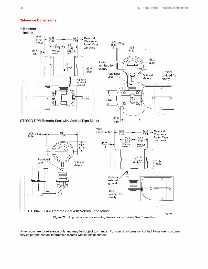
STR93D DP/I Remote Seal with Vertical Pipe Mount
Optionalexternalground
with meter45.71.8
53.12.09
RemovalClearancefor All Caps
82.93.26
WithSmartmeter
Withoutmeter
94.93.74
65.12.56
Withoutmeter
23.5.925
STR94G LGP/I Remote Seal with Vertical Pipe Mount
RotationalLock
3.60.14
Plug
55.32.18
OptionalMeters
1355.32
24273
Sealomitted forclarity
LP sealomitted forclarity
672.64
RotationalLock
3.60.14
Plug
1355.32
55.32.18
OptionalMeters
3.6993.6
Figure 20—Approximate vertical mounting dimensions for Remote Seal Transmitter
Dimensions are for reference only and may be subject to change. For specific information contact Honeywell customer service per the contact information located with in this document.
ST 3000 Smart Pressure Transmitter 21
Dimensions and Drawings Flush Flanged Seal
22 ST 3000 Smart Pressure Transmitter
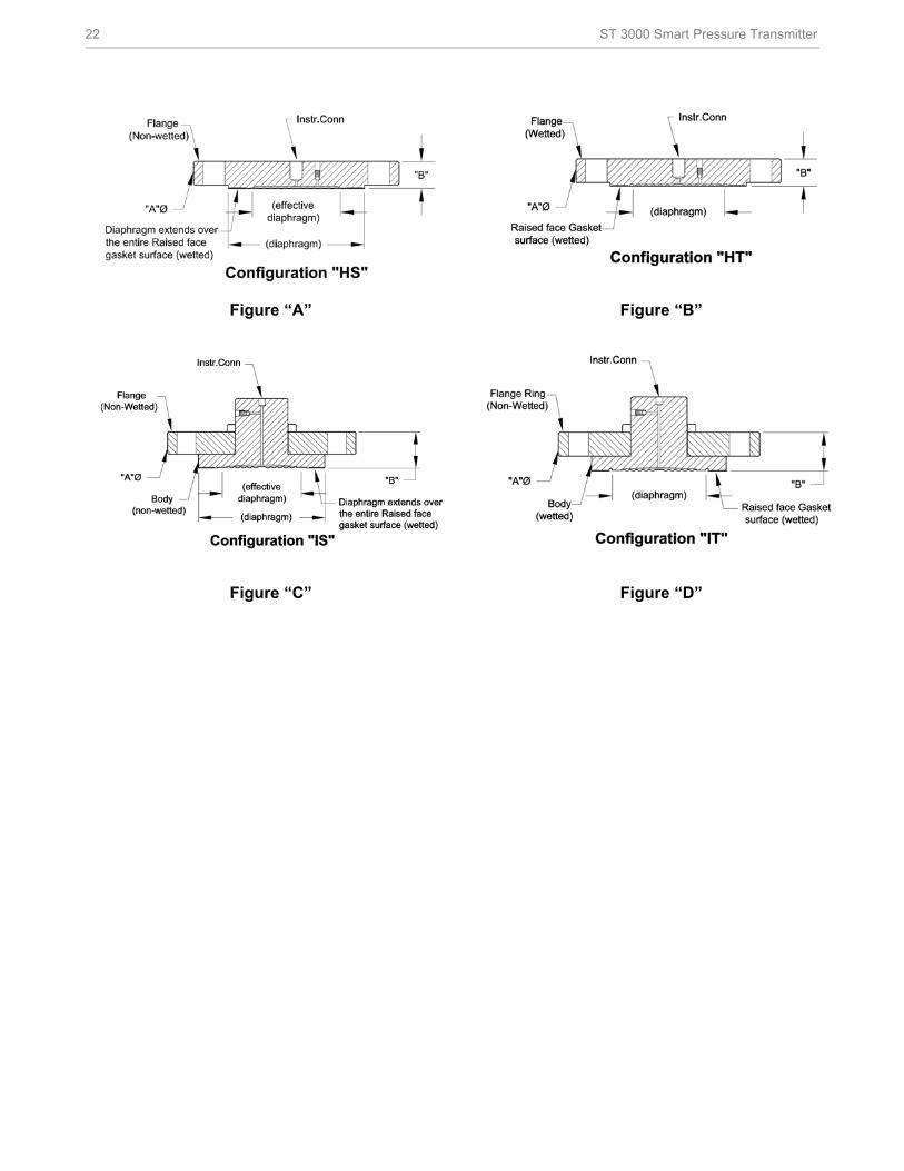
Figure “A” Figure “B”
Figure “C” Figure “D”
ST 3000 Smart Pressure Transmitter 23
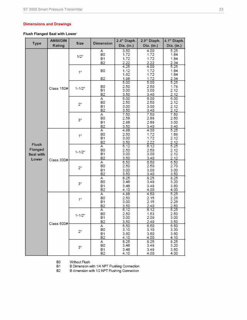
Dimensions and Drawings Flush Flanged Seal with Lower
24 ST 3000 Smart Pressure Transmitter
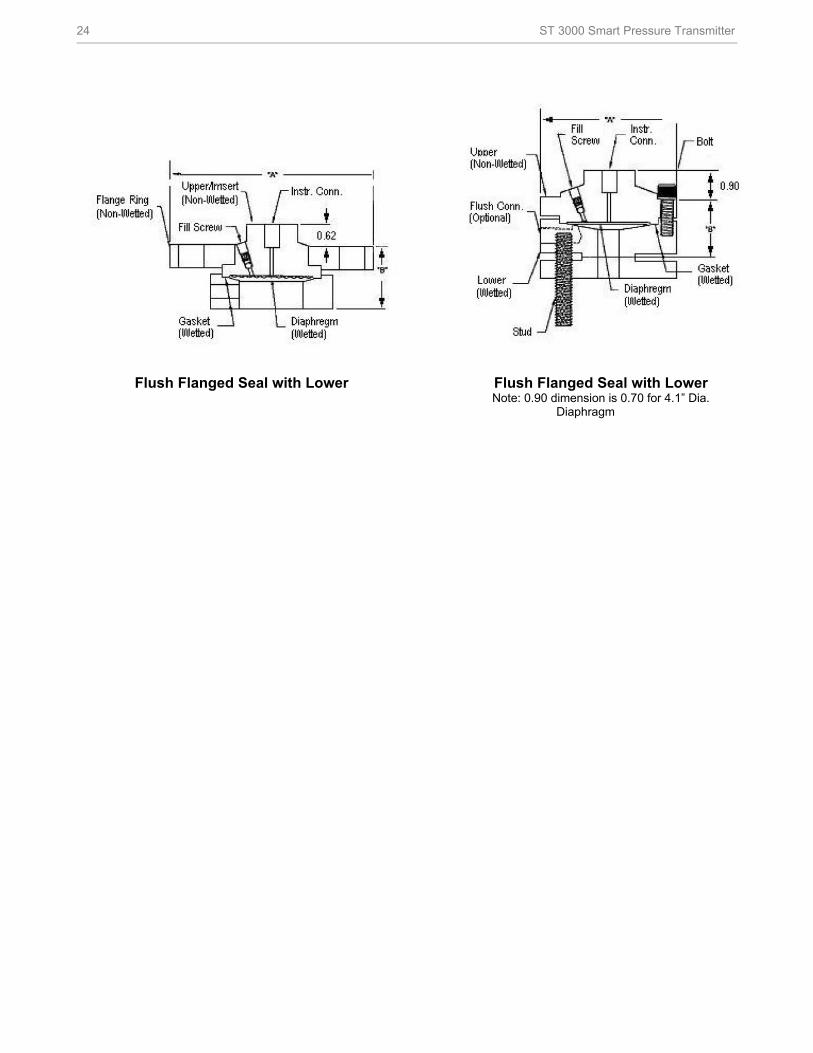
Flush Flanged Seal with Lower Flush Flanged Seal with Lower Note: 0.90 dimension is 0.70 for 4.1” Dia.
Diaphragm
ST 3000 Smart Pressure Transmitter 25
Dimensions and Drawings Flanged Seal with Extended Diaphragm
Flange Extended Seal Pancake Seal
Pancake Flange Seal Chemical Tee “Taylor Wedge” Seal
Chemical Tee “Taylor Wedge” Seal
26 ST 3000 Smart Pressure Transmitter
Seal with Threaded Process Connection
Threaded Process Connection Seal
Sanitary Seal
Sanitary Seal
ST 3000 Smart Pressure Transmitter 27
Saddle Seal
3” Saddle Seal
4” Saddle Seal
Calibration Rings
Calibration Ring
28 ST 3000 Smart Pressure Transmitter
Options
• High Accuracy (Option HA)
Extends applicable S100 models to ±0.025% analog
reference accuracy.
• Angle Mounting Bracket (Options MB, MX, SB, SX,
FB)
The angle mounting bracket is available in either zinc-
plated carbon steel or stainless steel and is suitable for
horizontal or vertical mounting on a two inch (50
millimeter) pipe, as well as wall mounting. An optional
flat mounting bracket is also available in carbon steel
for two inch (50 millimeter) pipe mounting. An option
also exists for Marine approved mounting brackets
used with Marine certification options.
• Indicating Meter (Options ME and SM)
Two integral meter options are available. An analog
meter (option ME) is available with a dual 0 to 10
square root and 0 to 100% linear scale. The Smart
Meter (option SM) provides an LCD display for both
analog and digital output and can be configured to
display pressure in selected engineering units.
• HART® Output Protocol (Options HC and H6)
Optional electronic modules for the ST 3000 provide
HART® Protocol compatibility in either HART® 5.x or
6.x formats. Transmitters with a HART® Option are
compatible with any HART® enabled system that
provides 5.x or 6.x format support.
• FoundationTM Fieldbus Output (Option FF)
Equips transmitter with FF protocol for use in 31.25
kbit/s FF networks. See document 34-ST-03-72 for
additional information on ST 3000 Fieldbus
transmitters.
• SIL2/SIL3 Certification (Option SL)
This ST 3000 product is available for use with safety
systems. With the SL option, we are fully certified to
SIL 2 capability for single transmitters and SIL 3
capability for multiple transmitter use through TÜV
Nord Sys Tec GmbH & Co. KG. We are in compliance
with the following SIL standards:
IEC 61508-1: 1998
IEC 61508-2: 2000
IEC 61508-3: 1998
• Lightning Protection (Option LP)
A terminal block is available with circuitry that protects
the transmitter from transient surges induced by nearby
lightning strikes.
• NAMUR NE43 Compliance (Option NE)
This option provides software the meets the NAMUR
NE43 requirements for failsafe software. Transmitter
failure information is generated when the measuring
information is no longer valid.
Transmitter failure values are ≤ 3.6 mA and ≥ 21.0 mA.
The normal ST 3000 ranges are ≤ 3.8 mA and ≥ 20.8
mA.
• Write Protection (Options WP and WX)
Provides the capability to hardwire write-protect
installed transmitter configurations.
• Stainless Steel Tagging (Option TG)
Up to 30 characters can be added on the stainless
steel nameplate mounted on the transmitter’s
electronics housing at no extra cost. A stainless steel
wired on tag with additional data of up to 4 lines of 28
characters is also available. The number of characters
for tagging includes spaces.
• Transmitter Configuration (Options TC and FC)
With Option TC, the factory can configure the analog,
DE or HART® transmitter’s linear/square root
extraction, damping time, LRV, URV and mode
(analog/digital) and enter an ID tag of up to eight
characters and scratchpad information as specified.
With Option FC, the Device ID, Transmitter Tag, Unit
Level Node Address, Output Mode and Damping Time
Constants can be specified.
• Custom Calibration and ID in Memory (Option CC)
The factory can calibrate any range within the scope of
the transmitter’s range and enter an ID tag of up to
eight characters in the transmitter’s memory.
• Indicator Configuration (Option CI)
Provides custom configuration of Smart Meters.
• Lifetime Warranty (Option WL)
Extends limited 1-year warranty policy to 15 years for
ST 3000 S100 pressure transmitters. See Honeywell
Terms and Conditions.
ST 3000 Smart Pressure Transmitter 29
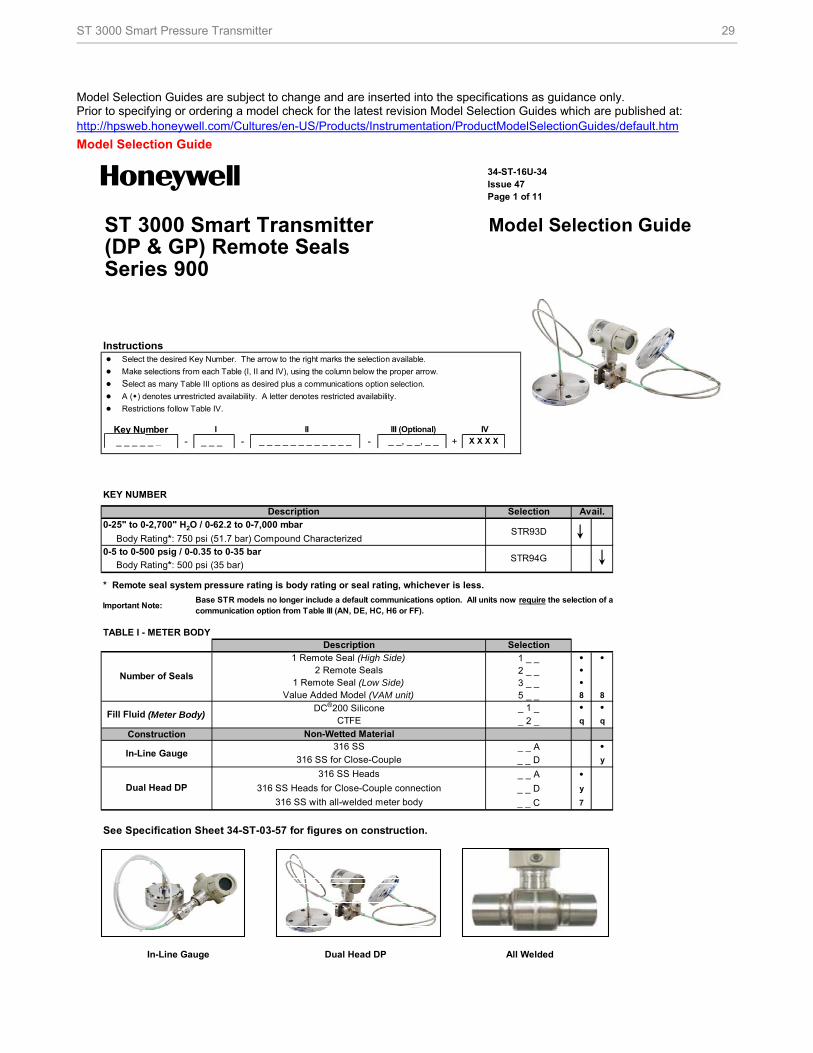
Model Selection Guides are subject to change and are inserted into the specifications as guidance only. Prior to specifying or ordering a model check for the latest revision Model Selection Guides which are published at: http://hpsweb.honeywell.com/Cultures/en-US/Products/Instrumentation/ProductModelSelectionGuides/default.htm
Model Selection Guide
34-ST-16U-34Issue 47Page 1 of 11
ST 3000 Smart Transmitter Model Selection Guide(DP & GP) Remote SealsSeries 900
Instructions ● Select the desired Key Number. The arrow to the right marks the selection available.
● Make selections from each Table (I, II and IV), using the column below the proper arrow.
● Select as many Table III options as desired plus a communications option selection.
● A () denotes unrestricted availability. A letter denotes restricted availability.
● Restrictions follow Table IV.
Key Number _ _ _ _ _ _ - _ _ _ - - +
KEY NUMBER
* Remote seal system pressure rating is body rating or seal rating, whichever is less.
Important Note:
TABLE I - METER BODY
1 _ _ • •2 _ _ •3 _ _ •5 _ _ 8 8
_ 1 _ • •_ 2 _ q q
Construction_ _ A •_ _ D y
_ _ A •_ _ D y
_ _ C 7
See Specification Sheet 34-ST-03-57 for figures on construction.
In-Line Gauge Dual Head DP All Welded
_ _ _ _ _ _ _ _ _ _ _ _ _ _, _ _, _ _
Description
316 SS Heads for Close-Couple connection
1 Remote Seal (High Side)
316 SS Heads
Dual Head DP
Selection
0-25" to 0-2,700" H2O / 0-62.2 to 0-7,000 mbar
2 Remote Seals
316 SS for Close-Couple
DC®200 Silicone
316 SS
CTFEFill Fluid (Meter Body)
Avail.
0-5 to 0-500 psig / 0-0.35 to 0-35 bar
Value Added Model (VAM unit)
In-Line Gauge
I II
Body Rating*: 500 psi (35 bar)
Body Rating*: 750 psi (51.7 bar) Compound Characterized
III (Optional)
X X X X
IV
STR94G
Description
STR93D
Selection
Number of Seals1 Remote Seal (Low Side)
316 SS with all-welded meter body
Base STR models no longer include a default communications option. All units now require the selection of a communication option from Table III (AN, DE, HC, H6 or FF).
Non-Wetted Material
30 ST 3000 Smart Pressure Transmitter
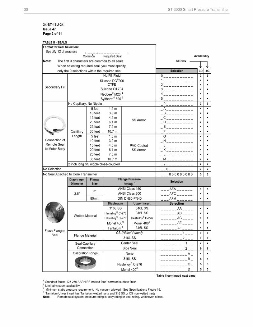
34-ST-16U-34Issue 47Page 2 of 11
TABLE II - SEALS
Format for Seal Selection:
Specify 12 characters _ _ _ _ _ _ _ _ _ _ _ _Common Required Seal
Note: The first 3 characters are common to all seals. STR9xx
When selecting required seal, you must specify
only the 9 selections within the required seal. 3D 4G
0 _ _ _ _ _ _ _ _ _ _ _ 3 3
1 _ _ _ _ _ _ _ _ _ _ _ • •2 _ _ _ _ _ _ _ _ _ _ _ • •3 _ _ _ _ _ _ _ _ _ _ _ • •4 _ _ _ _ _ _ _ _ _ _ _ • •5 _ _ _ _ _ _ _ _ _ _ _ • •_ 0 _ _ _ _ _ _ _ _ _ _ 3 3
5 feet 1.5 m _ A _ _ _ _ _ _ _ _ _ _ • •10 feet 3.0 m _ B _ _ _ _ _ _ _ _ _ _ • •15 feet 4.5 m _ C _ _ _ _ _ _ _ _ _ _ • •20 feet 6.1 m _ D _ _ _ _ _ _ _ _ _ _ • •25 feet 7.5 m _ E _ _ _ _ _ _ _ _ _ _ • •35 feet 10.7 m _ F _ _ _ _ _ _ _ _ _ _ • • 5 feet 1.5 m _ G _ _ _ _ _ _ _ _ _ _ • •10 feet 3.0 m _ H _ _ _ _ _ _ _ _ _ _ • •15 feet 4.5 m _ J _ _ _ _ _ _ _ _ _ _ • •20 feet 6.1 m _ K _ _ _ _ _ _ _ _ _ _ • •25 feet 7.5 m _ L _ _ _ _ _ _ _ _ _ _ • •35 feet 10.7 m _ M _ _ _ _ _ _ _ _ _ _ • •
2 inch long SS nipple close-coupled _ 2 _ _ _ _ _ _ _ _ _ _ z z
_ _ 0 _ _ _ _ _ _ _ _ _ • •_ _ _ 0 0 0 0 0 0 0 0 0 3 3
_ _ _ AFA _ _ _ _ _ _ • •_ _ _ AFC _ _ _ _ _ _ • •_ _ _ AFM _ _ _ _ _ _ • •
_ _ _ _ _ _ AA _ _ _ _ • •_ _ _ _ _ _ AB _ _ _ _ • •_ _ _ _ _ _ AC _ _ _ _ • •_ _ _ _ _ _ AE _ _ _ _ • •_ _ _ _ _ _ AF _ _ _ _ 1 1
_ _ _ _ _ _ _ _ 1 _ _ _ • •_ _ _ _ _ _ _ _ 2 _ _ _ • •_ _ _ _ _ _ _ _ _ 1 _ _ • •_ _ _ _ _ _ _ _ _ 2 _ _ 9 9
_ _ _ _ _ _ _ _ _ _ A _ • •_ _ _ _ _ _ _ _ _ _ B _ 5 5
_ _ _ _ _ _ _ _ _ _ C _ 5 5
_ _ _ _ _ _ _ _ _ _ D _ 5 5
Table II continued next page
1 Standard facing 125-250 AARH RF (raised face) serrated surface finish.2 Limited vacuum availability.3 Minimum static pressure requirement. No vacuum allowed. See Specifications Figure 15.5 Tantalum Upper insert has Tantalum wetted parts and 316 SS or CS non-wetted partsNote: Remote seal system pressure rating is body rating or seal rating, whichever is less.
SS Armor
Silicone DC®200
Selection
Diaphragm Selection
Tantalum 5
Syltherm® 800 3
No Capillary, No Nipple
No Selection
Secondary Fill
Neobee® M20 2
Connection of Remote Seal to Meter Body
Capillary Length
Silicone Oil 704
Hastelloy® C-276
ANSI Class 300
316L SS
3"
80mm
No Seal Attached to Core Transmitter
Flush Flanged Seal
Wetted Material
Diaphragm Diameter
Hastelloy® C-276
Flange Size
3.5"DIN DN80-PN40
Seal-Capillary Connection
Flange Material
Center Seal
Side Seal
NoneCalibration Rings
Upper Insert
Hastelloy® C-276
Monel 400®
ANSI Class 150
Flange Pressure
Rating 1
CTFE
PVC Coated SS Armor
Monel 400®
316L SS
CS (Nickel Plated)
316L SS
316L SS
316L SSMonel 400®
No Fill Fluid
316L SS
Selection
Availability
Hastelloy® C-276
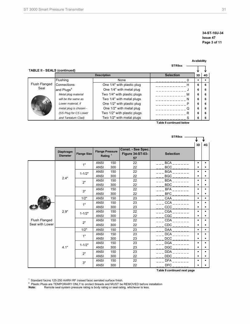
ST 3000 Smart Pressure Transmitter 31
34-ST-16U-34
Issue 47
Page 3 of 11
STR9xx
TABLE II - SEALS (continued)
3D 4G
_ _ _ _ _ _ _ _ _ _ _ 0 • •_ _ _ _ _ _ _ _ _ _ _ H 6 6
_ _ _ _ _ _ _ _ _ _ _ J 6 6
Metal plug material _ _ _ _ _ _ _ _ _ _ _ M 6 6
will be the same as _ _ _ _ _ _ _ _ _ _ _ N 6 6
_ _ _ _ _ _ _ _ _ _ _ P 6 6
metal plug is chosen - _ _ _ _ _ _ _ _ _ _ _ Q 6 6
(SS Plug for CS Lower _ _ _ _ _ _ _ _ _ _ _ R 6 6
and Tantalum Clad) _ _ _ _ _ _ _ _ _ _ _ S 6 6
Table II continued below
STR9xx
3D 4G
ANSI 150 22 _ _ _ BCA _ _ _ _ _ _ • •ANSI 300 22 _ _ _ BCC _ _ _ _ _ _ • •ANSI 150 22 _ _ _ BGA _ _ _ _ _ _ • •ANSI 300 22 _ _ _ BGC _ _ _ _ _ _ • •ANSI 150 22 _ _ _ BDA _ _ _ _ _ _ • •ANSI 300 22 _ _ _ BDC _ _ _ _ _ _ • •ANSI 150 22 _ _ _ BFA _ _ _ _ _ _ • •ANSI 300 22 _ _ _ BFC _ _ _ _ _ _ • •
1/2" ANSI 150 23 _ _ _ CAA _ _ _ _ _ _ • •ANSI 150 23 _ _ _ CCA _ _ _ _ _ _ • •ANSI 300 23 _ _ _ CCC _ _ _ _ _ _ • •ANSI 150 22 _ _ _ CGA _ _ _ _ _ _ • •ANSI 300 22 _ _ _ CGC _ _ _ _ _ _ • •ANSI 150 22 _ _ _ CDA _ _ _ _ _ _ • •ANSI 300 22 _ _ _ CDC _ _ _ _ _ _ • •
1/2" ANSI 150 23 _ _ _ DAA _ _ _ _ _ _ • •ANSI 150 23 _ _ _ DCA _ _ _ _ _ _ • •ANSI 300 23 _ _ _ DCC _ _ _ _ _ _ • •ANSI 150 23 _ _ _ DGA _ _ _ _ _ _ • •ANSI 300 23 _ _ _ DGC _ _ _ _ _ _ • •ANSI 150 23 _ _ _ DDA _ _ _ _ _ _ • •ANSI 300 22 _ _ _ DDC _ _ _ _ _ _ • •ANSI 150 22 _ _ _ DFA _ _ _ _ _ _ • •ANSI 300 22 _ _ _ DFC _ _ _ _ _ _ • •
Table II continued next page
1 Standard facing 125-250 AARH RF (raised face) serrated surface finish.4 Plastic Plugs are TEMPORARY ONLY to protect threads and MUST be REMOVED before installationNote: Remote seal system pressure rating is body rating or seal rating, whichever is less.
Connections
Flushing
and Plugs4
Flush Flanged
Seal
Lower material, if
2"
1"
1-1/2"
Flange Size
1-1/2"
Flush Flanged Seal with Lower
2.4"
4.1"
1"
2.9"
2"
3"
2"
3"
1"
Selection
One 1/4" with plastic plug
Availability
Selection
Diaphragm Diameter
None
One 1/2" with metal plug
Const. - See Spec. Figure 34-ST-03-
57
Flange Pressure
Rating 1
1-1/2"
One 1/4" with metal plug
Two 1/4" with plastic plugs
Description
Two 1/2" with plastic plugs
Two 1/2" with metal plugs
Two 1/4" with metal plugs
One 1/2" with plastic plug
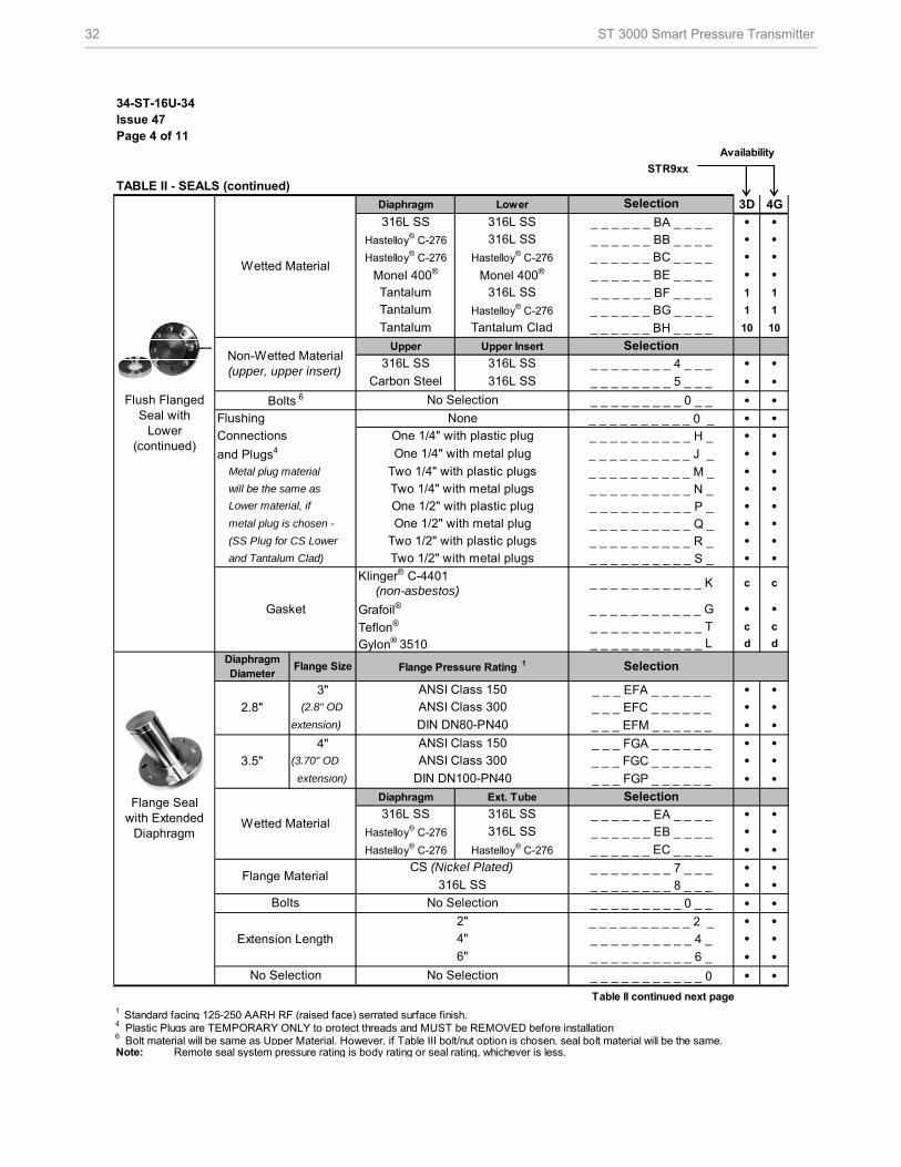
32 ST 3000 Smart Pressure Transmitter
34-ST-16U-34Issue 47Page 4 of 11
Availability
STR9xx
TABLE II - SEALS (continued)
Diaphragm Lower 3D 4G
_ _ _ _ _ _ BA _ _ _ _ • •_ _ _ _ _ _ BB _ _ _ _ • •_ _ _ _ _ _ BC _ _ _ _ • •_ _ _ _ _ _ BE _ _ _ _ • •_ _ _ _ _ _ BF _ _ _ _ 1 1
_ _ _ _ _ _ BG _ _ _ _ 1 1
_ _ _ _ _ _ BH _ _ _ _ 10 10
Upper Upper Insert
_ _ _ _ _ _ _ _ 4 _ _ _ • •_ _ _ _ _ _ _ _ 5 _ _ _ • •_ _ _ _ _ _ _ _ _ 0 _ _ • •_ _ _ _ _ _ _ _ _ _ 0 _ • •_ _ _ _ _ _ _ _ _ _ H _ • •_ _ _ _ _ _ _ _ _ _ J _ • •
Metal plug material _ _ _ _ _ _ _ _ _ _ M _ • • will be the same as _ _ _ _ _ _ _ _ _ _ N _ • •
_ _ _ _ _ _ _ _ _ _ P _ • • metal plug is chosen - _ _ _ _ _ _ _ _ _ _ Q _ • • (SS Plug for CS Lower _ _ _ _ _ _ _ _ _ _ R _ • • and Tantalum Clad) _ _ _ _ _ _ _ _ _ _ S _ • •
_ _ _ _ _ _ _ _ _ _ _ G • •_ _ _ _ _ _ _ _ _ _ _ T c c
_ _ _ _ _ _ _ _ _ _ _ L d d
3" _ _ _ EFA _ _ _ _ _ _ • •(2.8" OD _ _ _ EFC _ _ _ _ _ _ • •
extension) _ _ _ EFM _ _ _ _ _ _ • •4" _ _ _ FGA _ _ _ _ _ _ • •
(3.70" OD _ _ _ FGC _ _ _ _ _ _ • •extension) _ _ _ FGP _ _ _ _ _ _ • •
Diaphragm Ext. Tube
_ _ _ _ _ _ EA _ _ _ _ • •_ _ _ _ _ _ EB _ _ _ _ • •_ _ _ _ _ _ EC _ _ _ _ • •_ _ _ _ _ _ _ _ 7 _ _ _ • •_ _ _ _ _ _ _ _ 8 _ _ _ • •_ _ _ _ _ _ _ _ _ 0 _ _ • •_ _ _ _ _ _ _ _ _ _ 2 _ • •_ _ _ _ _ _ _ _ _ _ 4 _ • •_ _ _ _ _ _ _ _ _ _ 6 _ • •_ _ _ _ _ _ _ _ _ _ _ 0 • •
Table II continued next page1 Standard facing 125-250 AARH RF (raised face) serrated surface finish.4 Plastic Plugs are TEMPORARY ONLY to protect threads and MUST be REMOVED before installation6 Bolt material will be same as Upper Material. However, if Table III bolt/nut option is chosen, seal bolt material will be the same. Note: Remote seal system pressure rating is body rating or seal rating, whichever is less.
Selection
Flange Pressure Rating 1
Lower material, if
Diaphragm Diameter
Flange Size
Grafoil®
Teflon®
No Selection
Hastelloy® C-276
Tantalum
Tantalum
316L SS
ANSI Class 150
DIN DN80-PN40
Monel 400® Monel 400®
316L SS 316L SS
_ _ _ _ _ _ _ _ _ _ _ K
Selection
Selection
DIN DN100-PN40
ANSI Class 300
ANSI Class 150
Hastelloy® C-276
Selection
cc
Flange Seal with Extended
Diaphragm
2.8"
Wetted Material
Tantalum
316L SS
Hastelloy® C-276
Tantalum Clad
316L SS
316L SS
Non-Wetted Material (upper, upper insert)
Hastelloy® C-276
Bolts 6
Flushing
3.5"
Extension Length
Bolts
Flange Material
Two 1/2" with metal plugs
One 1/4" with plastic plug
None
Carbon Steel
One 1/2" with metal plug
One 1/2" with plastic plug
316L SS
No Selection
Klinger® C-4401
CS (Nickel Plated)
316L SS
No Selection
Two 1/2" with plastic plugs
316L SS
Wetted Material316L SS
Gasket
Two 1/4" with metal plugs
(non-asbestos)
ANSI Class 300
Hastelloy® C-276
and Plugs4
6"
2"
Hastelloy® C-276
4"
One 1/4" with metal plug
Two 1/4" with plastic plugs
Connections
Flush Flanged Seal with
Lower (continued)
316L SS
Gylon® 3510
Hastelloy® C-276
No Selection
ST 3000 Smart Pressure Transmitter 33
34-ST-16U-34
Issue 47
Page 5 of 11
Availability
STR9xx
TABLE II - SEALS (continued)
3.5" 3" _ _ _ GFA _ _ _ _ _ _ • •Diaphragm Body
_ _ _ _ _ _ GA _ _ _ _ • •_ _ _ _ _ _ GB _ _ _ _ • •_ _ _ _ _ _ GC _ _ _ _ • •_ _ _ _ _ _ GE _ _ _ _ • •_ _ _ _ _ _ GG _ _ _ _ 1 1
_ _ _ _ _ _ _ _ 0 _ _ _ • •_ _ _ _ _ _ _ _ _ 0 _ _ • •_ _ _ _ _ _ _ _ _ _ A _ • •_ _ _ _ _ _ _ _ _ _ B _ 5 5
_ _ _ _ _ _ _ _ _ _ C _ 5 5
_ _ _ _ _ _ _ _ _ _ D _ 5 5
_ _ _ _ _ _ _ _ _ _ _ 0 • •_ _ _ _ _ _ _ _ _ _ _ H 6 6
_ _ _ _ _ _ _ _ _ _ _ J 6 6
Metal plug material _ _ _ _ _ _ _ _ _ _ _ M 6 6
will be the same as _ _ _ _ _ _ _ _ _ _ _ N 6 6
_ _ _ _ _ _ _ _ _ _ _ P 6 6
metal plug is chosen - _ _ _ _ _ _ _ _ _ _ _ Q 6 6
(SS Plug for CS Lower _ _ _ _ _ _ _ _ _ _ _ R 6 6
and Tantalum Clad) _ _ _ _ _ _ _ _ _ _ _ S 6 6
Table II continued below
Availability
STR9xx
TABLE II - SEALS (continued)
Diaphragm Body
_ _ _ _ _ _ HA _ _ _ _ •_ _ _ _ _ _ HB _ _ _ _ •_ _ _ _ _ _ HC _ _ _ _ •
•_ _ _ _ _ _ _ _ _ 0 _ _ •_ _ _ _ _ _ _ _ _ _ 0 _ •_ _ _ _ _ _ _ _ _ _ _ 0 •Table II continued next page
1 Standard facing 125-250 AARH RF (raised face) serrated surface finish.4 Plastic Plugs are TEMPORARY ONLY to protect threads and MUST be REMOVED before installation7 Tantalum Body has Tantalum wetted parts and 316 SS non-wetted partsNote: Remote seal system pressure rating is body rating or seal rating, whichever is less.
Chemical Tee "Taylor" Wedge
750 psiTaylor
Wedge 5" O.D.
No Selection
Diaphragm Diameter
Diaphragm Diameter
Flange Size
Pancake Seal
Calibration Rings
Flushing
and Plugs4
Lower material, if
Flange Size
Non-Wetted Materials
No Selection
Wetted Material
Connections
3.5"
Tantalum
One 1/2" with plastic plug
One 1/4" with metal plug
Selection
Selection
Hastelloy® C-276
v
No Selection No Selection
Wetted Material
Bolts
316L SS
Styles No Selection
Hastelloy® C-276
No Selection
Monel 400®
Hastelloy® C-276
316L SS
Tantalum 7Monel 400®
Hastelloy® C-276
ANSI Class 150/300/600
316L SS
Hastelloy® C-276
316L SS
316L SS
316L SS
Two 1/4" with metal plugs
No Selection
Hastelloy® C-276
Non-Wetted Material No Selection
_ _ _ HM0 _ _ _ _ _ _
_ _ _ _ _ _ _ _ 0 _ _ _
Selection
4G3D
Selection
316L SS
Flange Pressure Rating Dependent on
Customer Flange 1
Hastelloy® C-276
None
Flange Pressure Rating 1
One 1/4" with plastic plug
Monel 400®
One 1/2" with metal plug
4G3D
None
Two 1/2" with metal plugs
Two 1/2" with plastic plugs
Two 1/4" with plastic plugs
34 ST 3000 Smart Pressure Transmitter
34-ST-16U-34Issue 47Page 6 of 11
AvailabilitySTR9xx
TABLE II - SEALS (continued)
_ _ _ JJG _ _ _ _ _ _ • •_ _ _ JKG _ _ _ _ _ _ • •_ _ _ JLG _ _ _ _ _ _ • •_ _ _ KJG _ _ _ _ _ _ • •_ _ _ KKG _ _ _ _ _ _ • •_ _ _ KLG _ _ _ _ _ _ • •_ _ _ LJG _ _ _ _ _ _ • •_ _ _ LKG _ _ _ _ _ _ • •_ _ _ LLG _ _ _ _ _ _ • •
Diaphragm Lower
_ _ _ _ _ _ JA _ _ _ _ • •_ _ _ _ _ _ JB _ _ _ _ • •_ _ _ _ _ _ JC _ _ _ _ • •_ _ _ _ _ _ JD _ _ _ _ • •_ _ _ _ _ _ JE _ _ _ _ • •_ _ _ _ _ _ JF _ _ _ _ 1 1
_ _ _ _ _ _ JG _ _ _ _ 1 1
_ _ _ _ _ _ _ _ A _ _ _ • •_ _ _ _ _ _ _ _ C _ _ _ w w
_ _ _ _ _ _ _ _ _ C _ _ 1 1
_ _ _ _ _ _ _ _ _ D _ _ • •_ _ _ _ _ _ _ _ _ _ 0 _ • •_ _ _ _ _ _ _ _ _ _ H _ • •_ _ _ _ _ _ _ _ _ _ J _ • •
Metal plug material _ _ _ _ _ _ _ _ _ _ M _ • • will be the same as _ _ _ _ _ _ _ _ _ _ N _ • •
_ _ _ _ _ _ _ _ _ _ P _ 11 11
metal plug is chosen - _ _ _ _ _ _ _ _ _ _ Q _ 11 11
(SS Plug for CS Lower _ _ _ _ _ _ _ _ _ _ R _ 11 11
and Tantalum Clad) _ _ _ _ _ _ _ _ _ _ S _ 11 11
_ _ _ _ _ _ _ _ _ _ _ G • •_ _ _ _ _ _ _ _ _ _ _ T c c
_ _ _ _ _ _ _ _ _ _ _ L d d
4 Plastic Plugs are TEMPORARY ONLY to protect threads and MUST be REMOVED before installation8 If Table III Bolt/Nut option is chosen, Seal bolts will ship as same material, and MAWP may change.Note: Remote seal system pressure rating is body rating or seal rating, whichever is less.
Gasket
Non-Wetted Material (upper)
2.9"
Two 1/4" with plastic plugsTwo 1/4" with metal plugs
4.1"1 NPT
1,500 psi
Bolts 8
316L SS
Monel 400®
Connections
Seal with Threaded Process
Connection
Flushing
and Plugs4
1 NPT
1/2 NPT
1/2 NPT
Wetted Material316L SS
One 1/4" with plastic plug
304 SS
316L SS
None
Hastelloy® C-276
Hastelloy® C-276
TantalumMonel 400®
Hastelloy® C-276
Tantalum
Hastelloy® C-276
Selection
Selection
750 psi
Carbon Steel
(non-asbestos)
Gylon® 3510
Lower material, if
Klinger® C-4401
Grafoil®
Teflon®
One 1/2" with plastic plug
Two 1/2" with metal plugsTwo 1/2" with plastic plugsOne 1/2" with metal plug
Diaphragm Diameter
One 1/4" with metal plug
316L SS
3/4 NPT
316L SS
1,250 psi
2,500 psi
Threaded Process Connection Size (NPT Female) 304 SS
BoltsC.S. Bolts
Seal Pressure Rating *
2.4"1/2 NPT
1,250 psi
1 NPT3/4 NPT
3/4 NPT
CS (Nickel Plated)Stainless SteelCarbon Steel
c_ _ _ _ _ _ _ _ _ _ _ K
3D 4G
c
2,500 psi
ST 3000 Smart Pressure Transmitter 35
34-ST-16U-34
Issue 47
Page 7 of 11
Availability
STR9xx
TABLE II - SEALS (continued)
1.9" 2" _ _ _ MD0 _ _ _ _ _ _ 25 24
2.4" 2-1/2" _ _ _ NE0 _ _ _ _ _ _ 24 24
2.9" 3" _ _ _ PF0 _ _ _ _ _ _ 24 24
4.1" 4" _ _ _ QG0 _ _ _ _ _ _ 24 24
Diaphragm Body
_ _ _ _ _ _ N A _ _ _ _ • •• •• •
_ _ _ _ _ _ _ _ _ 0 _ _ • •_ _ _ _ _ _ _ _ _ _ 8 _ • •_ _ _ _ _ _ _ _ _ _ _ 0 • •
Seal Pressure Rating * *
Diaphragm Lower Housing
_ _ _ _ _ _ RA _ _ _ _ • •_ _ _ _ _ _ RB _ _ _ _ • •_ _ _ _ _ _ RC _ _ _ _ • •_ _ _ _ _ _ RD _ _ _ _ • •_ _ _ _ _ _ SB _ _ _ _ • •_ _ _ _ _ _ SC _ _ _ _ • •
Body
Carbon Steel _ _ _ _ _ _ _ _ B _ _ _ 1 1
_ _ _ _ _ _ _ _ C _ _ _ • •_ _ _ _ _ _ _ _ _ 0 _ _ • •_ _ _ _ _ _ _ _ _ _ 0 _ • •
• •
_ _ _ _ _ _ _ _ _ _ _ G • •_ _ _ _ _ _ _ _ _ _ _ T • •_ _ _ _ _ _ _ _ _ _ _ L • •
8 If Table III Bolt/Nut option is chosen, Seal bolts will ship as same material, and MAWP may change.9 All sanitary seals have dairy grade 3A approval.10 Bolts are not included with "body only" selection.Note: Remote seal system pressure rating is body rating or seal rating, whichever is less.
No Selection
No Selection
_ _ _ RFK _ _ _ _ _ _
Selection
316L SS 304 SS
Styles
Bolts 8, 10
No Selection
Selection
Diaphragm Diameter
Diaphragm Diameter
Selection
Customer clamp rating or 600 psi, whichever is less
1,500 psifor 3" Pipe ≥
4" pipe
Wetted Material
Gasket
Bolts
316L SS
2.4" 8-Bolt Design
_ _ _ _ _ _ _ _ 0 _ _ _
Teflon®
Saddle Seal
Grafoil®Gasket
Sanitary Seal 9
Flange Size
Non-Wetted Material
Gylon® 3510
1,250 psi
No Selection
316L SS
• •
• •
Size and Bolt Pattern 304 SS Bolts
Pressure Rating
N/A-Body Only 10
_ _ _ RQK _ _ _ _ _ _
Selection
_ _ _ RGK _ _ _ _ _ _
No Selection
Tri-Clover Tri-Clamp®
Hastelloy® C-276
Klinger® C-4401 (non-asbestos)
N/A-Body Only 10
316L SS
1,500 psi
1,250 psi
Hastelloy® C-276
316L SS
Hastelloy® C-276
C.S. Bolts
316L SS Carbon Steel
Carbon Steel
Hastelloy® C-276
316L SS
316L SS
2.4" 6-Bolt Design
Styles
for 3" Pipe ≥ 4" pipe
No Selection
Non-Wetted Material
Wetted Material
•
• •
_ _ _ _ _ _ _ _ _ _ _ K
_ _ _ RPK _ _ _ _ _ _
•
Selection
3D 4G
36 ST 3000 Smart Pressure Transmitter
34-ST-16U-34
Issue 47Page 8 of 11 Availability
STR9xx
3D 4G
● ●● ●● ●● ●r r
• •• •m m
x x
s s
n n
• •• •• •• •• •• •• •
15 15
14 14
• •• •
15 15
21 21
• •• •
• •
• •
•••
j j
j
j j
j
● ●● ●● ●● ●● ●
• •h h
• •• •• •• •
22 22
o •16
• •• •2 2
Table III continued next page5 Supplied as 316 SS or as Grade CF8M, the casting equivalent of 316 SS.
TABLE III - OPTIONS Selection
Write Protection (Delivered in the "disabled" position)
Stainless Steel Customer Wired-On Tag (blank)
i i
b
b
b
b
b
b
SLLPCCTCFCWPWX
TG
TB
H6FF
MESM
A1
A2
A4A5
Gold Plated Seal Diaphragm (2 Seals)
A6A7A8NE
CR
SB
CILZZS
SH
SSB7
G1G2
SXFB
UM
N1N2
MBMX
F5FEF7F8
0XTPF1F3
FGFXMT
1/2 NPT Male to M20 Female 316 SS Certified Conduit Adapter (ATEX, CSA & IECEx)
1/2 NPT Male to 3/4 NPT Female 316 SS Certified Conduit Adapter (ATEX, CSA & IECEx)
M20 Male to 1/2 NPT Female 316 SS Certified Conduit Adaptor (ATEX, CSA & IECEx)
1/2 NPT Zinc-plated Certified Conduit Plug (ATEX, CSA & IECEx) 1/2 NPT 316 SS Certified Conduit Plug (ATEX, CSA & IECEx) M20 316 SS Certified Conduit Plug (ATEX, CSA & IECEx) 1/2 NPT Non-certified Conduit plug (Zinc-plated carbon steel, general use)
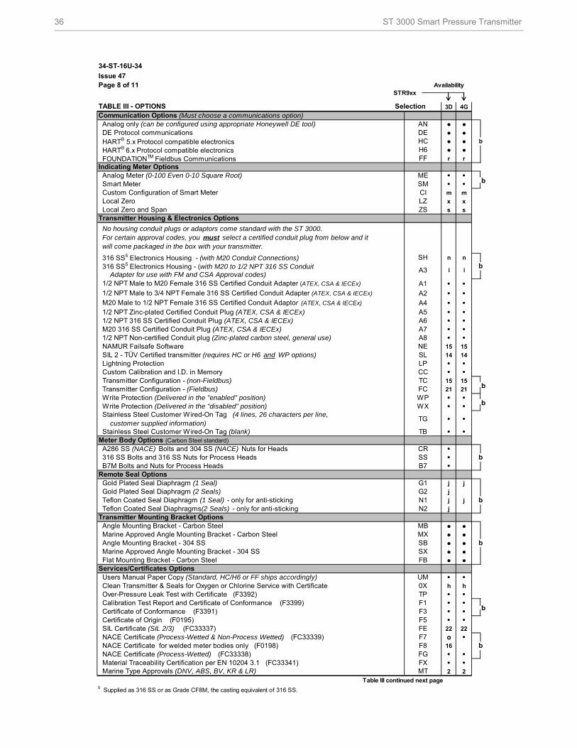
316 SS5 Electronics Housing - (with M20 Conduit Connections)
No housing conduit plugs or adaptors come standard with the ST 3000. For certain approval codes, you must select a certified conduit plug from below and it will come packaged in the box with your transmitter.
A3 Adapter for use with FM and CSA Approval codes) 316 SS5 Electronics Housing - (with M20 to 1/2 NPT 316 SS Conduit
FOUNDATIONTM Fieldbus Communications
Transmitter Housing & Electronics Options
Analog Meter (0-100 Even 0-10 Square Root) Smart Meter Custom Configuration of Smart Meter Local Zero Local Zero and Span
Analog only (can be configured using appropriate Honeywell DE tool) DE Protocol communications HART® 5.x Protocol compatible electronics HART® 6.x Protocol compatible electronics
ANDEHC
Communication Options (Must choose a communications option)
Stainless Steel Customer Wired-On Tag (4 lines, 26 characters per line, customer supplied information)
NAMUR Failsafe Software SIL 2 - TÜV Certified transmitter (requires HC or H6 and WP options) Lightning Protection Custom Calibration and I.D. in Memory Transmitter Configuration - (non-Fieldbus) Transmitter Configuration - (Fieldbus) Write Protection (Delivered in the "enabled" position)
Indicating Meter Options
Angle Mounting Bracket - Carbon Steel Marine Approved Angle Mounting Bracket - Carbon Steel
Certificate of Origin (F0195) SIL Certificate (SIL 2/3) (FC33337)
Clean Transmitter & Seals for Oxygen or Chlorine Service with Certificate Over-Pressure Leak Test with Certificate (F3392) Calibration Test Report and Certificate of Conformance (F3399) Certificate of Conformance (F3391)
Material Traceability Certification per EN 10204 3.1 (FC33341) Marine Type Approvals (DNV, ABS, BV, KR & LR)
NACE Certificate for welded meter bodies only (F0198)
Angle Mounting Bracket - 304 SS Marine Approved Angle Mounting Bracket - 304 SS Flat Mounting Bracket - Carbon Steel
Users Manual Paper Copy (Standard, HC/H6 or FF ships accordingly)Services/Certificates Options
NACE Certificate (Process-Wetted) (FC33338)
NACE Certificate (Process-Wetted & Non-Process Wetted) (FC33339)
Meter Body Options (Carbon Steel standard)
Remote Seal Options
Transmitter Mounting Bracket Options
A286 SS (NACE) Bolts and 304 SS (NACE) Nuts for Heads 316 SS Bolts and 316 SS Nuts for Process Heads B7M Bolts and Nuts for Process Heads
Gold Plated Seal Diaphragm (1 Seal)
Teflon Coated Seal Diaphragm (1 Seal) - only for anti-sticking Teflon Coated Seal Diaphragms(2 Seals) - only for anti-sticking
b
b
b
b
ST 3000 Smart Pressure Transmitter 37
34-ST-16U-34Issue 47Page 9 of 11
STR9xx
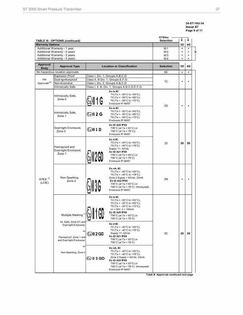
TABLE III - OPTIONS (continued)
3D 4G
W1 • •W2 • •W3 • •W4 • •
9X • •
Table III Approvals continued next page
Warranty Options
Intrinsically Safe, Zone 1
Ex ia IIC T4 (Ta = –50°C to +93°C); T5 (Ta = –50°C to +85°C); T6 (Ta = –50°C to +70°C)Enclosure IP 66/67
Intrinsically Safe, Zone 0
3C
Flameproof and Dust-tight Enclosure, Zone 1
ATEX 10
(LCIE)
Non-Sparking, Zone 2
Intrinsically Safe
Explosion Proof
• •
26
26 26
26
•
b
•
•
4G
No hazardous location approvals
•1CClass I, Div. 2, Groups A,B,C,D
FM
ApprovalsSM
Class I, Div. 1, Groups A,B,C,DDust-IgnitionproofNon-Incendive
Class II, III Div. 1, Groups E,F,G
Ex ia IIC T4 (Ta = –50°C to +93°C); T5 (Ta = –50°C to +85°C); T6 (Ta = –50°C to +70°C)Enclosure IP 66/67
3N
3S
Class I, II, III, Div. 1, Groups A,B,C,D,E,F,G
Ex d IIC T5 (Ta = –40°C to +93°C), T6 (Ta = –40°C to +78°C) Supply 11- 42VdcEx tD A21 IP6X T95°C (at Ta = 93°C) or T80°C (at Ta = 78°C)
3D
Additional Warranty - 3 years
Ex tD A20 IP6X T95°C (at Ta = 93°C) or T80°C (at Ta = 78°C))Enclosure IP 66/67
Ex nA, IIC T5 (Ta = –40°C to +93°C), T6 (Ta = –40°C to +78°C); Zone 2 Supply < 42Vdc, 23mAEx tD A22 IP6X T95°C (at Ta = 93°C) or T80°C (at Ta = 78°C) (Honeywell) Enclosure IP 66/67
Ex d IIC T5 (Ta = –40°C to +93°C), T6 (Ta = –40°C to +78°C)Supply 11- 42VdcEx tD A21 IP6X T95°C (at Ta = 93°C) or T80°C (at Ta = 78°C)Enclosure IP 66/67
Ex ia IIC T4 (Ta = –50°C to +93°C); T5 (Ta = –50°C to +85°C); T6 (Ta = –50°C to +70°C); Ui = 30V; Ii = 100mAEx tD A20 IP6X T95°C (at Ta = 93°C) or T80°C (at Ta = 78°C)
Dust-tight Enclosure, Zone 0
Ex nA, IIC T5 (Ta = –40°C to +93°C), T6 (Ta = –40°C to +78°C); Zone 2 Supply < 42Vdc, 23mA Ex tD A22 IP6X T95°C (at Ta = 93°C) or T80°C (at Ta = 78°C) (Honeywell).Enclosure IP 66/67
Additional Warranty - 2 years
Approval Body
SelectionLocation or ClassificationApproval Type
Additional Warranty - 4 years
Additional Warranty - 1 year
33
Multiple Marking 11
Int. Safe, Zone 0/1 and Dust-tight Enclosure,
or
Flameproof, Zone 1 and and Dust-tight Enclosure,
or
Non-Sparking, Zone 2
Selection
38 ST 3000 Smart Pressure Transmitter
34-ST-16U-34
Issue 47
Page 10 of 11
STR9xx
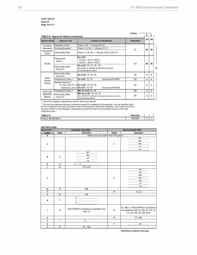
TABLE III - Approvals Options (continued)
3D 4G
● ●
● ●
● ●
10 See ATEX installation requirements in the ST 3000 User's Manual
TABLE IV
• •
RESTRICTIONSRestriction
Letter Table Table Selectionb
_ _ _ _ _ _ BF _ _ _ _,_ _ _ _ _ _ BG _ _ _ _,_ _ _ _ _ _ BH _ _ _ _,_ _ _ _ _ _ JF _ _ _ _,
_ _ _ _ _ _ JG _ _ _ _,
_ _ _ _ _ _ BF _ _ _ _,_ _ _ _ _ _ BG _ _ _ _,_ _ _ _ _ _ JF _ _ _ _,
_ _ _ _ _ _ JG _ _ _ _,
h I, II _ 2 _ - 2 _ _ _ _ _ _ _ _ _ _ _
i_ _ _ _ _ _ AF _ _ _ __ _ _ _ _ _ BF _ _ _ __ _ _ _ _ _ BG _ _ _ __ _ _ _ _ _ BH _ _ _ __ _ _ _ _ _ GG _ _ _ __ _ _ _ _ _ JF _ _ _ __ _ _ _ _ _ JG _ _ _ _
mn 1C, 2Jo CR
0 _ _ _ _ _ _ _ _ _ _ _ _,2 _ _ _ _ _ _ _ _ _ _ _ _,4 _ _ _ _ _ _ _ _ _ _ _ _
r
s FF, ME
v 2 _ _
w _ _ _ _ _ _ JA _ _ _ _
x FF, SM
Restrictions continued next page
III
Flameproof, Zone 1
6S
ZA
II
Select only one option from this group
6D
d
c
III
II
26
SelectionApproval Body
●
26
2J
26CA
Z2
26
Canadian Standards
Association (CSA)
IECEx
Flameproof, Zone 1
Flameproof, Zone 1
CERTUSP INMETRO
(Brazil)
Intrinsically Safe, Zone 0/1
Intrinsically Safe, Zone 0/1
SAEx (South Africa)
III
Intrinsically Safe, Zone 0/1
BR- Ex ia IIC; T4, T5, T6(See CERTUSP certificate for detailed temperature codes by Communications option)
II
1C or 2J
Not Available With
Ex ia IIC T4, T5, T6 Ex d IIC T5, T6 Enclosure IP 66/67
Flameproof, Zone 1
Available Only With
Dust-Ignitionproof
Approval Type
certification types.
X X X X
III
III
III
SM
Explosion Proof
II
III
Intrinsically Safe
Ex ia IIC T4, T5, T6
Class I, II, III, Div. 1, Groups A,B,C,D,E,F,G
FISCO/FNICO compliance available only with 1C
I
II
Multiple Marking 11
Factory Identification
Int. Safe, Zone 0/1, or
11 The user must determine the type of protection required for installation of the equipment. The user shall then check
q
III
Selection
●
Ex ia IIC; T3, T4, T5 , T6 See Spec for detailed temperature codes by Communications option
Ex d IIC T5, T6 Enclosure IP 66/67
j
b
●
●
TC, ME or FISCO/FNICO compliance not available with 3C, 3N, 33, 3S, 2J,
CA, Z2, ZD, ZA, 6D & 6S
the box [√] adjacent to the type of protection used on the equipment certification nameplate. Once a type of protection has been checked on the nameplate, subsequently the equipment shall not be reinstalled using any of the other
BR- Ex d IIC T5, T6
Class I, Div. 1, Groups B,C,D
Ex d IIC; T5 (Ta = -40 to +93ºC), T6 (Ta = -40 to +78ºC)
ZD
Class II, III, Div. 1, Groups E,F,G
Location or Classification
Selection

ST 3000 Smart Pressure Transmitter 39
34-ST-16U-34Issue 47Page 11 of 11
RESTRICTIONS - (continued)
Table Table Selection
z _ _ D1 F7
MX, SX3
5 _ _ _ _ _ _ _ _ _ _ _ 06 _ _ _ _ _ _ _ _ _ _ A _
1 _ _, 3 _ _
8
_ _ _ _ _ _ _ _ _ _ _ TF7
_ _ _ _ _ _JJG_ _ _ _ _ _ _ _ _JKG_ _ _ _ _ _ _ _ _JLG_ _ _ _ _ _ _ _ _CAA_ _ _ _ _ _ _ _ _CCA_ _ _ _ _ _ _ _ _CCC_ _ _
1415 FF16
22
FM ApprovalsSM is a service mark of FM Global
Hastelloy® is a registered trademark of Haynes International
Monel 400® is a registered trademark of Special Metals Corporation.
HART® is a registered trademark of HART Communication Foundation.
FOUNDATIONTM Fieldbus is a registered trademark of Fieldbus Foundation.
Teflon® is a registered trademark of DuPont.
Neobee® is a registered trademark of Stepan Company.
Syltherm® 800 is a Trademark of Dow Corning Corporation
Klingersil® C-4401 is a registered trademark of THERMOSEAL, INC
GRAFOIL® is a registered trademarks of GrafTech International Holdings Inc
Gylon® 3510 is registered trademark of Garlock Sealing Technologies
Tri-Clover Tri-Clamp® is a registered trademark of Alfa-Laval
DC® 200 and DC® 704 are registered trademarks of Dow Corning
25 II_ A _ _ _ _ _ _ _ _ _ _ , _G _ _ _ _ _ _ _ _ _ _ , _2 _ _ _ _ _ _ _ _ _ _
24 III I & II
_ 2 _ _ _ _ _ _ _ _ _ _
Selection
II
III
IIIII
III
21 III FF
SL
_ _ _ _ _ _ AB2_ _ _
I
II
11
10
5 _ _
Restriction Letter
Available Only With
I
II
III
II
9
7
y
III
_ _ C
FF
2 _ _ - _ 2 _ _ _ _ _ _ _ _ _ _
III HC or H6 and WP III
26 III
_ _ _ _ _ _ AA2_ _ _
I
I
2
_ _ _ _ _ _ _ _ _ _ 0 _
II
III
III
CR
FB, MB, SB
I 2 _ _
Not Available With
II
CC, G1, G2, N1, N2, 0X, TP, MT, F1, TC, FC
MB, SB, FBIII
III
This approval code requires the selection of a certified conduit plug:
A5, A6 or A7
40 ST 3000 Smart Pressure Transmitter
For More Information
Learn more about how Honeywell’s ST 3000 Series
900 Remote Seal Transmitters can increase
performance, reduce downtime and decrease
configuration costs, visit our website
www.honeywellprocess.com/ or contact
your Honeywell account manager.
Honeywell Process Solutions
1860 West Rose Garden Lane
Phoenix, Arizona 85027
1-800-423-9883 or 1-800-343-0228
www.honeywellprocess.com/
Sales and Service For application assistance, current specifications, pricing, or name of the nearest Authorized Distributor, contact one of the offices below.
ASIA PACIFIC (TAC) [email protected]
Australia Honeywell Limited Phone: +(61) 7-3846 1255 FAX: +(61) 7-3840 6481 Toll Free 1300-36-39-36 Toll Free Fax: 1300-36-04-70 China – PRC - Shanghai Honeywell China Inc. Phone: (86-21) 5257-4568 Fax: (86-21) 6237-2826 Singapore Honeywell Pte Ltd. Phone: +(65) 6580 3278 Fax: +(65) 6445-3033 South Korea Honeywell Korea Co Ltd Phone: +(822) 799 6114 Fax: +(822) 792 9015
EMEA Phone: + 80012026455 or +44 (0)1202645583
FAX: +44 (0) 1344 655554
Email: (Sales) [email protected] or
(TAC) [email protected]
NORTH AMERICA Honeywell Process Solutions,
Phone: 1-800-423-9883
Or 1-800-343-0228
Email: (Sales) [email protected] or
(TAC) [email protected]
SOUTH AMERICA Honeywell do Brazil & Cia
Phone: +(55-11) 7266-1900
FAX: +(55-11) 7266-1905
Email: (Sales) [email protected] or (TAC) [email protected]
Specifications are subject to change without notice.
34-ST-03-57 March 2013 © 2013 Honeywell International Inc.