st3000 series 900 smart transmitter remote-sealed type of
TRANSCRIPT
No. SS2-STJ300-0100 (Rev.5)
ST3000 Series 900 Smart TransmitterRemote-sealed type of
Differential Pressure TransmittersModel STE929 / STE930
Specifications are subject to change without notice. - 1 - First issue: Apr. 1999 Rev.4: Oct. 2003
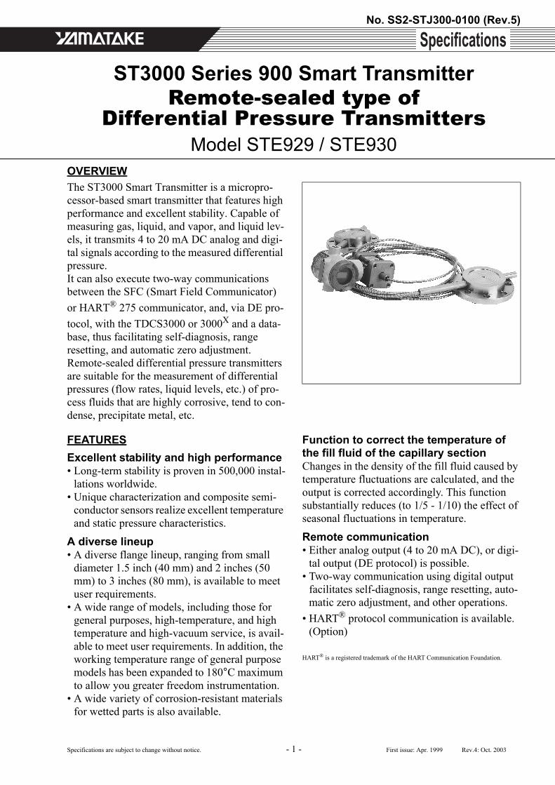
OVERVIEWThe ST3000 Smart Transmitter is a micropro-cessor-based smart transmitter that features high performance and excellent stability. Capable of measuring gas, liquid, and vapor, and liquid lev-els, it transmits 4 to 20 mA DC analog and digi-tal signals according to the measured differential pressure.It can also execute two-way communications between the SFC (Smart Field Communicator) or HART® 275 communicator, and, via DE pro-tocol, with the TDCS3000 or 3000X and a data-base, thus facilitating self-diagnosis, range resetting, and automatic zero adjustment.Remote-sealed differential pressure transmitters are suitable for the measurement of differential pressures (flow rates, liquid levels, etc.) of pro-cess fluids that are highly corrosive, tend to con-dense, precipitate metal, etc.
FEATURESExcellent stability and high performance• Long-term stability is proven in 500,000 instal-
lations worldwide.• Unique characterization and composite semi-
conductor sensors realize excellent temperature and static pressure characteristics.
A diverse lineup• A diverse flange lineup, ranging from small
diameter 1.5 inch (40 mm) and 2 inches (50 mm) to 3 inches (80 mm), is available to meet user requirements.
• A wide range of models, including those for general purposes, high-temperature, and high temperature and high-vacuum service, is avail-able to meet user requirements. In addition, the working temperature range of general purpose models has been expanded to 180°C maximum to allow you greater freedom instrumentation.
• A wide variety of corrosion-resistant materials for wetted parts is also available.
Function to correct the temperature of the fill fluid of the capillary sectionChanges in the density of the fill fluid caused by temperature fluctuations are calculated, and the output is corrected accordingly. This function substantially reduces (to 1/5 - 1/10) the effect of seasonal fluctuations in temperature.
Remote communication• Either analog output (4 to 20 mA DC), or digi-
tal output (DE protocol) is possible.• Two-way communication using digital output
facilitates self-diagnosis, range resetting, auto-matic zero adjustment, and other operations.
• HART® protocol communication is available. (Option)
HART® is a registered trademark of the HART Communication Foundation.

No. SS2-STJ300-0100 (Rev.5) Yamatake Corporation
- 2 -
APPLICATIONPetroleum / Petrochemical / Chemical• For the measurement of liquid levels including corrosive
fluids at high temperatures, and high temperatures under vacuum
• For the control of flow rates as used with tapless venturi tubes
• For replacement of displacement type level gauges• For materialization of instrumentation without connect-
ing tubes
Electric power / City gas / Other utilitiesFor measurement applications that require high degrees of stability and accuracy.
Pulp and paper• For lines that need transmitters resistant to chemical liq-
uids, corrosive fluids and the like• For the measurement of liquid levels in small tanks• Iron and Steel / Nonferrous metal / Ceramics• For lines that require stable measurement under strictly
controlled (temperature, humidity, etc.) conditions
Iron and steel / Nonferrous metal / CeramicsFor lines that require stable measurement under strictly controlled (temperature, humidity, vibration, etc.) condi-tions.
Machinery / ShipbuildingFor lines that require stable measurement under strictly controlled (temperature, humidity, etc.) conditions.
FUNCTIONAL SPECIFICATIONSType of protectionJIS C0920 watertight: NEMA3 and 4XJIS F8001 class 2 watertight: IEC IP67
FM Explosionproof approvalExplosionproof for Class I (Gas, steam), Division 1, Group A, B, C, DDust-ignition for Class II (Inflammable dust), Divi-sion 1, Group E, F, GSuitable for Class III (inflammable fiber), Division 1Nonincendive for Class I, Division 2, Group A, B, C, D
FM Intrinsically safe approvalIntrinsically safe for Class I, II, III, Division 1, Group A, B, C, D, E, F, G
ATEX Flameproof approvalCertificate number: INERIS99ATEX0010 X
II 2 GD EExd IIC T6 at -20 < Tamb < +60°C
ATEX Intrinsic safetyCertificate number: KEMA03ATEX1225 X
II 1 G EEx ia IIC T4 at -20 < Tamb < +60°CElectrical data: Ui = 30V
Ii = 100 mAPi = 1WCi = 3 nFLi = 0.5 mH
SPECIAL CONDITIONS FOR SAFE USE (X)Because the enclosure of the Smart Pressure Transmit-ter is made of aluminium, if it is mounted in an area where the use of category 1 G apparatus is required, it must be installed such, that, even in the event of rare incidents, ignition sources due to impact and friction sparks are excluded.
NEPSI Flameproof approvalEx d II T6 (with NEPSI Dust Ignition DIP DT T13)
NEPSI Intrinsically safe approvalEx ia IIC T5 at -20 < Tamb < +60°CEx ia IIC T6 at -20 < Tamb < +40°C
CSA Explosion-proof ApprovalCSA Explosion-proof for Class I, (Division 1), Groups A, B, C and DCSA Flameproof for Class I, Zone 1, Ex d IIC T6 at ambient temp. = -20°C to +60°CCSA Dust-ignitionproof for Class II and III, (Divi-sion 1), Groups E, F and G
EMC Conformity89/336/EEC, 92/31/EEC, 93/68/EEC Electromagnetic Compatibility (EMC) Directive
PED Conformity (97/23/EC)Comply with Module H (with “H1” option), or SEP (Sound Engineering Practice) for models of which maximum working pressure is 200 bar or lower.
Yamatake Corporation No. SS2-STJ300-0100 (Rev.5)
- 3 -
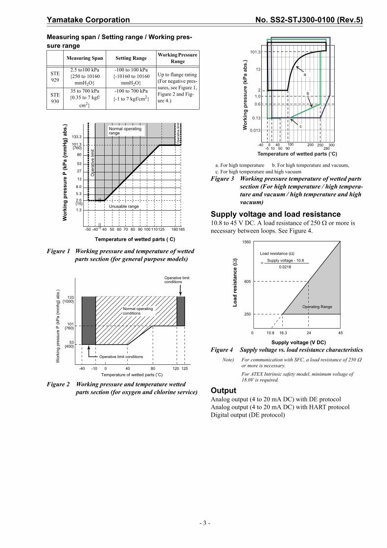
Measuring span / Setting range / Working pres-sure range
Figure 1 Working pressure and temperature of wetted parts section (for general purpose models)
Figure 2 Working pressure and temperature wetted parts section (for oxygen and chlorine service)
a. For high temperature b. For high temperature and vacuum, c. For high temperature and high vacuum
Figure 3 Working pressure temperature of wetted parts section (For high temperature / high tempera-ture and vacuum / high temperature and high vacuum)
Supply voltage and load resistance10.8 to 45 V DC. A load resistance of 250 Ω or more is necessary between loops. See Figure 4.
Figure 4 Supply voltage vs. load resistance characteristicsNote) For communication with SFC, a load resistance of 250 Ω
or more is necessary.For ATEX Intrinsic safety model, minimum voltage of 18.0V is required.
OutputAnalog output (4 to 20 mA DC) with DE protocolAnalog output (4 to 20 mA DC) with HART protocolDigital output (DE protocol)
Measuring Span Setting Range Working Pressure Range
STE 929
2.5 to100 kPa250 to 10160
mmH2O
-100 to 100 kPa-10160 to 10160
mmH2OUp to flange rating (For negative pres-sures, see Figure 1, Figure 2 and Fig-ure 4.)
STE 930
35 to 700 kPa0.35 to 7 kgf/
cm2
-100 to 700 kPa-1 to 7 kgf/cm2
133.3
101.3
80
53
27
13
8.0
5.3
2.0
760
151.3
Wor
king
pre
ssur
e P
(kPa
mm
Hg
abs
.)
Temperature of wetted parts ( C)
-50 -40 40 50 60 70 80 90 100 110125 180185
Ope
rativ
e lim
it
Normal operating range
Ope
rativ
e lim
it
Unusable range
1331000
101760
53400
-40 -10 0 40 80 120 125
Wor
king
pre
ssur
e P
(kP
a m
mhg
abs
.)
Temperature of wetted parts ( C)
Normal operatingconditions
Operative limit conditions
Operative limit conditions
-40 0 40 100 200 300-5 50 90 280
a
b
c
10250
13
2
101.3
1.0
0.6
0.13
0.013
Temperature of wetted parts ( C)
Wor
king
pre
ssur
e (k
Pa a
bs.)
605
1560
Load resistance (Ω)
Supply voltage - 10.8
0.0218
250
0 10.8 16.3 24 45
Load
resi
stan
ce (Ω
)
Supply voltage (V DC)
Operating Range
=

No. SS2-STJ300-0100 (Rev.5) Yamatake Corporation
- 4 -
Ambient temperature limits / Tempera-ture ranges of wetted parts
Note) *1: See the working pressures and temperatures of the wetted parts section in Figure 1, Figure 2 and Figure 4.
*2: Ambient temperatures of the transmitter itself*3: Approximate values at the temperature of 25°C*4: Note that if the operating temperature falls below the lower
limit of the normal operating range, the response of the transmitter becomes slower.
*5: When the wetted parts material is tantalum, the upper limit is 180°C.
*6: When the wetted parts material is tantalum, the upper limit is 200°C.
For Explosion proof models with digital indicators, which have to be used within the following ranges
Normal operating condition-20 to 70°C
Operative limit-30 to 80°C
Figure 5 Ambient temperature and tempera-ture of wetted parts section (for gen-eral purpose models)
[Flange diameter: Flush diaphragm 2 inches (50 mm) / 1.5 inch (40 mm)Extended diaphragm 3 inches (80 mm) / 2 inches (50 mm)]
Note) When the fill liquid is for general purposes, make sure before using your transmitter that the conditions in both Figure 1, Figure 5 and Figure 6 are met.
Figure 6 Ambient temperature and tempera-ture of wetted parts section (for gen-eral purpose models)
[Flange diameter: Flush diaphragm 3 inches (80 mm)Extended diaphragm 4 inches (100 mm)]
Figure 7 Ambient temperature and tempera-ture of wetted parts section (for high temperature and vacuum 2, 3 m)
[Flange diameter: Flush diaphragm 2 inches (50 mm) / 1.5 inch (40 mm)]
Temperature range (°C) *1, *4
Gen
eral
pu
rpos
e m
odel
Hig
h-te
mpe
ratu
re m
odel
Hig
h-te
mpe
ratu
re
vacu
um m
odel
s
Hig
h-te
mpe
ratu
rehi
gh-v
acuu
m m
odel
s
Oxy
gen
and
chlo
rine
mod
els
Wetted parts section
Normal operat-ing range
-40 to 180
-5 to 280 *5
-5 to 280 *5
10 to 300 *5
-10 to 120
Opera-tive limit range
-50 to 185
-10 to 310 *6
-10 to 310 *6
-10 to 310 *6
-40 to 125
Ambient temperature *2Flange size:Flush diaphragm type 3 inches (80 mm)Extended diaphragm type 4 inches (100 mm)
Normal operat-ing range
-30 to 75
-5 to 55
-5 to 55
10 to 55
-10 to 75
Opera-tive limit range
-50 to 80
-10 to 60
-10 to 60
-10 to 60
-40 to 80
Ambient temperature Note 2Flange size:Flush diaphragm type2 inches (50 mm) / 1.5 inch (40 mm)Extended diaphragm type 3 inches (80 mm) / 2 inches (50 mm)
Normal operat-ing range
-15 to 65
-5 to 45
-5 to 55
10 to 55
-10 to 75
Opera-tive limit range
-30 to 80
-10 to 55
-10 to 60
-10 to 60
-40 to 80
Specific gravity of fill fluid *3 0.935 1.07 1.07 1.09 1.87
Normal operatingrange
Am
bien
t tem
pera
ture
( C
)
Temperature of wetted parts ( C)
Operative limit range100
8075726850
-50 -40 100 110 150 180185 200
Am
bien
t tem
pera
ture
( C
)
Temperature of wetted parts ( C)
100
80
-50 -40 100 110 150 180185 200
Normal operatingrange
Operative limit range
615850
65
Am
bien
t tem
pera
ture
( C
)
Temperature of wetted parts ( C)
60
-10-5 165180 280 310
3327
55
-5-10
Normal operatingrange
Operative limit range
Yamatake Corporation No. SS2-STJ300-0100 (Rev.5)
- 5 -
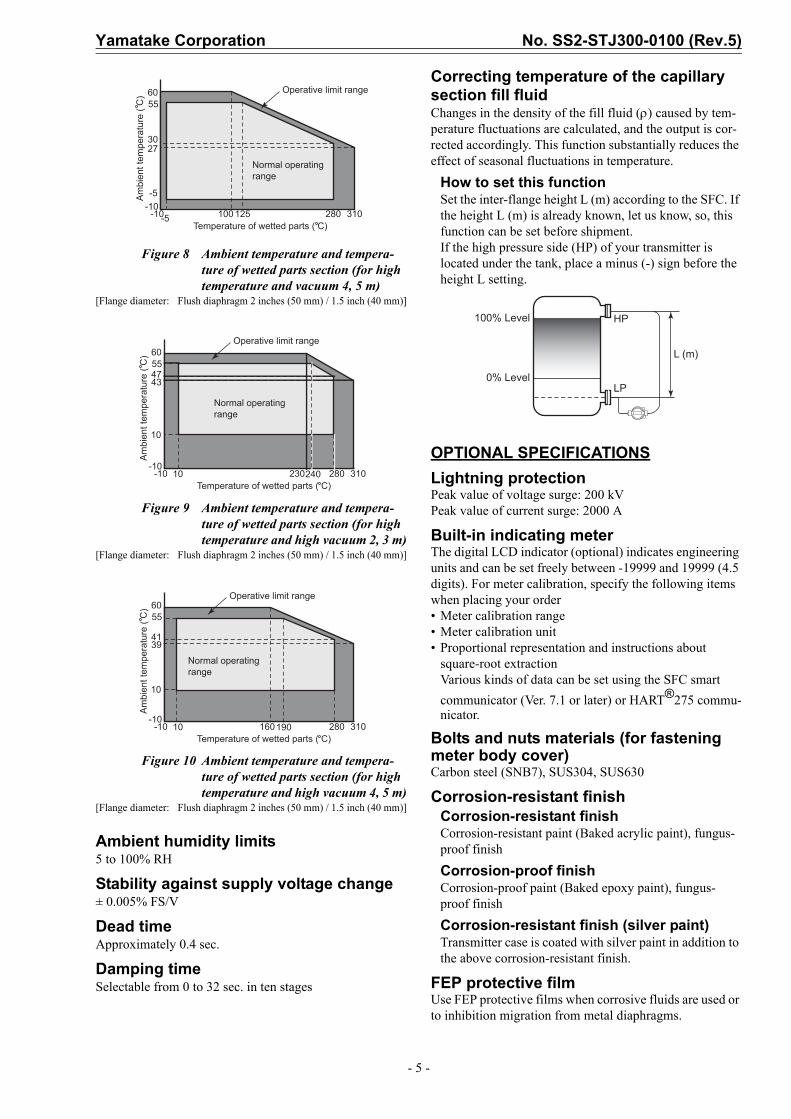
Figure 8 Ambient temperature and tempera-ture of wetted parts section (for high temperature and vacuum 4, 5 m)
[Flange diameter: Flush diaphragm 2 inches (50 mm) / 1.5 inch (40 mm)]
Figure 9 Ambient temperature and tempera-ture of wetted parts section (for high temperature and high vacuum 2, 3 m)
[Flange diameter: Flush diaphragm 2 inches (50 mm) / 1.5 inch (40 mm)]
Figure 10 Ambient temperature and tempera-ture of wetted parts section (for high temperature and high vacuum 4, 5 m)
[Flange diameter: Flush diaphragm 2 inches (50 mm) / 1.5 inch (40 mm)]
Ambient humidity limits5 to 100% RH
Stability against supply voltage change± 0.005% FS/V
Dead time Approximately 0.4 sec.
Damping timeSelectable from 0 to 32 sec. in ten stages
Correcting temperature of the capillary section fill fluidChanges in the density of the fill fluid (ρ) caused by tem-perature fluctuations are calculated, and the output is cor-rected accordingly. This function substantially reduces the effect of seasonal fluctuations in temperature.
How to set this functionSet the inter-flange height L (m) according to the SFC. If the height L (m) is already known, let us know, so, this function can be set before shipment.If the high pressure side (HP) of your transmitter is located under the tank, place a minus (-) sign before the height L setting.
OPTIONAL SPECIFICATIONSLightning protectionPeak value of voltage surge: 200 kVPeak value of current surge: 2000 A
Built-in indicating meterThe digital LCD indicator (optional) indicates engineering units and can be set freely between -19999 and 19999 (4.5 digits). For meter calibration, specify the following items when placing your order• Meter calibration range• Meter calibration unit• Proportional representation and instructions about
square-root extractionVarious kinds of data can be set using the SFC smart communicator (Ver. 7.1 or later) or HART®275 commu-nicator.
Bolts and nuts materials (for fastening meter body cover)Carbon steel (SNB7), SUS304, SUS630
Corrosion-resistant finishCorrosion-resistant finishCorrosion-resistant paint (Baked acrylic paint), fungus-proof finish
Corrosion-proof finishCorrosion-proof paint (Baked epoxy paint), fungus-proof finish
Corrosion-resistant finish (silver paint) Transmitter case is coated with silver paint in addition to the above corrosion-resistant finish.
FEP protective filmUse FEP protective films when corrosive fluids are used or to inhibition migration from metal diaphragms.
Am
bien
t tem
pera
ture
( C
)
Temperature of wetted parts ( C)
60
-10-5 100 125 280 310
3027
55
-5-10
Normal operatingrange
Operative limit range
Am
bien
t tem
pera
ture
( C
)
Temperature of wetted parts ( C)
60
-10 10 230240 280 310
4743
55
10
-10
Normal operatingrange
Operative limit range
Am
bien
t tem
pera
ture
( C
)
Temperature of wetted parts ( C)
60
-10 10 160190 280 310
4139
55
10
-10
Normal operatingrange
Operative limit range
100% Level
0% Level
HP
LP
L (m)
No. SS2-STJ300-0100 (Rev.5) Yamatake Corporation
- 6 -
Working temperature range0 to 110°C
Working pressure rangeAtmospheric pressure to flange rating(up to JIS10K, ANSI / JPI 150)(Not usable under negative pressure)
Oil free finishThe transmitter is shipped with oil-free wetted parts.
External zero/span adjustment functionThe transmitter can be easily zero/span adjusted in the field.
Burnout featureChoice of three states at abnormal conditionBurnout of output values: None, upper limit, lower limit
ElbowThis is an adaptor for changing the electrical conduit con-nection port from the horizontal to the vertical direction, if required by wiring conditions in the field. One or two elbows may be used as needed.
Conformance to SI unitsWe deliver transmitters set to any SI units as specified.
PHYSICAL SPECIFICATIONSMaterials
Fill fluidSilicone oil for general purpose and high-temperature vacuum modelsFluorine oil for oxygen and chlorine modelsFor specific gravity, refer to “Ambient temperature lim-its / Temperature ranges of wetted parts” on page 4.
Center bodySUS316
Transmitter caseAluminum alloy
Meter body coverSCS14A (SUS316L for diaphragm only)Hastelloy C, Tantalum, SUS316L
For wetted partsSCS14A (SUS316L for diaphragm only)Hastelloy C, Tantalum, SUS316L
Flange materialsCarbon steel (SF440A), SUS304, SUS316, SUS316L
Capillary sectionCapillary tube length2, 3, 4, 5, 6, 7, 8, 9 and 10 m2, 3, 4 and 5 m when flange diameter is flush diaphragm2 inches (50 mm) / 1.5 inch (40 mm) extended diaphragm3 inches (80 mm) / 2 inches (50 mm)
Capillary tube materialSUS316
Armored tube materialSUS304
Coating (optional)Olefin coating to improve corrosion resistance(Not applicable for high-temperature / Vacuum service type and High-temperature / High-vacuum service type.)
FinishBaked acrylic paintHousing light beige (Munsell 4Y7.2/1.3)Cap dark beige (Munsell 10YR4.7/0.5)
WeightApprox. 19.8 kg(Including JIS10K-80A flange and capillary 5 m long)
INSTALLATIONElectrical connection1/2NPT internal thread
GroundingResistance 100 Ω max.
MountingDirect mounting on the process side
Using 2-inch pipe mounting brackets: Mount the trans-mitter on a horizontal or vertical 2-inch pipe.
BracketCarbon steel
U-bolt and nutsSUS304
Process connectionFlange (both higher and lower pressure sides)
Flush diaphragmJIS 10K, 20K and 30K: 80 / 50 / 40 mm (RF) equivalentANSI 150, 300 and 600: 3 / 2 / 1.5 inches (RF) equivalentsJPI 150, 300 and 600: 3 / 2 / 1.5 inches (RF) equivalents
Extended diaphragmJIS 10K, 20K and 30K:100 / 80 / 50 mm (RF) equivalentsANSI 150 and 300: 4 / 3 / 2 inches (RF) equivalentsJPI 150 and 300: 4 / 3 / 2 inches (RF) equivalents
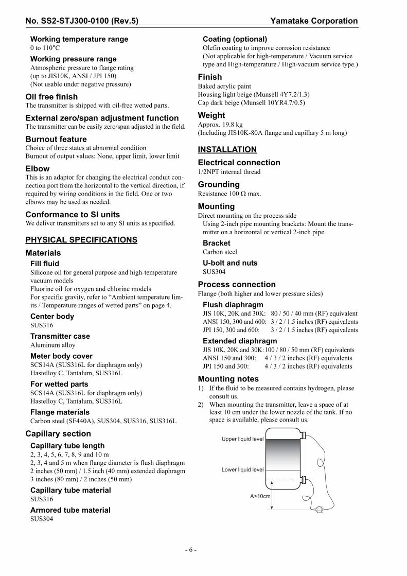
Mounting notes1) If the fluid to be measured contains hydrogen, please
consult us.2) When mounting the transmitter, leave a space of at
least 10 cm under the lower nozzle of the tank. If no space is available, please consult us.
Upper liquid level
Lower liquid level
A>10cm

Yamatake Corporation No. SS2-STJ300-0100 (Rev.5)
- 7 -
PERFORMANCE SPECIFICATIONSMax working pressureNote 1. Max. working pressure depends on flange rating, flange materials and operating temperature. Please refer to
the following data. Operating range of temperature depends on specification of transmitters.2. Max. working pressure depends on the smaller value of either 1.5 MPa or following data.3. Max. working pressure depends on the smaller value of either 10 MPa or following data.
JIS JPI/ANSICarbon steel
SUS304
SUS316
SUS316L
12.0
10.0
8.0
6.0
4.0
2.0
0.0Max
. Wor
king
Pre
ssur
e (M
Pa)
63K
40K30K
20K
10K
12.0
10.0
8.0
6.0
4.0
2.0
0.0Max
. Wor
king
Pre
ssur
e (M
Pa)
600#
300#
150#
12.0
10.0
8.0
6.0
4.0
2.0
0.0Max
. Wor
king
Pre
ssur
e (M
Pa)
63K
40K30K20K10K
12.0
10.0
8.0
6.0
4.0
2.0
0.0Max
. Wor
king
Pre
ssur
e (M
Pa)
600#
300#
150#
12.0
10.0
8.0
6.0
4.0
2.0
0.0Max
. Wor
king
Pre
ssur
e (M
Pa)
63K
40K30K20K10K
12.0
10.0
8.0
6.0
4.0
2.0
0.0Max
. Wor
king
Pre
ssur
e (M
Pa)
600#
300#
150#
12.0
10.0
8.0
6.0
4.0
2.0
0.0Max
. Wor
king
Pre
ssur
e (M
Pa)
63K40K30K20K10K
12.0
10.0
8.0
6.0
4.0
2.0
0.0Max
. Wor
king
Pre
ssur
e (M
Pa)
600#
300#150#

No. SS2-STJ300-0100 (Rev.5) Yamatake Corporation
- 8 -
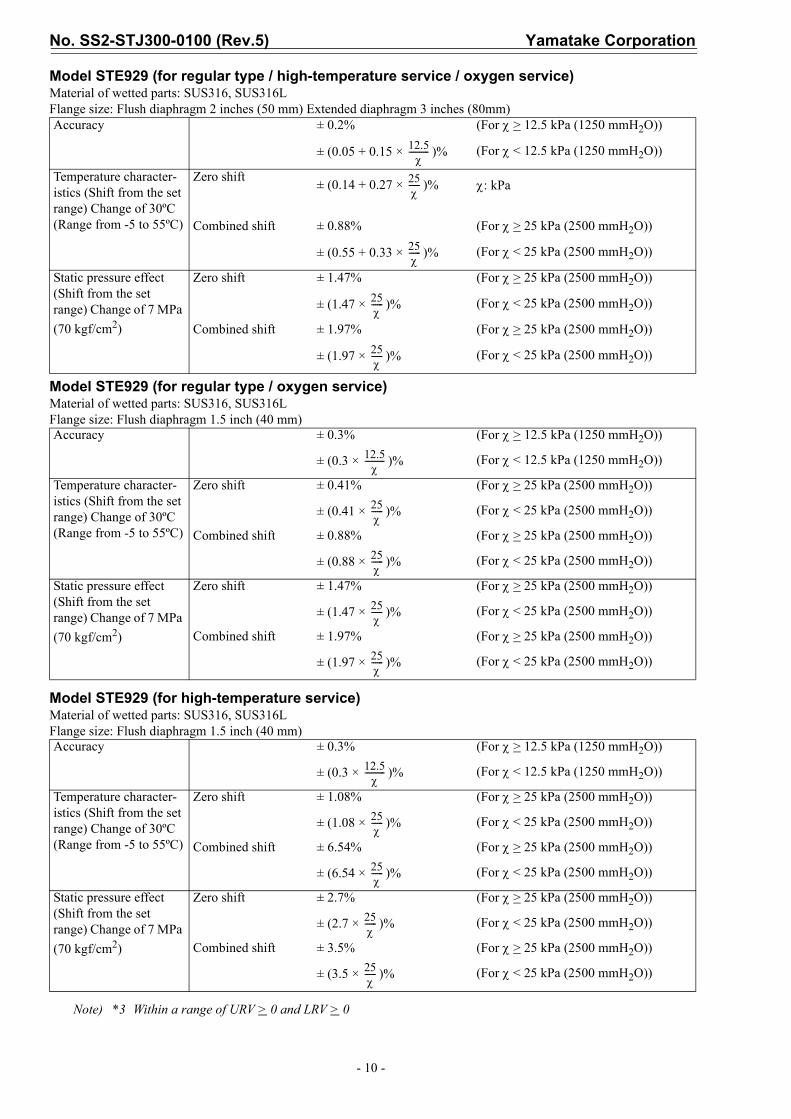
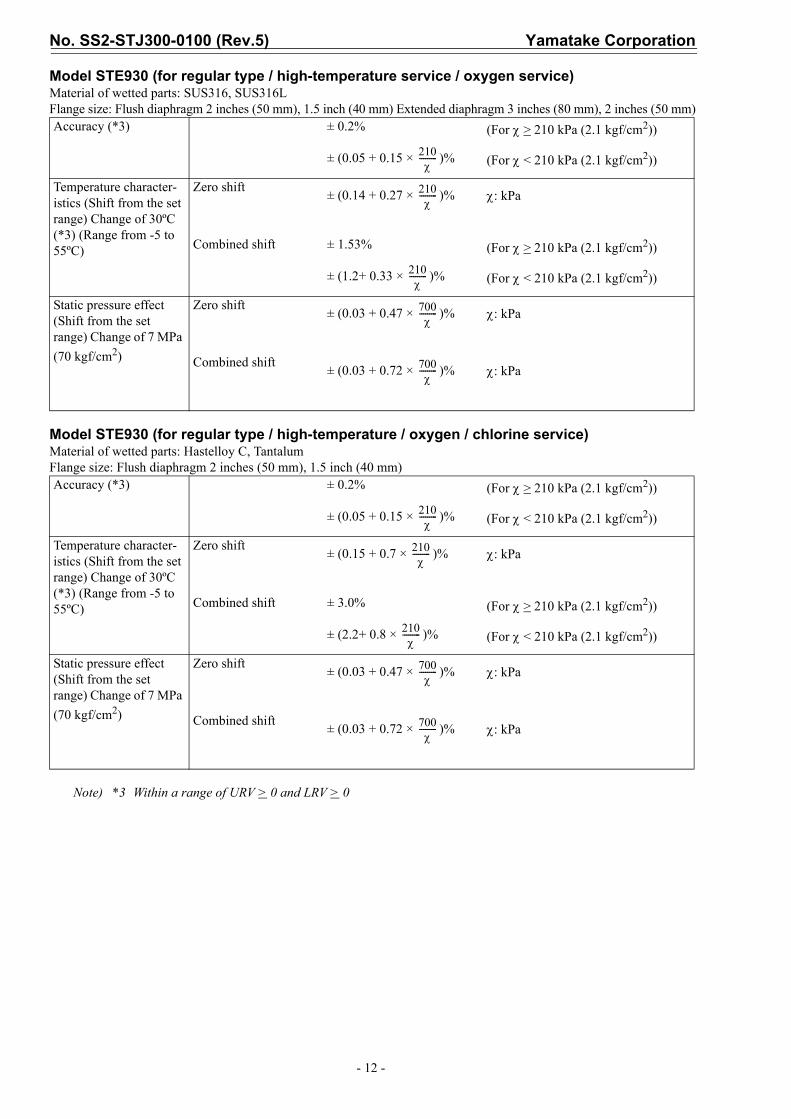
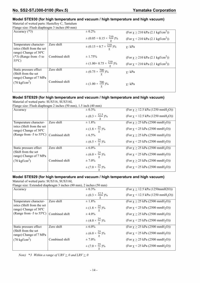
AccuracyShown for each item are the percentage ratio for (kPa), which is the greatest value of either the upper range value (URV)*1, the lower range value (LRV)*2 or the span.
Model STE929 (for regular type / high-temperature service / oxygen service)Material of wetted parts: SUS316, SUS316LFlange size: Flush diaphragm 3 inches (80 mm) Extended diaphragm 4 inches (100 mm)
Model STE930 (for regular type / high-temperature service / oxygen service)Material of wetted parts: SUS316, SUS316LFlange size: Flush diaphragm 3 inches (80 mm) Extended diaphragm 4 inches (100mm)
Note) *1 URV denotes the process value for 100% (20 mA DC) output*2 LRV denotes the process value for 0% (4 mA DC) output*3 Within a range of URV > 0 and LRV > 0
Accuracy ± 0.2% (For χ > 12.5 kPa (1250 mmH2O))
± (0.05 + 0.15 × )% (For χ < 12.5 kPa (1250 mmH2O))
Temperature character-istics (Shift from the set range) Change of 30ºC (Range from -5 to 55ºC)
Zero shift ± (0.14 + 0.27 × )% χ: kPa
Combined shift ± 0.71% (For χ > 25 kPa (2500 mmH2O))
± (0.38+ 0.33 × )% (For χ < 25 kPa (2500 mmH2O))
Static pressure effect (Shift from the set range) Change of 7 MPa (70 kgf/cm2)
Zero shift ± 0.75% (For χ > 25 kPa (2500 mmH2O))
± (0.75 × )% (For χ < 25 kPa (2500 mmH2O))
Combined shift ± 1.00% (For χ > 25 kPa (2500 mmH2O))
± (1.00 × )% (For χ < 25 kPa (2500 mmH2O))
Accuracy (*3) ± 0.2% (For χ > 210 kPa (2.1 kgf/cm2))
± (0.05 + 0.15 × )% (For χ < 210 kPa (2.1 kgf/cm2))
Temperature character-istics (Shift from the set range) Change of 30ºC (*3) (Range from -5 to 55ºC)
Zero shift ± (0.14 + 0.27 × )% χ: kPa
Combined shift ± 0.71% (For χ > 210 kPa (2.1 kgf/cm2))
± (0.38+ 0.33 × )% (For χ < 210 kPa (2.1 kgf/cm2))
Static pressure effect (Shift from the set range) Change of 7 MPa (70 kgf/cm2)
Zero shift ± (0.75 × )% χ: kPa
Combined shift ± (1.00 × )% χ: kPa
χ
12.5χ
----------
25χ------
25χ------
25χ------
25χ------
210χ
---------
210χ
---------
210χ
---------
700χ
---------
700χ
---------

Yamatake Corporation No. SS2-STJ300-0100 (Rev.5)
- 9 -
Model STE929 (for regular type / high-temperature / oxygen / chlorine service)Material of wetted parts: Hastelloy C, TantalumFlange size: Flush diaphragm 3 inches (80 mm)
Model STE930 (for regular type / high-temperature / oxygen / chlorine service)Material of wetted parts: Hastelloy C, TantalumFlange size: Flush diaphragm 3 inches (80 mm)
Note) *3 Within a range of URV > 0 and LRV > 0
Accuracy ± 0.4% (For χ > 12.5 kPa (1250 mmH2O))
± (0.4 × )% (For χ < 12.5 kPa (1250 mmH2O))
Temperature character-istics (Shift from the set range) Change of 30ºC (Range from -5 to 55ºC)
Zero shift ± 2.15% (For χ > 25 kPa (2500 mmH2O))
± (2.15 × )% (For χ < 25 kPa (2500 mmH2O))
Combined shift ± 3.0% (For χ > 25 kPa (2500 mmH2O))
± (3.0 × )% (For χ < 25 kPa (2500 mmH2O))
Static pressure effect (Shift from the set range) Change of 7 MPa (70 kgf/cm2)
Zero shift ± 6.00% (For χ > 25 kPa (2500 mmH2O))
± (6.00 × )% (For χ < 25 kPa (2500 mmH2O))
Combined shift ± 7.00% (For χ > 25 kPa (2500 mmH2O))
± (7.00 × )% (For χ < 25 kPa (2500 mmH2O))
Accuracy (*3) ± 0.2% (For χ > 210 kPa (2.1 kgf/cm2))
± (0.05 + 0.15 × )% (For χ < 210 kPa (2.1 kgf/cm2))
Temperature character-istics (Shift from the set range) Change of 30ºC (*3) (Range from -5 to 55ºC)
Zero shift ± (0.15 + 0.7 × )% χ: kPa
Combined shift ± 1.75% (For χ > 210 kPa (2.1 kgf/cm2))
± (1.00 + 0.75 × )% (For χ < 210 kPa (2.1 kgf/cm2))
Static pressure effect (Shift from the set range) Change of 7 MPa (70 kgf/cm2)
Zero shift ± (0.75 × )% χ: kPa
Combined shift ± (1.00 × )% χ: kPa
12.5χ
----------
25χ------
25χ------
25χ------
25χ------
210χ
---------
210χ
---------
210χ
---------
700χ
---------
700χ
---------
No. SS2-STJ300-0100 (Rev.5) Yamatake Corporation
- 10 -
Model STE929 (for regular type / high-temperature service / oxygen service)Material of wetted parts: SUS316, SUS316LFlange size: Flush diaphragm 2 inches (50 mm) Extended diaphragm 3 inches (80mm)
Model STE929 (for regular type / oxygen service)Material of wetted parts: SUS316, SUS316LFlange size: Flush diaphragm 1.5 inch (40 mm)
Model STE929 (for high-temperature service)Material of wetted parts: SUS316, SUS316LFlange size: Flush diaphragm 1.5 inch (40 mm)
Note) *3 Within a range of URV > 0 and LRV > 0
Accuracy ± 0.2% (For χ > 12.5 kPa (1250 mmH2O))
± (0.05 + 0.15 × )% (For χ < 12.5 kPa (1250 mmH2O))
Temperature character-istics (Shift from the set range) Change of 30ºC (Range from -5 to 55ºC)
Zero shift ± (0.14 + 0.27 × )% χ: kPa
Combined shift ± 0.88% (For χ > 25 kPa (2500 mmH2O))
± (0.55 + 0.33 × )% (For χ < 25 kPa (2500 mmH2O))
Static pressure effect (Shift from the set range) Change of 7 MPa (70 kgf/cm2)
Zero shift ± 1.47% (For χ > 25 kPa (2500 mmH2O))
± (1.47 × )% (For χ < 25 kPa (2500 mmH2O))
Combined shift ± 1.97% (For χ > 25 kPa (2500 mmH2O))
± (1.97 × )% (For χ < 25 kPa (2500 mmH2O))
Accuracy ± 0.3% (For χ > 12.5 kPa (1250 mmH2O))
± (0.3 × )% (For χ < 12.5 kPa (1250 mmH2O))
Temperature character-istics (Shift from the set range) Change of 30ºC (Range from -5 to 55ºC)
Zero shift ± 0.41% (For χ > 25 kPa (2500 mmH2O))
± (0.41 × )% (For χ < 25 kPa (2500 mmH2O))
Combined shift ± 0.88% (For χ > 25 kPa (2500 mmH2O))
± (0.88 × )% (For χ < 25 kPa (2500 mmH2O))
Static pressure effect (Shift from the set range) Change of 7 MPa (70 kgf/cm2)
Zero shift ± 1.47% (For χ > 25 kPa (2500 mmH2O))
± (1.47 × )% (For χ < 25 kPa (2500 mmH2O))
Combined shift ± 1.97% (For χ > 25 kPa (2500 mmH2O))
± (1.97 × )% (For χ < 25 kPa (2500 mmH2O))
Accuracy ± 0.3% (For χ > 12.5 kPa (1250 mmH2O))
± (0.3 × )% (For χ < 12.5 kPa (1250 mmH2O))
Temperature character-istics (Shift from the set range) Change of 30ºC (Range from -5 to 55ºC)
Zero shift ± 1.08% (For χ > 25 kPa (2500 mmH2O))
± (1.08 × )% (For χ < 25 kPa (2500 mmH2O))
Combined shift ± 6.54% (For χ > 25 kPa (2500 mmH2O))
± (6.54 × )% (For χ < 25 kPa (2500 mmH2O))
Static pressure effect (Shift from the set range) Change of 7 MPa (70 kgf/cm2)
Zero shift ± 2.7% (For χ > 25 kPa (2500 mmH2O))
± (2.7 × )% (For χ < 25 kPa (2500 mmH2O))
Combined shift ± 3.5% (For χ > 25 kPa (2500 mmH2O))
± (3.5 × )% (For χ < 25 kPa (2500 mmH2O))
12.5χ
----------
25χ------
25χ------
25χ------
25χ------
12.5χ
----------
25χ------
25χ------
25χ------
25χ------
12.5χ
----------
25χ------
25χ------
25χ------
25χ------

Yamatake Corporation No. SS2-STJ300-0100 (Rev.5)
- 11 -
Model STE929 (for regular type / high-temperature service / oxygen service)Material of wetted parts: SUS316, SUS316LFlange size: Extended diaphragm 2 inches (50 mm)
Model STE929 (for regular type / high-temperature / oxygen / chlorine service)Material of wetted parts: Hastelloy C, TantalumFlange size: Flush diaphragm 2 inches (50 mm), 1.5 inch (40 mm)
Note) *3 Within a range of URV > 0 and LRV > 0
Accuracy ± 0.3% (For χ > 12.5 kPa (1250 mmH2O))
± (0.3 × )% (For χ < 12.5 kPa (1250 mmH2O))
Temperature character-istics (Shift from the set range) Change of 30ºC (Range from -5 to 55ºC)
Zero shift ± 1.08% (For χ > 25 kPa (2500 mmH2O))
± (1.08 × )% (For χ < 25 kPa (2500 mmH2O))
Combined shift ± 6.54% (For χ > 25 kPa (2500 mmH2O))
± (6.54 × )% (For χ < 25 kPa (2500 mmH2O))
Static pressure effect (Shift from the set range) Change of 7 MPa (70 kgf/cm2)
Zero shift ± 2.7% (For χ > 25 kPa (2500 mmH2O))
± (2.7 × )% (For χ < 25 kPa (2500 mmH2O))
Combined shift ± 3.5% (For χ > 25 kPa (2500 mmH2O))
± (3.5 × )% (For χ < 25 kPa (2500 mmH2O))
Accuracy ± 0.4% (For χ > 12.5 kPa (1250 mmH2O))
± (0.4 × )% (For χ < 12.5 kPa (1250 mmH2O))
Temperature character-istics (Shift from the set range) Change of 30ºC (Range from -5 to 55ºC)
Zero shift ± 2.15% (For χ > 25 kPa (2500 mmH2O))
± (2.15 × )% (For χ < 25 kPa (2500 mmH2O))
Combined shift ± 6.55% (For χ > 25 kPa (2500 mmH2O))
± (6.55 × )% (For χ < 25 kPa (2500 mmH2O))
Static pressure effect (Shift from the set range) Change of 7 MPa (70 kgf/cm2)
Zero shift ± 6.00% (For χ > 25 kPa (2500 mmH2O))
± (6.00 × )% (For χ < 25 kPa (2500 mmH2O))
Combined shift ± 7.00% (For χ > 25 kPa (2500 mmH2O))
± (7.00 × )% (For χ < 25 kPa (2500 mmH2O))
12.5χ
----------
25χ------
25χ------
25χ------
25χ------
12.5χ
----------
25χ------
25χ------
25χ------
25χ------
No. SS2-STJ300-0100 (Rev.5) Yamatake Corporation
- 12 -
Model STE930 (for regular type / high-temperature service / oxygen service)Material of wetted parts: SUS316, SUS316LFlange size: Flush diaphragm 2 inches (50 mm), 1.5 inch (40 mm) Extended diaphragm 3 inches (80 mm), 2 inches (50 mm)
Model STE930 (for regular type / high-temperature / oxygen / chlorine service)Material of wetted parts: Hastelloy C, TantalumFlange size: Flush diaphragm 2 inches (50 mm), 1.5 inch (40 mm)
Note) *3 Within a range of URV > 0 and LRV > 0
Accuracy (*3) ± 0.2% (For χ > 210 kPa (2.1 kgf/cm2))
± (0.05 + 0.15 × )% (For χ < 210 kPa (2.1 kgf/cm2))
Temperature character-istics (Shift from the set range) Change of 30ºC (*3) (Range from -5 to 55ºC)
Zero shift ± (0.14 + 0.27 × )% χ: kPa
Combined shift ± 1.53% (For χ > 210 kPa (2.1 kgf/cm2))
± (1.2+ 0.33 × )% (For χ < 210 kPa (2.1 kgf/cm2))
Static pressure effect (Shift from the set range) Change of 7 MPa (70 kgf/cm2)
Zero shift ± (0.03 + 0.47 × )% χ: kPa
Combined shift ± (0.03 + 0.72 × )% χ: kPa
Accuracy (*3) ± 0.2% (For χ > 210 kPa (2.1 kgf/cm2))
± (0.05 + 0.15 × )% (For χ < 210 kPa (2.1 kgf/cm2))
Temperature character-istics (Shift from the set range) Change of 30ºC (*3) (Range from -5 to 55ºC)
Zero shift ± (0.15 + 0.7 × )% χ: kPa
Combined shift ± 3.0% (For χ > 210 kPa (2.1 kgf/cm2))
± (2.2+ 0.8 × )% (For χ < 210 kPa (2.1 kgf/cm2))
Static pressure effect (Shift from the set range) Change of 7 MPa (70 kgf/cm2)
Zero shift ± (0.03 + 0.47 × )% χ: kPa
Combined shift ± (0.03 + 0.72 × )% χ: kPa
210χ
---------
210χ
---------
210χ
---------
700χ
---------
700χ
---------
210χ
---------
210χ
---------
210χ
---------
700χ
---------
700χ
---------

Yamatake Corporation No. SS2-STJ300-0100 (Rev.5)
- 13 -
Model STE929 (for high temperature and vacuum / high temperature and high vacuum)Material of wetted parts: SUS316, SUS316LFlange size: Flush diaphragm 3 inches (80 mm) Extended diaphragm 4 inches (100mm)
Model STE930 (for high temperature and vacuum / high temperature and high vacuum)Material of wetted parts: SUS316, SUS316LFlange size: Flush diaphragm 3 inches (80 mm) Extended diaphragm 4 inches (100mm)
Model STE929 (for high temperature and vacuum / high temperature and high vacuum)Material of wetted parts: Hastelloy C, TantalumFlange size: Flush diaphragm 3 inches (80 mm)
Note) *3 Within a range of URV > 0 and LRV > 0
Accuracy ± 0.3% (For χ > 12.5 kPa (1250 mmH2O))
± (0.3 × )% (For χ < 12.5 kPa (1250 mmH2O))
Temperature character-istics (Shift from the set range) Change of 30ºC (Range from -5 to 55ºC)
Zero shift ± 0.81% (For χ > 25 kPa (2500 mmH2O))
± (0.81 × )% (For χ < 25 kPa (2500 mmH2O))
Combined shift ± 1.36% (For χ > 25 kPa (2500 mmH2O))
± (1.36 × )% (For χ < 25 kPa (2500 mmH2O))
Static pressure effect (Shift from the set range) Change of 7 MPa (70 kgf/cm2)
Zero shift ± 6.0% (For χ > 25 kPa (2500 mmH2O))
± (6.0 × )% (For χ < 25 kPa (2500 mmH2O))
Combined shift ± 7.0% (For χ > 25 kPa (2500 mmH2O))
± (7.0 × )% (For χ < 25 kPa (2500 mmH2O))
Accuracy (*3) ± 0.2% (For χ > 210 kPa (2.1 kgf/cm2))
± (0.05 + 0.15 × )% (For χ < 210 kPa (2.1 kgf/cm2))
Temperature character-istics (Shift from the set range) Change of 30ºC (*3) (Range from -5 to 55ºC)
Zero shift ± (0.15 + 0.7 × )% χ: kPa
Combined shift ± 1.75% (For χ > 210 kPa (2.1 kgf/cm2))
± (1.00+ 0.75 × )% (For χ < 210 kPa (2.1 kgf/cm2))
Static pressure effect (Shift from the set range) Change of 7 MPa (70 kgf/cm2)
Zero shift ± (0.75 × )% χ: kPa
Combined shift ± (1.00 × )% χ: kPa
Accuracy ± 0.4% (For χ > 12.5 kPa (1250 mmH2O))
± (0.4 × )% (For χ < 12.5 kPa (1250 mmH2O))
Temperature character-istics (Shift from the set range) Change of 30ºC (Range from -5 to 55ºC)
Zero shift ± 2.15% (For χ > 25 kPa (2500 mmH2O))
± (2.15 × )% (For χ < 25 kPa (2500 mmH2O))
Combined shift ± 3.0% (For χ > 25 kPa (2500 mmH2O))
± (3.0 × )% (For χ < 25 kPa (2500 mmH2O))
Static pressure effect (Shift from the set range) Change of 7 MPa (70 kgf/cm2)
Zero shift ± 6.00% (For χ > 25 kPa (2500 mmH2O))
± (6.00 × )% (For χ < 25 kPa (2500 mmH2O))
Combined shift ± 7.00% (For χ > 25 kPa (2500 mmH2O))
± (7.00 × )% (For χ < 25 kPa (2500 mmH2O))
12.5χ
----------
25χ------
25χ------
25χ------
25χ------
210χ
---------
210χ
---------
210χ
---------
700χ
---------
700χ
---------
12.5χ
----------
25χ------
25χ------
25χ------
25χ------
No. SS2-STJ300-0100 (Rev.5) Yamatake Corporation
- 14 -
Model STE930 (for high temperature and vacuum / high temperature and high vacuum)Material of wetted parts: Hastelloy C, TantalumFlange size: Flush diaphragm 3 inches (80 mm)
Model STE929 (for high temperature and vacuum / high temperature and high vacuum)Material of wetted parts: SUS316, SUS316LFlange size: Flush diaphragm 2 inches (50 mm), 1.5 inch (40 mm)
Model STE929 (for high temperature and vacuum / high temperature and high vacuum)Material of wetted parts: SUS316, SUS316LFlange size: Extended diaphragm 3 inches (80 mm), 2 inches (50 mm)
Note) *3 Within a range of URV > 0 and LRV > 0
Accuracy (*3) ± 0.2% (For χ > 210 kPa (2.1 kgf/cm2))
± (0.05 + 0.15 × )% (For χ < 210 kPa (2.1 kgf/cm2))
Temperature character-istics (Shift from the set range) Change of 30ºC (*3) (Range from -5 to 55ºC)
Zero shift ± (0.15 + 0.7 × )% χ: kPa
Combined shift ± 1.75% (For χ > 210 kPa (2.1 kgf/cm2))
± (1.00+ 0.75 × )% (For χ < 210 kPa (2.1 kgf/cm2))
Static pressure effect (Shift from the set range) Change of 7 MPa (70 kgf/cm2)
Zero shift ± (0.75 × )% χ: kPa
Combined shift ± (1.00 × )% χ: kPa
Accuracy ± 0.3% (For χ > 12.5 kPa (1250 mmH2O))
± (0.3 × )% (For χ < 12.5 kPa (1250 mmH2O))
Temperature character-istics (Shift from the set range) Change of 30ºC (Range from -5 to 55ºC)
Zero shift ± 1.8% (For χ > 25 kPa (2500 mmH2O))
± (1.8 × )% (For χ < 25 kPa (2500 mmH2O))
Combined shift ± 6.5% (For χ > 25 kPa (2500 mmH2O))
± (6.5 × )% (For χ < 25 kPa (2500 mmH2O))
Static pressure effect (Shift from the set range) Change of 7 MPa (70 kgf/cm2)
Zero shift ± 6.0% (For χ > 25 kPa (2500 mmH2O))
± (6.0 × )% (For χ < 25 kPa (2500 mmH2O))
Combined shift ± 7.0% (For χ > 25 kPa (2500 mmH2O))
± (7.0 × )% (For χ < 25 kPa (2500 mmH2O))
Accuracy ± 0.3% (For χ > 12.5 kPa (1250mmH2O))
± (0.3 × )% (For χ < 12.5 kPa (1250 mmH2O))
Temperature character-istics (Shift from the set range) Change of 30ºC (Range from -5 to 55ºC)
Zero shift ± 1.8% (For χ > 25 kPa (2500 mmH2O))
± (1.8 × )% (For χ < 25 kPa (2500 mmH2O))
Combined shift ± 4.0% (For χ > 25 kPa (2500 mmH2O))
± (4.0 × )% (For χ < 25 kPa (2500 mmH2O))
Static pressure effect (Shift from the set range) Change of 7 MPa (70 kgf/cm2)
Zero shift ± 6.0% (For χ > 25 kPa (2500 mmH2O))
± (6.0 × )% (For χ < 25 kPa (2500 mmH2O))
Combined shift ± 7.0% (For χ > 25 kPa (2500 mmH2O))
± (7.0 × )% (For χ < 25 kPa (2500 mmH2O))
210χ
---------
210χ
---------
210χ
---------
700χ
---------
700χ
---------
12.5χ
----------
25χ------
25χ------
25χ------
25χ------
12.5χ
----------
25χ------
25χ------
25χ------
25χ------

Yamatake Corporation No. SS2-STJ300-0100 (Rev.5)
- 15 -
Model STE930 (for high temperature and vacuum / high temperature and high vacuum)Material of wetted parts: SUS316, SUS316LFlange size: Flush diaphragm 2 inches (50 mm), 1.5 inch (40 mm) Extended diaphragm 3 inches (80mm), 2 inches (50 mm)
Model STE929 (for high temperature and vacuum / high temperature and high vacuum)Material of wetted parts: Hastelloy C, TantalumFlange size: Flush diaphragm 2 inches (50 mm), 1.5 inch (40 mm)
Model STE930 (for high temperature and vacuum / high temperature and high vacuum)Material of wetted parts: Hastelloy C, TantalumFlange size: Flush diaphragm 2 inches (50 mm), 1.5 inch (40 mm)
Note) *3 Within a range of URV > 0 and LRV > 0
Accuracy (*3) ± 0.2% (For χ > 210 kPa (2.1 kgf/cm2))
± (0.2 × )% (For χ < 210 kPa (2.1 kgf/cm2))
Temperature character-istics (Shift from the set range) Change of 30ºC (*3) (Range from -5 to 55ºC)
Zero shift ± (0.15 + 0.7 × )% χ: kPa
Combined shift ± 1.87% (For χ > 210 kPa (2.1 kgf/cm2))
± (1.2+ 0.67 × )% (For χ < 210 kPa (2.1 kgf/cm2))
Static pressure effect (Shift from the set range) Change of 7 MPa (70 kgf/cm2)
Zero shift ± (0.75 × )% χ: kPa
Combined shift ± (1.0 × )% χ: kPa
Accuracy ± 0.4% (For χ > 12.5 kPa (1250 mmH2O))
± (0.4 × )% (For χ < 12.5 kPa (1250 mmH2O))
Temperature character-istics (Shift from the set range) Change of 30ºC (Range from -5 to 55ºC)
Zero shift ± 2.15% (For χ > 25 kPa (2500 mmH2O))
± (2.15 × )% (For χ < 25 kPa (2500 mmH2O))
Combined shift ± 6.55% (For χ > 25 kPa (2500 mmH2O))
± (6.55 × )% (For χ < 25 kPa (2500 mmH2O))
Static pressure effect (Shift from the set range) Change of 7 MPa (70 kgf/cm2)
Zero shift ± 6.00% (For χ > 25 kPa (2500 mmH2O))
± (6.00 × )% (For χ < 25 kPa (2500 mmH2O))
Combined shift ± 7.00% (For χ > 25 kPa (2500 mmH2O))
± (7.00 × )% (For χ < 25 kPa (2500 mmH2O))
Accuracy (*3) ± 0.2% (For x > 210 kPa (2.1 kgf/cm2))
± (0.05 + 0.15 × )% (For x < 210 kPa (2.1 kgf/cm2))
Temperature character-istics (Shift from the set range) Change of 30ºC (*3) (Range from -5 to 55ºC)
Zero shift ± (0.15 + 0.7 × )% x: kPa
Combined shift ± 3.0% (For x > 210 kPa (2.1 kgf/cm2))
± (2.2+ 0.8 × )% (For x < 210 kPa (2.1 kgf/cm2))
Static pressure effect (Shift from the set range) Change of 7 MPa (70 kgf/cm2)
Zero shift ± (0.75 × )% x: kPa
Combined shift ± (1.0 × )% x: kPa
210χ
---------
210χ
---------
210χ
---------
700χ
---------
700χ
---------
12.5χ
----------
25χ------
25χ------
25χ------
25χ------
210χ
---------
210χ
---------
210χ
---------
700χ
---------
700χ
---------

No. SS2-STJ300-0100 (Rev.5) Yamatake Corporation
- 16 -
MODEL SELECTIONST3000 series 900 electric difference pressure transmitterModel STE929 / STE930 (Remote-sealed diaphragm type)Flush diaphragm 3 inches (80 mm) for regular / high-temperature serviceModel No.: STE9XX - I II III IV V VI VII VIII - Option I - Option II
(Continued)
Basic Model No.
Measuring span2.5 to 100 kPa (250 to 10,160 mmH2O) STE929
Flush diaphragm flange type: 3 inches (80 mm)35 to 700 kPa (0.35 to 7 kgf/cm2) STE930
SelectionCode
Fill fluid codeI Fill fluid Model No. Fill fluid 1 2 3 5
STE929Flush diaphragm 3 inches (80 mm)
Regular type service (Silicone oil) 1For oxygen service (Fluorine oil) *3 2For high-temperature service (Silicone oil) *17 3For chlorine service (Fluorine oil) *3 5
STE930Flush diaphragm3 inches (80 mm)
Regular type service (Silicone oil) 1For oxygen service (Fluorine oil) *3 2For high-temperature service (Silicone oil) *17 3For chlorine service (Fluorine oil) *3 5
II Flange standard ANSI flange A a a a a
JIS flange J a a a a
JPI flange P a a a a
III Flange type & rating
JIS 10K, ANSI/JPI 150 (RF) equivalent A a a a a
JIS 20K, ANSI/JPI 300 (RF) equivalent B a a a a
JIS 30K, ANSI/JPI 600 (RF) equivalent C a a a a
IV Flange material Carbon steel 1 a a a a
SUS304 7 a a a a
SUS316 2 a a a a
SUS316L 8 a a a a
V Material of wetted parts SUS316 (Diaphragm: SUS316L, others: SUS316) 2 a a a
SUS316L (Diaphragm: SUS316L, others: SUS316L) 8 a a a
Tantalum (Diaphragm: Tantalum, others: Tantalum) *17 4 a a a a
Hastelloy C (Diaphragm: Hastelloy C, others: Hastelloy C) 9 a a a
VI Finish of gasket face Standard (JIS Ra3.2 (12.5S)) J a a a a
VII Length of extended parts Flush diaphragm 3 inches (80 mm) 00 a a a a
VIII Length of capillary tube 2 m 2 a a a a
3 m 3 a a a a
4 m 4 a a a a
5 m 5 a a a a
6 m 6 a a a a
7 m 7 a a a a
8 m 8 a a a a
9 m 9 a a a a
10 m A a a a a
Length of capillary tube with olefin coating
2 m B a a a a
3 m C a a a a
4 m H a a a a
5 m D a a a a
6 m J a a a a
7 m E a a a a
8 m F a a a a
9 m K a a a a
10 m G a a a a
Yamatake Corporation No. SS2-STJ300-0100 (Rev.5)
- 17 -
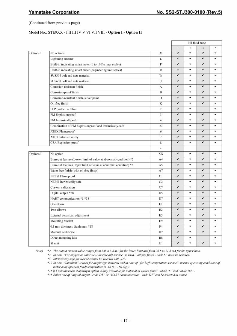
(Continued from previous page)
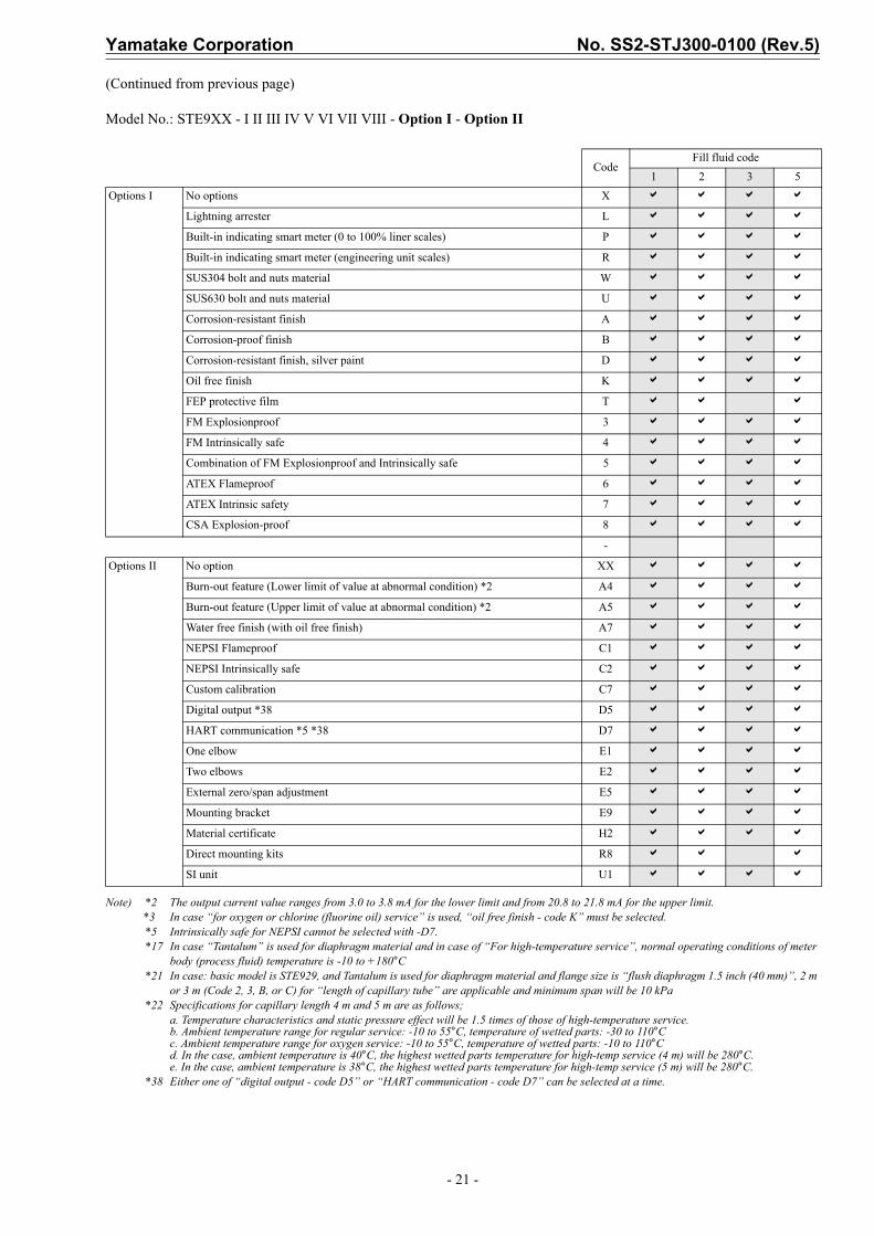
Model No.: STE9XX - I II III IV V VI VII VIII - Option I - Option II
Note) *2 The output current value ranges from 3.0 to 3.8 mA for the lower limit and from 20.8 to 21.8 mA for the upper limit.*3 In case “For oxygen or chlorine (Fluorine oil) service” is used, “oil free finish - code K” must be selected. *5 Intrinsically safe for NEPSI cannot be selected with -D7.*17 In case “Tantalum” is used for diaphragm material and in case of “for high-temperature service”, normal operating conditions of
meter body (process fluid) temperature is -10 to +180 dig.C*18 0.1 mm thickness diaphragm option is only available for material of wetted parts: “SUS316” and “SUS316L”.*38 Either one of “digital output - code D5” or “HART communication - code D7” can be selected at a time.
Fill fluid code1 2 3 5
Options I No options X a a a a
Lightning arrester L a a a a
Built-in indicating smart meter (0 to 100% liner scales) P a a a a
Built-in indicating smart meter (engineering unit scales) R a a a a
SUS304 bolt and nuts material W a a a a
SUS630 bolt and nuts material U a a a a
Corrosion-resistant finish A a a a a
Corrosion-proof finish B a a a a
Corrosion-resistant finish, silver paint D a a a a
Oil free finish K a a a a
FEP protective film T a a a
FM Explosionproof 3 a a a a
FM Intrinsically safe 4 a a a a
Combination of FM Explosionproof and Intrinsically safe 5 a a a a
ATEX Flameproof 6 a a a a
ATEX Intrinsic safety 7 a a a a
CSA Explosion-proof 8 a a a a
-
Options II No option XX a a a a
Burn-out feature (Lower limit of value at abnormal condition) *2 A4 a a a a
Burn-out feature (Upper limit of value at abnormal condition) *2 A5 a a a a
Water free finish (with oil free finish) A7 a a a a
NEPSI Flameproof C1 a a a a
NEPSI Intrinsically safe C2 a a a a
Custom calibration C7 a a a a
Digital output *38 D5 a a a a
HART communication *5 *38 D7 a a a a
One elbow E1 a a a a
Two elbows E2 a a a a
External zero/span adjustment E5 a a a a
Mounting bracket E9 a a a a
0.1 mm thickness diaphragm *18 F4 a a a a
Material certificate H2 a a a a
Direct mounting kits R8 a a a
SI unit U1 a a a a

No. SS2-STJ300-0100 (Rev.5) Yamatake Corporation
- 18 -
ST3000 series 900 electric difference pressure transmitterModel STE929 / STE930 (Remote-sealed diaphragm type)Extended diaphragm 4 inches (100 mm)for regular / high-temperature serviceModel No.: STE9XX - I II III IV V VI VII VIII - Option I - Option II
(Continued)
Basic Model No.
Measuring span2.5 to 100 kPa (250 to 10,160 mmH2O) STE929 Extended diaphragm flange type: 4 inches (100
mm)35 to 700 kPa (0.35 to 7 kgf/cm2) STE930
SelectionCode
Fill fluid codeI Fill fluid Flange type Fill fluid 1 2 3
STE929Extended diaphragm4 inches (100 mm)
Regular type service (Silicone oil) *16 1For oxygen service (Fluorine oil) *3 *16 2For high-temperature service (Silicone oil) *19 *20 3
STE930Extended diaphragm4 inches (100 mm)
Regular type service (Silicone oil) *16 1For oxygen service (Fluorine oil) *3 *16 2For high-temperature service (Silicone oil) *19 *20 3
II Flange standard ANSI flange A a a a
JIS flange J a a a
JPI flange P a a a
III Flange type & rating JIS 10K, ANSI/JPI 150 (RF) equivalent A a a a
JIS 20K, ANSI/JPI 300 (RF) equivalent *19 B a a a
JIS 30K *16 *20 C a a a
IV Flange material Carbon steel 1 a a a
SUS304 7 a a a
SUS316 2 a a a
SUS316L *16 *19 *20 8 a a a
V Material of wetted parts SUS316 (Diaphragm: SUS316L, others: SUS316) 2 a a a
SUS316L (Diaphragm: SUS316L, others: SUS316L) *16 *19 *20 8 a a a
VI Finish of gasket face Standard (JIS Ra3.2 (12.5S)) J a a a
VII Length of extended parts
L = 50 mm (4 inches / 100 mm) *20 09 a a a
L = 100 mm (4 inches / 100 mm) *20 14 a a a
L = 150 mm (4 inches / 100 mm) *16 *20 19 a a a
L = 200 mm (4 inches / 100 mm) *16 *20 24 a a a
L = 250 mm (4 inches / 100 mm) *16 *19 *20 29 a a a
L = 300 mm (4 inches / 100 mm) *16 *19 *20 34 a a a
VIII Length of capillary tube 2 m 2 a a a
3 m 3 a a a
4 m 4 a a a
5 m 5 a a a
6 m 6 a a a
7 m 7 a a a
8 m 8 a a a
9 m 9 a a a
10 m A a a a
Length of capillary tube with olefin coating
2 m B a a a
3 m C a a a
4m H a a a
5 m D a a a
6 m J a a a
7 m E a a a
8 m F a a a
9 m K a a a
10 m G a a a

Yamatake Corporation No. SS2-STJ300-0100 (Rev.5)
- 19 -
(Continued from previous page)
Model No.: STE9XX - I II III IV V VI VII VIII - Option I - Option II
Note) *2 The output current value ranges from 3.0 to 3.8 mA for the lower limit and from 20.8 to 21.8 mA for the upper limit.*3 In case “for oxygen or chlorine (fluorine oil) service” is used, “oil free finish - code K” must be selected.*5 Intrinsically safe for NEPSI cannot be selected with -D7.*15 Only available for material of wetted parts: “SUS316” and “SUS316L”.*16 In case “JIS30K” is used for flange type and rating. “SUS316L” is used for flange material and for regular service or oxygen
service, not available for length of extended parts: 150 / 200 / 250 / 300 mm.*19 In case fill fluid: for high-temperature service and flange rating: ANSI300 and wetted parts material: SUS316L, extended
length of flange 250 / 300 mm are not available.*20 In case flange rating: JIS30K and wetted parts material: SUS316L, and for high temperature service, extended diaphragm type
is not available.*38 Either one of “digital output - code D5” or “HART communication - code D7” can be selected at a time.
CodeFill fluid code
1 2 3Options I No options X a a a
Lightning arrester L a a a
Built-in indicating smart meter (0 to 100% liner scales) P a a a
Built-in indicating smart meter (engineering unit scales) R a a a
SUS304 bolt and nuts material W a a a
SUS630 bolt and nuts material U a a a
Corrosion-resistant finish A a a a
Corrosion-proof finish B a a a
Corrosion-resistant finish, silver paint D a a a
Oil free finish K a a a
FM Explosionproof 3 a a a
FM Intrinsically safe 4 a a a
Combination of FM Explosionproof and Intrinsically safe 5 a a a
ATEX Flameproof 6 a a a
ATEX Intrinsic safety 7 a a a
CSA Explosion-proof 8 a a a
-
Options II No option XX a a a
Burn-out feature (Lower limit of value at abnormal condition) *2 A4 a a a
Burn-out feature (Upper limit of value at abnormal condition) *2 A5 a a a
Water free finish (with oil free finish) A7 a a a
NEPSI Flameproof C1 a a a
NEPSI Intrinsically safe C2 a a a
Custom calibration C7 a a a
Digital output D5 a a a
HART communication *5 D7 a a a
One elbow E1 a a a
Two elbows E2 a a a
External zero/span adjustment E5 a a a
Mounting bracket E9 a a a
0.1 mm thickness diaphragm *15 F4 a a a
Material certificate H2 a a a
Direct mounting kits R8 a a
SI unit U1 a a a

No. SS2-STJ300-0100 (Rev.5) Yamatake Corporation
- 20 -
ST3000 series 900 electric difference pressure transmitterModel STE929 / STE930 (Remote-sealed diaphragm type)Flush diaphragm 2 inches (50 mm), 1.5 inch (40 mm)for regular / high-temperature serviceModel No.: STE9XX - I II III IV V VI VII VIII - Option I - Option II
(Continued)
Basic Model No.
Measuring span2.5 to 100 kPa (250 to 10,160 mmH2O) STE929 Flush diaphragm type:
2 inches (50 mm), 1.5 inch (40 mm)35 to 700 kPa (0.35 to 7 kgf/cm2) STE930
SelectionCode
Fill Fluid CodeI Fill fluid Flange type Fill fluid 1 2 3 5
STE929Flush diaphragm2 inches (50 mm)1.5 inch (40 mm)
Regular type service (Silicone oil) 1
For oxygen service (Fluorine oil) *3 2
For high-temperature service (Silicone oil) *17 3
For chlorine service (Fluorine oil) *3 5
STE930Flush diaphragm2 inches (50 mm)1.5 inch (40 mm)
Regular type service (Silicone oil) 1
For oxygen service (Fluorine oil) *3 2
For high-temperature service (Silicone oil) *17 3
For chlorine service (Fluorine oil) *3 5
II Flange standard ANSI flange A a a a a
JIS flange J a a a a
JPI flange P a a a a
III Flange type & rating JIS 10K, ANSI/JPI 150 (RF) equivalent A a a a a
JIS 20K, ANSI/JPI 300 (RF) equivalent B a a a a
JIS 30K, ANSI/JPI 600 (RF) equivalent C a a a a
IV Flange material Carbon Steel 1 a a a a
SUS304 7 a a a a
SUS316 2 a a a a
SUS316L 8 a a a a
V Material of wetted parts SUS316 (Diaphragm: SUS316L, others: SUS316) 2 a a a
SUS316L (Diaphragm: SUS316L, others: SUS316L) 8 a a a
Tantalum (Diaphragm: Tantalum, others: Tantalum) *17 *21 4 a a a
Hastelloy C (Diaphragm: Hastelloy C, others: Hastelloy C) 9 a a a
VI Finish of gasket face Standard (JIS Ra3.2 (12.5S)) J a a a a
VII Length of extended parts Flush diaphragm 2 inches (50 mm) 01 a a a a
Flush diaphragm 1.5 inch (40 mm) *21 02 a a a a
VIII Length of capillary tube 2 m 2 a a a a
3 m 3 a a a a
4 m *22 4 a a a a
5 m *22 5 a a a a
Length of capillary tube with olefin coating
2 m B a a a a
3 m C a a a a
4 m *22 H a a a a
5 m *22 D a a a a
Yamatake Corporation No. SS2-STJ300-0100 (Rev.5)
- 21 -
(Continued from previous page)
Model No.: STE9XX - I II III IV V VI VII VIII - Option I - Option II
Note) *2 The output current value ranges from 3.0 to 3.8 mA for the lower limit and from 20.8 to 21.8 mA for the upper limit.*3 In case “for oxygen or chlorine (fluorine oil) service” is used, “oil free finish - code K” must be selected.*5 Intrinsically safe for NEPSI cannot be selected with -D7.*17 In case “Tantalum” is used for diaphragm material and in case of “For high-temperature service”, normal operating conditions of meter
body (process fluid) temperature is -10 to +180°C*21 In case: basic model is STE929, and Tantalum is used for diaphragm material and flange size is “flush diaphragm 1.5 inch (40 mm)”, 2 m
or 3 m (Code 2, 3, B, or C) for “length of capillary tube” are applicable and minimum span will be 10 kPa *22 Specifications for capillary length 4 m and 5 m are as follows;
a. Temperature characteristics and static pressure effect will be 1.5 times of those of high-temperature service.b. Ambient temperature range for regular service: -10 to 55°C, temperature of wetted parts: -30 to 110°Cc. Ambient temperature range for oxygen service: -10 to 55°C, temperature of wetted parts: -10 to 110°Cd. In the case, ambient temperature is 40°C, the highest wetted parts temperature for high-temp service (4 m) will be 280°C.e. In the case, ambient temperature is 38°C, the highest wetted parts temperature for high-temp service (5 m) will be 280°C.
*38 Either one of “digital output - code D5” or “HART communication - code D7” can be selected at a time.
CodeFill fluid code
1 2 3 5Options I No options X a a a a
Lightning arrester L a a a a
Built-in indicating smart meter (0 to 100% liner scales) P a a a a
Built-in indicating smart meter (engineering unit scales) R a a a a
SUS304 bolt and nuts material W a a a a
SUS630 bolt and nuts material U a a a a
Corrosion-resistant finish A a a a a
Corrosion-proof finish B a a a a
Corrosion-resistant finish, silver paint D a a a a
Oil free finish K a a a a
FEP protective film T a a a
FM Explosionproof 3 a a a a
FM Intrinsically safe 4 a a a a
Combination of FM Explosionproof and Intrinsically safe 5 a a a a
ATEX Flameproof 6 a a a a
ATEX Intrinsic safety 7 a a a a
CSA Explosion-proof 8 a a a a
-
Options II No option XX a a a a
Burn-out feature (Lower limit of value at abnormal condition) *2 A4 a a a a
Burn-out feature (Upper limit of value at abnormal condition) *2 A5 a a a a
Water free finish (with oil free finish) A7 a a a a
NEPSI Flameproof C1 a a a a
NEPSI Intrinsically safe C2 a a a a
Custom calibration C7 a a a a
Digital output *38 D5 a a a a
HART communication *5 *38 D7 a a a a
One elbow E1 a a a a
Two elbows E2 a a a a
External zero/span adjustment E5 a a a a
Mounting bracket E9 a a a a
Material certificate H2 a a a a
Direct mounting kits R8 a a a
SI unit U1 a a a a

No. SS2-STJ300-0100 (Rev.5) Yamatake Corporation
- 22 -
ST3000 series 900 electric difference pressure transmitterModel STE929 / STE930 (Remote-sealed diaphragm type)Extended diaphragm 3 inches (80 mm), 2 inches (50 mm)for regular / high-temperature serviceModel No.: STE9XX - I II III IV V VI VII VIII - Option I - Option II
(Continued)
Basic Model No.
Measuring span2.5 to 100 kPa (250 to 10,160 mmH2O) STE929 Extended diaphragm type:
3 inches (80 mm), 2 inches (50 mm)35 to 700 kPa (0.35 to 7 kgf/cm2) STE930
Selection ICode
Fill fluid codeI Fill fluid Flange type Fill fluid 1 2 3
STE929Extended diaphragm3 inches (80 mm)2 inches (50 mm)
Regular type service (Silicone oil) 1For oxygen service (Fluorine oil) *3 2For high-temperature service(Silicone oil)
3
STE930Extended diaphragm3 inches (80 mm)2 inches (50 mm)
Regular type service (Silicone oil) 1For oxygen service (Fluorine oil) *3 2For high-temperature service(Silicone oil) *31
3
II Flange standard ANSI flange A a a a
JIS flange J a a a
JPI flange P a a a
III Flange type & rating
JIS 10K, ANSI/JPI 150 (RF) equivalent A a a a
JIS 20K, ANSI/JPI 300 (RF) equivalent B a a a
JIS 30K, ANSI/JPI 600 (RF) equivalent *24 *31 C a a a
IV Flange material Carbon Steel 1 a a a
SUS304 7 a a a
SUS316 2 a a a
SUS316L 8 a a a
V Material of wetted parts SUS316 (Diaphragm: SUS316L, others: SUS316) 2 a a a
SUS316L (Diaphragm: SUS316L, others: SUS316L) *31 8 a a a
VI Finish of gasket face Standard (JIS Ra3.2 (12.5S)) J a a a
VII Length of extended parts
L = 50 mm (3 inches / 80 mm) *24 05 a a a
L = 100 mm (3 inches / 80 mm) *24 10 a a a
L = 150 mm (3 inches / 80 mm) *24 15 a a a
L = 200 mm (3 inches / 80 mm) *24 20 a a a
L = 250 mm (3 inches / 80 mm) *24 25 a a a
L = 300 mm (3 inches / 80 mm) *24 30 a a a
L = 50 mm (2 inches / 50 mm) *24 06 a a a
L = 100 mm (2 inches / 50 mm) *24 11 a a a
L = 150 mm (2 inches / 50 mm) *24 16 a a a
L = 200 mm (2 inches / 50 mm) *24 *31 21 a a a
L = 250 mm (2 inches / 50 mm) *24 *31 26 a a a
L = 300 mm (2 inches / 50 mm) *24 *31 31 a a a
VIII Length of capillary tube 2 m 2 a a a
3 m 3 a a a
4 m *22 4 a a a
5 m *22 5 a a a
Length of capillary tube with olefin coating
2 m B a a a
3 m C a a a
4 m *22 H a a a
5 m *22 D a a a

Yamatake Corporation No. SS2-STJ300-0100 (Rev.5)
- 23 -
(Continued from previous page)
Model No.: STE9XX - I II III IV V VI VII VIII - Option I - Option II
Note) *2 The output current value ranges from 3.0 to 3.8 mA for the lower limit and from 20.8 to 21.8 mA for the upper limit.*3 In case “for oxygen or chlorine (fluorine oil) service” is used, “oil free finish - code K” must be selected.*5 Intrinsically safe for NEPSI cannot be selected with -D7.*22 Specifications for capillary length 4 m and 5 m are as follows;
a. Temperature characteristics and static pressure effect will be 1.5 times of those of high-temperature service.b. Ambient temperature range for regular service: -10 to 55°C, temperature of wetted parts: -30 to 110°Cc. Ambient temperature range for oxygen service: -10 to 55°C, temperature of wetted parts: -10 to 110°Cd. In the case, ambient temperature is 40°C, the highest wetted parts temperature for high-temp service (4 m) will be 280°C.e. In the case, ambient temperature is 38°C, the highest wetted parts temperature for high-temp service (5 m) will be 280°C.
*24 In case of “ANSI/JPI600” is used for 3 inches flange type and rating, not available for the extended diaphragm flange type.*31 In case fill fluid: For high-temperature service, for high-temperature vacuum service or high-temperature high vacuum service and 2
inches flange rating: ANSI/JPI 600 and wetted parts material: SUS316L, extension length of flange 200 / 250 / 300 mm are not available.*38 Either one of “digital output - code D5” or “HART communication - code D7” can be selected at a time.
CodeFill fluid code
1 2 3Options I No options X a a a
Lightning arrester L a a a
Built-in indicating smart meter (0 to 100% liner scales) P a a a
Built-in indicating smart meter (engineering unit scales) R a a a
SUS304 bolt and nuts material W a a a
SUS630 bolt and nuts material U a a a
Corrosion-resistant finish A a a a
Corrosion-proof finish B a a a
Corrosion-resistant finish, silver paint D a a a
Oil free finish K a a a
FM Explosionproof 3 a a a
FM Intrinsically safe 4 a a a
Combination of FM Explosionproof and Intrinsically safe 5 a a a
ATEX Flameproof 6 a a a
ATEX Intrinsic safety 7 a a a
CSA Explosion-proof 8 a a a
-
Options II No option XX a a a
Burn-out feature (Lower limit of value at abnormal condition) *2 A4 a a a
Burn-out feature (Upper limit of value at abnormal condition) *2 A5 a a a
Water free finish (with oil free finish) A7 a a a
NEPSI Flameproof C1 a a a
NEPSI Intrinsically safe C2 a a a
Custom calibration C7 a a a
Digital output *38 D5 a a a
HART communication *5 *38 D7 a a a
One elbow E1 a a a
Two elbows E2 a a a
External zero/span adjustment E5 a a a
Mounting bracket E9 a a a
Material certificate H2 a a a
Direct mounting kits R8 a a
SI unit U1 a a a
No. SS2-STJ300-0100 (Rev.5) Yamatake Corporation
- 24 -
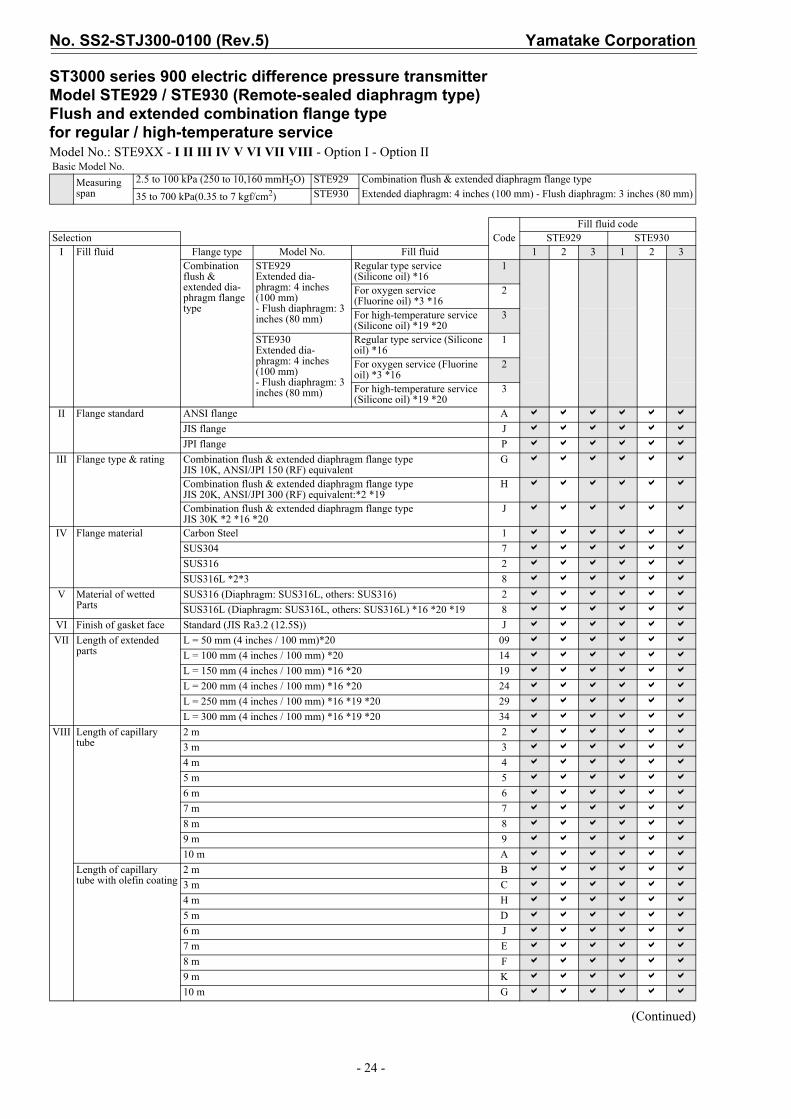
ST3000 series 900 electric difference pressure transmitterModel STE929 / STE930 (Remote-sealed diaphragm type)Flush and extended combination flange typefor regular / high-temperature serviceModel No.: STE9XX - I II III IV V VI VII VIII - Option I - Option II
(Continued)
Basic Model No.Measuring span
2.5 to 100 kPa (250 to 10,160 mmH2O) STE929 Combination flush & extended diaphragm flange type35 to 700 kPa(0.35 to 7 kgf/cm2) STE930 Extended diaphragm: 4 inches (100 mm) - Flush diaphragm: 3 inches (80 mm)
CodeFill fluid code
Selection STE929 STE930I Fill fluid Flange type Model No. Fill fluid 1 2 3 1 2 3
Combination flush & extended dia-phragm flange type
STE929Extended dia-phragm: 4 inches (100 mm)- Flush diaphragm: 3 inches (80 mm)
Regular type service(Silicone oil) *16
1
For oxygen service(Fluorine oil) *3 *16
2
For high-temperature service (Silicone oil) *19 *20
3
STE930Extended dia-phragm: 4 inches (100 mm)- Flush diaphragm: 3 inches (80 mm)
Regular type service (Silicone oil) *16
1
For oxygen service (Fluorine oil) *3 *16
2
For high-temperature service (Silicone oil) *19 *20
3
II Flange standard ANSI flange A a a a a a aJIS flange J a a a a a aJPI flange P a a a a a a
III Flange type & rating Combination flush & extended diaphragm flange type JIS 10K, ANSI/JPI 150 (RF) equivalent
G a a a a a a
Combination flush & extended diaphragm flange type JIS 20K, ANSI/JPI 300 (RF) equivalent:*2 *19
H a a a a a a
Combination flush & extended diaphragm flange type JIS 30K *2 *16 *20
J a a a a a a
IV Flange material Carbon Steel 1 a a a a a aSUS304 7 a a a a a aSUS316 2 a a a a a aSUS316L *2*3 8 a a a a a a
V Material of wetted Parts
SUS316 (Diaphragm: SUS316L, others: SUS316) 2 a a a a a aSUS316L (Diaphragm: SUS316L, others: SUS316L) *16 *20 *19 8 a a a a a a
VI Finish of gasket face Standard (JIS Ra3.2 (12.5S)) J a a a a a aVII Length of extended
partsL = 50 mm (4 inches / 100 mm)*20 09 a a a a a aL = 100 mm (4 inches / 100 mm) *20 14 a a a a a aL = 150 mm (4 inches / 100 mm) *16 *20 19 a a a a a aL = 200 mm (4 inches / 100 mm) *16 *20 24 a a a a a aL = 250 mm (4 inches / 100 mm) *16 *19 *20 29 a a a a a aL = 300 mm (4 inches / 100 mm) *16 *19 *20 34 a a a a a a
VIII Length of capillary tube
2 m 2 a a a a a a3 m 3 a a a a a a4 m 4 a a a a a a5 m 5 a a a a a a6 m 6 a a a a a a7 m 7 a a a a a a8 m 8 a a a a a a9 m 9 a a a a a a10 m A a a a a a a
Length of capillary tube with olefin coating
2 m B a a a a a a3 m C a a a a a a4 m H a a a a a a5 m D a a a a a a6 m J a a a a a a7 m E a a a a a a8 m F a a a a a a9 m K a a a a a a10 m G a a a a a a

Yamatake Corporation No. SS2-STJ300-0100 (Rev.5)
- 25 -
(Continued from previous page)
Model No.: STE9XX - I II III IV V VI VII VIII - Option I - Option II
Note) *2 The output current value ranges from 3.0 to 3.8 mA for the lower limit and from 20.8 to 21.8 mA for the upper limit.*3 In case “for oxygen or chlorine (fluorine oil) service” is used, “oil free finish - code K” must be selected.*5 Intrinsically safe for NEPSI cannot be selected with -D7.*16 In case “JIS30K” is used for flange type and rating, “SUS316L” is used for flange material and for regular service or oxygen service, not
available for length of extended parts: 150/200/250/300 mm.*19 In case fill fluid: for high-temperature service and Flange Rating: ANSI300 and wetted parts material: SUS316L, extension length of
Flange 250mm / 300mm are not available.*20 In case flange rating: JIS30K and wetted parts material: SUS316L, extended diaphragm type is not available.*38 Either one of “digital output - code D5” or “HART communication - code D7” can be selected at a time.
Notes of order entry
CodeFill fluid code
STE929 STE9301 2 3 1 2 3
Options I No options X a a a a a a
Lightning arrester L a a a a a a
Built-in indicating smart meter (0 to 100% liner scales) P a a a a a a
Built-in indicating smart meter (engineering unit scales) R a a a a a a
SUS304 Bolt and nuts material W a a a a a a
SUS630 Bolt and nuts material U a a a a a a
Corrosion-resistant finish A a a a a a a
Corrosion-proof finish B a a a a a a
Corrosion-resistant finish, silver paint D a a a a a a
Oil free finish K a a a a a a
FEP protective film T a a a a
FM Explosionproof 3 a a a a a a
FM Intrinsically safe 4 a a a a a a
Combination of FM Explosionproof and Intrinsically safe 5 a a a a a a
ATEX Flameproof 6 a a a a a a
ATEX Intrinsic safety 7 a a a a a a
CSA Explosion-proof 8 a a a a a a
-
Options II No option XX a a a a a a
Burn-out feature (Lower limit of value at abnormal condition) *2 A4 a a a a a a
Burn-out feature (Upper limit of value at abnormal condition) *2 A5 a a a a a a
Water free finish (with oil free finish) A7 a a a a a a
NEPSI Flameproof C1 a a a a a a
NEPSI Intrinsically safe C2 a a a a a a
Custom calibration C7 a a a a a a
Digital output *38 D5 a a a a a a
HART communication *5 *38 D7 a a a a a a
One elbow E1 a a a a a a
Two elbows E2 a a a a a a
External zero/span adjustment E5 a a a a a a
Mounting bracket E9 a a a a a a
Material certificate H2 a a a a a a
Direct mounting kits R8 a a a a
SI unit U1 a a a a a a
SH No. SH8030 Must be specified in “Remarks of order entry sheets

No. SS2-STJ300-0100 (Rev.5) Yamatake Corporation
- 26 -
ST3000 series 900 electric difference pressure transmitterModel STE929 / STE930 (Remote-sealed diaphragm type)Flush diaphragm 3 inches (80 mm)for high-temperature / vacuum, high-temperature / high vacuum serviceModel No.: STE9XX - I II III IV V VI VII VIII - Option I - Option II
(Continued)
Basic Model No.
Measuring span2.5 to 100 kPa (250 to 10,160 mmH2O) STE929
Flush diaphragm flange type: 3 inches (80 mm)35 to 700 kPa (0.35 to 7 kgf/cm2) STE930
SelectionCode
Fill fluid codeI Fill fluid Model No. Fill fluid 4 7
STE929Flush diaphragm3 inches (80 mm)
For high-temperature / vacuum ser-vice (Silicone oil) 4
For high-temperature / high-vacuum service (Silicone oil) 7
STE930Flush diaphragm 3 inches (80 mm)
For high-temperature / vacuum ser-vice (Silicone oil) 4
For high-temperature / high-vacuum service (Silicone oil) 7
II Flange standard ANSI flange A a a
JIS flange J a a
JPI flange P a a
III Flange type & rating JIS 10K, ANSI/JPI 150 (RF) equivalent A a a
JIS 20K, ANSI/JPI 300 (RF) equivalent B a a
JIS 30K, ANSI/JPI 600 (RF) equivalent C a a
IV Flange material Carbon steel 1 a a
SUS304 7 a a
SUS316 2 a a
SUS316L 8 a a
V Material of wetted parts SUS316L (Diaphragm: SUS316L, others: SUS316L) 8 a a
Tantalum (Diaphragm: Tantalum, others: Tantalum) *17 4 a a
Hastelloy C (Diaphragm: Hastelloy C, others: Hastelloy C) 9 a a
VI Finish of gasket face Standard (JIS Ra3.2 (12.5S)) J a a
VII Length of extended parts Flush diaphragm 3 inches (80 mm) 00 a a
VIII Length of capillary tube 2 m 2 a a
3 m 3 a a
4 m 4 a a
5 m 5 a a
6 m 6 a a
7 m 7 a a
8 m 8 a a
9 m 9 a a
10 m A a a
Yamatake Corporation No. SS2-STJ300-0100 (Rev.5)
- 27 -
(Continued from previous page)
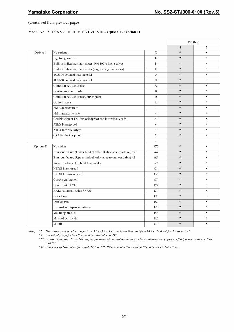
Model No.: STE9XX - I II III IV V VI VII VIII - Option I - Option II
Note) *2 The output current value ranges from 3.0 to 3.8 mA for the lower limit and from 20.8 to 21.8 mA for the upper limit.*5 Intrinsically safe for NEPSI cannot be selected with -D7.*17 In case “tantalum” is used for diaphragm material, normal operating conditions of meter body (process fluid) temperature is -10 to
+180°C*38 Either one of “digital output - code D5” or “HART communication - code D7” can be selected at a time.
Fill fluid4 7
Options I No options X a a
Lightning arrester L a a
Built-in indicating smart meter (0 to 100% liner scales) P a a
Built-in indicating smart meter (engineering unit scales) R a a
SUS304 bolt and nuts material W a a
SUS630 bolt and nuts material U a a
Corrosion-resistant finish A a a
Corrosion-proof finish B a a
Corrosion-resistant finish, silver paint D a a
Oil free finish K a a
FM Explosionproof 3 a a
FM Intrinsically safe 4 a a
Combination of FM Explosionproof and Intrinsically safe 5 a a
ATEX Flameproof 6 a a
ATEX Intrinsic safety 7 a a
CSA Explosion-proof 8 a a
-
Options II No option XX a a
Burn-out feature (Lower limit of value at abnormal condition) *2 A4 a a
Burn-out feature (Upper limit of value at abnormal condition) *2 A5 a a
Water free finish (with oil free finish) A7 a a
NEPSI Flameproof C1 a a
NEPSI Intrinsically safe C2 a a
Custom calibration C7 a a
Digital output *38 D5 a a
HART communication *5 *38 D7 a a
One elbow E1 a a
Two elbows E2 a a
External zero/span adjustment E5 a a
Mounting bracket E9 a a
Material certificate H2 a a
SI unit U1 a a

No. SS2-STJ300-0100 (Rev.5) Yamatake Corporation
- 28 -
ST3000 series 900 electric difference pressure transmitterModel STE929 / STE930 (Remote-sealed diaphragm type)Extended diaphragm 4 inches (100 mm)for high-temperature / vacuum, high-temperature / high-vacuum serviceModel No.: STE9XX - I II III IV V VI VII VIII - Option I - Option II
(Continued)
Basic Model No.
Measuring span2.5 to 100 kPa (250 to 10,160 mmH2O) STE929
Extended diaphragm flange type: 4 inches (100 mm)35 to 700 kPa (0.35 to 7 kgf/cm2) STE930
SelectionCode
Fill fluid codeI Fill fluid Flange type Fill fluid 4 7
STE929Extended diaphragm4 inches (100 mm)
For high-temperature / vacuum service(Silicone oil)
4
For high-temperature / high-vacuum service(Silicone oil)
7
STE930Extended diaphragm4 inches (100 mm)
For high-temperature / vacuum service(Silicone oil)
4
For high-temperature / high-vacuum service(Silicone oil)
7
II Flange standard ANSI flange A a a
JIS flange J a a
JPI flange P a a
III Flange type & rating
JIS 10K, ANSI/JPI 150 (RF) equivalent A a a
JIS 20K, ANSI/JPI 300 (RF) equivalent *23 B a a
JIS 30K, ANSI/JPI 600 (RF) equivalent *20 *24 C a a
IV Flange material Carbon Steel 1 a a
SUS304 7 a a
SUS316 2 a a
SUS316L 8 a a
V Material of wetted parts SUS316 (Diaphragm: SUS316L, others: SUS316) 2 a a
SUS316L (Diaphragm: SUS316L, others: SUS316L) *20 *23 8 a a
VI Finish of gasket face Standard (JIS Ra3.2 (12.5S)) J a a
VII Length of extended Parts
L = 50 mm (4 inches / 100 mm) *24 09 a a
L = 100 mm (4 inches / 100 mm) *24 14 a a
L = 150 mm (4 inches / 100 mm) *24 19 a a
L = 200 mm (4 inches / 100 mm) *23 *24 24 a a
L = 250 mm (4 inches / 100 mm) *23 *24 29 a a
L = 300 mm (4 inches / 100 mm) *23 *24 34 a a
VIII Length of capillary tube 2 m 2 a a
3 m 3 a a
4 m 4 a a
5 m 5 a a
6 m 6 a a
7 m 7 a a
8 m 8 a a
9 m 9 a a
10 m A a a

Yamatake Corporation No. SS2-STJ300-0100 (Rev.5)
- 29 -
(Continued from previous page)
Model No.: STE9XX - I II III IV V VI VII VIII - Option I - Option II
Note) *2 The output current value ranges from 3.0 to 3.8 mA for the lower limit and from 20.8 to 21.8 mA for the upper limit.*5 Intrinsically safe for NEPSI cannot be selected with -D7*15 Only available for Material of wetted parts: “SUS316” and “SUS316L”*20 In case “JIS 30K” is used for flange type and rating and in case “SUS316L” is used for flange material, not available for
the extended diaphragm type.*23 In case “ANSI/JPI 300” is used for flange type and rating, not available for length of extended parts: 200/250/300mm.*24 In case of “ANSI/JPI 600” is used for flange type and rating, not available for the extended diaphragm flange type.*38 Either one of “digital output - code D5” or “HART communication - code D7” can be selected at a time.
Fill fluid code4 7
Options I No options X a a
Lightning arrester L a a
Built-in indicating smart meter (0 to 100% liner scales) P a a
Built-in indicating smart meter (engineering unit scales) R a a
SUS304 bolt and nuts material W a a
SUS630 bolt and nuts material U a a
Corrosion-resistant finish A a a
Corrosion-proof finish B a a
Corrosion-resistant finish, silver paint D a a
Oil free finish K a a
FM Explosionproof 3 a a
FM Intrinsically safe 4 a a
Combination of FM Explosionproof and Intrinsically safe 5 a a
ATEX Flameproof 6 a a
ATEX Intrinsic safety 7 a a
CSA Explosion-proof 8 a a
-
Options II No option XX a a
Burn-out feature (Lower limit of value at abnormal condition) *2 A4 a a
Burn-out feature (Upper limit of value at abnormal condition) *2 A5 a a
Water free finish (with oil free finish) A7 a a
NEPSI Flameproof C1 a a
NEPSI Intrinsically safe C2 a a
Custom calibration C7 a a
Digital output *38 D5 a a
HART communication *5 *38 D7 a a
One elbow E1 a a
Two elbows E2 a a
External zero/span adjustment E5 a a
Mounting bracket E9 a a
Material certificate H2 a a
SI unit U1 a a
No. SS2-STJ300-0100 (Rev.5) Yamatake Corporation
- 30 -
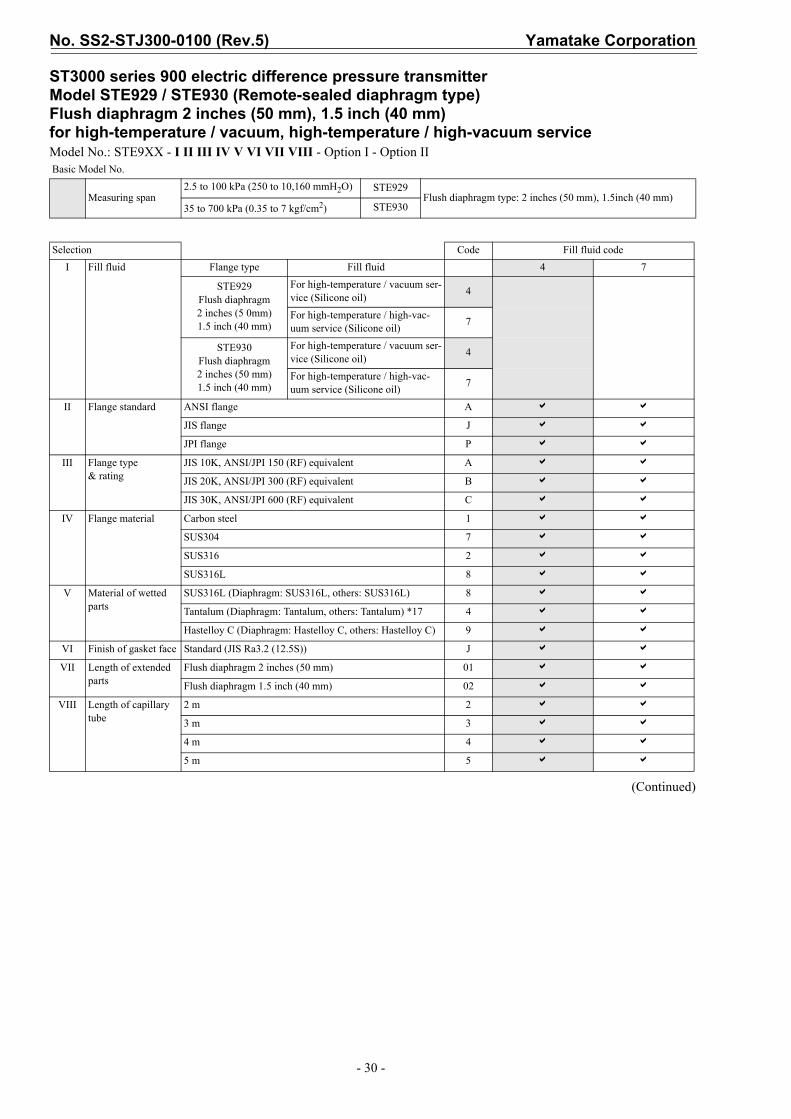
ST3000 series 900 electric difference pressure transmitterModel STE929 / STE930 (Remote-sealed diaphragm type)Flush diaphragm 2 inches (50 mm), 1.5 inch (40 mm)for high-temperature / vacuum, high-temperature / high-vacuum serviceModel No.: STE9XX - I II III IV V VI VII VIII - Option I - Option II
(Continued)
Basic Model No.
Measuring span2.5 to 100 kPa (250 to 10,160 mmH2O) STE929
Flush diaphragm type: 2 inches (50 mm), 1.5inch (40 mm)35 to 700 kPa (0.35 to 7 kgf/cm2) STE930
Selection Code Fill fluid codeI Fill fluid Flange type Fill fluid 4 7
STE929Flush diaphragm2 inches (5 0mm)1.5 inch (40 mm)
For high-temperature / vacuum ser-vice (Silicone oil) 4
For high-temperature / high-vac-uum service (Silicone oil) 7
STE930Flush diaphragm2 inches (50 mm)1.5 inch (40 mm)
For high-temperature / vacuum ser-vice (Silicone oil) 4
For high-temperature / high-vac-uum service (Silicone oil) 7
II Flange standard ANSI flange A a a
JIS flange J a a
JPI flange P a a
III Flange type & rating
JIS 10K, ANSI/JPI 150 (RF) equivalent A a a
JIS 20K, ANSI/JPI 300 (RF) equivalent B a a
JIS 30K, ANSI/JPI 600 (RF) equivalent C a a
IV Flange material Carbon steel 1 a a
SUS304 7 a a
SUS316 2 a a
SUS316L 8 a a
V Material of wetted parts
SUS316L (Diaphragm: SUS316L, others: SUS316L) 8 a a
Tantalum (Diaphragm: Tantalum, others: Tantalum) *17 4 a a
Hastelloy C (Diaphragm: Hastelloy C, others: Hastelloy C) 9 a a
VI Finish of gasket face Standard (JIS Ra3.2 (12.5S)) J a a
VII Length of extended parts
Flush diaphragm 2 inches (50 mm) 01 a a
Flush diaphragm 1.5 inch (40 mm) 02 a a
VIII Length of capillary tube
2 m 2 a a
3 m 3 a a
4 m 4 a a
5 m 5 a a

Yamatake Corporation No. SS2-STJ300-0100 (Rev.5)
- 31 -
(Continued from previous page)
Model No.: STE9XX - I II III IV V VI VII VIII - Option I - Option II
Note) *2 The output current value ranges from 3.0 to 3.8 mA for the lower limit and from 20.8 to 21.8 mA for the upper limit.*5 Intrinsically safe for NEPSI cannot be selected with -D7.*17 In case “Tantalum” is used for diaphragm material, and in case of “for high-temperature service”, normal operating conditions of meter
body (process fluid) temperature is -10 to +180°C.*38 Either on of “digital output - code D5” or “HART communication - code D7” can be selected at a time.
CodeFill fluid code
4 7Options I No options X a a
Lightning arrester L a a
Built-in indicating smart meter (0 to 100% liner scales) P a a
Built-in indicating smart meter (engineering unit scales) R a a
SUS304 bolt and nuts material W a a
SUS630 bolt and nuts material U a a
Corrosion-resistant finish A a a
Corrosion-proof finish B a a
Corrosion-resistant finish, silver paint D a a
Oil free finish K a a
FM Explosionproof 3 a a
FM Intrinsically safe 4 a a
Combination of FM Explosionproof and Intrinsically safe 5 a a
ATEX Flameproof 6 a a
ATEX Intrinsic safety 7 a a
CSA Explosion-proof 8 a a
-
Options II No option XX a a
Burn-out feature (Lower limit of value at abnormal condition) *2 A4 a a
Burn-out feature (Upper limit of value at abnormal condition) *2 A5 a a
Water free finish (with oil free finish) A7 a a
NEPSI Flameproof C1 a a
NEPSI Intrinsically safe C2 a a
Custom calibration C7 a a
Digital output *38 D5 a a
HART communication *5 *38 D7 a a
One elbow E1 a a
Two elbows E2 a a
External zero/span adjustment E5 a a
Mounting bracket E9 a a
Material certificate H2 a a
SI unit U1 a a

No. SS2-STJ300-0100 (Rev.5) Yamatake Corporation
- 32 -
ST3000 series 900 electric difference pressure transmitterModel STE929 / STE930 (Remote-sealed diaphragm type)Extended diaphragm 3 inches (80 mm), 2 inches (50 mm)for high-temperature / vacuum, high-temperature / high-vacuum serviceModel No.: STE9XX - I II III IV V VI VII VIII - Option I - Option II
(Continued)
Basic Model No.
Measuring span2.5 to 100 kPa (250 to 10,160 mmH2O)
35 to 700 kPa (0.35 to 7 kgf/cm2)
STE929 Extended diaphragm type:3 inches (80 mm), 2 inches (50 mm)STE930
Selection Code Fill fluid codeI Fill fluid Flange type Fill fluid 4 7
STE929Extended diaphragm
3 inches (80 mm) 2 inches (50 mm)
For high-temperature service(Silicone oil) 4
For high-temperature high-vacuum ser-vice (silicone oil) 7
STE930Extended diaphragm
3 inches (80 mm)2 inches (50 mm)
For high-temperature service(Silicone oil) 4
For high-temperature high-vacuum ser-vice (silicone oil) 7
II Flange standard ANSI flange A a a
JIS flange J a a
JPI flange P a a
III Flange type & rating
JIS 10K, ANSI/JPI 150 (RF) equivalent A a a
JIS 20K, ANSI/JPI 300 (RF) equivalent B a a
JIS 30K, ANSI/JPI 600 (RF) equivalent *24 C a a
IV Flange material Carbon Steel 1 a a
SUS304 7 a a
SUS316 2 a a
SUS316L 8 a a
V Material of wetted parts SUS316 (Diaphragm: SUS316L, others: SUS316) 2 a a
SUS316L (Diaphragm: SUS316L, others: SUS316L) 8 a a
VI Finish of gasket face Standard (JIS Ra3.2 (12.5S)) J a a
VII Length of extended parts L = 50 mm (3 inches / 80 mm) *24 05 a a
L = 100 mm (3 inches / 80 mm) *24 10 a a
L = 150 mm (3 inches / 80 mm) *24 15 a a
L = 50 mm (2 inches / 50 mm) *24 06 a a
L = 100 mm (2 inches / 50 mm) *24 11 a a
L = 150 mm (2 inches / 50 mm) *24 16 a a
VIII Length of capillary tube 2 m 2 a a
3 m 3 a a
4 m 4 a a
5 m 5 a a

Yamatake Corporation No. SS2-STJ300-0100 (Rev.5)
- 33 -
(Continued from previous page)
Model No.: STE9XX - I II III IV V VI VII VIII - Option I - Option II
Note) *2 The output current value ranges from 3.0 to 3.8 mA for the lower limit and from 20.8 to 21.8 mA for the upper limit.*5 Intrinsically safe for NEPSI cannot be selected with -D7.*24 In case of “ANSI/JPI 600” is used for flange type and rating, not available for the extended diaphragm flange type.*38 Either on of “digital output - code D5” or “HART communication - code D7” can be selected at a time.
Code Fill fluid code4 7
Options I No options X a a
Lightning arrester L a a
Built-in indicating smart meter (0 to 100% liner scales) P a a
Built-in indicating smart meter (engineering unit scales) R a a
SUS304 bolt and nuts material W a a
SUS630 bolt and nuts material U a a
Corrosion-resistant finish A a a
Corrosion-proof finish B a a
Corrosion-resistant finish, silver paint D a a
Oil free finish K a a
FM Explosionproof 3 a a
FM Intrinsically safe 4 a a
Combination of FM Explosionproof and Intrinsically safe 5 a a
ATEX Flameproof 6 a a
ATEX Intrinsic safety 7 a a
CSA Explosion-proof 8 a a
-
Options II No option XX a a
Burn-out feature (Lower limit of value at abnormal condition) *2 A4 a a
Burn-out feature (Upper limit of value at abnormal condition) *2 A5 a a
Water free finish (with oil free finish) A7 a a
NEPSI Flameproof C1 a a
NEPSI Intrinsically safe C2 a a
Custom calibration C7 a a
Digital output *38 D5 a a
HART communication *5 *38 D7 a a
One elbow E1 a a
Two elbows E2 a a
External zero/span adjustment E5 a a
Mounting bracket E9 a a
Material certificate H2 a a
SI unit U1 a a

No. SS2-STJ300-0100 (Rev.5) Yamatake Corporation
- 34 -
DIMENSIONSModel STE929 / STE930 (for regular type and high-temperature service)
Flush diaphragm flange / Extended diaphragm flange
Note) 1. To prevent vibration, you are recommended to fasten the capillary tube mid-length.2. Select a gasket that will not contact the diaphragm after it is tightened.3. When the suppression in larger than one half of the measuring span, the higher pressure side and
the lower pressure side of the process connection end flange are opposite to those shown in the fig-ure above. When using the transmitter to measure liquid levels, connect at H and L marks on the meter body as shown in the right figure.
ME
TER
SIG
NE
LL
+ñ
ñ+
ñTEST+
Rotational lock
Terminal connection(M4 Screw)
M4 External ground screw
4-M8 ScrewsDepth 8For mounting
42.8
42.8
Field terminal
17.560
94
To H.P flange
CO
VER MUST BE KEPT
TIGH
TW
HILECIRCUITSAREA
LIV
E
%135
67.5
1/2NPT Plug
Meter (option)
14138.455266
Electrical conduit connection1/2NPT Internal thread
2in. pipe
200160
115
124 (w/ Meter)120 (w/o Meter)
Capillary tube length
Mounting bracket(optional)
See flangedimensional drawing
H LMeter body
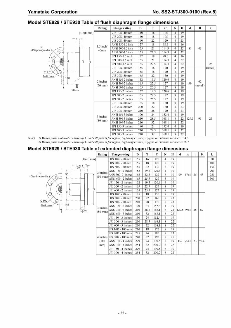
Yamatake Corporation No. SS2-STJ300-0100 (Rev.5)
- 35 -
Model STE929 / STE930 Table of flush diaphragm flange dimensions
Note) 1) Wetted parts material is Hastelloy C and Fill fluid is for reglon, high-temperature, oxygen, or chlorine service: B=432) Wetted parts material is Hastelloy C and Fill fluid is for reglon, high-temperature, oxygen, or chlorine service: t=26.7
Model STE929 / STE930 Table of extended diaphragm flange dimensions
Rating Flange rating D T C N H d B t[Unit: mm]
1.5 inch/40mm
JIS 10K-40 mm 140 16 105 4 19
81 43
25 (note2)
JIS 20K-40 mm 140 18 105 4 19JIS 30K-40 mm 160 22 120 4 23
ANSI 150-1.5 inch 127 18 98.6 4 16ANSI 300-1.5 inch 155 21 114.3 4 22ANSI 600-1.5 inch 155 22.5 114.3 4 22JPI 150-1.5 inch 127 18 98.6 4 16JPI 300-1.5 inch 155 21 114.3 4 22JPI 600-1.5 inch 155 22.5 114.3 4 22
2 inches(50 mm)
JIS 10K-50 mm 155 16 120 4 19
99 62 (note1)
JIS 20K-50 mm 155 18 120 8 19JIS 30K-50 mm 165 22 130 8 19
ANSI 150-2 inches 152 19.5 120.6 4 19ANSI 300-2 inches 165 22.5 127 8 19ANSI 600-2 inches 165 25.5 127 8 19JPI 150-2 inches 152 19.5 120.6 4 19JPI 300-2 inches 165 22.5 127 8 19JPI 600-2 inches 165 25.5 127 8 19
3 inches(80 mm)
JIS 10K-80 mm 185 18 150 8 19
129.5 95 25
JIS 20K-80 mm 200 22 160 8 23JIS 30K-80 mm 210 28 170 8 23
ANSI 150-3 inches 190 24 152.4 4 19ANSI 300-3 inches 210 28.5 168.1 8 22ANSI 600-3 inches 210 32 168.1 8 22JPI 150-3 inches 190 24 152.4 4 19JPI 300-3 inches 210 28.5 168.1 8 22JPI 600-3 inches 210 32 168.1 8 22
Rating Flange rating D T C N H d A t B L[Unit: mm]
2 inches(50 mm)
JIS 10K - 50 mm 155 16 120 4 19
99 47±1 25 43
50JIS 20K - 50 mm 155 18 120 8 19 100JIS 30K - 50 mm 165 22 130 8 19 150
ANSI 150 - 2 inches 152 19.5 120.6 4 19 200ANSI 300 -2 inches 165 22.5 127 8 19 250ANSI 600 - 2 inches 165 25.5 127 8 19 300JPI 150 - 2 inches 152 19.5 120.6 4 19JPI 300 - 2 inches 165 22.5 127 8 19JPI 600 - 2 inches 165 25.5 127 8 19
3 inches(80 mm)
JIS 10K - 80 mm 185 18 150 8 19
129.5 69±1 25 62
JIS 20K - 80 mm 200 22 160 8 23JIS 30K - 80 mm 210 28 170 8 23
ANSI 150 - 3 inches 190 24 152.4 4 19ANSI 300 - 3 inches 210 28.5 168.1 8 22ANSI 600 - 3 inches 210 32 168.1 8 22JPI 150 - 3 inches 190 24 152.4 4 19JPI 300 - 3 inches 210 28.5 168.1 8 22JPI 600 - 3 inches 210 32 168.1 8 22
4 inches(100 mm)
JIS 10K - 100 mm 210 18 175 8 19
157 95±1 23 90.4
JIS 20K - 100 mm 225 24 185 8 23JIS 30K - 100 mm 240 32 195 8 25ANSI 150 - 4 inches 229 24 190.5 8 19ANSI 300 - 4 inches 254 32 200.2 8 22JPI 150 - 4 inches 229 24 190.5 8 19JPI 300 - 4 inches 254 32 200.2 8 22
B(Diaphragm dia.)
C P.CN-H hole
t T
Dd
148
20
C P.C
N-H hole
20
t20
50
d
148
A D
TL
B(Diaphragm dia.)
