st75 information sheets/flowmeters/st… · 1/4″ tubing tee with compression fittings for use...
TRANSCRIPT

© Copyright 2009 Fluid Components International LLC. All rights reserved. Subject to change without notice.Doc. No. 01SA011466B
1755 La Costa Meadows DriveSan Marcos, California 92078 USA760-744-6950 / 800-854-1993 Fax: 760-736-6250 www.fluidcomponents.com
Order Information Sheet (OIS)
ST75 Air/Gas Flow Meter
Notes
1. Must use FCI’s AVAL program to determine letter code. AVAL is a custom flow meter optimizer program that considers gas medium, flow range, pipe size and other conditions to determine best calibration and supplies. FCI letter code to be used here. AVAL is available on-line at www.fluidcomponents.com or consult a local FCI representative/distributor.
2. Calibration accuracy is ±% of reading, ±0.5% of full scale.
3. Fixed cable length with instrument calibrated together as a matched set. Cable may be coiled but not cut.
Certified Material Test Report (CMTR) not available with ST75, see ST75V if required.
INSTRUCTIONS: To order an ST75, please fill in each numbered block above with the appropriate code from the categories below. Once you have determined all the specifications, contact an FCI representative or FCI directly for price information or additional options not shown. Consult FCI on the cost of special data and documentation. Final acceptance of the part number is subject to FCI’s approval.
ST75- …
Block No. 1 2 3 4 5 6 7
Options and Accessories
Part Number Description Part Number Description019819-01 Software Interface Package for PDA/PalmOS DM10-KIT1 Panel Mount Kit for DM10020802-01 PDA, Palm® model TungstenTM E2 DM10-KIT2 2″ (52 mm) Pipe Mount Kit for DM10 (Stainless steel)FC88 Portable Hand-held Communicator DM15 Digital Display/Readout, LED 115/230 Vac powered014108-02 PC Interface Communications Kit, For RS232 serial port connection DM15-ALM Same as DM-15 with user programmable alarm limit, relay outputDM10-N Digital Display/Readout, LCD, 4-20mA loop powered DM20 Digital Display Readout, 8-digit LCD Pulse totalizer/counterDM10-FC DM10 with FM and CSA approvals
Base Unit, Enclosure Style (Enclosures: all aluminum, NEMA 4X/IP67 rated, epoxy coated) (Block 1) CodeBlind, Integral Transmitter, with two 1/2″ FNPT cable entries 1Integral Transmitter with Local Digital Display, with two 1/2" FNPT cable entries 2Remote Transmitter with two 1/2″ FNPT cable entries and with Digital Display (specify cable length in Block 7) 4Blind, Integral Transmitter, with two M20x1.5 cable entries AIntegral Transmitter with Local Digital Display, with two M20x1.5 cable entries BRemote Transmitter with two M20x1.5 cable entries and with Digital Display (specify cable length in Block 7) C
Power Supply (Block 3) Code
DC; 18 - 36 V 1
AC; 85 - 265 V, 50/60 Hz 2Line Size and Process Connection (Block 4) Tee Body Length Code
1/4″ FNPT, 150 lb pipe tee 1.54″ [39,12 mm] A1/2″ FNPT, 150 lb pipe tee 2.28″ [57,91 mm] B3/4″ FNPT, 150 lb pipe tee 2.56″ [65,02 mm] C1″ FNPT, 150 lb pipe tee 2.92″ [74,17 mm] D1 1/2″ FNPT, 150 lb pipe tee 3.82″ [97,03 mm] E2″ FNPT, 150 lb pipe tee 4.66″ [118,40 mm] F1/4″ Tubing Tee with Compression Fittings for use with 1/4″ Tubing 2.34″ [59,44 mm] G1/2″ Tubing Tee with Compression Fittings for use with 1/2″ Tubing 2.84″ [72,14 mm] H1″ Tubing Tee with Compression Fittings for use with 1″ Tubing 3.86″ [98,04 mm] JGas Medium and System Calibration in Actual Tee Fitting 1 (Block 5) Code
Air BAir Equivalence (Oxygen, Chlorine, Ammonia, etc.) CNitrogen, Helium, Argon, CO2, Compressed Air EHydrocarbons (e.g. Natural Gas, Ethane, Methane, Propane, Ethylene, Propylene, Mixed) FAir, Compressed Air HAir Equivalence (e.g. Oxygen, Chlorine, Ammonia, etc.) JNitrogen, Argon KCO2, Ethylene, Ethane LPropane, Propylene MButane, Pentane NMethane, Helium, Natural Gas PCalibration 2 and Calibration Temperature Conditions (Block 6) Code
Standard 2% Calibration and Conditions +40 °F to 100 °F/ [4 °C to 38 °C] 0Standard 2% Calibration and Extended Temperature Compensation 0 °F to 250 °F [-18 °C to 121 °C] AHigh Accuracy 1% Calibration and Standard Conditions +40 °F to 100 °F [+4 °C to 38 °C] MHigh Accuracy 1% Calibration and Extended Temperature Compensation 0 °F to 250 °F [-18 °C to 121 °C] NInterconnecting Cable Length for Remote Configurations 3 (Block 7) Code
Not required (specify with integral configurations) 010′ [3 meters] A25′ [7,6 meters] B50′ [15 meters] CCustom length. (Cannot exceed 50′ [15 meters]) W
Pipe Installation, Display/Transmitter Mounting Orientation and Flow Direction (Block 2)
Horizontal Pipe Code Vertical Pipe CodeTop mount, display facing forward, flow left-to-right F Side mount left, display facing forward, flow up MTop mount, display facing forward, flow right-to-left G Side mount right, display facing forward, flow up NSide mount, display facing up, flow left-to-right H Side mount left, display facing forward, flow down PSide mount, display facing up, flow right-to-left J Side mount right, display facing forward, flow down RSide mount, display facing down, flow left-to-right K
For visual representation, refer to FCI drawing number 020943Side mount, display facing down, flow right-to-left L

ST75V Mass Flow Meter with Vortab® Flow Conditioners
Precision Mass Flow Meters Compatible with LineSizes from 1/4” to 2” [6 to 51mm] for Industrialand Commercial Process Gases
Vortab Flow Conditioners
ST75V Specifications
ST75V Specifications
Process Connections: Choice of Female NPT, Male NPT, ANSI flanges, DIN flangesMedia Compatibility: Air, compressed air, nitrogen, oxygen, argon, CO2, ozone, other inert gases, natural gas and other hydrocarbon gases, hydrogen.Accuracy: ±1% of reading, ±0.5% full scaleRepeatability: ±0.5%Temperature Compensation:
Standard: 40 °F to 100 °F [4 °C to 38 °C]Optional: 0 °F to 250 °F [ -18 °C to 121 °C]
Turndown Ratio: 10:1 to 100:1Agency Approvals:
FM/CSA: Class 1, Div. 1, Groups B,C,D; Class 1, Div. 2, Groups A-D ATEX/IECEx: Zone 1, II 2 G Ex d IIC T6…T3; II 2 D Ex tD A21, IP67 T90°…T300°
Element Materials of Construction: All-welded 316 Stainless Steel withHastelloy-C thermowells.Enclosure: NEMA 4X [IP67], aluminum, dual conduit ports with either ½ inch NPT or M20x1.5 entries. Epoxy coated.Output Signal:
Standard: (2) 4-20 mA, user assignable to flow rate and/or temperature (1) 0-1000 Hz pulse for total flow
Maximum Operating Pressure: 240 psi [16.5 bar(g)]Input Power:
DC: 18 Vdc to 36 Vdc (6 Watts maximum)AC: 85 Vdc to 265 Vac 85 to 265 Vac (12 Watts maximum) (CE approval for 100 Vac to 240 Vac)
Operating Temperature Range: 0 °F to 140 °F [ -18 °C to 60 °C]Digital Display (Optional): Two-line x 16 characters LCD. Displays measured value and engineering units. Top line assigned to flow rate. Second line is user assignable to temperature reading, as flow totalizer or alternating. Display can be rotated in 90° increments for optimum viewing orientation.
For installations with inadequate straight-run or obstructed flows that prevent a fully developed profile for accurate flow measurement with the standard ST75, the Model ST75”V” provides the solution. FCI’s Model ST75V includes all of the features and functionality of the ST75 plus built-in Vortab flow conditioning. Vortab flow conditioners are the flow conditioning technology proven and recommended by flow measurement experts to eliminate both swirl and velocity profile distortions to ensure accurate flow measurement.
Vortab flow conditioners also are the lowest pressure loss solution of all flow conditioning techniques. FCI is the exclusive provider of Vortab flow conditioners for use with thermal mass flow meters such as the ST75V.
In applications with limited space for pipe straight-run or when obstructors such as valves, bends, couplings or any other disturber which alters the flow profile are present, the ST75V is the solution to ensure the highest accuracy and repeatability.
Female NPT
Male NPT
Flanged
Configuration DIM A Pipe Size
DIM B Top to Flow CL
DIM C Flow CL to Bottom
DIM D VMR Length
ST75V-XXXCE 1/4″ 5.50 [140] 0.38 [9,5] 5.00 [127]ST75V-XXXEE 1/2″ 5.69 [144,5] 0.57 [14] 7.50 [190,5]ST75V-XXXFE 3/4″ 6.45 [164] 0.69 [17,5] 9.00 [229]ST75V-XXXGE 1″ 6.44 [163,5] 0.88 [22] 9.00 [229]ST75V-XXXHE 1 1/2″ 6.42 [163] 1.25 [32] 13.50 [343]ST75V-XXXJE 2″ 6.43 [163] 1.50 [38] 18.00 [457]
Female NPT Configuration
Configuration DIM A Pipe Size
DIM B Top to Flow CL
DIM C Flow CL to Bottom
DIM D Tee Length
ST75V-XXXCN 1/4″ 5.50 [140] 0.38 [9,5] 5.00 [127]ST75V-XXXEN 1/2″ 5.69 [144,5] 0.42 [10,6] 7.50 [190,5]ST75V-XXXFN 3/4″ 6.45 [164] 0.51 [13] 9.00 [229]ST75V-XXXGN 1″ 6.44 [163,5] 0.65 [16,5] 9.00 [229]ST75V-XXXHN 1 1/2″ 6.42 [163] .95 [24] 13.50 [343]ST75V-XXXJN 2″ 6.43 [163] 1.19 [30] 18.00 [457]
Male NPT Configuration
Configuration DIM A Pipe Size
DIM B Top to Flow CL
DIM C Flow CL to Bottom
DIM D Tee Length
ST75V-XXXCF 1/4″ n/a n/a n/aST75V-XXXEF 1/2″ 5.69 [144,5] 1.75 [45] 7.50 [190,5]ST75V-XXXFF 3/4″ 6.45 [164] 1.94 [49] 9.00 [229]ST75V-XXXGF 1″ 6.44 [163,5] 2.12 [54] 9.00 [229]ST75V-XXXHF 1 1/2″ 6.42 [163] 2.50 [64] 13.50 [343]ST75V-XXXJF 2″ 6.43 [163] 3.00 [76] 18.00 [457]
Flanged Configuration
Page 1 of 2

ORDERING GUIDE: ST75V Mass Flow Meter with Vortab® Flow Conditioners
Visit FCI on the Worldwide Web: www.fluidcomponents.comHeadquarters: 1755 La Costa Meadows DriveSan Marcos, California 92078 USAPhone: 760-744-6950 Toll Free: 800-854-1993 Fax: 760-736-6250 European Office: Persephonestraat 3-01 5047 TT Tilburg, The NetherlandsPhone: 31-13-5159989 Fax: 31-13-5799036
FCI is ISO 9001:2000 and AS9100 Certified
Locally Represented By:
© Copyright 2009 by Fluid Components International LLC. All rights reserved. Manufactured in accordance with one or more of the following patents: US Patent Numbers: 4,929,088, 4,967,593, 4,981,368, 4,994,780, 5,111,692, 5,600,528, 5,780,737, 5,913,250, 6,208,254, 6,340,243, 6,628,202, 6,843,110, China Patent Number: ZL00815586.0. FCI is a registered trademark of Fluid Components International LLC. Information subject to change without notice.
Doc. No. 02MK011529D0409 0K
Base Unit, Enclosure Style (Block 1) Enclosures: All Aluminum, NEMA 4X/IP67 rated, epoxy coated Code
Blind, Integral Transmitter, with two 1/2″ FNPT cable entries 1
Integral Transmitter with Local Digital Display, with two 1/2″ FNPT cable entries 2
Remote Transmitter w/ two 1/2″ FNPT cable entries and w/Digital Display.(Specify cable length in Block 10) 4
Blind, Integral Transmitter, w/ two M20x1.5 cable entries A
Integral Transmitter with Local Digital Display, w/ two M20x1.5 cable entries B
Remote Transmitter w/ two M20x1.5 cable entries and w/Digital Display.(Specify cable length in Block 10) C
Gas Medium and System Calibration 2 (Block 8) Code
Air B
Air Equivalence (Oxygen, Chlorine, Ammonia, etc.) C
Nitrogen, Helium, Argon, CO2, Compressed Air E
Hydrocarbons (e.g. Natural Gas, Ethane, Methane, Propane, Ethylene, Propylene, Mixed) F
Hydrogen or hydrogen mixture G
Air, Compressed Air H
Air Equivalence (e.g. Oxygen, Chlorine, Ammonia, etc.) J
Nitrogen, Argon K
CO2, Ethylene, Ethane L
Propane, Propylene M
Butane, Pentane N
Methane, Helium, Natural Gas P
Hydrogen R
Calibration 3 and Calibration Temperature Conditions (Block 9) Code
High Accuracy 1% Calibration and Standard Conditions +40 °F to 100 °F [+4 °C to 38 °C] w/Vortab Q
High Accuracy 1% Calibration and Extended Temperature Compensation 0 °F to 250 °F [-18 °C to 121 °C] w/Vortab T
Other, Agency approved,customer specified W
Interconnecting Cable Length for Remote Configurations 4 (Block 10) Code
Not required (Specify with integral configuations) 0
10′ [3 meters] A
25′ [7,6 meters] B
50′ [15 meters] C
Custom length (Cannot exceed 50 ′ [15 meters]) W
Part Number Description
019819-01 Software Interface Package for PDA/PalmOS
020802-01 PDA, Palm® model TungstenTM E2
FC88 Portable Hand-held Communicator
014108-02 PC Interface Communications Kit, For RS232 serial port connection
DM10-N Digital Display/Readout, LCD, 4-20 mA loop pow
DM10-FC DM10 with FM and CSA approvals
DM10-KIT1 Panel Mount Kit for DM10
DM10-KIT2 2 inch (52 mm) Pipe Mount Kit for DM10 (Stainless steel)
DM15 Digital Display/Readout, LED 115/230 Vac powered
DM15-ALM Same as DM-15 with user programmable alarm limit, relay output
DM20 Digital Display Readout, 8-digit LCD Pulse totalizer/counter
Optional Accessories
Power Supply (Block 3) Code
DC; 18 - 36 V 1
AC; 85 - 265 V, 50/60 Hz 2
Line Size (Block 4) Code
1/4″ (Available only with NPT, Block 5 must be Code E or N) 5 C
1/2″ E
3/4″ F
1″ G
1-1/2″ H
2″ J
Process Connection Type (Block 5) Code
Female NPT E
Male NPT N
Flanged, #150 CLASS F
Other; agency approved, customer specified(If selected, Block 6 and 7 which follow must also be Code WW only) W
Process Connection Size, Material, Rating, Finish Details (Block 6 & 7) Code
1/4″ NPT (must be selected if Block 4 is Code C) Q0
1/2″ NPT H0
3/4″ NPT T0
1″ NPT 10
1-1/2″ NPT B0
2″ NPT 20
1/2″ ANSI flanged 150 lb RF ANSI 16.5, 316L Stainless steel HG
3/4″ ANSI flanged 150 lb RF ANSI 16.5, 316L Stainless steel TG
1″ ANSI flanged 150 lb RF ANSI 16.5, 316L Stainless steel 1G
1-1/2″ ANSI flanged 150 lb RF ANSI 16.5, 316L Stainless steel BG
2″ ANSI flanged 150 lb RF ANSI 16.5, 316L Stainless steel 2G
DN15 DIN flanged PN40, Form C per DIN2526 or Form B1 per DIN EN1092-1 in 316L ss D2
DN25 DIN flanged PN40, Form C per DIN2526 or Form B1 per DIN EN1092-1 in 316L ss E2
DN40 DIN flanged PN40, Form C per DIN2526 or Form B1 per DIN EN1092-1 in 316L ss G2
DN50 DIN flanged PN16, Form C per DIN2526 or Form B1 per DIN EN1092-1 in 316L ss J2
Other; agency approved, customer specified WW
Model ST75V-Block No. 1 2 3 4 5 6 7 8 9 10
Notes
2 . Must use FCI’s AVAL program to determine letter code. AVAL is a custom flow meter optimizer program which considers gas medium, flow range, pipe size and other conditions to determine best calibration and supplies FCI letter code to be used here. AVAL is available on-line at www.fluidcomponents.com or consult local FCI representative/distributor.
3. Calibration accuracy is ±% of reading, ±0.5% of full scale.
4. Fixed cable length with instrument calibrated together as a matched set. Cable may be coiled, but not cut.
5. Certified Material Test Report (CMTR) not available with ST75V 1/4″.
Pipe Installation, Display/Transmitter Mounting Orientation and Flow Direction (Block 2)
Horizontal Pipe Code Vertical Pipe CodeTop mnt, display face frwd, flow L-R F Side mnt L, display face frwd, flow up MTop mnt, display face frwd, flow R-L G Side mnt R, display face frwd, flow up NSide mnt, display face up, flow L-R H Side mnt L, display face frwd, flow down PSide mnt, display face up, flow R-L J Side mnt R, display face frwd, flow down RSide mnt, display face down, flow L-R K For visual representation, refer to FCI drawing
number 020943Side mnt, display face down, flow R-L L
© Copyright 2009 Fluid Components International LLC. All rights reserved. Subject to change without notice. Doc. No. 01SA011458C
1755 La Costa Meadows DriveSan Marcos, California 92078 USA760-744-6950 / 800-854-1993 Fax: 760-736-6250 www.fluidcomponents.com
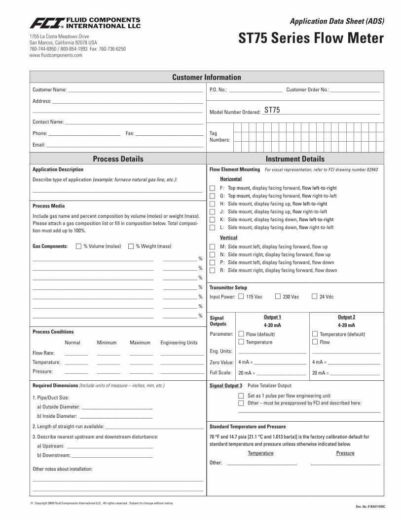
Application Data Sheet (ADS)
ST75 Series Flow Meter
Customer InformationCustomer Name: ____________________________________________________
Address: __________________________________________________________
__________________________________________________________________
Contact Name: ______________________________________________________
Phone: ____________________________ Fax: ___________________________
Email: ______________________________________________________________
P.O. No.: _____________________ Customer Order No.: ___________________
Model Number Ordered: ______________________________________________
Tag Numbers:
Process DetailsApplication Description
Describe type of application (example: furnace natural gas line, etc.) :
___________________________________________________________________
Process Media
Include gas name and percent composition by volume (moles) or weight (mass). Please attach a gas composition list or fill in composition below. Total composi-tion must add up to 100%.
Gas Components: c % Volume (moles) c % Weight (mass)
_______________________________________________ _____________ %
_______________________________________________ _____________ %
_______________________________________________ _____________ %
_______________________________________________ _____________ %
_______________________________________________ _____________ %
_______________________________________________ _____________ %
_______________________________________________ _____________ %
Process Conditions
Normal Minimum Maximum Engineering Units
Flow Rate: _________ _________ _________ _________________
Temperature: _________ _________ _________ _________________
Pressure: _________ _________ _________ _________________
Required Dimensions (Include units of measure – inches, mm, etc.)
1. Pipe/Duct Size:
a) Outside Diameter: ____________________________
b) Inside Diameter: _____________________________
2. Length of straight-run available: ______________________________________
3. Describe nearest upstream and downstream disturbance:
a) Upstream: __________________________________
b) Downstream: ________________________________
Other notes about installation:
____________________________________________________________________
____________________________________________________________________
Instrument DetailsFlow Element Mounting For visual representation, refer to FCI drawing number 02943
Horizontal
c F: Top mount, display facing forward, flow left-to-rightc G: Top mount, display facing forward, flow right-to-leftc H: Side mount, display facing up, flow left-to-rightc J: Side mount, display facing up, flow right-to-leftc K: Side mount, display facing down, flow left-to-rightc L: Side mount, display facing down, flow right-to-left
Vertical
c M: Side mount left, display facing forward, flow upc N: Side mount right, display facing forward, flow upc P: Side mount left, display facing forward, flow downc R: Side mount right, display facing forward, flow down
Transmitter Setup
Input Power: c 115 Vac c 230 Vac c 24 Vdc
Signal Outputs
Parameter:
Eng. Units:
Zero Value:
Full Scale:
Output 1 Output 2
4-20 mA
c Flow (default) c Temperature
__________________________
4 mA = ____________________
20 mA = ___________________
4-20 mA
c Temperature (default) c Flow
__________________________
4 mA = ____________________
20 mA = ___________________
Signal Output 3 Pulse Totalizer Output:
c Set as 1 pulse per flow engineering unit c Other – must be preapproved by FCI and described here: ________________________________________________________
Standard Temperature and Pressure
70 °F and 14.7 psia [21.1 °C and 1.013 bar(a)] is the factory calibration default for standard temperature and pressure unless otherwise indicated below.
Temperature Pressure
Other: ___________________________ ___________________________
ST75
