staad pro 2007 examples
DESCRIPTION
complete example problemsTRANSCRIPT

STAAD.Pro 2007
BRITISH EXAMPLES MANUAL DAA037800-1/0001
A Bentley Solutions Center
www.reiworld.com
www.bentley.com/staad

STAAD.Pro 2007 is a suite of proprietary computer programs of Research Engineers, a
Bentley Solutions Center . Although every effort has been made to ensure the
correctness of these programs, REI will not accept responsibility for any mistake, error
or misrepresentation in or as a result of the usage of these programs.
Copyright attribution: ©2008, Bentley Systems, Incorporated. All rights reserved.
Trademark attribution: STAAD.Pro, STAAD.foundation, Section Wizard,
STAAD.Offshore and QSE are either registered or unregistered trademarks or
service marks of Bentley Systems, Incorporated or one of its direct or indirect
wholly-owned subsidiaries. Other brands and product names are trademarks of their
respective owners.
RELEASE 2007, Build 02
Published February, 2008

About STAAD.Pro
STAAD.Pro is a general purpose structural analysis and design program with
applications primarily in the building industry - commercial buildings, bridges and
highway structures, industrial structures, chemical plant structures, dams, retaining
walls, turbine foundations, culverts and other embedded structures, etc. The program
hence consists of the following facilit ies to enable this task.
1. Graphical model generation utilities as well as text editor based commands for
creating the mathematical model. Beam and column members are represented
using lines. Walls, slabs and panel type entities are represented using triangular
and quadrilateral finite elements. Solid blocks are represented using brick
elements. These utilities allow the user to create the geometry, assign properties,
orient cross sections as desired, assign materials like steel, concrete, timber,
aluminum, specify supports, apply loads explicitly as well as have the program
generate loads, design parameters etc.
2. Analysis engines for performing linear elastic and pdelta analysis, finite element
analysis, frequency extraction, response spectrum and time histor y analysis.
3. Design engines for code checking and optimization of steel, aluminum and timber
members. Reinforcement calculations for concrete beams, columns, slabs and
shear walls. Design of shear and moment connections for steel members.
4. Result viewing, result verification and report generation tools for examining
displacement diagrams, bending moment and shear force diagrams, beam, plate
and solid stress contours, etc.
5. Peripheral tools for activities like import and export of data from and to other
widely accepted formats, links with other popular softwares for niche areas like
reinforced and prestressed concrete slab design, footing design, steel connection
design, etc.
6. A library of exposed functions called OpenSTAAD which allows users to access
STAAD.Pro’s internal functions and routines as well as its graphical commands to
tap into STAAD’s database and link input and output data to third -party software
written using languages like C, C++, VB, VBA, FORTRAN, Java, Delphi, etc.
Thus, OpenSTAAD allows users to link in-house or third-party applications with
STAAD.Pro.

About the STAAD.Pro Documentation
The documentation for STAAD.Pro consists of a set of manuals as described below.
These manuals are normally provided only in the electronic format, with p erhaps some
exceptions such as the Getting Started Manual which may be supplied as a printed
book to first time and new-version buyers.
All the manuals can be accessed from the Help facilities of STAAD.Pro. Users who
wish to obtain a printed copy of the books may contact Research Engineers. REI also
supplies the manuals in the PDF format at no cost for those who wish to print them on
their own. See the back cover of this book for addresses and phone numbers.
Getting Started and Tutorials: This manual contains information on the contents of
the STAAD.Pro package, computer system requirements, installation process, copy
protection issues and a description on how to run the programs in the package.
Tutorials that provide detailed and step-by-step explanation on using the programs are
also provided.
Examples Manual: This book offers examples of various problems that can be solved
using the STAAD engine. The examples represent various structural analyses and
design problems commonly encountered by structural engineers.
Graphical Environment: This document contains a detailed description of the
Graphical User Interface (GUI) of STAAD.Pro. The topics covered include model
generation, structural analysis and design, result verification, and report generation.
Technical Reference Manual: This manual deals with the theory behind the
engineering calculations made by the STAAD engine. It also includes an explanation
of the commands available in the STAAD command file.
International Design Codes: This document contains information on the various
Concrete, Steel, and Aluminum design codes, of several countries, that are
implemented in STAAD.
The documentation for the STAAD.Pro Extension component(s) is available
separately.

i
Introduction The tutorials in the Getting Started Manual mention 2 methods of creating the STAAD input data. a. Using the facilities of the Graphical User Interface (GUI)
modelling mode b. Using the editor which comes built into the STAAD program Method (a) is explained in great detail in the various tutorials of that manual. The emphasis in this Examples manual is on creating the data using method (b). A number of examples, representing a wide variety of structural engineering problems, are presented. All the input needed is explained line by line to facilitate the understanding of the STAAD command language. These examples also illustrate how the various commands in the program are to be used together. Although a user can prepare the input through the STAAD GUI, it is quite useful to understand the language of the input for the following reasons: 1) STAAD is a large and comprehensive structural engineering
software. Knowledge of the STAAD language can be very useful in utilizing the large number of facilities available in the program. The Graphical User Interface can be used to generate the input file for even the most complex of structures. However, the user can easily make changes to the input data if he/she has a good understanding of the command language and syntax of the input.

ii 2) The input file represents the user's thought about what he/she
wants to analyze or design. With the knowledge of the STAAD command language, the user or any other person can verify the accuracy of the work.
The commands used in the input file are explained in Section 5 of the STAAD Technical Reference Manual. Users are urged to refer to that manual for a better understanding of the language. The procedure for creating the file using the built-in editor is explained further below in this section. Alternatively, any standard text editor such as Notepad or WordPad may also be used to create the command file. However, the STAAD.Pro command file editor offers the advantage of syntax checking as we type the commands. The STAAD.Pro keywords, numeric data, comments, etc. are displayed in distinct colors in the STAAD.Pro editor. A typical editor screen is shown below to illustrate its general appearance.

iii To access the built-in editor, first start the program and follow the steps explained in Sections 1.3 and 1.4 of the Getting Started manual.
You will then encounter the dialog box shown in the following figure. In this dialog box, choose Open STAAD Editor.

iv At this point, the editor screen will open as shown below.
Delete all the command lines displayed in the editor window and type the lines shown in bold in the various examples in this book (You don’t have to delete the lines if you know which to keep and where to fill in the rest of the commands). The commands may be typed in upper or lower case letters. For your convenience, the data for all the examples presented in this manual are supplied to you along with the program CD. You will find them in the folder location X:\spro2007\staad\examp\uk where “X:” is the drive, and “spro2007” is the name of the installation folder if you happened to go with the default during installation. The example files are named in accordance with the order they appear in this manual, namely, examp01.std for example 1, examp08.std for example 8, and so on.

v The second part of this book contains a set of verification problems which compares the analytical results from the program with standard publications on the subject. They too are installed along with the examples. To view their contents in the editor, open the file you are interested in. Then, click on the STAAD editor icon, or, go to the Edit menu, and choose Edit Input Command File, as shown below.

vi A new window will open up with the data listed as shown here:
To exit the Editor, select the File | Exit menu option of the editor window (not the File | Exit menu of the main window behind the editor window).

Table of Contents
Part – I Example Problems
Example Problem No. 1 1
Example Problem No. 2 19
Example Problem No. 3 27
Example Problem No. 4 35
Example Problem No. 5 47
Example Problem No. 6 53
Example Problem No. 7 59
Example Problem No. 8 65
Example Problem No. 9 75
Example Problem No. 10 85
Example Problem No. 11 93
Example Problem No. 12 105
Example Problem No. 13 113
Example Problem No. 14 121
Example Problem No. 15 133
Example Problem No. 16 147
Example Problem No. 17 155
Example Problem No. 18 165
Example Problem No. 19 173
Example Problem No. 20 183
Example Problem No. 21 189

Example Problem No. 22 199
Example Problem No. 23 209
Example Problem No. 24 221
Example Problem No. 25 235
Example Problem No. 26 243
Example Problem No. 27 251
Example Problem No. 28 263
Example Problem No. 29 281
Part – II Verification Problems
Verification Problem No. 1 1
Verification Problem No. 2 3
Verification Problem No. 3 5
Verification Problem No. 4 9
Verification Problem No. 5 11
Verification Problem No. 6 15
Verification Problem No. 7 17
Verification Problem No. 8 19
Verification Problem No. 9 21
Verification Problem No. 10 23
Verification Problem No. 11 27
Verification Problem No. 12 31

PART – I
APPLICATION EXAMPLES


Description of Example Problems 1) Example problem No. 1 - Plane frame with steel design. After
one analysis, member selection is requested. Since member sizes change during the member selection, another analysis is done followed by final code checking to verify that the final sizes meet the requirements of the code based on the latest analysis results.
2) Example problem No. 2 - A floor structure (bound by global
X-Z axis) made up of steel beams is subjected to area load (i.e. load/area of floor). Load generation based on one-way distribution is illustrated in this example.
3) Example problem No. 3 - A portal frame type steel structure
is sitting on a concrete footing. The soil is to be considered as an elastic foundation.
4) Example problem No. 4 - This example is a typical case of a
load-dependent structure where the structural condition changes for different load cases. In this example, different bracing members are made inactive for different load cases. This is done to prevent these members from carrying any compressive forces.
5) Example problem No. 5 - This example demonstrates the
application of support displacement load (commonly known as sinking support) on a space frame structure.
6) Example problem No. 6 - This is an example of prestress
loading in a plane frame structure. It covers two situations: 1) The prestressing effect is transmitted from the member on which it is applied to the rest of the structure through the connecting members (known in the program as PRESTRESS load). 2) The prestressing effect is experienced by the member(s) alone and not transmitted to the rest of the structure (known in the program as POSTSTRESS load).

7) Example problem No. 7 - This example illustrates modelling of structures with OFFSET connections. Offset connections arise when the center lines of the connected members do not intersect at the connection point. The connection eccentricity is modeled through specification of MEMBER OFFSETS.
8) Example problem No. 8 - In this example, concrete design is
performed on some members of a space frame structure. Design calculations consist of computation of reinforcement for beams and columns. Secondary moments on the columns are obtained through the means of a P-Delta analysis.
9) Example problem No. 9 - A space frame structure in this
example consists of frame members and finite elements. The finite element part is used to model floor flat plates and a shear wall. Design of an element is performed.
10) Example problem No. 10 - A tank structure is modeled with
four-noded plate elements. Water pressure from inside is used as loading for the tank. Reinforcement calculations have been done for some elements.
11) Example problem No. 11 - Dynamic analysis (Response
Spectrum) is performed for a steel structure. Results of a static and dynamic analysis are combined. The combined results are then used for steel design.
12) Example problem No. 12 - This example demonstrates
generation of load cases for the type of loading known as a moving load. This type of loading occurs classically when the load-causing units move on the structure, as in the case of trucks on a bridge deck. The mobile loads are discretized into several individual immobile load cases at discrete positions. During this process, enormous number of load cases may be created resulting in plenty of output to be sorted. To avoid looking into a lot of output, the maximum force envelope is requested for a few specific members.
13) Example problem No. 13 - Calculation of displacements at
intermediate points of members of a plane frame is demonstrated in this example.

14) Example problem No. 14 - A space frame is analyzed for seismic loads. The seismic loads are generated using the procedures of the 1994 UBC Code. A P-Delta analysis is performed to obtain the secondary effects of the lateral and vertical loads acting simultaneously.
15) Example problem No. 15 - A space frame is analyzed for
loads generated using the built-in wind and floor load generation facilities.
16) Example problem No. 16 - Dynamic Analysis (Time History)
is performed for a 3 span beam with concentrated and distributed masses. The structure is subjected to "forcing function" and "ground motion" loading. The maxima of the joint displacements, member end forces and support reactions are determined.
17) Example problem No. 17 - The usage of User Provided Steel Tables is illustrated in this example for the analysis and design of a plane frame.
18) Example problem No. 18 - This is an example which
demonstrates the calculation of principal stresses on a finite element.
19) Example problem No. 19 - This example demonstrates the
usage of inclined supports. The word INCLINED refers to the fact that the restraints at a joint where such a support is specified are along a user-specified axis system instead of along the default directions of the global axis system. STAAD offers a few different methods for assigning inclined supports, and we examine those in this example.
20) Example problem No. 20 - This example generates the
geometry of a cylindrical tank structure using the cylindrical coordinate system.
21) Example problem No. 21 - This example illustrates the
modeling of tension-only members using the MEMBER TENSION command.

22) Example problem No. 22 - A space frame structure is subjected to a sinusoidal loading. The commands necessary to describe the sine function are demonstrated in this example. Time History analysis is performed on this model.
23) Example problem No. 23 - This example illustrates the usage
of commands necessary to automatically generate spring supports for a slab on grade. The slab is subjected to various types of loading and analysis of the structure is performed.
24) Example problem No. 24 - This is an example of the analysis
of a structure modelled using “SOLID” finite elements. This example also illustrates the method for applying an “enforced” displacement on the structure.
25) Example problem No. 25 - This example demonstrates the
usage of compression-only members. Since the structural condition is load dependent, the PERFORM ANALYSIS command is specified once for each primary load case.
26) Example problem No. 26 - The structure in this example is a
building consisting of member columns as well as floors made up of beam members and plate elements. Using the master-slave command, the floors are specified to be rigid diaphragms for inplane actions but flexible for bending actions.
27) Example problem No. 27 - This example illustrates the usage
of commands necessary to apply the compression only attribute to automatically generated spring supports for a slab on grade. The slab is subjected to pressure and overturning loading. A tension/compression only analysis of the structure is performed.
28) Example problem No. 28 - This example demonstrates the
input required for obtaining the modes and frequencies of the skewed bridge. The structure consists of piers, pier-cap girders and a deck slab.
29) Example problem No. 29 - Analysis and design of a structure
for seismic loads is demonstrated in this example. The elaborate dynamic analysis procedure called time history analysis is used.

NOTES

NOTES

Example Problem 1 1
Example Problem No. 1
Plane frame with steel design. After one analysis, member selection is requested. Since member sizes change during the member selection, another analysis is done followed by final code checking to verify that the final sizes meet the requirements of the code based on the latest analysis results.

Part I - Application Examples Example Problem 1 2
Actual input is shown in bold lettering followed by explanation. STAAD PLANE EXAMPLE PROBLEM NO. 1
Every input has to start with the word STAAD. The word PLANE signifies that the structure is a plane frame structure and the geometry is defined through X and Y axes.
UNIT METER KN
Specifies the unit to be used. JOINT COORDINATES 1 0 0 ; 2 9 0 ; 3 0 6 ; 4 3 6 5 6 6 ; 6 9 6 ; 7 0 10.5 8 9 10.5 ; 9 2.25 10.5 ; 10 6.75 10.5 11 4.5 10.5 ; 12 1.5 11.4 ; 13 7.5 11.4 14 3 12.3 ; 15 6 12.3 ; 16 4.5 13.2
Joint number followed by X and Y coordinates are provided above. Since this is a plane structure, the Z coordinates need not be provided. Semicolon signs (;) are used as line separators to allow for input of multiple sets of data on one line.
MEMBER INCIDENCE 1 1 3 ; 2 3 7 ; 3 2 6 ; 4 6 8 ; 5 3 4 6 4 5 ; 7 5 6 ; 8 7 12 ; 9 12 14 10 14 16 ; 11 15 16 ; 12 13 15 ; 13 8 13 14 9 12 ; 15 9 14 ; 16 11 14 ; 17 11 15 18 10 15 ; 19 10 13 ; 20 7 9 21 9 11 ; 22 10 11 ; 23 8 10
Defines the members by the joints they are connected to. MEMBER PROPERTY BRITISH 1 3 4 TA ST UC356X368X129 ; 2 TA ST UC254X254X73 5 6 7 TA ST UB533X210X82 ; 8 TO 13 TA ST UB457X152X52 14 TO 23 TA ST UA100X100X8
Member properties are from the British steel table. The word ST stands for standard single section.

Example Problem 1 3
MEMB TRUSS 14 TO 23
The above command defines that members 14 through 23 are of type truss. This means that these members can carry only axial tension/compression and no moments.
MEMB RELEASE 5 START MZ
Member 5 has local moment-z (MZ) released at the start joint. This means that the member cannot carry any moment-z (i.e. strong axis moment) at node 3.
UNIT KN MMS CONSTANTS E 210. ALL DEN 76.977E-09 ALL POISSON STEEL ALL BETA 90.0 MEMB 3 4 UNIT METER
The CONSTANT command initiates input for material constants like E (modulus of elasticity), POISSON, etc. Length unit is changed from METER to MM to facilitate the input. The BETA command specifies that members 3 and 4 are rotated by 90 degrees around their own longitudinal axis. See section 1 of the Technical Reference Manual for the definition of the BETA angle.
SUPPORT 1 FIXED ; 2 PINNED
A fixed support is located at joint 1 and a pinned support at joint 2.

Part I - Application Examples Example Problem 1 4
PRINT MEMBER INFORMATION LIST 1 5 14 PRINT MEMBER PROPERTY LIST 1 2 5 8 14
The above PRINT commands are self-explanatory. The LIST option restricts the print output to the members listed.
LOADING 1 DEAD AND LIVE LOAD
Load case 1 is initiated followed by a title. SELFWEIGHT Y -1.0
One of the components of load case 1 is the selfweight of the structure acting in the global Y direction with a factor of -1.0. Since global Y is vertically upward, the factor of -1.0 indicates that this load will act downwards.
JOINT LOAD 4 5 FY -65. ; 11 FY -155.
Load 1 contains joint loads also. FY indicates that the load is a force in the global Y direction.
MEMB LOAD 8 TO 13 UNI Y -13.5 ; 6 UNI GY -17.5
Load 1 contains member loads also. GY indicates that the load is in the global Y direction while Y indicates local Y direction. The word UNI stands for uniformly distributed load. Loads are applied on members 6, and 8 to 13.
CALCULATE RAYLEIGH FREQUENCY
The above command at the end of load case 1, is an instruction to perform a natural frequency calculation based on the Rayleigh method using the data in the above load case.
LOADING 2 WIND FROM LEFT MEMBER LOAD 1 2 UNI GX 9.0 ; 8 TO 10 UNI Y -15.0

Example Problem 1 5
Load case 2 is initiated and contains several member loads. * 1/3 RD INCREASE IS ACCOMPLISHED BY 75% LOAD LOAD COMB 3 75 PERCENT DL LL WL 1 0.75 2 0.75
The above command identifies a combination load (case no. 3) with a title. The second line provides the load cases and their respective factors used for the load combination. Any line beginning with the * mark is treated as a comment line.
PERFORM ANALYSIS
This command instructs the program to proceed with the analysis. LOAD LIST 1 3
The above command activates load cases 1 and 3 only for the commands to follow. This also means that load case 2 will be made inactive.
PRINT MEMBER FORCES PRINT SUPPORT REACTION
The above PRINT commands are self-explanatory. Also note that all the forces and reactions will be printed for load cases 1 and 3 only.
PARAMETER CODE BRITISH NSF 0.85 ALL BEAM 1 ALL KY 1.2 MEMB 3 4 RATIO 0.9 ALL
The PARAMETER command is used to specify steel design parameters such as NSF, KY, etc. Information on these parameters can be obtained from the manual where the implementation of the code is explained. The BEAM parameter is specified to perform design at every 1/12th point along the member length. The RATIO

Part I - Application Examples Example Problem 1 6
parameter specifies that the ratio of actual loading over section capacity should not exceed 0.9.
SELECT ALL
The above command instructs the program to select the most economic section for ALL the members based on the results of the analysis.
GROUP MEMB 1 3 4 GROUP MEMB 5 6 7 GROUP MEMB 8 TO 13 GROUP MEMB 14 TO 23
Although the program selects the most economical section for all members, it is not always practical to use many different sizes in one structure. GROUPing is a procedure by which the cross section which has the largest value for the specified attribute, which in this case is the default and hence the AREA, from among the associated member list, is assigned to all members in the list. Hence, the cross sections for members 1, 3 and 4 are replaced with the one with the largest area from among the three.
PERFORM ANALYSIS
As a result of the selection and grouping, the member sizes are no longer the same as the ones used in the original analysis. Hence, it is necessary to reanalyze the structure using the new properties to get new values of forces in the members.
PARAMETER BEAM 1.0 ALL RATIO 1.0 ALL TRACK 1.0 ALL
A new set of values are now provided for the above parameters. The actual load to member capacity RATIO has been redefined as 1.0. The TRACK parameter tells the program to print out the design results to the intermediate level of descriptivity.

Example Problem 1 7
CHECK CODE ALL
With the above command, the latest member sizes with the latest analysis results are checked to verify that they satisfy the CODE specifications.
STEEL TAKE OFF
This command instructs the program to list the length and weight of all the different member sizes.
FINISH
This command terminates the STAAD run.

Part I - Application Examples Example Problem 1 8
**************************************************** * * * STAAD.Pro * * Version 2007 Build 02 * * Proprietary Program of * * Research Engineers, Intl. * * Date= * * Time= * * * * USER ID: * **************************************************** 1. STAAD PLANE EXAMPLE PROBLEM NO. 1 2. UNIT METER KN 3. JOINT COORDINATES 4. 1 0 0 ; 2 9 0 ; 3 0 6 ; 4 3 6 5. 5 6 6 ; 6 9 6 ; 7 0 10.5 6. 8 9 10.5 ; 9 2.25 10.5 ; 10 6.75 10.5 7. 11 4.5 10.5 ; 12 1.5 11.4 ; 13 7.5 11.4 8. 14 3 12.3 ; 15 6 12.3 ; 16 4.5 13.2 9. MEMBER INCIDENCE 10. 1 1 3 ; 2 3 7 ; 3 2 6 ; 4 6 8 ; 5 3 4 11. 6 4 5 ; 7 5 6 ; 8 7 12 ; 9 12 14 12. 10 14 16 ; 11 15 16 ; 12 13 15 ; 13 8 13 13. 14 9 12 ; 15 9 14 ; 16 11 14 ; 17 11 15 14. 18 10 15 ; 19 10 13 ; 20 7 9 15. 21 9 11 ; 22 10 11 ; 23 8 10 16. MEMBER PROPERTY BRITISH 17. 1 3 4 TA ST UC356X368X129 ; 2 TA ST UC254X254X73 18. 5 6 7 TA ST UB533X210X82 ; 8 TO 13 TA ST UB457X152X52 19. 14 TO 23 TA ST UA100X100X8 20. MEMB TRUSS 21. 14 TO 23 22. MEMB RELEASE 23. 5 START MZ 24. UNIT KN MMS 25. CONSTANTS 26. E 210. ALL 27. DEN 76.977E-09 ALL 28. POISSON STEEL ALL 29. BETA 90.0 MEMB 3 4 30. UNIT METER 31. SUPPORT 32. 1 FIXED ; 2 PINNED 33. PRINT MEMBER INFORMATION LIST 1 5 14 MEMBER INFORMATION ------------------ MEMBER START END LENGTH BETA JOINT JOINT (METE) (DEG) RELEASES 1 1 3 6.000 0.00 5 3 4 3.000 0.00 000001000000 14 9 12 1.172 TRUSS ************ END OF DATA FROM INTERNAL STORAGE ************ 34. PRINT MEMBER PROPERTY LIST 1 2 5 8 14

Example Problem 1 9 MEMBER PROPERTIES. UNIT - CM ----------------- MEMB PROFILE AX/ IZ/ IY/ IX/ AY AZ SZ SY 1 ST UC356X368X129 164.00 40250.00 14610.00 152.61 36.98 116.11 2263.78 792.73 2 ST UC254X254X73 93.10 11410.00 3908.00 57.62 21.85 65.07 898.07 306.99 5 ST UB533X210X82 105.00 47540.00 2007.00 51.52 50.72 49.61 1799.74 192.24 8 ST UB457X152X52 66.60 21370.00 645.00 21.37 34.18 29.90 950.20 84.65 14 ST UA100X100X8 15.60 60.54 235.86 3.33 5.33 5.33 15.55 33.36 ************ END OF DATA FROM INTERNAL STORAGE ************ 35. LOADING 1 DEAD AND LIVE LOAD 36. SELFWEIGHT Y -1.0 37. JOINT LOAD 38. 4 5 FY -65. ; 11 FY -155. 39. MEMB LOAD 40. 8 TO 13 UNI Y -13.5 ; 6 UNI GY -17.5 41. CALCULATE RAYLEIGH FREQUENCY 42. LOADING 2 WIND FROM LEFT 43. MEMBER LOAD 44. 1 2 UNI GX 9.0 ; 8 TO 10 UNI Y -15.0 45. * 1/3 RD INCREASE IS ACCOMPLISHED BY 75% LOAD 46. LOAD COMB 3 75 PERCENT DL LL WL 47. 1 0.75 2 0.75 48. PERFORM ANALYSIS P R O B L E M S T A T I S T I C S ----------------------------------- NUMBER OF JOINTS/MEMBER+ELEMENTS/SUPPORTS = 16/ 23/ 2 SOLVER USED IS THE IN-CORE ADVANCED SOLVER TOTAL PRIMARY LOAD CASES = 2, TOTAL DEGREES OF FREEDOM = 43 ZERO STIFFNESS IN DIRECTION 6 AT JOINT 9 EQN.NO. 22 LOADS APPLIED OR DISTRIBUTED HERE FROM ELEMENTS WILL BE IGNORED. THIS MAY BE DUE TO ALL MEMBERS AT THIS JOINT BEING RELEASED OR EFFECTIVELY RELEASED IN THIS DIRECTION. ZERO STIFFNESS IN DIRECTION 6 AT JOINT 10 EQN.NO. 25 ZERO STIFFNESS IN DIRECTION 6 AT JOINT 11 EQN.NO. 28 ********************************************************** * * * RAYLEIGH FREQUENCY FOR LOADING 1 = 3.48726 CPS * * MAX DEFLECTION = 2.54544 CM GLO X, AT JOINT 7 * * * ********************************************************** 49. LOAD LIST 1 3 50. PRINT MEMBER FORCES

Part I - Application Examples Example Problem 1 10
MEMBER END FORCES STRUCTURE TYPE = PLANE ----------------- ALL UNITS ARE -- KN METE (LOCAL ) MEMBER LOAD JT AXIAL SHEAR-Y SHEAR-Z TORSION MOM-Y MOM-Z 1 1 1 239.74 -7.78 0.00 0.00 0.00 -72.75 3 -232.17 7.78 0.00 0.00 0.00 26.06 3 1 179.67 85.56 0.00 0.00 0.00 334.51 3 -173.99 -45.06 0.00 0.00 0.00 57.37 2 1 3 150.36 -22.47 0.00 0.00 0.00 -26.06 7 -147.13 22.47 0.00 0.00 0.00 -75.07 3 3 128.85 -0.17 0.00 0.00 0.00 -57.37 7 -126.43 30.54 0.00 0.00 0.00 -11.73 3 1 2 258.36 0.00 -7.78 0.00 0.00 0.00 6 -250.79 0.00 7.78 0.00 46.69 0.00 3 2 244.54 0.00 -15.69 0.00 0.00 0.00 6 -238.86 0.00 15.69 0.00 94.13 0.00 4 1 6 142.82 0.00 -22.47 0.00 71.00 0.00 8 -137.14 0.00 22.47 0.00 30.13 0.00 3 6 141.66 0.00 -60.92 0.00 140.15 0.00 8 -137.40 0.00 60.92 0.00 133.97 0.00 5 1 3 -14.69 81.81 0.00 0.00 0.00 0.00 4 14.69 -79.39 0.00 0.00 0.00 241.80 3 3 -45.23 45.13 0.00 0.00 0.00 0.00 4 45.23 -43.32 0.00 0.00 0.00 132.67 6 1 4 -14.69 14.39 0.00 0.00 0.00 -241.80 5 14.69 40.54 0.00 0.00 0.00 202.57 3 4 -45.23 -5.43 0.00 0.00 0.00 -132.67 5 45.23 46.63 0.00 0.00 0.00 54.58 7 1 5 -14.69 -105.54 0.00 0.00 0.00 -202.57 6 14.69 107.96 0.00 0.00 0.00 -117.69 3 5 -45.23 -95.38 0.00 0.00 0.00 -54.58 6 45.23 97.20 0.00 0.00 0.00 -234.28 8 1 7 167.97 70.64 0.00 0.00 0.00 75.07 12 -167.51 -46.26 0.00 0.00 0.00 27.17 3 7 173.02 43.51 0.00 0.00 0.00 11.73 12 -172.68 -5.54 0.00 0.00 0.00 31.18 9 1 12 168.43 40.09 0.00 0.00 0.00 -27.17 14 -167.97 -15.70 0.00 0.00 0.00 75.96 3 12 168.07 34.97 0.00 0.00 0.00 -31.18 14 -167.72 2.99 0.00 0.00 0.00 59.15 10 1 14 188.13 -88.19 0.00 0.00 0.00 -75.96 16 -187.67 112.57 0.00 0.00 0.00 -99.63 3 14 154.12 -61.66 0.00 0.00 0.00 -59.15 16 -153.77 99.62 0.00 0.00 0.00 -81.91 11 1 15 188.10 -88.23 0.00 0.00 0.00 -76.04 16 -187.64 112.61 0.00 0.00 0.00 -99.63 3 15 160.61 -70.51 0.00 0.00 0.00 -57.42 16 -160.27 88.80 0.00 0.00 0.00 -81.91 12 1 13 182.74 36.38 0.00 0.00 0.00 -33.73 15 -182.28 -11.99 0.00 0.00 0.00 76.04 3 13 123.15 38.72 0.00 0.00 0.00 -5.68 15 -122.81 -20.43 0.00 0.00 0.00 57.42 13 1 8 185.13 48.70 0.00 0.00 0.00 30.13 13 -184.66 -24.32 0.00 0.00 0.00 33.73 3 8 118.56 88.98 0.00 0.00 0.00 133.97 13 -118.21 -70.69 0.00 0.00 0.00 5.68

Example Problem 1 11 MEMBER END FORCES STRUCTURE TYPE = PLANE ----------------- ALL UNITS ARE -- KN METE (LOCAL ) MEMBER LOAD JT AXIAL SHEAR-Y SHEAR-Z TORSION MOM-Y MOM-Z 14 1 9 -6.13 0.05 0.00 0.00 0.00 0.00 12 6.24 0.05 0.00 0.00 0.00 0.00 3 9 29.87 0.03 0.00 0.00 0.00 0.00 12 -29.79 0.03 0.00 0.00 0.00 0.00 15 1 9 4.76 0.05 0.00 0.00 0.00 0.00 14 -4.54 0.05 0.00 0.00 0.00 0.00 3 9 -25.12 0.03 0.00 0.00 0.00 0.00 14 25.28 0.03 0.00 0.00 0.00 0.00 16 1 11 -107.60 0.09 0.00 0.00 0.00 0.00 14 107.82 0.09 0.00 0.00 0.00 0.00 3 11 -43.98 0.07 0.00 0.00 0.00 0.00 14 44.14 0.07 0.00 0.00 0.00 0.00 17 1 11 -94.67 0.09 0.00 0.00 0.00 0.00 15 94.88 0.09 0.00 0.00 0.00 0.00 3 11 -107.72 0.07 0.00 0.00 0.00 0.00 15 107.88 0.07 0.00 0.00 0.00 0.00 18 1 10 -10.59 0.05 0.00 0.00 0.00 0.00 15 10.81 0.05 0.00 0.00 0.00 0.00 3 10 26.60 0.03 0.00 0.00 0.00 0.00 15 -26.43 0.03 0.00 0.00 0.00 0.00 19 1 10 12.32 0.05 0.00 0.00 0.00 0.00 13 -12.21 0.05 0.00 0.00 0.00 0.00 3 10 -32.27 0.03 0.00 0.00 0.00 0.00 13 32.35 0.03 0.00 0.00 0.00 0.00 20 1 7 -85.22 0.14 0.00 0.00 0.00 0.00 9 85.22 0.14 0.00 0.00 0.00 0.00 3 7 -95.44 0.10 0.00 0.00 0.00 0.00 9 95.44 0.10 0.00 0.00 0.00 0.00 21 1 9 -90.97 0.14 0.00 0.00 0.00 0.00 11 90.97 0.14 0.00 0.00 0.00 0.00 3 9 -66.65 0.10 0.00 0.00 0.00 0.00 11 66.65 0.10 0.00 0.00 0.00 0.00 22 1 10 -99.25 0.14 0.00 0.00 0.00 0.00 11 99.25 0.14 0.00 0.00 0.00 0.00 3 10 -25.85 0.10 0.00 0.00 0.00 0.00 11 25.85 0.10 0.00 0.00 0.00 0.00 23 1 8 -111.21 0.14 0.00 0.00 0.00 0.00 10 111.21 0.14 0.00 0.00 0.00 0.00 3 8 5.03 0.10 0.00 0.00 0.00 0.00 10 -5.03 0.10 0.00 0.00 0.00 0.00 ************** END OF LATEST ANALYSIS RESULT ************** 51. PRINT SUPPORT REACTION SUPPORT REACTIONS -UNIT KN METE STRUCTURE TYPE = PLANE ----------------- JOINT LOAD FORCE-X FORCE-Y FORCE-Z MOM-X MOM-Y MOM Z 1 1 7.78 239.74 0.00 0.00 0.00 -72.75 3 -85.56 179.67 0.00 0.00 0.00 334.51 2 1 -7.78 258.36 0.00 0.00 0.00 0.00 3 -15.69 244.54 0.00 0.00 0.00 0.00 ************** END OF LATEST ANALYSIS RESULT **************

Part I - Application Examples Example Problem 1 12
52. PARAMETER 53. CODE BRITISH 54. NSF 0.85 ALL 55. BEAM 1 ALL 56. KY 1.2 MEMB 3 4 57. RATIO 0.9 ALL 58. SELECT ALL STAAD.Pro MEMBER SELECTION - (BSI ) ************************** PROGRAM CODE REVISION V2.10_5950-1_2000 ALL UNITS ARE - KN METE (UNLESS OTHERWISE NOTED) MEMBER TABLE RESULT/ CRITICAL COND/ RATIO/ LOADING/ FX MY MZ LOCATION ======================================================================= 1 ST UC305X305X118 PASS BS-4.3.6 0.770 3 179.67 C 0.00 334.51 0.00 2 ST UC203X203X46 PASS ANNEX I.1 0.721 1 150.36 C 0.00 75.07 - 3 ST UC305X305X97 PASS ANNEX I.1 0.637 3 244.54 C 94.13 0.00 - 4 ST UC305X305X97 PASS ANNEX I.1 0.781 3 141.66 C 140.15 0.00 - 5 ST UB406X178X67 PASS BS-4.3.6 0.855 1 14.69 T 0.00 241.80 3.00 6 ST UB406X178X67 PASS BS-4.3.6 0.875 1 14.69 T 0.00 247.44 0.75 7 ST UB406X178X67 PASS BS-4.3.6 0.829 3 45.23 T 0.00 234.28 3.00 8 ST UB356X127X33 PASS ANNEX I.1 0.625 1 167.97 C 0.00 75.07 - 9 ST UB356X127X33 PASS ANNEX I.1 0.632 1 168.43 C 0.00 75.96 - 10 ST UB406X140X39 PASS BS-4.3.6 0.583 1 188.13 C 0.00 99.63 1.75 11 ST UB406X140X39 PASS BS-4.3.6 0.583 1 188.10 C 0.00 99.63 1.75 12 ST UB356X127X33 PASS ANNEX I.1 0.642 1 182.74 C 0.00 76.04 - 13 ST UB406X140X39 PASS BS-4.3.6 0.784 3 118.56 C 0.00 133.97 0.00 14 ST UA50X50X4 PASS BS-4.7 (C) 0.799 3 29.87 C 0.00 0.00 0.00 15 ST UA40X40X3 PASS BS-4.7 (C) 0.754 1 4.76 C 0.00 0.00 0.00 16 ST UA45X45X6 PASS BS-4.6 (T) 0.887 1 107.82 T 0.00 0.00 2.34 17 ST UA45X45X6 PASS BS-4.6 (T) 0.888 3 107.88 T 0.00 0.00 2.34 18 ST UA60X60X5 PASS BS-4.7 (C) 0.774 3 26.60 C 0.00 0.00 0.00 19 ST UA40X40X3 PASS BS-4.7 (C) 0.816 1 12.32 C 0.00 0.00 0.00 20 ST UA40X40X6 PASS BS-4.6 (T) 0.888 3 95.44 T 0.00 0.00 0.00 21 ST UA45X45X5 PASS BS-4.6 (T) 0.882 1 90.97 T 0.00 0.00 0.00 22 ST UA50X50X5 PASS BS-4.6 (T) 0.865 1 99.25 T 0.00 0.00 0.00 23 ST UA65X50X5 PASS BS-4.6 (T) 0.857 1 111.21 T 0.00 0.00 0.00 ************** END OF TABULATED RESULT OF DESIGN ************** 59. GROUP MEMB 1 3 4

Example Problem 1 13 GROUPING BASED ON MEMBER 1 (ST UC305X305X118 ) LIST= 1.... 60. GROUP MEMB 5 6 7 GROUPING BASED ON MEMBER 7 (ST UB406X178X67 ) LIST= 5.... 61. GROUP MEMB 8 TO 13 GROUPING BASED ON MEMBER 13 (ST UB406X140X39 ) LIST= 8.... 62. GROUP MEMB 14 TO 23 GROUPING BASED ON MEMBER 18 (ST UA60X60X5 ) LIST= 14.... 63. PERFORM ANALYSIS ** ALL CASES BEING MADE ACTIVE BEFORE RE-ANALYSIS. ** ZERO STIFFNESS IN DIRECTION 6 AT JOINT 9 EQN.NO. 22 LOADS APPLIED OR DISTRIBUTED HERE FROM ELEMENTS WILL BE IGNORED. THIS MAY BE DUE TO ALL MEMBERS AT THIS JOINT BEING RELEASED OR EFFECTIVELY RELEASED IN THIS DIRECTION. ZERO STIFFNESS IN DIRECTION 6 AT JOINT 10 EQN.NO. 25 ZERO STIFFNESS IN DIRECTION 6 AT JOINT 11 EQN.NO. 28 ********************************************************** * * * RAYLEIGH FREQUENCY FOR LOADING 1 = 2.52812 CPS * * MAX DEFLECTION = 4.93129 CM GLO X, AT JOINT 7 * * * ********************************************************** 64. PARAMETER 65. BEAM 1.0 ALL 66. RATIO 1.0 ALL 67. TRACK 1.0 ALL 68. CHECK CODE ALL STAAD.Pro CODE CHECKING - (BSI ) *********************** PROGRAM CODE REVISION V2.10_5950-1_2000 ALL UNITS ARE - KN METE (UNLESS OTHERWISE NOTED) MEMBER TABLE RESULT/ CRITICAL COND/ RATIO/ LOADING/ FX MY MZ LOCATION ======================================================================= 1 ST UC305X305X118 PASS BS-4.3.6 0.809 3 178.64 C 0.00 351.85 0.00 |---------------------------------------------------------------------| | CALCULATED CAPACITIES FOR MEMB 1 UNIT - kN,m SECTION CLASS 1 | |MCZ= 518.9 MCY= 234.3 PC= 2455.7 PT= 0.0 MB= 434.7 PV= 600.1| | BUCKLING CO-EFFICIENTS mLT = 1.00, mx = 1.00, my = 1.00, myx = 1.00 | | PZ= 3975.00 FX/PZ = 0.04 MRZ= 516.4 MRY= 234.3 | |---------------------------------------------------------------------| 2 ST UC203X203X46 PASS ANNEX I.1 0.680 1 147.21 C 0.00 70.97 - |---------------------------------------------------------------------| | CALCULATED CAPACITIES FOR MEMB 2 UNIT - kN,m SECTION CLASS 2 | |MCZ= 136.7 MCY= 62.7 PC= 869.5 PT= 0.0 MB= 105.7 PV= 241.4| | BUCKLING CO-EFFICIENTS mLT = 1.00, mx = 1.00, my = 1.00, myx = 1.00 | | PZ= 1614.25 FX/PZ = 0.09 MRZ= 133.9 MRY= 62.7 | |---------------------------------------------------------------------| 3 ST UC305X305X118 PASS ANNEX I.1 0.496 3 240.18 C 91.66 0.00 - |---------------------------------------------------------------------| | CALCULATED CAPACITIES FOR MEMB 3 UNIT - kN,m SECTION CLASS 1 | |MCZ= 518.9 MCY= 234.3 PC= 2042.9 PT= 0.0 MB= 434.7 PV= 600.1| | BUCKLING CO-EFFICIENTS mLT = 1.00, mx = 1.00, my = 1.00, myx = 1.00 | | PZ= 3975.00 FX/PZ = 0.06 MRZ= 514.3 MRY= 234.3 | |---------------------------------------------------------------------|

Part I - Application Examples Example Problem 1 14
ALL UNITS ARE - KN METE (UNLESS OTHERWISE NOTED) MEMBER TABLE RESULT/ CRITICAL COND/ RATIO/ LOADING/ FX MY MZ LOCATION ======================================================================= 4 ST UC305X305X118 PASS ANNEX I.1 0.634 3 138.84 C 137.72 0.00 - |---------------------------------------------------------------------| | CALCULATED CAPACITIES FOR MEMB 4 UNIT - kN,m SECTION CLASS 1 | |MCZ= 518.9 MCY= 234.3 PC= 2673.0 PT= 0.0 MB= 483.3 PV= 600.1| | BUCKLING CO-EFFICIENTS mLT = 1.00, mx = 1.00, my = 1.00, myx = 1.00 | | PZ= 3975.00 FX/PZ = 0.03 MRZ= 517.4 MRY= 234.3 | |---------------------------------------------------------------------| 5 ST UB406X178X67 PASS BS-4.3.6 0.839 1 14.21 T 0.00 237.10 3.00 |---------------------------------------------------------------------| | CALCULATED CAPACITIES FOR MEMB 5 UNIT - kN,m SECTION CLASS 1 | |MCZ= 370.2 MCY= 63.0 PC= 11890.0 PT= 1998.6 MB= 282.7 PV= 594.4| | BUCKLING CO-EFFICIENTS mLT = 1.00, mx = 1.00, my = 1.00, myx = 1.00 | | PZ= 17681.68 FX/PZ = 0.03 MRZ= 370.1 MRY= 63.0 | |---------------------------------------------------------------------| 6 ST UB406X178X67 PASS BS-4.3.6 0.855 1 14.21 T 0.00 241.77 0.75 |---------------------------------------------------------------------| | CALCULATED CAPACITIES FOR MEMB 6 UNIT - kN,m SECTION CLASS 1 | |MCZ= 370.2 MCY= 63.0 PC= 52889.4 PT= 1998.6 MB= 282.7 PV= 594.4| | BUCKLING CO-EFFICIENTS mLT = 1.00, mx = 1.00, my = 1.00, myx = 1.00 | | PZ= 78652.04 FX/PZ = 0.03 MRZ= 370.1 MRY= 63.0 | |---------------------------------------------------------------------| 7 ST UB406X178X67 PASS BS-4.3.6 0.812 3 44.36 T 0.00 229.38 3.00 |---------------------------------------------------------------------| | CALCULATED CAPACITIES FOR MEMB 7 UNIT - kN,m SECTION CLASS 1 | |MCZ= 370.2 MCY= 63.0 PC=235263.6 PT= 1998.6 MB= 282.7 PV= 594.4| | BUCKLING CO-EFFICIENTS mLT = 1.00, mx = 1.00, my = 1.00, myx = 1.00 | | PZ=349861.72 FX/PZ = 0.03 MRZ= 369.9 MRY= 63.0 | |---------------------------------------------------------------------| 8 ST UB406X140X39 PASS BS-4.3.6 0.415 1 163.71 C 0.00 70.97 0.00 |---------------------------------------------------------------------| | CALCULATED CAPACITIES FOR MEMB 8 UNIT - kN,m SECTION CLASS 1 | |MCZ= 199.1 MCY= 23.9 PC= 1092.3 PT= 0.0 MB= 170.9 PV= 420.3| | BUCKLING CO-EFFICIENTS mLT = 1.00, mx = 1.00, my = 1.00, myx = 1.00 | | PZ= 1366.75 FX/PZ = 0.12 MRZ= 195.3 MRY= 23.9 | |---------------------------------------------------------------------| 9 ST UB406X140X39 PASS BS-4.3.6 0.452 1 164.73 C 0.00 77.32 1.75 |---------------------------------------------------------------------| | CALCULATED CAPACITIES FOR MEMB 9 UNIT - kN,m SECTION CLASS 1 | |MCZ= 199.1 MCY= 23.9 PC= 1092.3 PT= 0.0 MB= 170.9 PV= 420.3| | BUCKLING CO-EFFICIENTS mLT = 1.00, mx = 1.00, my = 1.00, myx = 1.00 | | PZ= 1366.75 FX/PZ = 0.12 MRZ= 195.2 MRY= 23.9 | |---------------------------------------------------------------------| 10 ST UB406X140X39 PASS BS-4.3.6 0.565 1 186.58 C 0.00 96.64 1.75 |---------------------------------------------------------------------| | CALCULATED CAPACITIES FOR MEMB 10 UNIT - kN,m SECTION CLASS 1 | |MCZ= 199.1 MCY= 23.9 PC= 1092.3 PT= 0.0 MB= 170.9 PV= 420.3| | BUCKLING CO-EFFICIENTS mLT = 1.00, mx = 1.00, my = 1.00, myx = 1.00 | | PZ= 1366.75 FX/PZ = 0.14 MRZ= 194.2 MRY= 23.9 | |---------------------------------------------------------------------| 11 ST UB406X140X39 PASS BS-4.3.6 0.565 1 186.41 C 0.00 96.64 1.75 |---------------------------------------------------------------------| | CALCULATED CAPACITIES FOR MEMB 11 UNIT - kN,m SECTION CLASS 1 | |MCZ= 199.1 MCY= 23.9 PC= 1092.3 PT= 0.0 MB= 170.9 PV= 420.3| | BUCKLING CO-EFFICIENTS mLT = 1.00, mx = 1.00, my = 1.00, myx = 1.00 | | PZ= 1366.75 FX/PZ = 0.14 MRZ= 194.2 MRY= 23.9 | |---------------------------------------------------------------------|

Example Problem 1 15 ALL UNITS ARE - KN METE (UNLESS OTHERWISE NOTED) MEMBER TABLE RESULT/ CRITICAL COND/ RATIO/ LOADING/ FX MY MZ LOCATION ======================================================================= 12 ST UB406X140X39 PASS BS-4.3.6 0.455 1 175.44 C 0.00 77.83 1.75 |---------------------------------------------------------------------| | CALCULATED CAPACITIES FOR MEMB 12 UNIT - kN,m SECTION CLASS 1 | |MCZ= 199.1 MCY= 23.9 PC= 1092.3 PT= 0.0 MB= 170.9 PV= 420.3| | BUCKLING CO-EFFICIENTS mLT = 1.00, mx = 1.00, my = 1.00, myx = 1.00 | | PZ= 1366.75 FX/PZ = 0.13 MRZ= 194.7 MRY= 23.9 | |---------------------------------------------------------------------| 13 ST UB406X140X39 PASS BS-4.3.6 0.764 3 120.10 C 0.00 130.65 0.00 |---------------------------------------------------------------------| | CALCULATED CAPACITIES FOR MEMB 13 UNIT - kN,m SECTION CLASS 1 | |MCZ= 199.1 MCY= 23.9 PC= 1092.3 PT= 0.0 MB= 170.9 PV= 420.3| | BUCKLING CO-EFFICIENTS mLT = 1.00, mx = 1.00, my = 1.00, myx = 1.00 | | PZ= 1366.75 FX/PZ = 0.09 MRZ= 197.1 MRY= 23.9 | |---------------------------------------------------------------------| 14 ST UA60X60X5 PASS BS-4.7 (C) 0.254 3 18.96 C 0.00 0.00 0.00 |---------------------------------------------------------------------| | CALCULATED CAPACITIES FOR MEMB 14 UNIT - kN,m SECTION CLASS 4 | |MCZ= 0.0 MCY= 0.0 PC= 74.8 PT= 138.1 MB= 1.8 PV= 29.7| | BUCKLING CO-EFFICIENTS mLT = 1.00, mx = 1.00, my = 1.00, myx = 1.00 | | PZ= 162.52 FX/PZ = 0.12 MRZ= 0.0 MRY= 0.0 | |---------------------------------------------------------------------| 15 ST UA60X60X5 PASS BS-4.7 (C) 0.213 1 7.32 C 0.00 0.00 0.00 |---------------------------------------------------------------------| | CALCULATED CAPACITIES FOR MEMB 15 UNIT - kN,m SECTION CLASS 4 | |MCZ= 0.0 MCY= 0.0 PC= 34.4 PT= 138.1 MB= 1.4 PV= 29.7| | BUCKLING CO-EFFICIENTS mLT = 1.00, mx = 1.00, my = 1.00, myx = 1.00 | | PZ= 162.52 FX/PZ = 0.05 MRZ= 0.0 MRY= 0.0 | |---------------------------------------------------------------------| 16 ST UA60X60X5 PASS BS-4.6 (T) 0.772 1 106.66 T 0.00 0.00 2.34 |---------------------------------------------------------------------| | CALCULATED CAPACITIES FOR MEMB 16 UNIT - kN,m SECTION CLASS 4 | |MCZ= 0.0 MCY= 0.0 PC= 152.9 PT= 138.1 MB= 1.4 PV= 29.7| | BUCKLING CO-EFFICIENTS mLT = 1.00, mx = 1.00, my = 1.00, myx = 1.00 | | PZ= 722.95 FX/PZ = 0.05 MRZ= 0.0 MRY= 0.0 | |---------------------------------------------------------------------| 17 ST UA60X60X5 PASS BS-4.6 (T) 0.755 3 104.25 T 0.00 0.00 2.34 |---------------------------------------------------------------------| | CALCULATED CAPACITIES FOR MEMB 17 UNIT - kN,m SECTION CLASS 4 | |MCZ= 0.0 MCY= 0.0 PC= 680.3 PT= 138.1 MB= 1.4 PV= 29.7| | BUCKLING CO-EFFICIENTS mLT = 1.00, mx = 1.00, my = 1.00, myx = 1.00 | | PZ= 3215.83 FX/PZ = 0.05 MRZ= 0.0 MRY= 0.0 | |---------------------------------------------------------------------| 18 ST UA60X60X5 PASS BS-4.7 (C) 0.677 3 23.28 C 0.00 0.00 0.00 |---------------------------------------------------------------------| | CALCULATED CAPACITIES FOR MEMB 18 UNIT - kN,m SECTION CLASS 4 | |MCZ= 0.0 MCY= 0.0 PC= 34.4 PT= 138.1 MB= 1.7 PV= 29.7| | BUCKLING CO-EFFICIENTS mLT = 1.00, mx = 1.00, my = 1.00, myx = 1.00 | | PZ= 162.52 FX/PZ = 0.14 MRZ= 0.0 MRY= 0.0 | |---------------------------------------------------------------------| 19 ST UA60X60X5 PASS BS-4.6 (T) 0.204 3 28.12 T 0.00 0.00 1.17 |---------------------------------------------------------------------| | CALCULATED CAPACITIES FOR MEMB 19 UNIT - kN,m SECTION CLASS 4 | |MCZ= 0.0 MCY= 0.0 PC= 74.8 PT= 138.1 MB= 1.7 PV= 29.7| | BUCKLING CO-EFFICIENTS mLT = 1.00, mx = 1.00, my = 1.00, myx = 1.00 | | PZ= 162.52 FX/PZ = 0.17 MRZ= 0.0 MRY= 0.0 | |---------------------------------------------------------------------|

Part I - Application Examples Example Problem 1 16
ALL UNITS ARE - KN METE (UNLESS OTHERWISE NOTED) MEMBER TABLE RESULT/ CRITICAL COND/ RATIO/ LOADING/ FX MY MZ LOCATION ======================================================================= 20 ST UA60X60X5 PASS BS-4.6 (T) 0.587 3 81.10 T 0.00 0.00 0.00 |---------------------------------------------------------------------| | CALCULATED CAPACITIES FOR MEMB 20 UNIT - kN,m SECTION CLASS 4 | |MCZ= 0.0 MCY= 0.0 PC= 332.6 PT= 138.1 MB= 1.3 PV= 29.7| | BUCKLING CO-EFFICIENTS mLT = 1.00, mx = 1.00, my = 1.00, myx = 1.00 | | PZ= 722.95 FX/PZ = 0.17 MRZ= 0.0 MRY= 0.0 | |---------------------------------------------------------------------| 21 ST UA60X60X5 PASS BS-4.6 (T) 0.645 1 89.17 T 0.00 0.00 0.00 |---------------------------------------------------------------------| | CALCULATED CAPACITIES FOR MEMB 21 UNIT - kN,m SECTION CLASS 4 | |MCZ= 0.0 MCY= 0.0 PC= 1479.6 PT= 138.1 MB= 1.4 PV= 29.7| | BUCKLING CO-EFFICIENTS mLT = 1.00, mx = 1.00, my = 1.00, myx = 1.00 | | PZ= 3215.83 FX/PZ = 0.17 MRZ= 0.0 MRY= 0.0 | |---------------------------------------------------------------------| 22 ST UA60X60X5 PASS BS-4.6 (T) 0.697 1 96.33 T 0.00 0.00 0.00 |---------------------------------------------------------------------| | CALCULATED CAPACITIES FOR MEMB 22 UNIT - kN,m SECTION CLASS 4 | |MCZ= 0.0 MCY= 0.0 PC= 6581.5 PT= 138.1 MB= 1.5 PV= 29.7| | BUCKLING CO-EFFICIENTS mLT = 1.00, mx = 1.00, my = 1.00, myx = 1.00 | | PZ= 14304.72 FX/PZ = 0.17 MRZ= 0.0 MRY= 0.0 | |---------------------------------------------------------------------| 23 ST UA60X60X5 PASS BS-4.6 (T) 0.731 1 100.93 T 0.00 0.00 0.00 |---------------------------------------------------------------------| | CALCULATED CAPACITIES FOR MEMB 23 UNIT - kN,m SECTION CLASS 4 | |MCZ= 0.0 MCY= 0.0 PC= 26.8 PT= 138.1 MB= 1.5 PV= 29.7| | BUCKLING CO-EFFICIENTS mLT = 1.00, mx = 1.00, my = 1.00, myx = 1.00 | | PZ= 162.52 FX/PZ = 0.62 MRZ= 0.0 MRY= 0.0 | |---------------------------------------------------------------------| ************** END OF TABULATED RESULT OF DESIGN ************** 69. STEEL TAKE OFF STEEL TAKE-OFF -------------- PROFILE LENGTH(METE) WEIGHT(KN ) ST UC305X305X118 16.50 19.052 ST UC203X203X46 4.50 2.033 ST UB406X178X67 9.00 5.923 ST UB406X140X39 10.50 4.015 ST UA60X60X5 19.93 0.907 ---------------- TOTAL = 31.931 ************ END OF DATA FROM INTERNAL STORAGE ************

Example Problem 1 17 70. FINISH *********** END OF THE STAAD.Pro RUN *********** **** DATE= TIME= **** ************************************************************ * For questions on STAAD.Pro, please contact * * Research Engineers Offices at the following locations * * * * Telephone Email * * USA: +1 (714)974-2500 [email protected] * * CANADA +1 (905)632-4771 [email protected] * * UK +44(1454)207-000 [email protected] * * FRANCE +33(0)1 64551084 [email protected] * * GERMANY +49/931/40468-71 [email protected] * * NORWAY +47 67 57 21 30 [email protected] * * SINGAPORE +65 6225-6158 [email protected] * * INDIA +91(033)4006-2021 [email protected] * * JAPAN +81(03)5952-6500 [email protected] * * CHINA +86(411)363-1983 [email protected] * * THAILAND +66(0)2645-1018/19 [email protected] * * * * North America [email protected] * * Europe [email protected] * * Asia [email protected] * ************************************************************

Part I - Application Examples Example Problem 1 18
NOTES

Example Problem 2 19
Example Problem No. 2
A floor structure (bound by global X-Z axis) made up of steel beams is subjected to area load (i.e. load/area of floor). Load generation based on one-way distribution is illustrated in this example. In the case of loads such as joint loads and member loads, the magnitude and direction of the load at the applicable joints and members is directly known from the input. However, the area load is a different sort of load where a load intensity on the given area has to be converted to joint and member loads. The calculations required to perform this conversion are done only during the analysis. Consequently, the loads generated from the AREA LOAD command can be viewed only after the analysis is completed.

Part I - Application Examples Example Problem 2 20
Actual input is shown in bold lettering followed by explanation. STAAD FLOOR A FLOOR FRAME DESIGN WITH AREA LOAD
Every input has to start with the word STAAD. The word FLOOR signifies that the structure is a floor structure and the structure is in the x – z plane.
UNIT METER KNS
Defines the UNITs. JOINT COORDINATES 1 0 0 0 5 6 0 0 ; 7 1.5 0 3 8 3 0 3 ; 9 4 0 3 ; 10 4.5 0 3 ; 11 5 0 3 12 6 0 3 ; 13 0 0 7.5 ; 14 1.5 0. 7.5 15 3.5 0 7.5 16 5 0 7.5 ; 17 6 0 7.5 ; 18 0 0 8.5 19 6 0 8.5 ; 20 0 0 10.5 ; 21 6 0 10.5
Joint number followed by X, Y and Z coordinates are provided above. Since this is a floor structure, the Y coordinates are all the same, in this case zero. Semicolon signs (;) are used as line separators to allow for input of multiple sets of data on one line. Joints between 1 and 5 (i.e. 2, 3, 4) are generated in the first line of input taking advantage of the equal spacing between the joints (see section 5 of the Technical Reference Manual for more information).
MEMBER INCIDENCES 1 1 2 4 ; 5 7 8 9 ; 10 13 14 13 ; 14 18 19 15 20 21 ; 16 18 20 ; 17 13 18 ; 18 1 13 19 7 14 ; 20 2 7 ; 21 9 15 22 3 8 ; 23 11 16 ; 24 4 10 ; 25 19 21 26 17 19 ; 27 12 17 ; 28 5 12
Defines the members by the joints they are connected to.

Example Problem 2 21
MEMB PROP BRITISH 1 TO 28 TABLE ST UB305X165X40
Member properties are specified from the British steel table. The word ST stands for standard single section.
* MEMBERS WITH PINNED ENDS ARE RELEASED FOR MZ MEMB RELEASE 1 5 10 14 15 18 17 28 26 20 TO 24 START MZ 4 9 13 14 15 18 16 27 25 19 21 TO 24 END MZ
The first set of members (1 5 10 etc) have local moment-z (MZ) released at the start joint. This means that these members cannot carry any moment-z (i.e. strong axis moment) at the start joint. The second set of members have MZ released at the end joints. Any line beginning with * mark is treated as a comment line.
UNIT MMS CONSTANT E 210. ALL POISSON STEEL ALL
The CONSTANT command initiates input for material constants like E (modulus of elasticity), POISSON, etc. E has been assigned as 210.0 KN/sq.mm. The built-in default for Poisson’s value for steel is used during the analysis.
UNIT METER SUPPORT 1 5 13 17 20 21 FIXED
A fixed support has been specified at the above joints. LOADING 1 14.5 KN/sq.m. DL+LL
Load case 1 is initiated followed by a title. AREA LOAD 1 TO 28 ALOAD -14.5
All the 28 members are subjected to an Area load of 14.5 KN/sq.m. The program converts area loads into individual member loads.

Part I - Application Examples Example Problem 2 22
PERFORM ANALYSIS PRINT LOAD DATA
This command instructs the program to proceed with the analysis. The PRINT LOAD DATA command is specified to obtain a listing of the member loads which were generated from the AREA LOAD.
PARAMETERS CODE BRITISH BEAM 1 ALL DMAX 0.6 ALL DMIN 0.3 ALL UNL 0.3 ALL
The PARAMETER command is used to specify steel design parameters (see the manual where code specification information is provided). The BEAM parameter is specified to perform design at every 1/12th point along the member length. DMAX and DMIN specify maximum and minimum depth limitations to be used during member selection. UNL stands for unsupported length of the compression flange to be used for calculation of bending capacity.
SELECT MEMB 2 6 11 14 15 16 18 19 21 23 24 27
The above command instructs the program to select the most economical section from the British steel table for the members listed.
FINISH
The FINISH command terminates the STAAD run.

Example Problem 2 23 **************************************************** * * * STAAD.Pro * * Version 2007 Build 02 * * Proprietary Program of * * Research Engineers, Intl. * * Date= * * Time= * * * * USER ID: * **************************************************** 1. STAAD FLOOR A FLOOR FRAME DESIGN WITH AREA LOAD 2. UNIT METER KNS 3. JOINT COORDINATES 4. 1 0 0 0 5 6 0 0 ; 7 1.5 0 3 5. 8 3 0 3 ; 9 4 0 3 ; 10 4.5 0 3 ; 11 5 0 3 6. 12 6 0 3 ; 13 0 0 7.5 ; 14 1.5 0. 7.5 7. 15 3.5 0 7.5 8. 16 5 0 7.5 ; 17 6 0 7.5 ; 18 0 0 8.5 9. 19 6 0 8.5 ; 20 0 0 10.5 ; 21 6 0 10.5 10. MEMBER INCIDENCES 11. 1 1 2 4 ; 5 7 8 9 ; 10 13 14 13 ; 14 18 19 12. 15 20 21 ; 16 18 20 ; 17 13 18 ; 18 1 13 13. 19 7 14 ; 20 2 7 ; 21 9 15 14. 22 3 8 ; 23 11 16 ; 24 4 10 ; 25 19 21 15. 26 17 19 ; 27 12 17 ; 28 5 12 16. MEMB PROP BRITISH 17. 1 TO 28 TABLE ST UB305X165X40 18. * MEMBERS WITH PINNED ENDS ARE RELEASED FOR MZ 19. MEMB RELEASE 20. 1 5 10 14 15 18 17 28 26 20 TO 24 START MZ 21. 4 9 13 14 15 18 16 27 25 19 21 TO 24 END MZ 22. UNIT MMS 23. CONSTANT 24. E 210. ALL 25. POISSON STEEL ALL 26. UNIT METER 27. SUPPORT 28. 1 5 13 17 20 21 FIXED 29. LOADING 1 14.5 KN/SQ.M. DL+LL 30. AREA LOAD 31. 1 TO 28 ALOAD -14.5 32. PERFORM ANALYSIS PRINT LOAD DATA P R O B L E M S T A T I S T I C S ----------------------------------- NUMBER OF JOINTS/MEMBER+ELEMENTS/SUPPORTS = 20/ 28/ 6 SOLVER USED IS THE IN-CORE ADVANCED SOLVER TOTAL PRIMARY LOAD CASES = 1, TOTAL DEGREES OF FREEDOM = 42

Part I - Application Examples Example Problem 2 24
LOADING 1 14.5 KN/SQ.M. DL+LL ----------- MEMBER LOAD - UNIT KNS METE MEMBER UDL L1 L2 CON L LIN1 LIN2 10 -7.2500 GY 0.00 1.50 11 -7.2500 GY 0.00 2.00 12 -7.2500 GY 0.00 1.50 13 -3.6250 GY 0.00 1.00 14 -21.7500 GY 0.00 6.00 15 -14.5000 GY 0.00 6.00 18 -10.8750 GY 0.00 7.50 19 -29.000 -25.375 GY 20 -21.7500 GY 0.00 3.00 21 -25.3750 GY 0.00 4.53 22 -21.7500 GY 0.00 3.00 23 -14.500 -18.125 GY 24 -21.7500 GY 0.00 3.00 27 -7.2500 GY 0.00 4.50 28 -10.8750 GY 0.00 3.00 ************ END OF DATA FROM INTERNAL STORAGE ************ 33. PARAMETERS 34. CODE BRITISH 35. BEAM 1 ALL 36. DMAX 0.6 ALL 37. DMIN 0.3 ALL 38. UNL 0.3 ALL 39. SELECT MEMB 2 6 11 14 15 16 18 19 21 23 24 27 STAAD.Pro MEMBER SELECTION - (BSI ) ************************** PROGRAM CODE REVISION V2.10_5950-1_2000 ALL UNITS ARE - KNS METE (UNLESS OTHERWISE NOTED) MEMBER TABLE RESULT/ CRITICAL COND/ RATIO/ LOADING/ FX MY MZ LOCATION ======================================================================= 2 ST UB406X140X39 PASS BS-4.3.6 0.915 1 0.00 0.00 182.20 0.00 6 ST UB356X127X33 PASS BS-4.3.6 0.887 1 0.00 0.00 132.39 1.00 11 ST UB406X140X46 PASS BS-4.3.6 0.884 1 0.00 0.00 215.85 1.33 14 ST UB305X102X28 PASS BS-4.3.6 0.883 1 0.00 0.00 97.87 3.00 15 ST UB305X102X25 PASS BS-4.3.6 0.694 1 0.00 0.00 65.25 3.00 16 ST UB305X102X25 PASS BS-4.3.6 0.463 1 0.00 0.00 43.50 0.00 18 ST UB305X102X25 PASS BS-4.3.6 0.813 1 0.00 0.00 76.46 3.75 19 ST UB457X152X52 PASS BS-4.3.6 0.962 1 0.00 0.00 290.07 0.00 21 ST UB305X102X25 PASS BS-4.3.6 0.691 1 0.00 0.00 65.02 2.26 23 ST UB305X102X25 PASS BS-4.3.6 0.439 1 0.00 0.00 41.29 2.25 24 ST UB305X102X25 PASS BS-4.3.6 0.260 1 0.00 0.00 24.47 1.50 27 ST UB406X140X46 PASS BS-4.3.6 0.919 1 0.00 0.00 224.41 0.00 ************** END OF TABULATED RESULT OF DESIGN **************

Example Problem 2 25 40. FINISH **************************************************************************** **WARNING** SOME MEMBER SIZES HAVE CHANGED SINCE LAST ANALYSIS. IN THE POST PROCESSOR, MEMBER QUERIES WILL USE THE LAST ANALYSIS FORCES WITH THE UPDATED MEMBER SIZES. TO CORRECT THIS INCONSISTENCY, PLEASE DO ONE MORE ANALYSIS. FROM THE UPPER MENU, PRESS RESULTS, UPDATE PROPERTIES, THEN FILE SAVE; THEN ANALYZE AGAIN WITHOUT THE GROUP OR SELECT COMMANDS. **************************************************************************** *********** END OF THE STAAD.Pro RUN *********** **** DATE= TIME= **** ************************************************************ * For questions on STAAD.Pro, please contact * * Research Engineers Offices at the following locations * * * * Telephone Email * * USA: +1 (714)974-2500 [email protected] * * CANADA +1 (905)632-4771 [email protected] * * UK +44(1454)207-000 [email protected] * * FRANCE +33(0)1 64551084 [email protected] * * GERMANY +49/931/40468-71 [email protected] * * NORWAY +47 67 57 21 30 [email protected] * * SINGAPORE +65 6225-6158 [email protected] * * INDIA +91(033)4006-2021 [email protected] * * JAPAN +81(03)5952-6500 [email protected] * * CHINA +86(411)363-1983 [email protected] * * THAILAND +66(0)2645-1018/19 [email protected] * * * * North America [email protected] * * Europe [email protected] * * Asia [email protected] * ************************************************************

Part I - Application Examples Example Problem 2 26
NOTES

Example Problem 3 27
Example Problem No. 3
A portal frame type steel structure is sitting on concrete footings. The soil is to be considered as an elastic foundation. Value of soil subgrade reaction is known from which spring constants are calculated by multiplying the subgrade reaction by the tributary area of each modeled spring.
NOTE:
1) All dimensions are in meters. 2) Soil Subgrade Reaction – 41666.67 KN/m3
Spring constant calculationSpring of joints 1, 5, 10 & 14 = 2.4 x 0.3 x 41666.67
= 30000 KN/m Spring of joints 2, 3, 4, 11, 12 & 13 = 2.4 x 0.6 x 41666.67
= 60000 KN/m

Part I - Application Examples Example Problem 3 28
Actual input is shown in bold lettering followed by explanation.
ON FOOTING FOUNDATION
Eve art with the word STAAD. The word PLANE signifies that the structure is a plane frame structure and the geo
NIT METER KNS
Specifies the unit to be used.
.0 0 6.0 0.0 0.0 14 8.4 0.0 0.0
ed
IDENCES
Def to.
4 11 14 PRIS YD 0.30 ZD 2.40
Firs wo lines define member properties as PRIS (prismatic) for whi dth) values are provided. The pro do the analysis.
STAAD PLANE PORTAL ry input has to st
metry is defined through X and Y axes. U
JOINT COORDINATES 1 0.0 0.0 0.0 5 2.4 0.0 0.0 6 1.2 3.0 0.0 ; 7 1.2 6.0 0.0 8 7.2 6.0 0.0 ; 9 7.2 3.0 01
Joint number followed by X, Y and Z coordinates are providabove. Since this is a plane structure, the Z coordinates are given as all zeros. Semicolon signs (;) are used as line separators to facilitate specification of multiple sets of data on one line.
MEMBER INC1 1 2 4 5 3 6 ; 6 6 7 7 7 8 ; 8 6 9 9 8 9 ; 10 9 12 11 10 11 14 ines the members by the joints they are connected MEMBER PROPERTIES BRITISH 12 3 12 13 PRIS YD 0.60 ZD 2.40 5 6 9 10 TABLE ST JO254X203 7 8 TA ST UB305X165X40 t tch YD (depth) and ZD (wigram will calculate the properties necessary to

Example Problem 3 29
Me ber properties for the remaining members are chosen from
IS 210 (KN/sq.mm.) AND FOR CONCRETE 21 (KN/sq.mm.)
TO 10
O 14 1 TO 14
EEL MEMB 5 TO 10
to facilitate the input. Any line beginning with an * mark is treated as a comment line.
SUPPORTS 2 TO 4 11 TO 13 FIXED BUT MZ KFY 60 1 5 10 14 FIXED BUT MZ KFY 30
The supports for the structure are specified above. The first set of joints are supports restrained in all directions except MZ (which is global moment-z). Also, a spring having a spring constant of 60 KN/mm is provided in the global Y direction at these nodes. The second set is similar to the former except for a different value of the spring constant.
UNIT METER LOADING 1 DEAD AND WIND LOAD COMBINED
Load case 1 is initiated followed by a title. SELF Y -1.0
The selfweight of the structure is specified as acting in the global Y direction with a -1.0 factor.
mthe British steel table. The word ST stands for standard single section.
UNIT MMS CONSTANTS * E FOR STEEL * E 210 MEMB 5 E 21 MEMB 1 TO 4 11 TO 14
EN 76.977E-09 MEMB 5 TO 10 DDEN 23.534E-09 MEMB 1 TO 4 11 T
OISSON CONCRETE MEMB 1 TO 4 1PPOISSON ST
The CONSTANT command initiates input for material constants like E (modulus of elasticity), Density and Poisson’s ratio. Length unit is changed from METER to MMS

Part I - Application Examples Example Problem 3 30
Since global Y is vertically upwards, the -1.0 factor indicates that this load will act downwards.
JOINT LOAD 6 7 FX 20.0
Load 1 contains joint loads also. FX indicates that the load is a force in the global X direction.
MEMBER LOAD 7 8 UNI GY -45.0
Load 1 contains member loads also. GY indicates that the load acts in the global Y direction. The word UNI stands for uniformly distributed load, and is applied on members 7 and 8, acting downwards.
PERFORM ANALYSIS
This command instructs the program to proceed with the analysis. PRINT ANALYSIS RESULTS
The above PRINT command instructs the program to print analysis results which include joint displacements, member forces and support reactions.
FINISH
This command terminates the STAAD run.
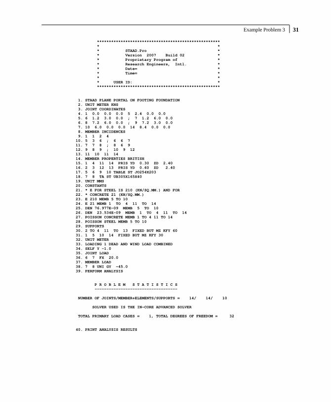
Example Problem 3 31
**************************************************** * * * STAAD.Pro * * Version 2007 Build 02 * * Proprietary Program of * * Research Engineers, Intl. * * Date= * * Time= * * * * USER ID: * **************************************************** 1. STAAD PLANE PORTAL ON FOOTING FOUNDATION 2. UNIT METER KNS 3. JOINT COORDINATES 4. 1 0.0 0.0 0.0 5 2.4 0.0 0.0 5. 6 1.2 3.0 0.0 ; 7 1.2 6.0 0.0 6. 8 7.2 6.0 0.0 ; 9 7.2 3.0 0.0 7. 10 6.0 0.0 0.0 14 8.4 0.0 0.0 8. MEMBER INCIDENCES 9. 1 1 2 4 10. 5 3 6 ; 6 6 7 11. 7 7 8 ; 8 6 9 12. 9 8 9 ; 10 9 12 13. 11 10 11 14 14. MEMBER PROPERTIES BRITISH 15. 1 4 11 14 PRIS YD 0.30 ZD 2.40 16. 2 3 12 13 PRIS YD 0.60 ZD 2.40 17. 5 6 9 10 TABLE ST JO254X203 18. 7 8 TA ST UB305X165X40 19. UNIT MMS 20. CONSTANTS 21. * E FOR STEEL IS 210 (KN/SQ.MM.) AND FOR 22. * CONCRETE 21 (KN/SQ.MM.) 23. E 210 MEMB 5 TO 10 24. E 21 MEMB 1 TO 4 11 TO 14 25. DEN 76.977E-09 MEMB 5 TO 10 26. DEN 23.534E-09 MEMB 1 TO 4 11 TO 14 27. POISSON CONCRETE MEMB 1 TO 4 11 TO 14 28. POISSON STEEL MEMB 5 TO 10 29. SUPPORTS 30. 2 TO 4 11 TO 13 FIXED BUT MZ KFY 60 31. 1 5 10 14 FIXED BUT MZ KFY 30 32. UNIT METER 33. LOADING 1 DEAD AND WIND LOAD COMBINED 34. SELF Y -1.0 35. JOINT LOAD 36. 6 7 FX 20.0 37. MEMBER LOAD 38. 7 8 UNI GY -45.0 39. PERFORM ANALYSIS P R O B L E M S T A T I S T I C S ----------------------------------- NUMBER OF JOINTS/MEMBER+ELEMENTS/SUPPORTS = 14/ 14/ 10 SOLVER USED IS THE IN-CORE ADVANCED SOLVER TOTAL PRIMARY LOAD CASES = 1, TOTAL DEGREES OF FREEDOM = 32 40. PRINT ANALYSIS RESULTS

Part I - Application Examples Example Problem 3 32
JOINT DISPLACEMENT (CM RADIANS) STRUCTURE TYPE = PLANE ------------------ JOINT LOAD X-TRANS Y-TRANS Z-TRANS X-ROTAN Y-ROTAN Z-ROTAN 1 1 0.0000 -0.1075 0.0000 0.0000 0.0000 -0.0003 2 1 0.0000 -0.1232 0.0000 0.0000 0.0000 -0.0002 3 1 0.0000 -0.1367 0.0000 0.0000 0.0000 -0.0002 4 1 0.0000 -0.1466 0.0000 0.0000 0.0000 -0.0002 5 1 0.0000 -0.1531 0.0000 0.0000 0.0000 -0.0001 6 1 0.5036 -0.1720 0.0000 0.0000 0.0000 -0.0032 7 1 1.0712 -0.1898 0.0000 0.0000 0.0000 -0.0045 8 1 1.0285 -0.2097 0.0000 0.0000 0.0000 0.0022 9 1 0.5240 -0.1902 0.0000 0.0000 0.0000 -0.0003 10 1 0.0000 -0.0897 0.0000 0.0000 0.0000 -0.0005 11 1 0.0000 -0.1210 0.0000 0.0000 0.0000 -0.0005 12 1 0.0000 -0.1504 0.0000 0.0000 0.0000 -0.0005 13 1 0.0000 -0.1759 0.0000 0.0000 0.0000 -0.0004 14 1 0.0000 -0.1969 0.0000 0.0000 0.0000 -0.0003 SUPPORT REACTIONS -UNIT KNS METE STRUCTURE TYPE = PLANE ----------------- JOINT LOAD FORCE-X FORCE-Y FORCE-Z MOM-X MOM-Y MOM Z 2 1 0.00 73.95 0.00 0.00 0.00 0.00 3 1 0.09 82.01 0.00 0.00 0.00 0.00 4 1 0.00 87.96 0.00 0.00 0.00 0.00 11 1 0.00 72.58 0.00 0.00 0.00 0.00 12 1 -40.09 90.25 0.00 0.00 0.00 0.00 13 1 0.00 105.55 0.00 0.00 0.00 0.00 1 1 0.00 32.25 0.00 0.00 0.00 0.00 5 1 0.00 45.92 0.00 0.00 0.00 0.00 10 1 0.00 26.90 0.00 0.00 0.00 0.00 14 1 0.00 59.06 0.00 0.00 0.00 0.00 MEMBER END FORCES STRUCTURE TYPE = PLANE ----------------- ALL UNITS ARE -- KNS METE (LOCAL ) MEMBER LOAD JT AXIAL SHEAR-Y SHEAR-Z TORSION MOM-Y MOM-Z 1 1 1 0.00 32.25 0.00 0.00 0.00 0.00 2 0.00 -22.08 0.00 0.00 0.00 16.30 2 1 2 0.00 96.03 0.00 0.00 0.00 -16.30 3 0.00 -75.69 0.00 0.00 0.00 67.82 3 1 3 0.00 -103.38 0.00 0.00 0.00 -92.63 4 0.00 123.71 0.00 0.00 0.00 24.50 4 1 4 0.00 -35.75 0.00 0.00 0.00 -24.50 5 0.00 45.92 0.00 0.00 0.00 0.00 5 1 3 261.08 -0.09 0.00 0.00 0.00 24.81 6 -258.66 0.09 0.00 0.00 0.00 -25.09 6 1 6 132.10 -56.74 0.00 0.00 0.00 -73.59 7 -129.67 56.74 0.00 0.00 0.00 -96.63 7 1 7 76.74 129.67 0.00 0.00 0.00 96.63 8 -76.74 142.70 0.00 0.00 0.00 -135.72 8 1 6 -36.65 126.56 0.00 0.00 0.00 98.68 9 36.65 145.80 0.00 0.00 0.00 -156.40 9 1 8 142.70 76.74 0.00 0.00 0.00 135.72 9 -145.12 -76.74 0.00 0.00 0.00 94.50 10 1 9 290.93 40.09 0.00 0.00 0.00 61.90 12 -293.35 -40.09 0.00 0.00 0.00 58.38

Example Problem 3 33 MEMBER END FORCES STRUCTURE TYPE = PLANE ----------------- ALL UNITS ARE -- KNS METE (LOCAL ) MEMBER LOAD JT AXIAL SHEAR-Y SHEAR-Z TORSION MOM-Y MOM-Z 11 1 10 0.00 26.90 0.00 0.00 0.00 0.00 11 0.00 -16.73 0.00 0.00 0.00 13.09 12 1 11 0.00 89.32 0.00 0.00 0.00 -13.09 12 0.00 -68.99 0.00 0.00 0.00 60.58 13 1 12 0.00 -134.12 0.00 0.00 0.00 -118.96 13 0.00 154.45 0.00 0.00 0.00 32.39 14 1 13 0.00 -48.90 0.00 0.00 0.00 -32.39 14 0.00 59.06 0.00 0.00 0.00 0.00 ************** END OF LATEST ANALYSIS RESULT ************** 41. FINISH *********** END OF THE STAAD.Pro RUN *********** **** DATE= TIME= **** ************************************************************ * For questions on STAAD.Pro, please contact * * Research Engineers Offices at the following locations * * * * Telephone Email * * USA: +1 (714)974-2500 [email protected] * * CANADA +1 (905)632-4771 [email protected] * * UK +44(1454)207-000 [email protected] * * FRANCE +33(0)1 64551084 [email protected] * * GERMANY +49/931/40468-71 [email protected] * * NORWAY +47 67 57 21 30 [email protected] * * SINGAPORE +65 6225-6158 [email protected] * * INDIA +91(033)4006-2021 [email protected] * * JAPAN +81(03)5952-6500 [email protected] * * CHINA +86(411)363-1983 [email protected] * * THAILAND +66(0)2645-1018/19 [email protected] * * * * North America [email protected] * * Europe [email protected] * * Asia [email protected] * ************************************************************

Part I - Application Examples Example Problem 3 34
NOTES

Example Problem 4 35
Example Problem No. 4
This example is a typical case of a load-dependent structure where the structural condition changes for different load cases. In this example, different bracing members are made inactive for different load cases. This is done to prevent these members from carrying any compressive forces.

Part I - Application Examples Example Problem 4 36
Actual input is shown in bold lettering followed by explanation. STAAD PLANE * A PLANE FRAME STRUCTURE WITH TENSION BRACING
Every input has to start with the word STAAD. The word PLANE signifies that the structure is a plane frame structure and the geometry is defined through X and Y axes.
UNIT METER KNS
Specifies the unit to be used. SET NL 3
This structure has to be analysed for 3 primary load cases. Consequently, the modeling of our problem requires us to define 3 sets of data, with each set containing a load case and an associated analysis command. Also, the members which get switched off in the analysis for any load case have to be restored for the analysis for the subsequent load case. To accommodate these requirements, it is necessary to have 2 commands, one called “SET NL” and the other called “CHANGE”. The SET NL command is used above to indicate the total number of primary load cases that the file contains. The CHANGE command will come in later (after the PERFORM ANALYSIS command).
JOINT COORDINATES 1 0 0 0 3 12. 0. 0. 4 0 4.5 0 6 12. 4.5 0. 7 6. 9. 0. ; 8 12. 9. 0.
Joint number followed by X, Y and Z coordinates are provided above. Since this is a plane structure, the Z coordinates are given as all zeros. Semicolon signs (;) are used as line separators, to facilitate specification of multiple sets of data on one line.
MEMBER INCIDENCE 1 1 4 2 ; 3 5 7 ; 4 3 6 ; 5 6 8 ; 6 4 5 7 8 7 8 ; 9 1 5 ; 10 2 4 ; 11 3 5 ; 12 2 6 13 6 7 ; 14 5 8

Example Problem 4 37
Defines the members by the joints they are connected to. MEMBER TRUSS 9 TO 14
The above command defines that members 9 through 14 are of type truss. This means these members can only carry axial tension/compression and no moments.
MEMBER PROP BRITISH 1 TO 5 TABLE ST UB305X165X40 6 7 8 TA ST UB457X152X52 9 TO 14 TA LD UA150X150X10
Properties for all members are assigned from the British steel table. The word ST stands for standard single section. The word LD stands for long leg back-to-back double angle. Since the spacing between the two angles of the double angle is not provided, it is assumed to be 0.0.
UNIT MMS CONSTANTS E 210. ALL POISSON STEEL ALL
The CONSTANT command initiates input for material constants like E (modulus of elasticity), Poisson’s ratio, etc. Length unit is changed from METER to MMS.
SUPPORT 1 2 3 PINNED
PINNED supports are specified at Joints 1, 2 and 3. The word PINNED signifies that no moments will be carried by these supports.
INACTIVE MEMBERS 9 TO 14
The above command makes the listed members inactive. The stiffness contribution of these members will not be considered in the analysis till they are made active again.
Part I - Application Examples Example Problem 4 38
UNIT METER LOADING 1 DEAD AND LIVE LOAD
Load case 1 is initiated followed by a title. The length UNIT is changed from MMS to METER for input values which follow.
MEMBER LOAD 6 8 UNI GY -4.5 7 UNI GY -6.75
Load 1 contains member loads. GY indicates that the load acts in the global Y direction. The word UNI stands for uniformly distributed load. The load is applied on members 6, 7 and 8.
PERFORM ANALYSIS
This command instructs the program to proceed with the analysis. It is worth noting that members 9 TO 14 will not be used in this analysis since they were declared inactive earlier. In other words, for dead and live load, the bracings are not used to carry any load.
CHANGES
The members inactivated earlier are restored using the CHANGE command.
INACTIVE MEMBERS 10 11 13
A new set of members are made inactive. The stiffness contribution from these members will not be used in the analysis till they are made active again. They have been inactivated to prevent them from being subject to compressive forces for the next load case.
LOADING 2 WIND FROM LEFT
Load case 2 is initiated followed by a title. JOINT LOAD 4 FX 135 ; 7 FX 65

Example Problem 4 39
Load 2 contains joint loads. FX indicates that the load is a force in the global X direction. Nodes 4 and 7 are subjected to the loads.
PERFORM ANALYSIS
This command instructs the program to proceed with the analysis. The analysis will be performed for load case 2 only.
CHANGE
The above CHANGE command is an instruction to re-activate all inactive members.
INACTIVE MEMBERS 9 12 14
Members 9, 12 and 14 are made inactive. The stiffness contribution of these members will not be used in the analysis till they are made active again. They have been inactivated to prevent them from being subject to compressive forces for the next load case.
LOADING 3 WIND FROM RIGHT
Load case 3 is initiated followed by a title. JOINT LOAD 6 FX -135 ; 8 FX -65
Load 3 contains joint loads at nodes 6 and 8. FX indicates that the load is a force in the global X direction. The negative numbers (-135 and -65) indicate that the load is acting along the negative global X direction.
LOAD COMBINATION 4 1 0.75 2 0.75 LOAD COMBINATION 5 1 0.75 3 0.75
Load combination case 4 involves the algebraic summation of the results of load cases 1 and 2 after multiplying each by a factor of 0.75. For load combinations, the program simply gathers the

Part I - Application Examples Example Problem 4 40
results of the component primary cases, factors them appropriately, and combines them algebraically. Thus, an analysis in the real sense of the term (multiplying the inverted stiffness matrix by the load vector) is not carried out for load combination cases. Load combination case 5 combines the results of load cases 1 and 3.
PERFORM ANALYSIS
This command instructs the program to proceed with the analysis. Only primary load case 3 will be considered for this analysis. (As explained earlier, a combination case is not truly analysed for, but handled using other means.)
CHANGE
The above CHANGE command will re-activate all inactive members.
LOAD LIST ALL
At the end of any analysis, only those load cases for which the analysis was done most recently, are recognized as the "active" load cases. The LOAD LIST ALL command enables all the load cases in the structure to be made active for further processing.
PRINT MEMBER FORCES
The above PRINT command is an instruction to produce a report, in the output file, of the member end forces.
LOAD LIST 1 4 5
A LOAD LIST command is a means of instructing the program to use only the listed load cases for further processing.
PARAMETER CODE BRITISH BEAM 1 ALL UNL 1.8 ALL KY 0.5 ALL
Example Problem 4 41
The PARAMETER command is used to specify the steel design parameters (information on these parameters can be obtained from the manual where the implementation of the code is explained). The BEAM parameter is specified to perform design at every 1/12th point along the member length. UNL represents the unsupported length to be used for calculation of allowable bending stress. KY 0.5 ALL sets the effective length factor for column buckling about the local Y-axis to be 0.5 for ALL members.
CHECK CODE ALL
The above command instructs the program to perform a check to determine how the user defined member sizes along with the latest analysis results meet the code requirements.
FINISH
This command terminates the STAAD run.
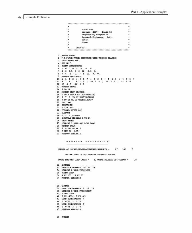
Part I - Application Examples Example Problem 4 42
**************************************************** * * * STAAD.Pro * * Version 2007 Build 02 * * Proprietary Program of * * Research Engineers, Intl. * * Date= * * Time= * * * * USER ID: * **************************************************** 1. STAAD PLANE 2. * A PLANE FRAME STRUCTURE WITH TENSION BRACING 3. UNIT METER KNS 4. SET NL 3 5. JOINT COORDINATES 6. 1 0 0 0 3 12. 0. 0. 7. 4 0 4.5 0 6 12. 4.5 0. 8. 7 6. 9. 0. ; 8 12. 9. 0. 9. MEMBER INCIDENCE 10. 1 1 4 2 ; 3 5 7 ; 4 3 6 ; 5 6 8 ; 6 4 5 7 11. 8 7 8 ; 9 1 5 ; 10 2 4 ; 11 3 5 ; 12 2 6 12. 13 6 7 ;14 5 8 13. MEMBER TRUSS 14. 9 TO 14 15. MEMBER PROP BRITISH 16. 1 TO 5 TABLE ST UB305X165X40 17. 6 7 8 TA ST UB457X152X52 18. 9 TO 14 TA LD UA150X150X10 19. UNIT MMS 20. CONSTANTS 21. E 210. ALL 22. POISSON STEEL ALL 23. SUPPORT 24. 1 2 3 PINNED 25. INACTIVE MEMBERS 9 TO 14 26. UNIT METER 27. LOADING 1 DEAD AND LIVE LOAD 28. MEMBER LOAD 29. 6 8 UNI GY -4.5 30. 7 UNI GY -6.75 31. PERFORM ANALYSIS P R O B L E M S T A T I S T I C S ----------------------------------- NUMBER OF JOINTS/MEMBER+ELEMENTS/SUPPORTS = 8/ 14/ 3 SOLVER USED IS THE IN-CORE ADVANCED SOLVER TOTAL PRIMARY LOAD CASES = 1, TOTAL DEGREES OF FREEDOM = 18 32. CHANGES 33. INACTIVE MEMBERS 10 11 13 34. LOADING 2 WIND FROM LEFT 35. JOINT LOAD 36. 4 FX 135 ; 7 FX 65 37. PERFORM ANALYSIS 38. CHANGE 39. INACTIVE MEMBERS 9 12 14 40. LOADING 3 WIND FROM RIGHT 41. JOINT LOAD 42. 6 FX -135 ; 8 FX -65 43. LOAD COMBINATION 4 44. 1 0.75 2 0.75 45. LOAD COMBINATION 5 46. 1 0.75 3 0.75 47. PERFORM ANALYSIS 48. CHANGE

Example Problem 4 43 49. LOAD LIST ALL 50. PRINT MEMBER FORCES MEMBER END FORCES STRUCTURE TYPE = PLANE ----------------- ALL UNITS ARE -- KNS METE (LOCAL ) MEMBER LOAD JT AXIAL SHEAR-Y SHEAR-Z TORSION MOM-Y MOM-Z 1 1 1 11.15 -0.90 0.00 0.00 0.00 0.00 4 -11.15 0.90 0.00 0.00 0.00 -4.06 2 1 -1.07 0.77 0.00 0.00 0.00 0.00 4 1.07 -0.77 0.00 0.00 0.00 3.47 3 1 68.13 -0.68 0.00 0.00 0.00 0.00 4 -68.13 0.68 0.00 0.00 0.00 -3.04 4 1 7.56 -0.10 0.00 0.00 0.00 0.00 4 -7.56 0.10 0.00 0.00 0.00 -0.44 5 1 59.46 -1.18 0.00 0.00 0.00 0.00 4 -59.46 1.18 0.00 0.00 0.00 -5.32 2 1 2 51.94 -0.07 0.00 0.00 0.00 0.00 5 -51.94 0.07 0.00 0.00 0.00 -0.32 2 2 46.14 0.53 0.00 0.00 0.00 0.00 5 -46.14 -0.53 0.00 0.00 0.00 2.40 3 2 129.19 -0.46 0.00 0.00 0.00 0.00 5 -129.19 0.46 0.00 0.00 0.00 -2.08 4 2 73.56 0.35 0.00 0.00 0.00 0.00 5 -73.56 -0.35 0.00 0.00 0.00 1.56 5 2 135.85 -0.40 0.00 0.00 0.00 0.00 5 -135.85 0.40 0.00 0.00 0.00 -1.80 3 1 5 13.68 -2.96 0.00 0.00 0.00 -5.29 7 -13.68 2.96 0.00 0.00 0.00 -8.01 2 5 -0.99 1.44 0.00 0.00 0.00 3.47 7 0.99 -1.44 0.00 0.00 0.00 3.02 3 5 47.37 -2.44 0.00 0.00 0.00 -6.16 7 -47.37 2.44 0.00 0.00 0.00 -4.81 4 5 9.52 -1.14 0.00 0.00 0.00 -1.37 7 -9.52 1.14 0.00 0.00 0.00 -3.75 5 5 45.79 -4.04 0.00 0.00 0.00 -8.59 7 -45.79 4.04 0.00 0.00 0.00 -9.62 4 1 3 31.40 0.97 0.00 0.00 0.00 0.00 6 -31.40 -0.97 0.00 0.00 0.00 4.38 2 3 103.80 0.21 0.00 0.00 0.00 0.00 6 -103.80 -0.21 0.00 0.00 0.00 0.93 3 3 -48.61 -0.59 0.00 0.00 0.00 0.00 6 48.61 0.59 0.00 0.00 0.00 -2.64 4 3 101.40 0.88 0.00 0.00 0.00 0.00 6 -101.40 -0.88 0.00 0.00 0.00 3.98 5 3 -12.91 0.29 0.00 0.00 0.00 0.00 6 12.91 -0.29 0.00 0.00 0.00 1.30 5 1 6 13.32 2.96 0.00 0.00 0.00 6.39 8 -13.32 -2.96 0.00 0.00 0.00 6.91 2 6 47.70 1.28 0.00 0.00 0.00 2.85 8 -47.70 -1.28 0.00 0.00 0.00 2.91 3 6 -1.29 -1.12 0.00 0.00 0.00 -2.14 8 1.29 1.12 0.00 0.00 0.00 -2.91 4 6 45.76 3.18 0.00 0.00 0.00 6.93 8 -45.76 -3.18 0.00 0.00 0.00 7.36 5 6 9.02 1.38 0.00 0.00 0.00 3.19 8 -9.02 -1.38 0.00 0.00 0.00 3.00 6 1 4 0.90 11.15 0.00 0.00 0.00 4.06 5 -0.90 15.85 0.00 0.00 0.00 -18.14 2 4 134.23 -1.07 0.00 0.00 0.00 -3.47 5 -134.23 1.07 0.00 0.00 0.00 -2.94 3 4 89.60 1.43 0.00 0.00 0.00 3.04 5 -89.60 -1.43 0.00 0.00 0.00 5.54 4 4 101.35 7.56 0.00 0.00 0.00 0.44 5 -101.35 12.69 0.00 0.00 0.00 -15.81 5 4 67.88 9.44 0.00 0.00 0.00 5.32 5 -67.88 10.81 0.00 0.00 0.00 -9.45
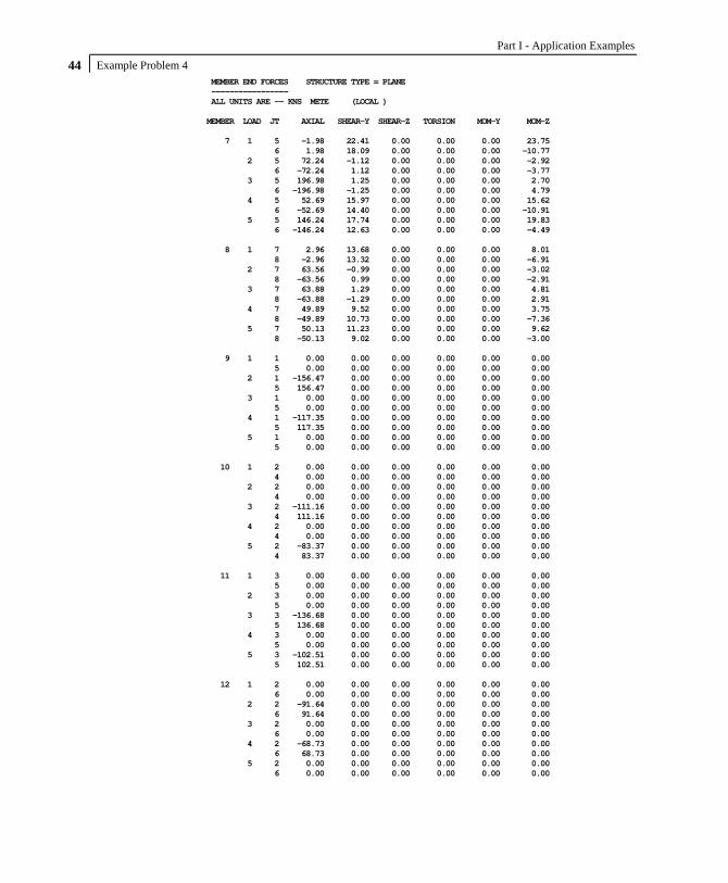
Part I - Application Examples Example Problem 4 44
MEMBER END FORCES STRUCTURE TYPE = PLANE ----------------- ALL UNITS ARE -- KNS METE (LOCAL ) MEMBER LOAD JT AXIAL SHEAR-Y SHEAR-Z TORSION MOM-Y MOM-Z 7 1 5 -1.98 22.41 0.00 0.00 0.00 23.75 6 1.98 18.09 0.00 0.00 0.00 -10.77 2 5 72.24 -1.12 0.00 0.00 0.00 -2.92 6 -72.24 1.12 0.00 0.00 0.00 -3.77 3 5 196.98 1.25 0.00 0.00 0.00 2.70 6 -196.98 -1.25 0.00 0.00 0.00 4.79 4 5 52.69 15.97 0.00 0.00 0.00 15.62 6 -52.69 14.40 0.00 0.00 0.00 -10.91 5 5 146.24 17.74 0.00 0.00 0.00 19.83 6 -146.24 12.63 0.00 0.00 0.00 -4.49 8 1 7 2.96 13.68 0.00 0.00 0.00 8.01 8 -2.96 13.32 0.00 0.00 0.00 -6.91 2 7 63.56 -0.99 0.00 0.00 0.00 -3.02 8 -63.56 0.99 0.00 0.00 0.00 -2.91 3 7 63.88 1.29 0.00 0.00 0.00 4.81 8 -63.88 -1.29 0.00 0.00 0.00 2.91 4 7 49.89 9.52 0.00 0.00 0.00 3.75 8 -49.89 10.73 0.00 0.00 0.00 -7.36 5 7 50.13 11.23 0.00 0.00 0.00 9.62 8 -50.13 9.02 0.00 0.00 0.00 -3.00 9 1 1 0.00 0.00 0.00 0.00 0.00 0.00 5 0.00 0.00 0.00 0.00 0.00 0.00 2 1 -156.47 0.00 0.00 0.00 0.00 0.00 5 156.47 0.00 0.00 0.00 0.00 0.00 3 1 0.00 0.00 0.00 0.00 0.00 0.00 5 0.00 0.00 0.00 0.00 0.00 0.00 4 1 -117.35 0.00 0.00 0.00 0.00 0.00 5 117.35 0.00 0.00 0.00 0.00 0.00 5 1 0.00 0.00 0.00 0.00 0.00 0.00 5 0.00 0.00 0.00 0.00 0.00 0.00 10 1 2 0.00 0.00 0.00 0.00 0.00 0.00 4 0.00 0.00 0.00 0.00 0.00 0.00 2 2 0.00 0.00 0.00 0.00 0.00 0.00 4 0.00 0.00 0.00 0.00 0.00 0.00 3 2 -111.16 0.00 0.00 0.00 0.00 0.00 4 111.16 0.00 0.00 0.00 0.00 0.00 4 2 0.00 0.00 0.00 0.00 0.00 0.00 4 0.00 0.00 0.00 0.00 0.00 0.00 5 2 -83.37 0.00 0.00 0.00 0.00 0.00 4 83.37 0.00 0.00 0.00 0.00 0.00 11 1 3 0.00 0.00 0.00 0.00 0.00 0.00 5 0.00 0.00 0.00 0.00 0.00 0.00 2 3 0.00 0.00 0.00 0.00 0.00 0.00 5 0.00 0.00 0.00 0.00 0.00 0.00 3 3 -136.68 0.00 0.00 0.00 0.00 0.00 5 136.68 0.00 0.00 0.00 0.00 0.00 4 3 0.00 0.00 0.00 0.00 0.00 0.00 5 0.00 0.00 0.00 0.00 0.00 0.00 5 3 -102.51 0.00 0.00 0.00 0.00 0.00 5 102.51 0.00 0.00 0.00 0.00 0.00 12 1 2 0.00 0.00 0.00 0.00 0.00 0.00 6 0.00 0.00 0.00 0.00 0.00 0.00 2 2 -91.64 0.00 0.00 0.00 0.00 0.00 6 91.64 0.00 0.00 0.00 0.00 0.00 3 2 0.00 0.00 0.00 0.00 0.00 0.00 6 0.00 0.00 0.00 0.00 0.00 0.00 4 2 -68.73 0.00 0.00 0.00 0.00 0.00 6 68.73 0.00 0.00 0.00 0.00 0.00 5 2 0.00 0.00 0.00 0.00 0.00 0.00 6 0.00 0.00 0.00 0.00 0.00 0.00

Example Problem 4 45 MEMBER END FORCES STRUCTURE TYPE = PLANE ----------------- ALL UNITS ARE -- KNS METE (LOCAL ) MEMBER LOAD JT AXIAL SHEAR-Y SHEAR-Z TORSION MOM-Y MOM-Z 13 1 6 0.00 0.00 0.00 0.00 0.00 0.00 7 0.00 0.00 0.00 0.00 0.00 0.00 2 6 0.00 0.00 0.00 0.00 0.00 0.00 7 0.00 0.00 0.00 0.00 0.00 0.00 3 6 -76.80 0.00 0.00 0.00 0.00 0.00 7 76.80 0.00 0.00 0.00 0.00 0.00 4 6 0.00 0.00 0.00 0.00 0.00 0.00 7 0.00 0.00 0.00 0.00 0.00 0.00 5 6 -57.60 0.00 0.00 0.00 0.00 0.00 7 57.60 0.00 0.00 0.00 0.00 0.00 14 1 5 0.00 0.00 0.00 0.00 0.00 0.00 8 0.00 0.00 0.00 0.00 0.00 0.00 2 5 -77.85 0.00 0.00 0.00 0.00 0.00 8 77.85 0.00 0.00 0.00 0.00 0.00 3 5 0.00 0.00 0.00 0.00 0.00 0.00 8 0.00 0.00 0.00 0.00 0.00 0.00 4 5 -58.39 0.00 0.00 0.00 0.00 0.00 8 58.39 0.00 0.00 0.00 0.00 0.00 5 5 0.00 0.00 0.00 0.00 0.00 0.00 8 0.00 0.00 0.00 0.00 0.00 0.00 ************** END OF LATEST ANALYSIS RESULT ************** 51. LOAD LIST 1 4 5 52. PARAMETER 53. CODE BRITISH 54. BEAM 1 ALL 55. UNL 1.8 ALL 56. KY 0.5 ALL 57. CHECK CODE ALL STAAD.Pro CODE CHECKING - (BSI ) *********************** PROGRAM CODE REVISION V2.10_5950-1_2000 ALL UNITS ARE - KNS METE (UNLESS OTHERWISE NOTED) MEMBER TABLE RESULT/ CRITICAL COND/ RATIO/ LOADING/ FX MY MZ LOCATION ======================================================================= 1 ST UB305X165X40 PASS BS-4.7 (C) 0.052 5 59.46 C 0.00 -5.32 4.50 2 ST UB305X165X40 PASS BS-4.7 (C) 0.118 5 135.85 C 0.00 -1.80 4.50 3 ST UB305X165X40 PASS BS-4.3.6 0.059 5 45.79 C 0.00 9.62 4.50 4 ST UB305X165X40 PASS BS-4.7 (C) 0.088 4 101.40 C 0.00 3.98 4.50 5 ST UB305X165X40 PASS BS-4.3.6 0.045 4 45.76 C 0.00 7.36 4.50 6 ST UB457X152X52 PASS BS-4.7 (C) 0.102 4 101.35 C 0.00 -15.81 6.00 7 ST UB457X152X52 PASS BS-4.7 (C) 0.147 5 146.24 C 0.00 19.83 0.00 8 ST UB457X152X52 PASS BS-4.7 (C) 0.050 5 50.13 C 0.00 9.62 0.00 9 LD UA150X150X10 PASS BS-4.6 (T) 0.072 4 117.35 T 0.00 0.00 0.00 10 LD UA150X150X10 PASS BS-4.6 (T) 0.051 5 83.37 T 0.00 0.00 0.00 11 LD UA150X150X10 PASS BS-4.6 (T) 0.063 5 102.51 T 0.00 0.00 0.00 12 LD UA150X150X10 PASS BS-4.6 (T) 0.042 4 68.73 T 0.00 0.00 0.00 13 LD UA150X150X10 PASS BS-4.6 (T) 0.036 5 57.60 T 0.00 0.00 0.00 14 LD UA150X150X10 PASS BS-4.6 (T) 0.036 4 58.39 T 0.00 0.00 0.00 ************** END OF TABULATED RESULT OF DESIGN **************

Part I - Application Examples Example Problem 4 46
58. FINISH *********** END OF THE STAAD.Pro RUN *********** **** DATE= TIME= **** ************************************************************ * For questions on STAAD.Pro, please contact * * Research Engineers Offices at the following locations * * * * Telephone Email * * USA: +1 (714)974-2500 [email protected] * * CANADA +1 (905)632-4771 [email protected] * * UK +44(1454)207-000 [email protected] * * FRANCE +33(0)1 64551084 [email protected] * * GERMANY +49/931/40468-71 [email protected] * * NORWAY +47 67 57 21 30 [email protected] * * SINGAPORE +65 6225-6158 [email protected] * * INDIA +91(033)4006-2021 [email protected] * * JAPAN +81(03)5952-6500 [email protected] * * CHINA +86(411)363-1983 [email protected] * * THAILAND +66(0)2645-1018/19 [email protected] * * * * North America [email protected] * * Europe [email protected] * * Asia [email protected] * ************************************************************

Example Problem 5 47
Example Problem No. 5
This example demonstrates the application of support displacement load (commonly known as sinking support) on a space frame structure.

Part I - Application Examples Example Problem 5 48
Actual input is shown in bold lettering followed by explanation. STAAD SPACE TEST FOR SUPPORT DISPLACEMENT
Every input has to start with the word STAAD. The word SPACE signifies that the structure is a space frame structure (3-D) and the geometry is defined through X, Y and Z coordinates.
UNITS METER KNS
Specifies the unit to be used. JOINT COORDINATES 1 0.0 0.0 0.0 ; 2 0.0 3.0 0.0 3 6.0 3.0 0.0 ; 4 6.0 0.0 0.0 5 6.0 3.0 6.0 ; 6 6.0 0.0. 6.0
Joint number followed by X, Y and Z coordinates are provided above. Semicolon signs (;) are used as line separators. That enables us to provide multiple sets of data on one line.
MEMBER INCIDENCE 1 1 2 3 4 3 5 ; 5 5 6
Defines the members by the joints they are connected to. UNIT MMS MEMB PROP 1 TO 5 PRIS AX 6450 IZ 1.249E+08 IY 1.249E+08 IX 4.162E+06
Member properties have been defined above using the PRISMATIC attribute. Values of AX (area), IZ (moment of inertia about major axis), IY (moment of inertia about minor axis) and IX (torsional constant) are provided in MMS unit.
CONSTANT E 210. ALL POISSON STEEL ALL
Material constants like E (modulus of elasticity) and Poisson’s ratio are specified following the command CONSTANT.

Example Problem 5 49
SUPPORT 1 4 6 FIXED
Joints 1, 4 and 6 are fixed supports. LOADING 1 SINKING SUPPORT
Load case 1 is initiated followed by a title. SUPPORT DISPLACEMENT LOAD 4 FY –15
Load 1 is a support displacement load which is also commonly known as a sinking support. FY signifies that the support settlement is in the global Y direction and the value of this settlement is 15mm downward.
PERFORM ANALYSIS
This command instructs the program to proceed with the analysis. PRINT ANALYSIS RESULTS
The above PRINT command instructs the program to print joint displacements, support reactions and member forces.
FINISH
This command terminates the STAAD run.
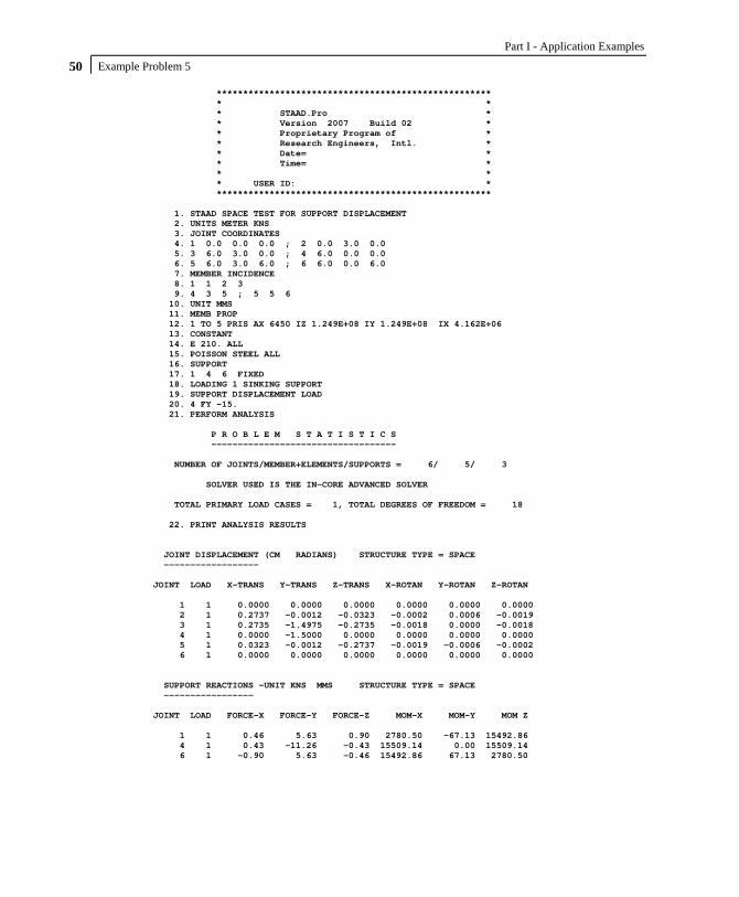
Part I - Application Examples Example Problem 5 50
**************************************************** * * * STAAD.Pro * * Version 2007 Build 02 * * Proprietary Program of * * Research Engineers, Intl. * * Date= * * Time= * * * * USER ID: * **************************************************** 1. STAAD SPACE TEST FOR SUPPORT DISPLACEMENT 2. UNITS METER KNS 3. JOINT COORDINATES 4. 1 0.0 0.0 0.0 ; 2 0.0 3.0 0.0 5. 3 6.0 3.0 0.0 ; 4 6.0 0.0 0.0 6. 5 6.0 3.0 6.0 ; 6 6.0 0.0 6.0 7. MEMBER INCIDENCE 8. 1 1 2 3 9. 4 3 5 ; 5 5 6 10. UNIT MMS 11. MEMB PROP 12. 1 TO 5 PRIS AX 6450 IZ 1.249E+08 IY 1.249E+08 IX 4.162E+06 13. CONSTANT 14. E 210. ALL 15. POISSON STEEL ALL 16. SUPPORT 17. 1 4 6 FIXED 18. LOADING 1 SINKING SUPPORT 19. SUPPORT DISPLACEMENT LOAD 20. 4 FY -15. 21. PERFORM ANALYSIS P R O B L E M S T A T I S T I C S ----------------------------------- NUMBER OF JOINTS/MEMBER+ELEMENTS/SUPPORTS = 6/ 5/ 3 SOLVER USED IS THE IN-CORE ADVANCED SOLVER TOTAL PRIMARY LOAD CASES = 1, TOTAL DEGREES OF FREEDOM = 18 22. PRINT ANALYSIS RESULTS JOINT DISPLACEMENT (CM RADIANS) STRUCTURE TYPE = SPACE ------------------ JOINT LOAD X-TRANS Y-TRANS Z-TRANS X-ROTAN Y-ROTAN Z-ROTAN 1 1 0.0000 0.0000 0.0000 0.0000 0.0000 0.0000 2 1 0.2737 -0.0012 -0.0323 -0.0002 0.0006 -0.0019 3 1 0.2735 -1.4975 -0.2735 -0.0018 0.0000 -0.0018 4 1 0.0000 -1.5000 0.0000 0.0000 0.0000 0.0000 5 1 0.0323 -0.0012 -0.2737 -0.0019 -0.0006 -0.0002 6 1 0.0000 0.0000 0.0000 0.0000 0.0000 0.0000 SUPPORT REACTIONS -UNIT KNS MMS STRUCTURE TYPE = SPACE ----------------- JOINT LOAD FORCE-X FORCE-Y FORCE-Z MOM-X MOM-Y MOM Z 1 1 0.46 5.63 0.90 2780.50 -67.13 15492.86 4 1 0.43 -11.26 -0.43 15509.14 0.00 15509.14 6 1 -0.90 5.63 -0.46 15492.86 67.13 2780.50

Example Problem 5 51 MEMBER END FORCES STRUCTURE TYPE = SPACE ----------------- ALL UNITS ARE -- KNS MMS (LOCAL ) MEMBER LOAD JT AXIAL SHEAR-Y SHEAR-Z TORSION MOM-Y MOM-Z 1 1 1 5.63 -0.46 0.90 -67.13 -2780.50 15492.86 2 -5.63 0.46 -0.90 67.13 94.34 -16878.24 2 1 2 0.46 5.63 0.90 94.34 -67.13 16878.24 3 -0.46 -5.63 -0.90 -94.34 -5305.17 16904.26 3 1 3 -11.26 -0.43 0.43 0.00 -16809.91 -16809.91 4 11.26 0.43 -0.43 0.00 15509.14 15509.14 4 1 3 0.46 -5.63 -0.90 -94.34 5305.17 -16904.26 5 -0.46 5.63 0.90 94.34 67.13 -16878.24 5 1 5 5.63 0.90 0.46 67.13 -16878.24 -94.34 6 -5.63 -0.90 -0.46 -67.13 15492.86 2780.50 ************** END OF LATEST ANALYSIS RESULT ************** 23. FINISH *********** END OF THE STAAD.Pro RUN *********** **** DATE= TIME= **** ************************************************************ * For questions on STAAD.Pro, please contact * * Research Engineers Offices at the following locations * * * * Telephone Email * * USA: +1 (714)974-2500 [email protected] * * CANADA +1 (905)632-4771 [email protected] * * UK +44(1454)207-000 [email protected] * * FRANCE +33(0)1 64551084 [email protected] * * GERMANY +49/931/40468-71 [email protected] * * NORWAY +47 67 57 21 30 [email protected] * * SINGAPORE +65 6225-6158 [email protected] * * INDIA +91(033)4006-2021 [email protected] * * JAPAN +81(03)5952-6500 [email protected] * * CHINA +86(411)363-1983 [email protected] * * THAILAND +66(0)2645-1018/19 [email protected] * * * * North America [email protected] * * Europe [email protected] * * Asia [email protected] * ************************************************************

Part I - Application Examples Example Problem 5 52
NOTES

Example Problem 6 53
Example Problem No. 6
This is an example of prestress loading in a plane frame structure. It covers two situations: 1) From the member on which it is applied, the prestressing effect is transmitted to the rest of the structure through the connecting members (known in the program as PRESTRESS load). 2) The prestressing effect is experienced by the member(s) alone and not transmitted to the rest of the structure (known in the program as POSTSTRESS load).

Part I - Application Examples Example Problem 6 54
Actual input is shown in bold lettering followed by explanation. STAAD PLANE FRAME WITH PRESTRESSING LOAD
Every input has to start with the word STAAD. The word PLANE signifies that the structure is a plane frame structure and the geometry is defined through X and Y axes.
UNIT METER KNS
Specifies the unit to be used. JOINT COORD 1 0. 0. ; 2 12. 0. ; 3 0. 6. ; 4 12. 6. 5 0. 10.5 ; 6 12. 10.5 ; 7 0. 15. ; 8 12. 15.
Joint number followed by X and Y coordinates are provided above. Since this is a plane structure, the Z coordinates need not be provided. Semicolon signs (;) are used as line separators, and that allows us to provide multiple sets of data on one line.
MEMBER INCIDENCE 1 1 3 ; 2 3 5 ; 3 5 7 ; 4 2 4 ; 5 4 6 6 6 8 ; 7 3 4 ; 8 5 6 ; 9 7 8
Defines the members by the joints they are connected to. SUPPORT 1 2 FIXED
The supports at joints 1 and 2 are defined to be fixed supports. MEMB PROP 1 TO 9 PRI AX 0.2044 IZ 8.631E-03
Member properties are provided using the PRI (prismatic) attribute. Values of area (AX) and moment of inertia about the major axis (IZ) are provided.
UNIT MMS CONSTANT E 21. ALL ; POISS CONC ALL

Example Problem 6 55
CONSTANT command initiates input for material constants like E (modulus of elasticity), Poisson’s ratio, etc. Length unit is changed from METER to MMS to facilitate the input.
LOADING 1 PRESTRESSING LOAD MEMBER PRESTRESS 7 8 FORCE 1350. ES 75. EM -300. EE 75.
Load case 1 is initiated followed by a title. Load 1 contains PRESTRESS load. Members 7 and 8 have a cable force of 1350 KNs. The location of the cable at the start (ES) and end (EE) is 75 MMs above the centre of gravity while at the middle (EM) it is 300 MMs below the c.g. The assumptions and facts associated with this type of loading are explained in section 1 of the Technical Reference Manual.
LOADING 2 POSTSTRESSING LOAD MEMBER POSTSTRESS 7 8 FORCE 1350. ES 75. EM -300. EE 75.
Load case 2 is initiated followed by a title. Load 2 is a POSTSTRESS load. Members 7 and 8 have a cable force of 1350 KNs. The location of the cable is the same as in load case 1. For a difference between PRESTRESS loading and POSTSTRESS loading, as well as additional information about both types of loads, please refer to section 1 of the Technical Reference Manual.
PERFORM ANALYSIS
This command instructs the program to perform the analysis. UNIT METER PRINT ANALYSIS RESULTS
The above command is an instruction to write joint displacements, support reactions and member forces in the output file.
FINISH
This command terminates the STAAD run.
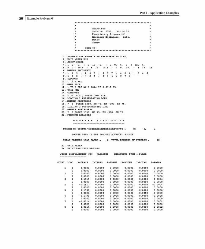
Part I - Application Examples Example Problem 6 56
**************************************************** * * * STAAD.Pro * * Version 2007 Build 02 * * Proprietary Program of * * Research Engineers, Intl. * * Date= * * Time= * * * * USER ID: * **************************************************** 1. STAAD PLANE FRAME WITH PRESTRESSING LOAD 2. UNIT METER KNS 3. JOINT COORD 4. 1 0. 0. ; 2 12. 0. ; 3 0. 6. ; 4 12. 6. 5. 5 0. 10.5 ; 6 12. 10.5 ; 7 0. 15. ; 8 12. 15. 6. MEMBER INCIDENCE 7. 1 1 3 ; 2 3 5 ; 3 5 7 ; 4 2 4 ; 5 4 6 8. 6 6 8 ; 7 3 4 ; 8 5 6 ; 9 7 8 9. SUPPORT 10. 1 2 FIXED 11. MEMB PROP 12. 1 TO 9 PRI AX 0.2044 IZ 8.631E-03 13. UNIT MMS 14. CONSTANT 15. E 21. ALL ; POISS CONC ALL 16. LOADING 1 PRESTRESSING LOAD 17. MEMBER PRESTRESS 18. 7 8 FORCE 1350. ES 75. EM -300. EE 75. 19. LOADING 2 POSTSTRESSING LOAD 20. MEMBER POSTSTRESS 21. 7 8 FORCE 1350. ES 75. EM -300. EE 75. 22. PERFORM ANALYSIS P R O B L E M S T A T I S T I C S ----------------------------------- NUMBER OF JOINTS/MEMBER+ELEMENTS/SUPPORTS = 8/ 9/ 2 SOLVER USED IS THE IN-CORE ADVANCED SOLVER TOTAL PRIMARY LOAD CASES = 2, TOTAL DEGREES OF FREEDOM = 18 23. UNIT METER 24. PRINT ANALYSIS RESULTS JOINT DISPLACEMENT (CM RADIANS) STRUCTURE TYPE = PLANE ------------------ JOINT LOAD X-TRANS Y-TRANS Z-TRANS X-ROTAN Y-ROTAN Z-ROTAN 1 1 0.0000 0.0000 0.0000 0.0000 0.0000 0.0000 2 0.0000 0.0000 0.0000 0.0000 0.0000 0.0000 2 1 0.0000 0.0000 0.0000 0.0000 0.0000 0.0000 2 0.0000 0.0000 0.0000 0.0000 0.0000 0.0000 3 1 0.1917 0.0000 0.0000 0.0000 0.0000 0.0004 2 0.0000 0.0000 0.0000 0.0000 0.0000 0.0000 4 1 -0.1917 0.0000 0.0000 0.0000 0.0000 -0.0004 2 0.0000 0.0000 0.0000 0.0000 0.0000 0.0000 5 1 0.1799 0.0000 0.0000 0.0000 0.0000 0.0008 2 0.0000 0.0000 0.0000 0.0000 0.0000 0.0000 6 1 -0.1799 0.0000 0.0000 0.0000 0.0000 -0.0008 2 0.0000 0.0000 0.0000 0.0000 0.0000 0.0000 7 1 -0.0014 0.0000 0.0000 0.0000 0.0000 0.0002 2 0.0000 0.0000 0.0000 0.0000 0.0000 0.0000 8 1 0.0014 0.0000 0.0000 0.0000 0.0000 -0.0002 2 0.0000 0.0000 0.0000 0.0000 0.0000 0.0000

Example Problem 6 57 SUPPORT REACTIONS -UNIT KNS METE STRUCTURE TYPE = PLANE ----------------- JOINT LOAD FORCE-X FORCE-Y FORCE-Z MOM-X MOM-Y MOM Z 1 1 -30.59 0.00 0.00 0.00 0.00 80.49 2 0.00 0.00 0.00 0.00 0.00 0.00 2 1 30.59 0.00 0.00 0.00 0.00 -80.49 2 0.00 0.00 0.00 0.00 0.00 0.00 MEMBER END FORCES STRUCTURE TYPE = PLANE ----------------- ALL UNITS ARE -- KNS METE (LOCAL ) MEMBER LOAD JT AXIAL SHEAR-Y SHEAR-Z TORSION MOM-Y MOM-Z 1 1 1 0.00 30.59 0.00 0.00 0.00 80.49 3 0.00 -30.59 0.00 0.00 0.00 103.07 2 1 0.00 0.00 0.00 0.00 0.00 0.00 3 0.00 0.00 0.00 0.00 0.00 0.00 2 1 3 0.00 62.59 0.00 0.00 0.00 121.89 5 0.00 -62.59 0.00 0.00 0.00 159.77 2 3 0.00 0.00 0.00 0.00 0.00 0.00 5 0.00 0.00 0.00 0.00 0.00 0.00 3 1 5 0.00 10.30 0.00 0.00 0.00 50.98 7 0.00 -10.30 0.00 0.00 0.00 -4.64 2 5 0.00 0.00 0.00 0.00 0.00 0.00 7 0.00 0.00 0.00 0.00 0.00 0.00 4 1 2 0.00 -30.59 0.00 0.00 0.00 -80.49 4 0.00 30.59 0.00 0.00 0.00 -103.07 2 2 0.00 0.00 0.00 0.00 0.00 0.00 4 0.00 0.00 0.00 0.00 0.00 0.00 5 1 4 0.00 -62.59 0.00 0.00 0.00 -121.89 6 0.00 62.59 0.00 0.00 0.00 -159.77 2 4 0.00 0.00 0.00 0.00 0.00 0.00 6 0.00 0.00 0.00 0.00 0.00 0.00 6 1 6 0.00 -10.30 0.00 0.00 0.00 -50.98 8 0.00 10.30 0.00 0.00 0.00 4.64 2 6 0.00 0.00 0.00 0.00 0.00 0.00 8 0.00 0.00 0.00 0.00 0.00 0.00 7 1 3 1371.41 -168.75 0.00 0.00 0.00 -326.21 4 -1371.41 -168.75 0.00 0.00 0.00 326.21 2 3 1339.41 -168.75 0.00 0.00 0.00 -101.25 4 -1339.41 -168.75 0.00 0.00 0.00 101.25 8 1 5 1287.12 -168.75 0.00 0.00 0.00 -312.00 6 -1287.12 -168.75 0.00 0.00 0.00 312.00 2 5 1339.41 -168.75 0.00 0.00 0.00 -101.25 6 -1339.41 -168.75 0.00 0.00 0.00 101.25 9 1 7 -10.30 0.00 0.00 0.00 0.00 4.64 8 10.30 0.00 0.00 0.00 0.00 -4.64 2 7 0.00 0.00 0.00 0.00 0.00 0.00 8 0.00 0.00 0.00 0.00 0.00 0.00 ************** END OF LATEST ANALYSIS RESULT **************

Part I - Application Examples Example Problem 6 58
25. FINISH *********** END OF THE STAAD.Pro RUN *********** **** DATE= TIME= **** ************************************************************ * For questions on STAAD.Pro, please contact * * Research Engineers Offices at the following locations * * * * Telephone Email * * USA: +1 (714)974-2500 [email protected] * * CANADA +1 (905)632-4771 [email protected] * * UK +44(1454)207-000 [email protected] * * FRANCE +33(0)1 64551084 [email protected] * * GERMANY +49/931/40468-71 [email protected] * * NORWAY +47 67 57 21 30 [email protected] * * SINGAPORE +65 6225-6158 [email protected] * * INDIA +91(033)4006-2021 [email protected] * * JAPAN +81(03)5952-6500 [email protected] * * CHINA +86(411)363-1983 [email protected] * * THAILAND +66(0)2645-1018/19 [email protected] * * * * North America [email protected] * * Europe [email protected] * * Asia [email protected] * ************************************************************

Example Problem 7 59
Example Problem No. 7
This example illustrates modelling of structures with OFFSET connections. OFFSET connections arise when the centre lines of the connected members do not intersect at the connection point. The connection eccentricity behaves as a rigid link and is modeled through specification of MEMBER OFFSETS.

Part I - Application Examples Example Problem 7 60
Actual input is shown in bold lettering followed by explanation. STAAD PLANE TEST FOR MEMBER OFFSETS
Every input has to start with the word STAAD. The word PLANE signifies that the structure is a plane frame structure and the geometry is defined through X and Y axes.
UNIT METER KNS
Specifies the unit to be used. JOINT COORD 1 0. 0. ; 2 6. 0. ; 3 0. 4.5 4 6. 4.5 ; 5 0. 9. ; 6 6. 9.
Joint number followed by X and Y coordinates are provided above. Since this is a plane structure, the Z coordinates need not be provided. Semicolon signs (;) are used as line separators. This allows us to provide multiple sets of data in one line.
SUPPORT 1 2 PINNED
Pinned supports are specified at joints 1 and 2. The word PINNED signifies that no moments will be carried by these supports.
MEMB INCI 1 1 3 2 ; 3 3 5 4 5 3 4 ; 6 5 6 ; 7 1 4
Defines the members by the joints they are connected to. MEMB PROP BRITISH 1 TO 4 TABLE ST UC356X368X129 5 6 TA ST UB305X165X40 7 TA LD UA200X150X12
All member properties are from British steel table. The word ST stands for standard single section. LD stands for long leg back-to-back double angle.

Example Problem 7 61
UNIT MMS MEMB OFFSET 5 6 START 178. 0.0 0.0 5 6 END -178. 0.0 0.0 7 END -178.0 -152.0 0.0
The above specification states that an OFFSET is located at the START/END joint of the members. The X, Y and Z global coordinates of the offset distance from the corresponding incident joint are also provided. These attributes are applied to members 5, 6 and 7.
CONSTANT E 210. ALL POISSON STEEL ALL
Material constants like E (modulus of elasticity) and Poisson’s ratio are provided following the keyword CONSTANT.
LOADING 1 WIND LOAD
Load case 1 is initiated followed by a title. JOINT LOAD 3 FX 225.0 ; 5 FX 112.5
Load 1 contains joint loads at nodes 3 and 5. FX indicates that the load is a force in the global X direction.
PERFORM ANALYSIS
The above command is an instruction to perform the analysis. UNIT METER PRINT FORCES PRINT REACTIONS
The above PRINT commands are instructions for writing the member forces and support reactions to the output file.

Part I - Application Examples Example Problem 7 62
FINISH
This command terminates a STAAD run.

Example Problem 7 63
**************************************************** * * * STAAD.Pro * * Version 2007 Build 02 * * Proprietary Program of * * Research Engineers, Intl. * * Date= * * Time= * * * * USER ID: * **************************************************** 1. STAAD PLANE TEST FOR MEMBER OFFSETS 2. UNIT METER KNS 3. JOINT COORD 4. 1 0. 0. ; 2 6. 0. ; 3 0. 4.5 5. 4 6. 4.5 ; 5 0. 9. ; 6 6. 9. 6. SUPPORT 7. 1 2 PINNED 8. MEMB INCI 9. 1 1 3 2 ; 3 3 5 4 10. 5 3 4 ; 6 5 6 ; 7 1 4 11. MEMB PROP BRITISH 12. 1 TO 4 TABLE ST UC356X368X129 13. 5 6 TA ST UB305X165X40 14. 7 TA LD UA200X150X12 15. UNIT MMS 16. MEMB OFFSET 17. 5 6 START 178. 0.0 0.0 18. 5 6 END -178. 0.0 0.0 19. 7 END -178.0 -152.0 0.0 20. CONSTANT 21. E 210. ALL 22. POISSON STEEL ALL 23. LOADING 1 WIND LOAD 24. JOINT LOAD 25. 3 FX 225.0 ; 5 FX 112.5 26. PERFORM ANALYSIS P R O B L E M S T A T I S T I C S ----------------------------------- NUMBER OF JOINTS/MEMBER+ELEMENTS/SUPPORTS = 6/ 7/ 2 SOLVER USED IS THE IN-CORE ADVANCED SOLVER TOTAL PRIMARY LOAD CASES = 1, TOTAL DEGREES OF FREEDOM = 14 27. UNIT METER 28. PRINT FORCES MEMBER END FORCES STRUCTURE TYPE = PLANE ----------------- ALL UNITS ARE -- KNS METE (LOCAL ) MEMBER LOAD JT AXIAL SHEAR-Y SHEAR-Z TORSION MOM-Y MOM-Z 1 1 1 -49.12 -20.25 0.00 0.00 0.00 4.59 3 49.12 20.25 0.00 0.00 0.00 -95.70 2 1 2 337.50 -25.13 0.00 0.00 0.00 0.00 4 -337.50 25.13 0.00 0.00 0.00 -113.07 3 1 3 -30.76 53.78 0.00 0.00 0.00 151.00 5 30.76 -53.78 0.00 0.00 0.00 91.03 4 1 4 30.76 58.72 0.00 0.00 0.00 170.71 6 -30.76 -58.72 0.00 0.00 0.00 93.52

Part I - Application Examples Example Problem 7 64
MEMBER END FORCES STRUCTURE TYPE = PLANE ----------------- ALL UNITS ARE -- KNS METE (LOCAL ) MEMBER LOAD JT AXIAL SHEAR-Y SHEAR-Z TORSION MOM-Y MOM-Z 5 1 3 299.03 -18.37 0.00 0.00 0.00 -52.03 4 -299.03 18.37 0.00 0.00 0.00 -51.62 6 1 5 58.72 -30.76 0.00 0.00 0.00 -85.55 6 -58.72 30.76 0.00 0.00 0.00 -88.04 7 1 1 -479.32 -1.95 0.00 0.00 0.00 -4.59 4 479.32 1.95 0.00 0.00 0.00 -9.61 ************** END OF LATEST ANALYSIS RESULT ************** 29. PRINT REACTIONS SUPPORT REACTIONS -UNIT KNS METE STRUCTURE TYPE = PLANE ----------------- JOINT LOAD FORCE-X FORCE-Y FORCE-Z MOM-X MOM-Y MOM Z 1 1 -362.63 -337.50 0.00 0.00 0.00 0.00 2 1 25.13 337.50 0.00 0.00 0.00 0.00 ************** END OF LATEST ANALYSIS RESULT ************** 30. FINISH *********** END OF THE STAAD.Pro RUN *********** **** DATE= TIME= **** ************************************************************ * For questions on STAAD.Pro, please contact * * Research Engineers Offices at the following locations * * * * Telephone Email * * USA: +1 (714)974-2500 [email protected] * * CANADA +1 (905)632-4771 [email protected] * * UK +44(1454)207-000 [email protected] * * FRANCE +33(0)1 64551084 [email protected] * * GERMANY +49/931/40468-71 [email protected] * * NORWAY +47 67 57 21 30 [email protected] * * SINGAPORE +65 6225-6158 [email protected] * * INDIA +91(033)4006-2021 [email protected] * * JAPAN +81(03)5952-6500 [email protected] * * CHINA +86(411)363-1983 [email protected] * * THAILAND +66(0)2645-1018/19 [email protected] * * * * North America [email protected] * * Europe [email protected] * * Asia [email protected] * ************************************************************

Example Problem 8 65
Example Problem No. 8
In this example, concrete design is performed on some members of a space frame structure. Design calculations consist of computation of reinforcement for beams and columns. Secondary moments on the columns are obtained through the means of a P-Delta analysis.
The above example represents a space frame, and the members are made of concrete. The input in the next page will show the dimensions of the members. Two load cases, namely one for dead plus live load and another with dead, live and wind load, are considered in the design.

Part I - Application Examples Example Problem 8 66
Actual input is shown in bold lettering followed by explanation. STAAD SPACE FRAME WITH CONCRETE DESIGN
Every input has to start with the word STAAD. The word SPACE signifies that the structure is a space frame structure (3-D) and the geometry is defined through X, Y and Z coordinates.
UNIT METER KNS
Specifies the unit to be used. JOINT COORDINATE 1 0 0 0 ; 2 5.4 0 0 ; 3 11.4 0. 0 4 0 0 7.2 ; 5 5.4 0 7.2 ; 6 11.4 0 7.2 7 0 3.6 0 ; 8 5.4 3.6 0 ; 9 11.4 3.6 0 10 0 3.6 7.2 ; 11 5.4 3.6 7.2 ; 12 11.4 3.6 7.2 13 5.4 7.2 0 ; 14 11.4 7.2 0 ; 15 5.4 7.2 7.2 16 11.4 7.2 7.2
Joint number followed by X, Y and Z coordinates are provided above. Semicolon signs (;) are used as line separators to facilitate input of multiple sets of data on one line.
MEMBER INCIDENCE 1 1 7 ; 2 4 10 ; 3 2 8 ; 4 8 13 5 5 11 ; 6 11 15 ; 7 3 9 ; 8 9 14 9 6 12 ; 10 12 16 ; 11 7 8 12 13 10 11 14 ; 15 13 14 ; 16 15 16 17 7 10 ; 18 8 11 ; 19 9 12 20 13 15 ; 21 14 16
Defines the members by the joints they are connected to.
UNIT MMS MEMB PROP 1 2 PRISMATIC YD 300.0 IZ 2.119E08 IY 2.119E08 - IX 4.237E08 3 TO 10 PR YD 300.0 ZD 300.0 IZ 3.596E08 IY 3.596E08 – IX 5.324E08 11 TO 21 PR YD 535.0 ZD 380 IZ 2.409E09 IY 1.229E09 – IX 2.704E09

Example Problem 8 67
All member properties are provided using the PRISMATIC option. YD and ZD stand for depth and width. If ZD is not provided, a circular shape with diameter = YD is assumed for that cross section. All properties required for the analysis, such as, Area, Moments of Inertia, etc. are calculated automatically from these dimensions unless these are explicitly defined. For this particular example, moments of inertia (IZ, IY) and torsional constant (IX) are provided, so these will not be re-calculated. The IX, IY, and IZ values provided in this example are only half the values of a full section to account for the fact that the full moments of inertia will not be effective due to cracking of concrete.
CONSTANT E 21.0 ALL POISSON CONC ALL UNIT METER CONSTANT DEN 23.56 ALL
The CONSTANT command initiates input for material constants like E (modulus of elasticity), Poisson’s ratio, Density, etc. Length unit is changed from MM to METER to facilitate input for DENsity. The built-in value for Poisson’s ratio for concrete will be used in the analysis.
SUPPORT 1 TO 6 FIXED
Joints 1 to 6 are fixed supports. LOAD 1 (1.4DL + 1.7LL)
Load case 1 is initiated followed by a title. SELF Y -1.4
The selfweight of the structure is applied in the global Y direction with a -1.4 factor. Since global Y is vertically upward, the negative factor indicates that this load will act downwards.

Part I - Application Examples Example Problem 8 68
MEMB LOAD 11 TO 16 UNI Y -42.0 11 TO 16 UNI Y -76.5
Load 1 contains member loads also. Y indicates that the load is in the local Y direction. The word UNI stands for uniformly distributed load.
LOAD 2 .75 (1.4DL + 1.7LL + 1.7WL)
Load case 2 is initiated followed by a title.
REPEAT LOAD 1 0.75
The above command will gather the load data values from load case 1, multiply them with a factor of 0.75 and utilize the resulting values in load 2.
JOINT LOAD 15 16 FZ 40.0 11 FZ 90.0 12 FZ 70.0 10 FZ 40.0
Load 2 contains some additional joint loads also. FZ indicates that the load is a force in the global Z direction.
PDELTA ANALYSIS
This command instructs the program to proceed with the analysis. The analysis type is P-DELTA indicating that second-order effects are to be calculated.
PRINT FORCES LIST 2 5 9 14 16
Member end forces are printed using the above PRINT commands. The LIST option restricts the print output to the members listed.

Example Problem 8 69
START CONCRETE DESIGN
The above command initiates a concrete design. CODE BRITISH TRACK 1.0 MEMB 14 TRACK 2.0 MEMB 16 MAXMAIN 40 ALL
The values for the concrete design parameters are defined in the above commands. Design is performed per the BS 8110 Code. The TRACK value dictates the extent of design related information provided in the output. MAXMAIN indicates that the maximum size of main reinforcement is the 40 mm bar. These parameters are described in the manual where British concrete design related information is available.
DESIGN BEAM 14 16
The above command instructs the program to design beams 14 and 16 for flexure, shear and torsion.
DESIGN COLUMN 2 5
The above command instructs the program to design columns 2 and 5 for axial load and biaxial bending.
END CONCRETE DESIGN
This will end the concrete design. FINISH
This command terminates the STAAD run.

Part I - Application Examples Example Problem 8 70
**************************************************** * * * STAAD.Pro * * Version 2007 Build 02 * * Proprietary Program of * * Research Engineers, Intl. * * Date= * * Time= * * * * USER ID: * **************************************************** 1. STAAD SPACE FRAME WITH CONCRETE DESIGN 2. UNIT METER KNS 3. JOINT COORDINATE 4. 1 0 0 0 ; 2 5.4 0 0 ; 3 11.4 0. 0 5. 4 0 0 7.2 ; 5 5.4 0 7.2 ; 6 11.4 0 7.2 6. 7 0 3.6 0 ; 8 5.4 3.6 0 ; 9 11.4 3.6 0 7. 10 0 3.6 7.2 ; 11 5.4 3.6 7.2 ; 12 11.4 3.6 7.2 8. 13 5.4 7.2 0 ; 14 11.4 7.2 0 ; 15 5.4 7.2 7.2 9. 16 11.4 7.2 7.2 10. MEMBER INCIDENCE 11. 1 1 7 ; 2 4 10 ; 3 2 8 ; 4 8 13 12. 5 5 11 ; 6 11 15 ; 7 3 9 ; 8 9 14 13. 9 6 12 ; 10 12 16 ; 11 7 8 12 14. 13 10 11 14 ; 15 13 14 ; 16 15 16 15. 17 7 10 ; 18 8 11 ; 19 9 12 16. 20 13 15 ; 21 14 16 17. UNIT MMS 18. MEMB PROP 19. 1 2 PRISMATIC YD 300.0 IZ 2.119E08 IY 2.119E08 - 20. IX 4.237E08 21. 3 TO 10 PR YD 300.0 ZD 300.0 IZ 3.596E08 IY 3.596E08 - 22. IX 5.324E08 23. 11 TO 21 PR YD 535.0 ZD 380 IZ 2.409E09 IY 1.229E09 - 24. IX 2.704E09 25. CONSTANT 26. E 21.0 ALL 27. POISSON CONC ALL 28. UNIT METER 29. CONSTANT 30. DEN 23.56 ALL 31. SUPPORT 32. 1 TO 6 FIXED 33. LOAD 1 (1.4DL + 1.7LL) 34. SELF Y -1.4 35. MEMB LOAD 36. 11 TO 16 UNI Y -42.0 37. 11 TO 16 UNI Y -76.5 38. LOAD 2 .75 (1.4DL + 1.7LL + 1.7WL) 39. REPEAT LOAD 40. 1 0.75 41. JOINT LOAD 42. 15 16 FZ 40.0 43. 11 FZ 90.0 44. 12 FZ 70.0 45. 10 FZ 40.0 46. PDELTA ANALYSIS P R O B L E M S T A T I S T I C S ----------------------------------- NUMBER OF JOINTS/MEMBER+ELEMENTS/SUPPORTS = 16/ 21/ 6 SOLVER USED IS THE IN-CORE ADVANCED SOLVER TOTAL PRIMARY LOAD CASES = 2, TOTAL DEGREES OF FREEDOM = 60 47. PRINT FORCES LIST 2 5 9 14 16

Example Problem 8 71 MEMBER END FORCES STRUCTURE TYPE = SPACE ----------------- ALL UNITS ARE -- KNS METE (LOCAL ) MEMBER LOAD JT AXIAL SHEAR-Y SHEAR-Z TORSION MOM-Y MOM-Z 2 1 4 302.06 -18.38 -2.86 0.00 3.42 -23.51 10 -293.67 18.38 2.86 0.00 6.88 -42.65 2 4 243.86 -15.23 -31.79 1.32 57.70 -20.28 10 -237.56 15.23 31.79 -1.32 56.75 -34.54 5 1 5 1289.48 -2.85 -2.99 0.00 3.57 -6.04 11 -1278.80 2.85 2.99 0.00 7.18 -4.23 2 5 1015.60 -4.64 -65.16 1.13 122.65 -9.07 11 -1007.58 4.64 65.16 -1.13 111.93 -7.63 9 1 6 758.87 19.98 -2.77 0.00 3.31 21.28 12 -748.19 -19.98 2.77 0.00 6.66 50.63 2 6 620.14 12.66 -65.97 0.16 124.64 11.63 12 -612.13 -12.66 65.97 -0.16 112.84 33.93 14 1 11 -40.63 434.78 0.00 -0.26 -0.01 497.77 12 40.63 316.45 0.00 0.26 0.00 -142.77 2 11 -34.51 326.81 2.92 -1.03 -11.89 375.10 12 34.51 236.62 -2.92 1.03 -5.62 -104.51 16 1 15 61.00 378.46 0.00 0.03 0.00 141.62 16 -61.00 372.77 0.00 -0.03 0.00 -124.55 2 15 45.73 283.67 0.36 -0.13 -1.21 105.72 16 -45.73 279.76 -0.36 0.13 -0.95 -93.99 ************** END OF LATEST ANALYSIS RESULT ************** 48. START CONCRETE DESIGN 49. CODE BRITISH PROGRAM CODE REVISION V1.5_8110_97/1 50. TRACK 1.0 MEMB 14 51. TRACK 2.0 MEMB 16 52. MAXMAIN 40 ALL 53. DESIGN BEAM 14 16

Part I - Application Examples Example Problem 8 72
==================================================================== B E A M N O. 14 D E S I G N R E S U L T S - FLEXURE LEN - 6000. mm FY - 460. FC - 30. SIZE - 380. X 535. mm LEVEL HEIGHT BAR INFO FROM TO ANCHOR mm mm mm STA END ------------------------------------------------------------------- 1 35. 5- 20 MM 740. 6000. NO YES |----------------------------------------------------------------| | CRITICAL POS MOMENT= 257.09 KN-M AT 3500. mm, LOAD 1| | REQD STEEL= 1353. mm2, ROW=0.0067, ROWMX=0.0400,ROWMN=0.0013 | | MAX/MIN/ACTUAL BAR SPACING= 190./ 45./ 58. mm | |----------------------------------------------------------------| 2 487. 4- 32 MM 0. 1760. YES NO COMP. 3- 12 MM (REQD. STEEL= 338. SQ. MM) |----------------------------------------------------------------| | CRITICAL NEG MOMENT= 497.77 KN-M AT 0. mm, LOAD 1| | REQD STEEL= 3155. mm2, ROW=0.0155, ROWMX=0.0400,ROWMN=0.0013 | | MAX/MIN/ACTUAL BAR SPACING= 164./ 37./ 147. mm | |----------------------------------------------------------------| 3 497. 7- 12 MM 4740. 6000. NO YES |----------------------------------------------------------------| | CRITICAL NEG MOMENT= 142.77 KN-M AT 6000. mm, LOAD 1| | REQD STEEL= 707. mm2, ROW=0.0035, ROWMX=0.0400,ROWMN=0.0013 | | MAX/MIN/ACTUAL BAR SPACING= 183./ 37./ 41. mm | |----------------------------------------------------------------| B E A M N O. 14 D E S I G N R E S U L T S - SHEAR PROVIDE SHEAR LINKS AS FOLLOWS |----------------------------------------------------------------| | FROM - TO | MAX. SHEAR | LOAD | LINKS | NO. | SPACING C/C | |----------------|------------|------|-------|-----|-------------| | END 1 2001 mm | 434.8 kN | 1 | 8 mm | 26 | 80 mm | | 2001 3502 mm | 184.4 kN | 1 | 8 mm | 6 | 250 mm | | 3500 5000 mm | 191.2 kN | 1 | 8 mm | 6 | 249 mm | | 5000 END 2 | 316.4 kN | 1 | 8 mm | 9 | 125 mm | |----------------------------------------------------------------| ___ 11J____________________ 6000.X 380.X 535_____________________ 12J____ | ===============|| ||===================== 7No12 H 497.4740.TO|6000 | | 4No32 H 487.| |0.TO 1760 | | | | | | | | | | 26*8 c/c 80 | | | | | | 9*8 c/c125| | | | | | | | | | | | | | | | | | | | | 5No20 H |35.|740.TO 6000 | | | | | | | | | | ==================================================================|| |___________________________________________________________________________| ___________ ___________ ___________ ___________ ___________ | | | | | | | | | ooooooo | | OOOO | | OOOO | | | | | | 7T12 | | 4T32 | | 4T32 | | | | | | | | | | | | | | | | | | | | | | | | | | | | | | 5T20 | | 5T20 | | 5T20 | | 5T20 | | | | ooooo | | ooooo | | ooooo | | ooooo | |___________| |___________| |___________| |___________| |___________|

Example Problem 8 73 ==================================================================== B E A M N O. 16 D E S I G N R E S U L T S - FLEXURE LEN - 6000. mm FY - 460. FC - 30. SIZE - 380. X 535. mm LEVEL HEIGHT BAR INFO FROM TO ANCHOR mm mm mm STA END ------------------------------------------------------------------- 1 41. 4- 32 MM 0. 6000. YES YES 2 497. 7- 12 MM 0. 760. YES NO 3 495. 4- 16 MM 5240. 6000. NO YES REQUIRED REINF. STEEL SUMMARY : ------------------------------- SECTION REINF STEEL(+VE/-VE) MOMENTS(+VE/-VE) LOAD(+VE/-VE) ( MM ) (SQ. MM ) (KN-METER) 0. 0.0/ 700.6 0.00/ 141.62 0/ 1 500. 264.3/ 0.0 31.96/ 0.00 1/ 0 1000. 876.1/ 0.0 174.24/ 0.00 1/ 0 1500. 1527.2/ 0.0 285.22/ 0.00 1/ 0 2000. 2064.2/ 0.0 364.90/ 0.00 1/ 0 2500. 2432.0/ 0.0 413.27/ 0.00 1/ 0 3000. 2571.9/ 0.0 430.34/ 0.00 1/ 0 3500. 2454.9/ 0.0 416.12/ 0.00 1/ 0 4000. 2105.6/ 0.0 370.59/ 0.00 1/ 0 4500. 1581.4/ 0.0 293.75/ 0.00 1/ 0 5000. 938.8/ 0.0 185.62/ 0.00 1/ 0 5500. 264.3/ 0.0 46.19/ 0.00 1/ 0 6000. 0.0/ 611.1 0.00/ 124.55 0/ 1 B E A M N O. 16 D E S I G N R E S U L T S - SHEAR PROVIDE SHEAR LINKS AS FOLLOWS |----------------------------------------------------------------| | FROM - TO | MAX. SHEAR | LOAD | LINKS | NO. | SPACING C/C | |----------------|------------|------|-------|-----|-------------| | END 1 2001 mm | 378.5 kN | 1 | 8 mm | 26 | 80 mm | | 2001 3001 mm | 128.1 kN | 1 | 8 mm | 4 | 249 mm | | 3000 4000 mm | 122.4 kN | 1 | 8 mm | 4 | 249 mm | | 4000 END 2 | 372.8 kN | 1 | 8 mm | 26 | 80 mm | |----------------------------------------------------------------| ___ 15J____________________ 6000.X 380.X 535_____________________ 16J____ ||======== =========|| | 7No12 H 497. 0.TO 760 4No16 H 495.5240.TO|6000 | | | | | | | | | | | | | 26*8 c/c 80 26*8 c/c 80| | | | | | | | | | | | | | | 4No32 H 41. 0.TO 6000 | | | | | | ||=========================================================================|| |___________________________________________________________________________| ___________ ___________ ___________ ___________ ___________ | ooooooo | | | | | | | | oooo | | 7T12 | | | | | | | | 4T16 | | | | | | | | | | | | | | | | | | | | | | | | | | | | | | | | 4T32 | | 4T32 | | 4T32 | | 4T32 | | 4T32 | | OOOO | | OOOO | | OOOO | | OOOO | | OOOO | |___________| |___________| |___________| |___________| |___________| ********************END OF BEAM DESIGN************************** 54. DESIGN COLUMN 2 5

Part I - Application Examples Example Problem 8 74
==================================================================== C O L U M N N O. 2 D E S I G N R E S U L T S FY - 460. FC - 30. N/MM2 CIRC SIZE 300. MM DIAMETER AREA OF STEEL REQUIRED = 1586. SQ. MM. BAR CONFIGURATION REINF PCT. LOAD LOCATION ---------------------------------------------------- 8 16 MM 2.244 2 EACH END (ARRANGE COLUMN REINFORCEMENTS SYMMETRICALLY) ==================================================================== C O L U M N N O. 5 D E S I G N R E S U L T S FY - 460. FC -30. N/MM2 SQRE SIZE - 300. X 300. MM, AREA OF STEEL REQUIRED = 2499. SQ. MM. BAR CONFIGURATION REINF PCT. LOAD LOCATION ---------------------------------------------------- 8 20 MM 2.793 2 EACH END (PROVIDE EQUAL NUMBER OF BARS AT EACH FACE) ********************END OF COLUMN DESIGN RESULTS******************** 55. END CONCRETE DESIGN 56. FINISH *********** END OF THE STAAD.Pro RUN *********** **** DATE= TIME= **** ************************************************************ * For questions on STAAD.Pro, please contact * * Research Engineers Offices at the following locations * * * * Telephone Email * * USA: +1 (714)974-2500 [email protected] * * CANADA +1 (905)632-4771 [email protected] * * UK +44(1454)207-000 [email protected] * * FRANCE +33(0)1 64551084 [email protected] * * GERMANY +49/931/40468-71 [email protected] * * NORWAY +47 67 57 21 30 [email protected] * * SINGAPORE +65 6225-6158 [email protected] * * INDIA +91(033)4006-2021 [email protected] * * JAPAN +81(03)5952-6500 [email protected] * * CHINA +86(411)363-1983 [email protected] * * THAILAND +66(0)2645-1018/19 [email protected] * * * * North America [email protected] * * Europe [email protected] * * Asia [email protected] * ************************************************************

Example Problem 9 75
Example Problem No. 9
The space frame structure in this example consists of frame members and finite elements (plates). The finite element part is used to model floor slabs and a shear wall. Concrete design of an element is performed.

Part I - Application Examples Example Problem 9 76
Actual input is shown in bold lettering followed by explanation.
STAAD SPACE * EXAMPLE PROBLEM WITH FRAME MEMBERS AND FINITE ELEMENTS
Every STAAD input file has to begin with the word STAAD. The word SPACE signifies that the structure is a space frame and the geometry is defined through X, Y and Z axes. The second line forms the title to identify this project.
UNIT METER NEWTON
The units for the data that follows are specified above.
JOINT COORD 1 0 0 0 ; 2 0 0 6 REP ALL 2 6 0 0 7 0 4.5 0 11 0 4.5 6 12 1.5 4.5 0 14 4.5 4.5 0 15 1.5 4.5 6 17 4.5 4.5 6 18 6 4.5 0 22 6 4.5 6 23 7.5 4.5 0 25 10.5 4.5 0 26 7.5 4.5 6 28 10.5 4.5 6 29 12 4.5 0 33 12 4.5 6 34 6 1.125 0 36 6 3.375 0 37 6 1.125 6 39 6 3.375 6
The joint numbers and their coordinates are defined through the above set of commands. The automatic generation facility has been used several times in the above lines. Users may refer to section 5 of the Technical Reference Manual where the joint coordinate generation facilities are described.
MEMBER INCI *COLUMNS 1 1 7 ; 2 2 11 3 3 34 ; 4 34 35 ; 5 35 36 ; 6 36 18 7 4 37 ; 8 37 38 ; 9 38 39 ; 10 39 22 11 5 29 ; 12 6 33 *BEAMS IN Z DIRECTION AT X=0

Example Problem 9 77
13 7 8 16 *BEAMS IN Z DIRECTION AT X=6.0 17 18 19 20 *BEAMS IN Z DIRECTION AT X=12.0 21 29 30 24 *BEAMS IN X DIRECTION AT Z = 0 25 7 12 ; 26 12 13 ; 27 13 14 ; 28 14 18 29 18 23 ; 30 23 24 ; 31 24 25 ; 32 25 29 *BEAMS IN X DIRECTION AT Z = 12.0 33 11 15 ; 34 15 16 ; 35 16 17 ; 36 17 22 37 22 26 ; 38 26 27 ; 39 27 28 ; 40 28 33
The member incidences are defined through the above set of commands. For some members, the member number followed by the start and end joint numbers are defined. In other cases, STAAD's automatic generation facilities are utilized. Section 5 of the Technical Reference Manual describes these facilities in detail.
DEFINE MESH A JOINT 7 B JOINT 11 C JOINT 22 D JOINT 18 E JOINT 33 F JOINT 29 G JOINT 3 H JOINT 4
The above lines define the nodes of super-elements. Super-elements are plate/shell surfaces from which a number of individual plate/shell elements can be generated. In this case, the points describe the outer corners of a slab and that of a shear wall. Our goal is to define the slab and the wall as several plate/shell elements.
GENERATE ELEMENT MESH ABCD 4 4 MESH DCEF 4 4 MESH DCHG 4 4

Part I - Application Examples Example Problem 9 78
The above lines form the instructions to generate individual 4-noded elements from the super-element profiles. For example, the command MESH ABCD 4 4 means that STAAD has to generate 16 elements from the surface formed by the points A, B, C and D with 4 elements along the edges AB & CD and 4 elements along the edges BC & DA.
UNIT MMS MEMB PROP 1 TO 40 PRIS YD 300 ZD 300
Members 1 to 40 are defined as a rectangular prismatic section with 300 mm depth and 300 mm width.
ELEM PROP 41 TO 88 TH 150
Elements 41 to 88 are defined to be 150 mm thick.
CONSTANT E 21000 ALL POISSON CONCRETE ALL
The modulus of elasticity and Poisson’s ratio are defined above for all the members and elements following the keyword CONSTANT.
SUPPORT 1 TO 6 FIXED
Joints 1 to 6 are defined as fixed supported.
UNIT KNS METER LOAD 1 DEAD LOAD FROM FLOOR ELEMENT LOAD 41 TO 72 PRESSURE -10.0
Load 1 consists of a pressure load of 10 KNS/sq.m. intensity on elements 41 to 72. The negative sign (and the default value for the axis) indicates that the load acts opposite to the positive direction of the element local z-axis.

Example Problem 9 79
LOAD 2 WIND LOAD JOINT LOAD 11 33 FZ -90. 22 FZ -450.
Load 2 consists of joint loads in the Z direction at joints 11, 22 and 33.
LOAD COMB 3 1 0.9 2 1.3
Load 3 is a combination of 0.9 times load case 1 and 1.3 times load case 2.
PERFORM ANALYSIS
The command to perform an elastic analysis is specified above.
LOAD LIST 1 3 PRINT SUPP REAC PRINT MEMBER FORCES LIST 27 PRINT ELEMENT STRESSES LIST 47
Support reactions, members forces and element stresses are printed for load cases 1 and 3.
START CONCRETE DESIGN CODE BRITISH DESIGN ELEMENT 47 END CONCRETE DESIGN
The above set of command form the instructions to STAAD to perform a concrete design on element 47. Design is done according to the British code. Note that design will consist only of flexural reinforcement calculations in the longitudinal and transverse directions of the elements for the moments MX and MY.
FINI
The STAAD run is terminated.

Part I - Application Examples Example Problem 9 80
**************************************************** * * * STAAD.Pro * * Version 2007 Build 02 * * Proprietary Program of * * Research Engineers, Intl. * * Date= * * Time= * * * * USER ID: * **************************************************** 1. STAAD SPACE 2. * EXAMPLE PROBLEM WITH FRAME MEMBERS AND FINITE ELEMENTS 3. UNIT METER NEWTON 4. JOINT COORD 5. 1 0 0 0 ; 2 0 0 6 6. REP ALL 2 6 0 0 7. 7 0 4.5 0 11 0 4.5 6 8. 12 1.5 4.5 0 14 4.5 4.5 0 9. 15 1.5 4.5 6 17 4.5 4.5 6 10. 18 6 4.5 0 22 6 4.5 6 11. 23 7.5 4.5 0 25 10.5 4.5 0 12. 26 7.5 4.5 6 28 10.5 4.5 6 13. 29 12 4.5 0 33 12 4.5 6 14. 34 6 1.125 0 36 6 3.375 0 15. 37 6 1.125 6 39 6 3.375 6 16. MEMBER INCI 17. *COLUMNS 18. 1 1 7 ; 2 2 11 19. 3 3 34 ; 4 34 35 ; 5 35 36 ; 6 36 18 20. 7 4 37 ; 8 37 38 ; 9 38 39 ; 10 39 22 21. 11 5 29 ; 12 6 33 22. *BEAMS IN Z DIRECTION AT X=0 23. 13 7 8 16 24. *BEAMS IN Z DIRECTION AT X=6.0 25. 17 18 19 20 26. *BEAMS IN Z DIRECTION AT X=12.0 27. 21 29 30 24 28. *BEAMS IN X DIRECTION AT Z = 0 29. 25 7 12 ; 26 12 13 ; 27 13 14 ; 28 14 18 30. 29 18 23 ; 30 23 24 ; 31 24 25 ; 32 25 29 31. *BEAMS IN X DIRECTION AT Z = 12.0 32. 33 11 15 ; 34 15 16 ; 35 16 17 ; 36 17 22 33. 37 22 26 ; 38 26 27 ; 39 27 28 ; 40 28 33 34. DEFINE MESH 35. A JOINT 7 36. B JOINT 11 37. C JOINT 22 38. D JOINT 18 39. E JOINT 33 40. F JOINT 29 41. G JOINT 3 42. H JOINT 4 43. GENERATE ELEMENT 44. MESH ABCD 4 4 45. MESH DCEF 4 4 46. MESH DCHG 4 4 47. UNIT MMS 48. MEMB PROP 49. 1 TO 40 PRIS YD 300 ZD 300 50. ELEM PROP 51. 41 TO 88 TH 150 52. CONSTANT 53. E 21000 ALL 54. POISSON CONCRETE ALL 55. SUPPORT

Example Problem 9 81 56. 1 TO 6 FIXED 57. UNIT KNS METER 58. LOAD 1 DEAD LOAD FROM FLOOR 59. ELEMENT LOAD 60. 41 TO 72 PRESSURE -10.0 61. LOAD 2 WIND LOAD 62. JOINT LOAD 63. 11 33 FZ -90. 64. 22 FZ -450. 65. LOAD COMB 3 66. 1 0.9 2 1.3 67. PERFORM ANALYSIS P R O B L E M S T A T I S T I C S ----------------------------------- NUMBER OF JOINTS/MEMBER+ELEMENTS/SUPPORTS = 69/ 88/ 6 SOLVER USED IS THE IN-CORE ADVANCED SOLVER TOTAL PRIMARY LOAD CASES = 2, TOTAL DEGREES OF FREEDOM = 378 68. LOAD LIST 1 3 69. PRINT SUPP REAC SUPPORT REACTIONS -UNIT KNS METE STRUCTURE TYPE = SPACE ----------------- JOINT LOAD FORCE-X FORCE-Y FORCE-Z MOM-X MOM-Y MOM Z 1 1 8.18 74.29 10.38 15.47 0.00 -12.19 3 7.47 68.32 10.88 17.77 0.05 -11.04 2 1 8.18 74.29 -10.38 -15.47 0.00 -12.19 3 7.29 65.42 -7.75 -9.88 0.23 -10.99 3 1 0.00 211.43 67.76 -10.53 0.00 0.00 3 0.00 791.68 476.07 12.76 0.00 0.00 4 1 0.00 211.43 -67.76 10.53 0.00 0.00 3 0.00 -411.15 336.67 31.06 0.00 0.00 5 1 -8.18 74.29 10.38 15.47 0.00 12.19 3 -7.47 68.32 10.88 17.77 -0.05 11.04 6 1 -8.18 74.29 -10.38 -15.47 0.00 12.19 3 -7.29 65.42 -7.75 -9.88 -0.23 10.99 ************** END OF LATEST ANALYSIS RESULT ************** 70. PRINT MEMBER FORCES LIST 27 MEMBER END FORCES STRUCTURE TYPE = SPACE ----------------- ALL UNITS ARE -- KNS METE (LOCAL ) MEMBER LOAD JT AXIAL SHEAR-Y SHEAR-Z TORSION MOM-Y MOM-Z 27 1 13 0.67 -11.94 -0.06 6.77 0.05 -21.62 14 -0.67 11.94 0.06 -6.77 0.05 3.71 3 13 22.11 -10.57 -0.72 6.29 0.53 -19.51 14 -22.11 10.57 0.72 -6.29 0.55 3.65 ************** END OF LATEST ANALYSIS RESULT ************** 71. PRINT ELEMENT STRESSES LIST 47

Part I - Application Examples Example Problem 9 82
ELEMENT STRESSES FORCE,LENGTH UNITS= KNS METE ---------------- STRESS = FORCE/UNIT WIDTH/THICK, MOMENT = FORCE-LENGTH/UNIT WIDTH ELEMENT LOAD SQX SQY MX MY MXY VONT VONB SX SY SXY TRESCAT TRESCAB 47 1 17.15 4.52 -10.44 -13.35 1.27 3310.85 3278.37 -11.85 -16.82 5.07 3705.87 3666.79 TOP : SMAX= -2666.32 SMIN= -3705.87 TMAX= 519.77 ANGLE= 20.7 BOTT: SMAX= 3666.79 SMIN= 2648.07 TMAX= 509.36 ANGLE= 20.4 3 14.96 4.17 -9.54 -11.99 0.99 3078.51 2876.09 -46.18 -59.92 180.34 3479.60 3149.22 TOP : SMAX= -2369.52 SMIN= -3479.60 TMAX= 555.04 ANGLE= 26.5 BOTT: SMAX= 3149.22 SMIN= 2487.70 TMAX= 330.76 ANGLE= 7.2 **** MAXIMUM STRESSES AMONG SELECTED PLATES AND CASES **** MAXIMUM MINIMUM MAXIMUM MAXIMUM MAXIMUM PRINCIPAL PRINCIPAL SHEAR VONMISES TRESCA STRESS STRESS STRESS STRESS STRESS 3.666786E+03 -3.705871E+03 5.550358E+02 3.310847E+03 3.705871E+03 PLATE NO. 47 47 47 47 47 CASE NO. 1 1 3 1 1 ********************END OF ELEMENT FORCES******************** 72. START CONCRETE DESIGN 73. CODE BRITISH PROGRAM CODE REVISION V1.5_8110_97/1 74. DESIGN ELEMENT 47 ELEMENT DESIGN SUMMARY-BASED ON 16mm BARS ----------------------------------------- MINIMUM AREAS ARE ACTUAL CODE MIN % REQUIREMENTS. PRACTICAL LAYOUTS ARE AS FOLLOWS: FY=460, 6No.16mm BARS AT 150mm C/C = 1206mm2/metre FY=250, 4No.16mm BARS AT 250mm C/C = 804mm2/metre ELEMENT LONG. REINF MOM-X /LOAD TRANS. REINF MOM-Y /LOAD (mm2/m) (kN-m/m) (mm2/m) (kN-m/m) 47 TOP : 195. 0.00 / 0 195. 0.00 / 0 BOTT: 205. -10.44 / 1 301. -13.35 / 1 ***************************END OF ELEMENT DESIGN************************** 75. END CONCRETE DESIGN

Example Problem 9 83 76. FINI *********** END OF THE STAAD.Pro RUN *********** **** DATE= TIME= **** ************************************************************ * For questions on STAAD.Pro, please contact * * Research Engineers Offices at the following locations * * * * Telephone Email * * USA: +1 (714)974-2500 [email protected] * * CANADA +1 (905)632-4771 [email protected] * * UK +44(1454)207-000 [email protected] * * FRANCE +33(0)1 64551084 [email protected] * * GERMANY +49/931/40468-71 [email protected] * * NORWAY +47 67 57 21 30 [email protected] * * SINGAPORE +65 6225-6158 [email protected] * * INDIA +91(033)4006-2021 [email protected] * * JAPAN +81(03)5952-6500 [email protected] * * CHINA +86(411)363-1983 [email protected] * * THAILAND +66(0)2645-1018/19 [email protected] * * * * North America [email protected] * * Europe [email protected] * * Asia [email protected] * ************************************************************

Part I - Application Examples Example Problem 9 84
NOTES

Example Problem 10 85
Example Problem No. 10
A tank structure is modeled with four-noded plate elements. Water pressure from inside is used as loading for the tank. Reinforcement calculations have been done for some elements.
Tank Model
Deflected Shape
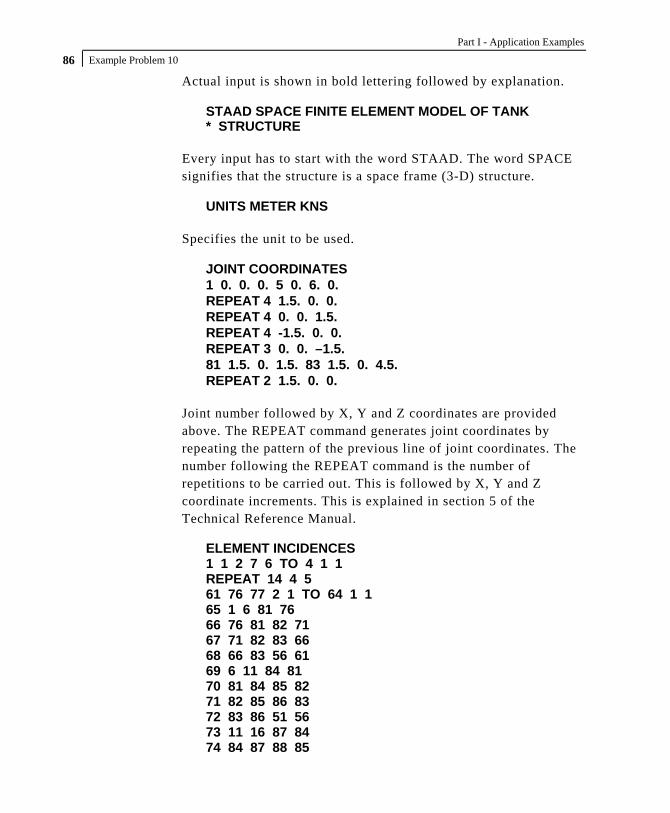
Part I - Application Examples Example Problem 10 86
Actual input is shown in bold lettering followed by explanation. STAAD SPACE FINITE ELEMENT MODEL OF TANK * STRUCTURE
Every input has to start with the word STAAD. The word SPACE signifies that the structure is a space frame (3-D) structure.
UNITS METER KNS
Specifies the unit to be used. JOINT COORDINATES 1 0. 0. 0. 5 0. 6. 0. REPEAT 4 1.5. 0. 0. REPEAT 4 0. 0. 1.5. REPEAT 4 -1.5. 0. 0. REPEAT 3 0. 0. –1.5. 81 1.5. 0. 1.5. 83 1.5. 0. 4.5. REPEAT 2 1.5. 0. 0.
Joint number followed by X, Y and Z coordinates are provided above. The REPEAT command generates joint coordinates by repeating the pattern of the previous line of joint coordinates. The number following the REPEAT command is the number of repetitions to be carried out. This is followed by X, Y and Z coordinate increments. This is explained in section 5 of the Technical Reference Manual.
ELEMENT INCIDENCES 1 1 2 7 6 TO 4 1 1 REPEAT 14 4 5 61 76 77 2 1 TO 64 1 1 65 1 6 81 76 66 76 81 82 71 67 71 82 83 66 68 66 83 56 61 69 6 11 84 81 70 81 84 85 82 71 82 85 86 83 72 83 86 51 56 73 11 16 87 84 74 84 87 88 85
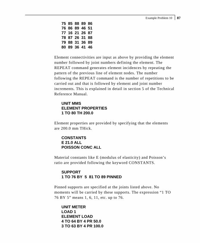
Example Problem 10 87 75 85 88 89 86 76 86 89 46 51 77 16 21 26 87 78 87 26 31 88 79 88 31 36 89 80 89 36 41 46
Element connectivities are input as above by providing the element number followed by joint numbers defining the element. The REPEAT command generates element incidences by repeating the pattern of the previous line of element nodes. The number following the REPEAT command is the number of repetitions to be carried out and that is followed by element and joint number increments. This is explained in detail in section 5 of the Technical Reference Manual.
UNIT MMS ELEMENT PROPERTIES 1 TO 80 TH 200.0
Element properties are provided by specifying that the elements are 200.0 mm THick.
CONSTANTS E 21.0 ALL POISSON CONC ALL
Material constants like E (modulus of elasticity) and Poisson’s ratio are provided following the keyword CONSTANTS.
SUPPORT 1 TO 76 BY 5 81 TO 89 PINNED
Pinned supports are specified at the joints listed above. No moments will be carried by these supports. The expression “1 TO 76 BY 5” means 1, 6, 11, etc. up to 76.
UNIT METER LOAD 1 ELEMENT LOAD 4 TO 64 BY 4 PR 50.0 3 TO 63 BY 4 PR 100.0

Part I - Application Examples Example Problem 10 88
2 TO 62 BY 4 PR 150.0 1 TO 61 BY 4 PR 200.0
Load case 1 is initiated. It consists of element loads in the form of uniform PRessure acting along the local z-axis.
PERFORM ANALYSIS
This command instructs the program to proceed with the analysis. UNIT MMS PRINT JOINT DISPLACEMENTS LIST 5 25 45 65 PRINT ELEM FORCE LIST 9 TO 16
Joint displacements for a selected set of nodes and element corner forces for some elements are written in the output file as a result of the above commands. The forces printed are in the global directions at the nodes of the elements. The LIST option restricts the print output to that for the joints/elements listed.
START CONCRETE DESIGN
The above command initiates concrete design. CODE BRITISH DESIGN SLAB 9 12
Slabs (i.e. elements) 9 and 12 will be designed and the reinforcement requirements obtained. In STAAD, elements are typically designed for the moments MX and MY at the centroid of the element.
END CONCRETE DESIGN
Terminates the concrete design operation. FINISH
This command terminates the STAAD run.

Example Problem 10 89
**************************************************** * * * STAAD.Pro * * Version 2007 Build 02 * * Proprietary Program of * * Research Engineers, Intl. * * Date= * * Time= * * * * USER ID: * **************************************************** 1. STAAD SPACE FINITE ELEMENT MODEL OF TANK 2. * STRUCTURE 3. UNITS METER KNS 4. JOINT COORDINATES 5. 1 0. 0. 0. 5 0. 6. 0. 6. REPEAT 4 1.5 0. 0. 7. REPEAT 4 0. 0. 1.5 8. REPEAT 4 -1.5 0. 0. 9. REPEAT 3 0. 0. -1.5 10. 81 1.5 0. 1.5 83 1.5 0. 4.5 11. REPEAT 2 1.5 0. 0. 12. ELEMENT INCIDENCES 13. 1 1 2 7 6 TO 4 1 1 14. REPEAT 14 4 5 15. 61 76 77 2 1 TO 64 1 1 16. 65 1 6 81 76 17. 66 76 81 82 71 18. 67 71 82 83 66 19. 68 66 83 56 61 20. 69 6 11 84 81 21. 70 81 84 85 82 22. 71 82 85 86 83 23. 72 83 86 51 56 24. 73 11 16 87 84 25. 74 84 87 88 85 26. 75 85 88 89 86 27. 76 86 89 46 51 28. 77 16 21 26 87 29. 78 87 26 31 88 30. 79 88 31 36 89 31. 80 89 36 41 46 32. UNIT MMS 33. ELEMENT PROPERTIES 34. 1 TO 80 TH 200.0 35. CONSTANTS 36. E 21.0 ALL 37. POISSON CONC ALL 38. SUPPORT 39. 1 TO 76 BY 5 81 TO 89 PINNED 40. UNIT METER 41. LOAD 1 42. ELEMENT LOAD 43. 4 TO 64 BY 4 PR 50.0 44. 3 TO 63 BY 4 PR 100.0 45. 2 TO 62 BY 4 PR 150.0 46. 1 TO 61 BY 4 PR 200.0 47. PERFORM ANALYSIS P R O B L E M S T A T I S T I C S ----------------------------------- NUMBER OF JOINTS/MEMBER+ELEMENTS/SUPPORTS = 89/ 80/ 25 SOLVER USED IS THE IN-CORE ADVANCED SOLVER TOTAL PRIMARY LOAD CASES = 1, TOTAL DEGREES OF FREEDOM = 459 48. UNIT MMS 49. PRINT JOINT DISPLACEMENTS LIST 5 25 45 65

Part I - Application Examples Example Problem 10 90
JOINT DISPLACEMENT (CM RADIANS) STRUCTURE TYPE = SPACE ------------------ JOINT LOAD X-TRANS Y-TRANS Z-TRANS X-ROTAN Y-ROTAN Z-ROTAN 5 1 -0.0103 0.0006 -0.0103 0.0002 0.0000 -0.0002 25 1 0.0103 0.0006 -0.0103 0.0002 0.0000 0.0002 45 1 0.0103 0.0006 0.0103 -0.0002 0.0000 0.0002 65 1 -0.0103 0.0006 0.0103 -0.0002 0.0000 -0.0002 ************** END OF LATEST ANALYSIS RESULT ************** 50. PRINT ELEM FORCE LIST 9 TO 16 ELEMENT FORCES FORCE,LENGTH UNITS= KNS MMS -------------- GLOBAL CORNER FORCES JOINT FX FY FZ MX MY MZ ELE.NO. 9 FOR LOAD CASE 1 11 -8.8359E+01 -5.3753E+01 1.8154E+02 1.3170E+05 -4.0959E+04 1.0868E+04 12 -8.4106E+01 -6.1780E+00 -1.5632E+02 7.9661E+04 5.9853E+04 -1.7299E+04 17 1.4404E+02 4.6568E+01 -1.6787E+02 1.2673E+05 -1.0931E+05 2.2151E+04 16 2.8428E+01 1.3363E+01 1.4265E+02 1.4820E+05 5.2581E+04 -1.5720E+04 ELE.NO. 10 FOR LOAD CASE 1 12 -1.8792E+02 6.1780E+00 -4.0552E+01 -7.9661E+04 1.0833E+05 4.7652E+04 13 -2.0044E+02 -3.6136E+01 -6.3740E+01 6.9905E+04 1.0284E+05 -5.8259E+04 18 2.3039E+02 -1.4028E+01 3.0854E+01 5.8249E+04 -5.3646E+04 6.1978E+04 17 1.5797E+02 4.3985E+01 7.3437E+01 8.3445E+02 -1.0826E+03 -5.1372E+04 ELE.NO. 11 FOR LOAD CASE 1 13 -2.1198E+02 3.6136E+01 -7.6885E+01 -6.9905E+04 1.2229E+05 5.7388E+04 14 -2.3157E+02 -1.4563E+01 -2.4018E+01 2.6342E+04 1.0499E+05 -6.4697E+04 19 2.0999E+02 -3.2387E+01 8.4179E+01 -1.5610E+04 -2.4207E+04 6.5236E+04 18 2.3355E+02 1.0814E+01 1.6725E+01 -3.1068E+04 -5.1714E+04 -5.7927E+04 ELE.NO. 12 FOR LOAD CASE 1 14 -1.7545E+02 1.4563E+01 -6.0357E+01 -2.6342E+04 1.0566E+05 4.3868E+04 15 -1.7875E+02 -1.1918E-06 -2.8125E+01 8.0227E-04 9.6044E+04 -4.9015E+04 20 1.6418E+02 -2.4213E+00 6.5563E+01 -2.8717E+04 -2.4535E+04 4.5288E+04 19 1.9002E+02 -1.2142E+01 2.2919E+01 -1.0980E+03 -4.4444E+04 -4.0140E+04 ELE.NO. 13 FOR LOAD CASE 1 16 -1.0527E+02 -8.1796E+01 -1.6646E+01 -1.3732E+04 2.6331E+04 1.5180E+04 17 -3.5139E+01 -6.7286E+01 -7.8110E+01 -7.8741E+03 -3.1163E+03 -2.4809E+04 22 1.8422E+02 2.6896E+01 8.1528E+01 -1.7008E+04 6.2736E+04 3.0020E+04 21 -4.3809E+01 1.2219E+02 1.3228E+01 3.3487E+04 5.6183E+04 -2.0392E+04 ELE.NO. 14 FOR LOAD CASE 1 17 -2.6686E+02 -2.3267E+01 -2.2121E+02 -1.1969E+05 1.1350E+05 5.4029E+04 18 -2.5280E+02 -5.3068E+00 -1.4951E+02 3.3215E+04 5.0983E+04 -5.3096E+04 23 2.8137E+02 5.5470E+01 2.2661E+02 -8.0444E+04 2.0370E+05 6.3346E+04 22 2.3829E+02 -2.6896E+01 1.4411E+02 5.1267E+04 1.8790E+05 -6.4279E+04 ELE.NO. 15 FOR LOAD CASE 1 18 -2.1115E+02 8.5202E+00 -1.7932E+02 -6.0396E+04 5.4377E+04 4.9044E+04 19 -2.3106E+02 2.8931E+01 -1.4843E+02 4.3665E+04 4.6709E+04 -5.2522E+04 24 1.9361E+02 1.8019E+01 1.6502E+02 -7.1533E+04 1.9615E+05 4.9770E+04 23 2.4860E+02 -5.5470E+01 1.6273E+02 6.3390E+04 1.9439E+05 -4.6292E+04 ELE.NO. 16 FOR LOAD CASE 1 19 -1.6895E+02 1.5597E+01 -1.2741E+02 -2.6957E+04 2.1943E+04 2.7426E+04 20 -1.6418E+02 2.4213E+00 -1.2181E+02 2.8717E+04 2.4535E+04 -4.5288E+04 25 1.4616E+02 -1.4829E-06 1.1804E+02 -5.5252E+04 1.6211E+05 5.5252E+04 24 1.8697E+02 -1.8019E+01 1.3119E+02 5.9154E+04 1.6525E+05 -3.7391E+04

Example Problem 10 91 51. START CONCRETE DESIGN 52. CODE BRITISH PROGRAM CODE REVISION V1.5_8110_97/1 53. DESIGN SLAB 9 12 ELEMENT DESIGN SUMMARY-BASED ON 16mm BARS ----------------------------------------- MINIMUM AREAS ARE ACTUAL CODE MIN % REQUIREMENTS. PRACTICAL LAYOUTS ARE AS FOLLOWS: FY=460, 6No.16mm BARS AT 150mm C/C = 1206mm2/metre FY=250, 4No.16mm BARS AT 250mm C/C = 804mm2/metre ELEMENT LONG. REINF MOM-X /LOAD TRANS. REINF MOM-Y /LOAD (mm2/m) (kN-m/m) (mm2/m) (kN-m/m) 9 TOP : 260. 0.00 / 0 387. 25.21 / 1 BOTT: 341. -24.51 / 1 260. 0.00 / 0 12 TOP : 260. 0.00 / 0 1570. 90.23 / 1 BOTT: 260. -0.43 / 1 260. 0.00 / 0 ***************************END OF ELEMENT DESIGN************************** 54. END CONCRETE DESIGN 55. FINISH *********** END OF THE STAAD.Pro RUN *********** **** DATE= TIME= **** ************************************************************ * For questions on STAAD.Pro, please contact * * Research Engineers Offices at the following locations * * * * Telephone Email * * USA: +1 (714)974-2500 [email protected] * * CANADA +1 (905)632-4771 [email protected] * * UK +44(1454)207-000 [email protected] * * FRANCE +33(0)1 64551084 [email protected] * * GERMANY +49/931/40468-71 [email protected] * * NORWAY +47 67 57 21 30 [email protected] * * SINGAPORE +65 6225-6158 [email protected] * * INDIA +91(033)4006-2021 [email protected] * * JAPAN +81(03)5952-6500 [email protected] * * CHINA +86(411)363-1983 [email protected] * * THAILAND +66(0)2645-1018/19 [email protected] * * * * North America [email protected] * * Europe [email protected] * * Asia [email protected] * ************************************************************

Part I - Application Examples Example Problem 10 92
NOTES

Example Problem 11 93
Example Problem No. 11
Dynamic analysis (Response Spectrum) is performed for a steel structure. Results of a static and dynamic analysis are combined. The combined results are then used for steel design.

Part I - Application Examples Example Problem 11 94
Actual input is shown in bold lettering followed by explanation. STAAD PLANE RESPONSE SPECTRUM ANALYSIS
Every input has to start with the word STAAD. The word PLANE signifies that the structure is a plane frame structure and the geometry is defined through X and Y axes.
UNIT METER KNS
Specifies the unit to be used. JOINT COORDINATES 1 0.0 0.0 0.0 ; 2 6.0 0.0 0.0 3 0.0 3.0 0.0 ; 4 6.0 3.0 0.0 5 0.0 6.0 0.0 ; 6 6.0 6.0 0.0
Joint number followed by X, Y and Z coordinates are provided above. Since this is a plane structure, the Z coordinates are all the same, in this case, zeros. Semicolon signs (;) are used as line separators to allow for input of multiple sets of data on one line.
MEMBER INCIDENCES 1 1 3 ; 2 2 4 ; 3 3 5 ; 4 4 6 5 3 4 ; 6 5 6
Defines the members by the joints they are connected to. MEMBER PROPERTIES BRITISH 1 TO 4 TA ST UC254X254X73 5 TA ST UB305X165X54 6 TA ST UB203X133X30
Properties for all members are assigned from the British steel table. The word ST stands for standard single section.
SUPPORTS 1 2 FIXED
Fixed supports are specified at joints 1 and 2.

Example Problem 11 95
UNIT MMS CONSTANTS E 210.0 ALL POISSON STEEL ALL DEN 76.977E-09 ALL
Material constants such as E (modulus of elasticity), Poisson’s ratio and DENsity are specified above. Length unit is changed from METER to MMS to facilitate the input.
CUT OFF MODE SHAPE 2
The number of mode shapes to be considered in dynamic analysis is set to 2. Without the above command, this will be set to the default which can be found in section 5 of the Technical Reference Manual.
* LOAD 1 WILL BE STATIC LOAD UNIT METER LOAD 1 DEAD AND LIVE LOADS
Load case 1 is initiated followed by a title. Prior to this, the length unit is changed to METER for specifying distributed member loads. A line starting with an asterisk (*) mark indicates a comment line.
SELFWEIGHT Y -1.0
The above command indicates that the selfweight of the structure acting in the global Y direction is part of this load case. The factor of -1.0 is meant to indicate that the load acts opposite to the positive direction of global Y, hence downwards.
MEMBER LOADS 5 CON GY -25.0 1.8 5 CON GY -37.5 3.0 5 CON GY -25.0 4.2 5 6 UNI Y -22.5
Load 1 contains member loads also. GY indicates that the load is in the global Y direction while Y indicates local Y direction. The

Part I - Application Examples Example Problem 11 96
word UNI stands for uniformly distributed load while CON stands for concentrated load. GY is followed by the value of the load and the distance at which it is applied.
* NEXT LOAD WILL BE RESPONSE SPECTRUM LOAD * WITH MASSES PROVIDED IN TERMS OF LOAD. LOAD 2 SEISMIC LOADING
The two lines which begin with the asterisk are comment lines which tell us the purpose of the next load case. Load case 2 is then initiated along with an optional title. This will be a dynamic load case. Permanent masses will be provided in the form of loads. These masses (in terms of loads) will be considered for the eigensolution. Internally, the program converts these loads to masses, hence it is best to specify them as absolute values (without a negative sign). Also, the direction (X, Y, Z etc.) of the loads will correspond to the dynamic degrees of freedom in which the masses are capable of vibrating. In a PLANE frame, only X and Y directions need to be considered. In a SPACE frame, masses (loads) should be provided in all three (X, Y and Z) directions if they are active along all three. The user has the freedom to restrict one or more directions.
SELFWEIGHT X 1.0 SELFWEIGHT Y 1.0
The above commands indicate that the selfweight of the structure acting in the global X and Y directions with a factor of 1.0 is taken into consideration for the mass matrix.
MEMBER LOADS 5 CON GX 25.0 1.8 5 CON GY 25.0 1.8 5 CON GX 37.5 3.0 5 CON GY 37.5 3.0 5 CON GX 25.0 4.2 5 CON GY 25.0 4.2
The mass matrix will also consist of terms derived from the above member loads. GX and GY indicate that the load, and hence the resulting mass, is capable of vibration along the global X and Y

Example Problem 11 97
directions. The word CON stands for concentrated load. Concentrated forces of 25, 37.5, and 25 kNs are located at 1.8m, 3.0m and 4.2m from the start of member 5.
SPECTRUM CQC X 1.0 ACC DAMP 0.05 SCALE 9.806 0.03 1.00 ; 0.05 1.35 0.1 1.95 ; 0.2 2.80 0.5 2.80 ; 1.0 1.60
The above SPECTRUM command specifies that the modal responses be combined using the CQC method (alternatives being the SRSS method, ABS method, etc.). The spectrum effect is in the global X direction with a factor of 1.0. Since this spectrum is in terms of ACCeleration (the other possibility being displacement), the spectrum data is given as period vs. acceleration. Damping ratio of 0.05 (5%) and a scale factor of 9.806 are used. The scale factor is the quantity by which spectral accelerations (and spectral displacements) must be multiplied by before they are used in the calculations. The values of periods and the corresponding accelerations are given in the last 3 lines.
LOAD COMBINATION 3 1 0.75 2 0.75 LOAD COMBINATION 4 1 0.75 2 -0.75
In a response spectrum analysis, the sign of the forces cannot be determined, and hence are absolute numbers. Consequently, to account for the fact that the force could be positive or negative, it is necessary to create 2 load combination cases. That is what is being done above. Load combination case no. 3 consists of the sum of the static load case (1) with the positive direction of the dynamic load case (2). Load combination case no. 4 consists of the sum of the static load case (1) with the negative direction of the dynamic load case (2). In both cases, the result is factored by 0.75.
PERFORM ANALYSIS PRINT MODE SHAPES

Part I - Application Examples Example Problem 11 98
This command instructs the program to proceed with the analysis. The PRINT command instructs the program to print mode shape values.
PRINT ANALYSIS RESULTS
Displacements, reactions and member forces are recorded in the output file using the above command.
LOAD LIST 1 3 4 PARAMETER CODE BRITISH SELECT ALL
A steel design in the form of a member selection is performed based on the rules of the British code. Only the member forces resulting from load cases 1, 3 and 4 will be considered for these calculations.
FINISH
This command terminates the STAAD run.

Example Problem 11 99 **************************************************** * * * STAAD.Pro * * Version 2007 Build 02 * * Proprietary Program of * * Research Engineers, Intl. * * Date= * * Time= * * * * USER ID: * **************************************************** 1. STAAD PLANE RESPONSE SPECTRUM ANALYSIS 2. UNIT METER KNS 3. JOINT COORDINATES 4. 1 0.0 0.0 0.0 ; 2 6.0 0.0 0.0 5. 3 0.0 3.0 0.0 ; 4 6.0 3.0 0.0 6. 5 0.0 6.0 0.0 ; 6 6.0 6.0 0.0 7. MEMBER INCIDENCES 8. 1 1 3 ; 2 2 4 ; 3 3 5 ; 4 4 6 9. 5 3 4 ; 6 5 6 10. MEMBER PROPERTIES BRITISH 11. 1 TO 4 TA ST UC254X254X73 12. 5 TA ST UB305X165X54 13. 6 TA ST UB203X133X30 14. SUPPORTS 15. 1 2 FIXED 16. UNIT MMS 17. CONSTANTS 18. E 210.0 ALL 19. POISSON STEEL ALL 20. DEN 76.977E-09 ALL 21. CUT OFF MODE SHAPE 2 22. * LOAD 1 WILL BE STATIC LOAD 23. UNIT METER 24. LOAD 1 DEAD AND LIVE LOADS 25. SELFWEIGHT Y -1.0 26. MEMBER LOADS 27. 5 CON GY -25.0 1.8 28. 5 CON GY -37.5 3.0 29. 5 CON GY -25.0 4.2 30. 5 6 UNI Y -22.5 31. * NEXT LOAD WILL BE RESPONSE SPECTRUM LOAD 32. * WITH MASSES PROVIDED IN TERMS OF LOAD. 33. LOAD 2 SEISMIC LOADING 34. SELFWEIGHT X 1.0 35. SELFWEIGHT Y 1.0 36. MEMBER LOADS 37. 5 CON GX 25.0 1.8 38. 5 CON GY 25.0 1.8 39. 5 CON GX 37.5 3.0 40. 5 CON GY 37.5 3.0 41. 5 CON GX 25.0 4.2 42. 5 CON GY 25.0 4.2 43. SPECTRUM CQC X 1.0 ACC DAMP 0.05 SCALE 9.806 44. 0.03 1.00 ; 0.05 1.35 45. 0.1 1.95 ; 0.2 2.80 46. 0.5 2.80 ; 1.0 1.60 47. LOAD COMBINATION 3 48. 1 0.75 2 0.75 49. LOAD COMBINATION 4 50. 1 0.75 2 -0.75 51. PERFORM ANALYSIS PRINT MODE SHAPES P R O B L E M S T A T I S T I C S ----------------------------------- NUMBER OF JOINTS/MEMBER+ELEMENTS/SUPPORTS = 6/ 6/ 2 SOLVER USED IS THE IN-CORE ADVANCED SOLVER

Part I - Application Examples Example Problem 11 100
TOTAL PRIMARY LOAD CASES = 2, TOTAL DEGREES OF FREEDOM = 12 NUMBER OF MODES REQUESTED = 2 NUMBER OF EXISTING MASSES IN THE MODEL = 8 NUMBER OF MODES THAT WILL BE USED = 2 *** EIGENSOLUTION: ADVANCED METHOD *** CALCULATED FREQUENCIES FOR LOAD CASE 2 MODE FREQUENCY(CYCLES/SEC) PERIOD(SEC) 1 5.179 0.19308 2 19.437 0.05145 MODE SHAPES ----------- JOINT MODE X-TRANS Y-TRANS Z-TRANS X-ROTAN Y-ROTAN Z-ROTAN 1 1 0.00000 0.00000 0.00000 0.000E+00 0.000E+00 0.000E+00 2 1 0.00000 0.00000 0.00000 0.000E+00 0.000E+00 0.000E+00 3 1 0.58328 0.00218 0.00000 0.000E+00 0.000E+00 -3.863E-03 4 1 0.58328 -0.00218 0.00000 0.000E+00 0.000E+00 -3.863E-03 5 1 1.00000 0.00251 0.00000 0.000E+00 0.000E+00 -2.797E-03 6 1 1.00000 -0.00251 0.00000 0.000E+00 0.000E+00 -2.797E-03 MODE SHAPES ----------- JOINT MODE X-TRANS Y-TRANS Z-TRANS X-ROTAN Y-ROTAN Z-ROTAN 1 2 0.00000 0.00000 0.00000 0.000E+00 0.000E+00 0.000E+00 2 2 0.00000 0.00000 0.00000 0.000E+00 0.000E+00 0.000E+00 3 2 -0.07067 0.00282 0.00000 0.000E+00 0.000E+00 -2.798E-03 4 2 -0.07067 -0.00282 0.00000 0.000E+00 0.000E+00 -2.798E-03 5 2 1.00000 0.00400 0.00000 0.000E+00 0.000E+00 -9.742E-03 6 2 1.00000 -0.00400 0.00000 0.000E+00 0.000E+00 -9.742E-03 RESPONSE LOAD CASE 2 CQC MODAL COMBINATION METHOD USED. DYNAMIC WEIGHT X Y Z 9.889183E+01 9.889183E+01 0.000000E+00 KNS MISSING WEIGHT X Y Z -3.077470E-04 -9.889183E+01 0.000000E+00 KNS MODAL WEIGHT X Y Z 9.889152E+01 1.590301E-35 0.000000E+00 KNS MODE ACCELERATION-G DAMPING ---- -------------- ------- 1 2.74097 0.05000 2 1.36730 0.05000 MODAL BASE ACTIONS FORCES IN KNS LENGTH IN METE ----------------------------------------------------------- MOMENTS ARE ABOUT THE ORIGIN MODE PERIOD FX FY FZ MX MY MZ 1 0.193 266.17 0.00 0.00 0.00 0.00 -854.13 2 0.051 2.44 0.00 0.00 0.00 0.00 3.66

Example Problem 11 101 MASS PARTICIPATION FACTORS IN PERCENT BASE SHEAR IN KNS -------------------------------------- ------------------ MODE X Y Z SUMM-X SUMM-Y SUMM-Z X Y Z 1 98.20 0.00 0.00 98.197 0.000 0.000 266.17 0.00 0.00 2 1.80 0.00 0.00 100.000 0.000 0.000 2.44 0.00 0.00 --------------------------- TOTAL SRSS SHEAR 266.18 0.00 0.00 TOTAL 10PCT SHEAR 266.18 0.00 0.00 TOTAL ABS SHEAR 268.61 0.00 0.00 TOTAL CQC SHEAR 266.18 0.00 0.00 52. PRINT ANALYSIS RESULTS JOINT DISPLACEMENT (CM RADIANS) STRUCTURE TYPE = PLANE ------------------ JOINT LOAD X-TRANS Y-TRANS Z-TRANS X-ROTAN Y-ROTAN Z-ROTAN 1 1 0.0000 0.0000 0.0000 0.0000 0.0000 0.0000 2 0.0000 0.0000 0.0000 0.0000 0.0000 0.0000 3 0.0000 0.0000 0.0000 0.0000 0.0000 0.0000 4 0.0000 0.0000 0.0000 0.0000 0.0000 0.0000 2 1 0.0000 0.0000 0.0000 0.0000 0.0000 0.0000 2 0.0000 0.0000 0.0000 0.0000 0.0000 0.0000 3 0.0000 0.0000 0.0000 0.0000 0.0000 0.0000 4 0.0000 0.0000 0.0000 0.0000 0.0000 0.0000 3 1 -0.0042 -0.0283 0.0000 0.0000 0.0000 -0.0017 2 2.4239 0.0091 0.0000 0.0000 0.0000 0.0063 3 1.8148 -0.0144 0.0000 0.0000 0.0000 0.0035 4 -1.8211 -0.0280 0.0000 0.0000 0.0000 -0.0060 4 1 0.0042 -0.0283 0.0000 0.0000 0.0000 0.0017 2 2.4239 0.0091 0.0000 0.0000 0.0000 0.0063 3 1.8211 -0.0144 0.0000 0.0000 0.0000 0.0060 4 -1.8148 -0.0280 0.0000 0.0000 0.0000 -0.0035 5 1 0.0163 -0.0390 0.0000 0.0000 0.0000 -0.0017 2 4.1560 0.0104 0.0000 0.0000 0.0000 0.0046 3 3.1292 -0.0214 0.0000 0.0000 0.0000 0.0022 4 -3.1048 -0.0371 0.0000 0.0000 0.0000 -0.0047 6 1 -0.0163 -0.0390 0.0000 0.0000 0.0000 0.0017 2 4.1560 0.0104 0.0000 0.0000 0.0000 0.0046 3 3.1048 -0.0214 0.0000 0.0000 0.0000 0.0047 4 -3.1292 -0.0371 0.0000 0.0000 0.0000 -0.0022 SUPPORT REACTIONS -UNIT KNS METE STRUCTURE TYPE = PLANE ----------------- JOINT LOAD FORCE-X FORCE-Y FORCE-Z MOM-X MOM-Y MOM Z 1 1 23.48 185.52 0.00 0.00 0.00 -21.57 2 133.09 59.00 0.00 0.00 0.00 250.11 3 117.43 183.39 0.00 0.00 0.00 171.40 4 -82.21 94.89 0.00 0.00 0.00 -203.76 2 1 -23.48 185.52 0.00 0.00 0.00 21.57 2 133.09 59.00 0.00 0.00 0.00 250.11 3 82.21 183.39 0.00 0.00 0.00 203.76 4 -117.43 94.89 0.00 0.00 0.00 -171.40

Part I - Application Examples Example Problem 11 102
MEMBER END FORCES STRUCTURE TYPE = PLANE ----------------- ALL UNITS ARE -- KNS METE (LOCAL ) MEMBER LOAD JT AXIAL SHEAR-Y SHEAR-Z TORSION MOM-Y MOM-Z 1 1 1 185.52 -23.48 0.00 0.00 0.00 -21.57 3 -183.37 23.48 0.00 0.00 0.00 -48.85 2 1 59.00 133.09 0.00 0.00 0.00 250.11 3 59.00 133.09 0.00 0.00 0.00 149.17 3 1 183.39 82.21 0.00 0.00 0.00 171.40 3 -93.28 117.43 0.00 0.00 0.00 75.24 4 1 94.89 -117.43 0.00 0.00 0.00 -203.76 3 -181.78 -82.21 0.00 0.00 0.00 -148.52 2 1 2 185.52 23.48 0.00 0.00 0.00 21.57 4 -183.37 -23.48 0.00 0.00 0.00 48.85 2 2 59.00 133.09 0.00 0.00 0.00 250.11 4 59.00 133.09 0.00 0.00 0.00 149.17 3 2 183.39 117.43 0.00 0.00 0.00 203.76 4 -93.28 82.21 0.00 0.00 0.00 148.52 4 2 94.89 -82.21 0.00 0.00 0.00 -171.40 4 -181.78 -117.43 0.00 0.00 0.00 -75.24 3 1 3 70.53 -43.63 0.00 0.00 0.00 -65.87 5 -68.38 43.63 0.00 0.00 0.00 -65.03 2 3 9.07 8.95 0.00 0.00 0.00 3.88 5 9.07 8.95 0.00 0.00 0.00 27.13 3 3 59.70 -26.01 0.00 0.00 0.00 -46.49 5 -44.49 39.44 0.00 0.00 0.00 -28.42 4 3 46.10 -39.44 0.00 0.00 0.00 -52.32 5 -58.09 26.01 0.00 0.00 0.00 -69.12 4 1 4 70.53 43.63 0.00 0.00 0.00 65.87 6 -68.38 -43.63 0.00 0.00 0.00 65.03 2 4 9.07 8.95 0.00 0.00 0.00 3.88 6 9.07 8.95 0.00 0.00 0.00 27.13 3 4 59.70 39.44 0.00 0.00 0.00 52.32 6 -44.49 -26.01 0.00 0.00 0.00 69.12 4 4 46.10 26.01 0.00 0.00 0.00 46.49 6 -58.09 -39.44 0.00 0.00 0.00 28.42 5 1 3 -20.16 112.84 0.00 0.00 0.00 114.73 4 20.16 112.84 0.00 0.00 0.00 -114.73 2 3 0.00 49.47 0.00 0.00 0.00 148.41 4 0.00 49.47 0.00 0.00 0.00 148.41 3 3 -15.12 121.73 0.00 0.00 0.00 197.35 4 15.12 121.73 0.00 0.00 0.00 25.26 4 3 -15.12 47.53 0.00 0.00 0.00 -25.26 4 15.12 47.53 0.00 0.00 0.00 -197.35 6 1 5 43.63 68.38 0.00 0.00 0.00 65.03 6 -43.63 68.38 0.00 0.00 0.00 -65.03 2 5 0.00 9.04 0.00 0.00 0.00 27.13 6 0.00 9.04 0.00 0.00 0.00 27.13 3 5 32.73 58.07 0.00 0.00 0.00 69.12 6 -32.73 58.07 0.00 0.00 0.00 -28.42 4 5 32.73 44.50 0.00 0.00 0.00 28.42 6 -32.73 44.50 0.00 0.00 0.00 -69.12 ************** END OF LATEST ANALYSIS RESULT ************** 53. LOAD LIST 1 3 4 54. PARAMETER 55. CODE BRITISH 56. SELECT ALL
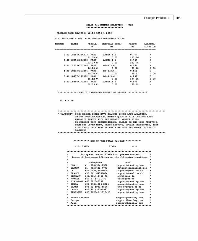
Example Problem 11 103 STAAD.Pro MEMBER SELECTION - (BSI ) ************************** PROGRAM CODE REVISION V2.10_5950-1_2000 ALL UNITS ARE - KNS METE (UNLESS OTHERWISE NOTED) MEMBER TABLE RESULT/ CRITICAL COND/ RATIO/ LOADING/ FX MY MZ LOCATION ======================================================================= 1 ST UC254X254X73 PASS ANNEX I.1 0.767 4 181.78 C 0.00 203.76 - 2 ST UC254X254X73 PASS ANNEX I.1 0.767 3 183.39 C 0.00 203.76 - 3 ST UC203X203X46 PASS BS-4.3.6 0.551 4 46.10 C 0.00 69.12 0.00 4 ST UC203X203X46 PASS BS-4.3.6 0.551 3 59.70 C 0.00 69.12 0.00 5 ST UB457X191X82 PASS BS-4.3.6 0.898 3 15.12 T 0.00 197.35 0.00 6 ST UB356X171X45 PASS ANNEX I.1 0.979 4 32.73 C 0.00 69.12 - ************** END OF TABULATED RESULT OF DESIGN ************** 57. FINISH **************************************************************************** **WARNING** SOME MEMBER SIZES HAVE CHANGED SINCE LAST ANALYSIS. IN THE POST PROCESSOR, MEMBER QUERIES WILL USE THE LAST ANALYSIS FORCES WITH THE UPDATED MEMBER SIZES. TO CORRECT THIS INCONSISTENCY, PLEASE DO ONE MORE ANALYSIS. FROM THE UPPER MENU, PRESS RESULTS, UPDATE PROPERTIES, THEN FILE SAVE; THEN ANALYZE AGAIN WITHOUT THE GROUP OR SELECT COMMANDS. **************************************************************************** *********** END OF THE STAAD.Pro RUN *********** **** DATE= TIME= **** ************************************************************ * For questions on STAAD.Pro, please contact * * Research Engineers Offices at the following locations * * * * Telephone Email * * USA: +1 (714)974-2500 [email protected] * * CANADA +1 (905)632-4771 [email protected] * * UK +44(1454)207-000 [email protected] * * FRANCE +33(0)1 64551084 [email protected] * * GERMANY +49/931/40468-71 [email protected] * * NORWAY +47 67 57 21 30 [email protected] * * SINGAPORE +65 6225-6158 [email protected] * * INDIA +91(033)4006-2021 [email protected] * * JAPAN +81(03)5952-6500 [email protected] * * CHINA +86(411)363-1983 [email protected] * * THAILAND +66(0)2645-1018/19 [email protected] * * * * North America [email protected] * * Europe [email protected] * * Asia [email protected] * ************************************************************

Part I - Application Examples Example Problem 11 104
NOTES

Example Problem 12 105
Example Problem No. 12
This example demonstrates generation of load cases for the type of loading known as a moving load. This type of loading occurs classically when the load-causing units move on the structure, as in the case of trucks on a bridge deck. The mobile loads are discretized into several individual immobile load cases at discrete positions. During this process, enormous number of load cases may be created resulting in plenty of output to be sorted. To avoid looking into a lot of output, the maximum force envelope is requested for a few specific members.

Part I - Application Examples Example Problem 12 106
Actual input is shown in bold lettering followed by explanation. STAAD FLOOR A SIMPLE BRIDGE DECK
Every input has to start with the word STAAD. The word FLOOR signifies that the structure is a floor structure and the geometry is defined through X and Z axis.
UNITS METER KNS
Specifies the unit to be used. JOINT COORDINATES 1 0 0 0 6 7.5 0 0 R 5 0 0 9.0
Joint number followed by X, Y and Z coordinates are provided above. Since this is a floor structure, the Y coordinates are all the same, in this case, zeros. The first line generates joints 1 through 6. With the repeat (R) command, the coordinates of the next 30 joints are generated by repeating the pattern of the coordinates of the first 6 joints 5 times with X, Y and Z increments of 0,0 & 9 respectively.
MEMBER INCIDENCES 1 1 7 6 7 1 2 11 R A 4 11 6 56 31 32 60
Defines the members by the joints they are connected to. The fourth number indicates the final member number upto which they will be generated. Repeat all (abbreviated as R A) will create members by repeating the member incidence pattern of the previous 11 members. The number of repetitions to be carried out is provided after the R A command and the member increment and joint increment are defined as 11 and 6 respectively. The fifth line of input defines the member incidences for members 56 to 60.
MEMBER PROPERTIES BRITISH 1 TO 60 TA ST UB305X165X40

Example Problem 12 107
Properties for all members are assigned from the British steel table. The word ST stands for standard single section.
SUPPORTS 1 TO 6 31 TO 36 PINNED
Pinned supports are specified at the above joints. A pinned support is one which can resist only translational forces.
UNITS MMS CONSTANTS E 210.0 ALL POISSON STEEL ALL DEN 76.977E-09 ALL UNIT METER KNS
Material constants like E (modulus of elasticity), Poisson’s ratio and DENsity are specified above following a change in the units of length from METER to MMS.
DEFINE MOVING LOAD TYPE 1 LOAD 90.0 90.0 45.0 DISTANCE 3.0 1.5 WIDTH 3.0
The characteristics of the vehicle are defined above in METER and KNS units. The above lines represent the first out of two sets of data required in moving load generation. The type number (1) is a label for identification of the load-causing unit, such as a truck. 3 axles (90 90 45) are specified with the LOAD command. The spacing between the axles in the direction of movement (longitudinal direction) is specified after the DISTANCE command. WIDTH is the spacing in the transverse direction, that is, it is the distance between the 2 prongs of an axle of the truck.
LOAD 1
Load case 1 is initiated. SELF Y -1.0

Part I - Application Examples Example Problem 12 108
Selfweight of the structure acting in the negative (due to the factor -1.0) global Y direction is the only component of load case 1.
LOAD GENERATION 10 TYPE 1 2.25 0. 0. ZI 3.0
This constitutes the second of the two sets of data required for moving load generation. 10 load cases are generated using the Type 1 vehicle whose characteristics were described earlier. For the first of these load cases, the X, Y and Z location of the reference load (see section 5.31.1 of the Technical Reference Manual) have been specified after the command TYPE 1. The Z Increment of 3.0m denotes that the vehicle moves along the Z direction and the individual positions which are 3.0m apart will be used to generate the remaining 9 load cases.
PERFORM ANALYSIS PRINT LOAD
The above command instructs the program to proceed with the analysis and print the values and positions of all the generated load cases.
PRINT MAXFORCE ENVELOP LIST 3 41 42
A maximum force envelope consisting of the highest forces for each degree of freedom on the listed members will be written into the output file.
FINISH
This command terminates the STAAD run.

Example Problem 12 109 **************************************************** * * * STAAD.Pro * * Version 2007 Build 02 * * Proprietary Program of * * Research Engineers, Intl. * * Date= * * Time= * * * * USER ID: * **************************************************** 1. STAAD FLOOR A SIMPLE BRIDGE DECK 2. UNITS METER KNS 3. JOINT COORDINATES 4. 1 0 0 0 6 7.5 0 0 5. R 5 0 0 9.0 6. MEMBER INCIDENCES 7. 1 1 7 6 8. 7 1 2 11 9. R A 4 11 6 10. 56 31 32 60 11. MEMBER PROPERTIES BRITISH 12. 1 TO 60 TA ST UB305X165X40 13. SUPPORTS 14. 1 TO 6 31 TO 36 PINNED 15. UNITS MMS 16. CONSTANTS 17. E 210.0 ALL 18. POISSON STEEL ALL 19. DEN 76.977E-09 ALL 20. UNIT METER KNS 21. DEFINE MOVING LOAD 22. TYPE 1 LOAD 90.0 90.0 45.0 23. DISTANCE 3.0 1.5 WIDTH 3.0 24. LOAD 1 25. SELF Y -1.0 26. LOAD GENERATION 10 27. TYPE 1 2.25 0. 0. ZI 3.0 28. PERFORM ANALYSIS PRINT LOAD P R O B L E M S T A T I S T I C S ----------------------------------- NUMBER OF JOINTS/MEMBER+ELEMENTS/SUPPORTS = 36/ 60/ 12 SOLVER USED IS THE IN-CORE ADVANCED SOLVER TOTAL PRIMARY LOAD CASES = 11, TOTAL DEGREES OF FREEDOM = 96 LOADING 1 ----------- SELFWEIGHT Y -1.000 ACTUAL WEIGHT OF THE STRUCTURE = 124.391 KNS LOADING 2 ----------- MEMBER LOAD - UNIT KNS METE MEMBER UDL L1 L2 CON L LIN1 LIN2 8 -90.0000 GY 0.75 10 -90.0000 GY 0.75 3 -45.0000 GY 3.00 2 -45.0000 GY 3.00 5 -45.0000 GY 3.00 4 -45.0000 GY 3.00 3 -22.5000 GY 4.50 2 -22.5000 GY 4.50 5 -22.5000 GY 4.50 4 -22.5000 GY 4.50

Part I - Application Examples Example Problem 12 110
LOADING 3 ----------- MEMBER LOAD - UNIT KNS METE MEMBER UDL L1 L2 CON L LIN1 LIN2 3 -45.0000 GY 3.00 2 -45.0000 GY 3.00 5 -45.0000 GY 3.00 4 -45.0000 GY 3.00 3 -45.0000 GY 6.00 2 -45.0000 GY 6.00 5 -45.0000 GY 6.00 4 -45.0000 GY 6.00 3 -22.5000 GY 7.50 2 -22.5000 GY 7.50 5 -22.5000 GY 7.50 4 -22.5000 GY 7.50 LOADING 4 ----------- MEMBER LOAD - UNIT KNS METE MEMBER UDL L1 L2 CON L LIN1 LIN2 3 -45.0000 GY 6.00 2 -45.0000 GY 6.00 5 -45.0000 GY 6.00 4 -45.0000 GY 6.00 19 -90.0000 GY 0.75 21 -90.0000 GY 0.75 14 -22.5000 GY 1.50 13 -22.5000 GY 1.50 16 -22.5000 GY 1.50 15 -22.5000 GY 1.50 LOADING 5 ----------- MEMBER LOAD - UNIT KNS METE MEMBER UDL L1 L2 CON L LIN1 LIN2 19 -90.0000 GY 0.75 21 -90.0000 GY 0.75 14 -45.0000 GY 3.00 13 -45.0000 GY 3.00 16 -45.0000 GY 3.00 15 -45.0000 GY 3.00 14 -22.5000 GY 4.50 13 -22.5000 GY 4.50 16 -22.5000 GY 4.50 15 -22.5000 GY 4.50 LOADING 6 ----------- MEMBER LOAD - UNIT KNS METE MEMBER UDL L1 L2 CON L LIN1 LIN2 14 -45.0000 GY 3.00 13 -45.0000 GY 3.00 16 -45.0000 GY 3.00 15 -45.0000 GY 3.00 14 -45.0000 GY 6.00 13 -45.0000 GY 6.00 16 -45.0000 GY 6.00 15 -45.0000 GY 6.00 14 -22.5000 GY 7.50 13 -22.5000 GY 7.50 16 -22.5000 GY 7.50 15 -22.5000 GY 7.50
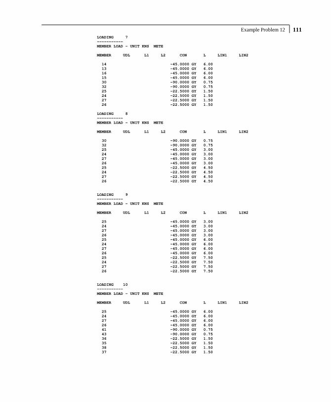
Example Problem 12 111 LOADING 7 ----------- MEMBER LOAD - UNIT KNS METE MEMBER UDL L1 L2 CON L LIN1 LIN2 14 -45.0000 GY 6.00 13 -45.0000 GY 6.00 16 -45.0000 GY 6.00 15 -45.0000 GY 6.00 30 -90.0000 GY 0.75 32 -90.0000 GY 0.75 25 -22.5000 GY 1.50 24 -22.5000 GY 1.50 27 -22.5000 GY 1.50 26 -22.5000 GY 1.50 LOADING 8 ----------- MEMBER LOAD - UNIT KNS METE MEMBER UDL L1 L2 CON L LIN1 LIN2 30 -90.0000 GY 0.75 32 -90.0000 GY 0.75 25 -45.0000 GY 3.00 24 -45.0000 GY 3.00 27 -45.0000 GY 3.00 26 -45.0000 GY 3.00 25 -22.5000 GY 4.50 24 -22.5000 GY 4.50 27 -22.5000 GY 4.50 26 -22.5000 GY 4.50 LOADING 9 ----------- MEMBER LOAD - UNIT KNS METE MEMBER UDL L1 L2 CON L LIN1 LIN2 25 -45.0000 GY 3.00 24 -45.0000 GY 3.00 27 -45.0000 GY 3.00 26 -45.0000 GY 3.00 25 -45.0000 GY 6.00 24 -45.0000 GY 6.00 27 -45.0000 GY 6.00 26 -45.0000 GY 6.00 25 -22.5000 GY 7.50 24 -22.5000 GY 7.50 27 -22.5000 GY 7.50 26 -22.5000 GY 7.50 LOADING 10 ----------- MEMBER LOAD - UNIT KNS METE MEMBER UDL L1 L2 CON L LIN1 LIN2 25 -45.0000 GY 6.00 24 -45.0000 GY 6.00 27 -45.0000 GY 6.00 26 -45.0000 GY 6.00 41 -90.0000 GY 0.75 43 -90.0000 GY 0.75 36 -22.5000 GY 1.50 35 -22.5000 GY 1.50 38 -22.5000 GY 1.50 37 -22.5000 GY 1.50

Part I - Application Examples Example Problem 12 112
LOADING 11 ----------- MEMBER LOAD - UNIT KNS METE MEMBER UDL L1 L2 CON L LIN1 LIN2 41 -90.0000 GY 0.75 43 -90.0000 GY 0.75 36 -45.0000 GY 3.00 35 -45.0000 GY 3.00 38 -45.0000 GY 3.00 37 -45.0000 GY 3.00 36 -22.5000 GY 4.50 35 -22.5000 GY 4.50 38 -22.5000 GY 4.50 37 -22.5000 GY 4.50 ************ END OF DATA FROM INTERNAL STORAGE ************ 29. PRINT MAXFORCE ENVELOP LIST 3 41 42 MEMBER FORCE ENVELOPE --------------------- ALL UNITS ARE KNS METE MAX AND MIN FORCE VALUES AMONGST ALL SECTION LOCATIONS MEMB FY/ DIST LD MZ/ DIST LD FZ DIST LD MY DIST LD FX DIST LD 3 MAX 81.16 0.00 3 0.03 0.00 4 0.00 0.00 1 0.00 0.00 1 0.00 0.00 1 MIN -31.34 9.00 3 -504.76 9.00 5 0.00 9.00 11 0.00 9.00 11 0.00 9.00 11 41 MAX 73.48 0.00 10 9.18 1.50 5 0.00 0.00 1 0.00 0.00 1 0.00 0.00 1 MIN -18.36 1.50 11 -147.24 0.75 10 0.00 1.50 11 0.00 1.50 11 0.00 1.50 11 42 MAX 0.30 0.00 1 9.17 0.00 5 0.00 0.00 1 0.00 0.00 1 0.00 0.00 1 MIN -0.30 1.50 1 -134.84 1.50 10 0.00 1.50 11 0.00 1.50 11 0.00 1.50 11 ********** END OF FORCE ENVELOPE FROM INTERNAL STORAGE ********** 30. FINISH *********** END OF THE STAAD.Pro RUN *********** **** DATE= TIME= **** ************************************************************ * For questions on STAAD.Pro, please contact * * Research Engineers Offices at the following locations * * * * Telephone Email * * USA: +1 (714)974-2500 [email protected] * * CANADA +1 (905)632-4771 [email protected] * * UK +44(1454)207-000 [email protected] * * FRANCE +33(0)1 64551084 [email protected] * * GERMANY +49/931/40468-71 [email protected] * * NORWAY +47 67 57 21 30 [email protected] * * SINGAPORE +65 6225-6158 [email protected] * * INDIA +91(033)4006-2021 [email protected] * * JAPAN +81(03)5952-6500 [email protected] * * CHINA +86(411)363-1983 [email protected] * * THAILAND +66(0)2645-1018/19 [email protected] * * * * North America [email protected] * * Europe [email protected] * * Asia [email protected] * ************************************************************

Example Problem 13 113
Example Problem No. 13
Calculation of displacements at intermediate points of members of a plane frame is demonstrated in this example.
The dashed line represents the deflected shape of the structure. The shape is generated on the basis of displacements at the ends plus several intermediate points of the members.

Part I - Application Examples Example Problem 13 114
Actual input is shown in bold lettering followed by explanation. STAAD PLANE TEST FOR SECTION DISPLACEMENT
Every input has to start with the word STAAD. The word PLANE signifies that the structure is a plane frame structure and the geometry is defined through X and Y axes.
UNIT METER KNS
Specifies the unit to be used. JOINT COORDINATES 1 0 0 ; 2 0. 4.5 ; 3 6 4.5 ; 4 6 0.
Joint number followed by X and Y coordinates are provided above. Since this is a plane structure, the Z coordinates need not be provided. Semicolon signs (;) are used as line separators which allows us to provide multiple sets of data on one line.
MEMBER INCIDENCE 1 1 2 ; 2 2 3 ; 3 3 4
Defines the members by the joints they are connected to. MEMBER PROPERTY BRITISH 1 3 TABLE ST UC203X203X46 2 TABLE ST UB305X165X40
Member properties are specified from the British steel table. The word ST stands for standard single section.
UNIT MMS CONSTANTS E 210.0 ALL POISSON STEEL ALL
Material constants like E (modulus of elasticity) and Poisson’s ratio are provided after the length unit is changed from METER to MMS.

Example Problem 13 115
SUPPORT 1 FIXED ; 4 PINNED
A fixed support is specified at Joint 1 and a pinned support at Joint 4.
UNIT METER LOADING 1 DEAD + LIVE + WIND
Load case 1 is initiated followed by an optional title. JOINT LOAD 2 FX 25.0
Load 1 contains a joint load of 25KN at node 2. FX indicates that the load is a force in the global X direction.
MEMBER LOAD 2 UNI GY -45.0
Load 1 contains a member load also. GY indicates that the load is in the global Y direction. The word UNI stands for uniformly distributed load.
PERFORM ANALYSIS
This command instructs the program to proceed with the analysis. PRINT MEMBER FORCES
The above PRINT command is self-explanatory. * * FOLLOWING PRINT COMMAND WILL PRINT * DISPLACEMENTS OF THE MEMBERS * CONSIDERING EVERY TWELFTH INTERMEDIATE * POINT (THAT IS TOTAL OF 13 POINTS). THESE * DISPLACEMENTS ARE MEASURED IN GLOBAL X * Y Z COORDINATE SYSTEM AND THE VALUES * ARE FROM ORIGINAL COORDINATES (UNDEFLECTED * POSITION) OF CORRESPONDING TWELFTH * POINTS.

Part I - Application Examples Example Problem 13 116
* * MAX LOCAL DISPLACEMENT IS ALSO PRINTED. * THE LOCATION OF MAXIMUM INTERMEDIATE * DISPLACEMENT IS DETERMINED. THIS VALUE IS * MEASURED FROM ABOVE LOCATION TO THE * STRAIGHT LINE JOINING START AND END * JOINTS OF THE DEFLECTED MEMBER. * PRINT SECTION DISPLACEMENT
Above PRINT command is explained in the comment lines above. FINISH
This command terminates the STAAD run.

Example Problem 13 117
**************************************************** * * * STAAD.Pro * * Version 2007 Build 02 * * Proprietary Program of * * Research Engineers, Intl. * * Date= * * Time= * * * * USER ID: * **************************************************** 1. STAAD PLANE TEST FOR SECTION DISPLACEMENT 2. UNIT METER KNS 3. JOINT COORDINATES 4. 1 0 0 ; 2 0. 4.5 ; 3 6 4.5 ; 4 6 0. 5. MEMBER INCIDENCE 6. 1 1 2 ; 2 2 3 ; 3 3 4 7. MEMBER PROPERTY BRITISH 8. 1 3 TABLE ST UC203X203X46 9. 2 TABLE ST UB305X165X40 10. UNIT MMS 11. CONSTANTS 12. E 210.0 ALL 13. POISSON STEEL ALL 14. SUPPORT 15. 1 FIXED ; 4 PINNED 16. UNIT METER 17. LOADING 1 DEAD + LIVE + WIND 18. JOINT LOAD 19. 2 FX 25.0 20. MEMBER LOAD 21. 2 UNI GY -45.0 22. PERFORM ANALYSIS P R O B L E M S T A T I S T I C S ----------------------------------- NUMBER OF JOINTS/MEMBER+ELEMENTS/SUPPORTS = 4/ 3/ 2 SOLVER USED IS THE IN-CORE ADVANCED SOLVER TOTAL PRIMARY LOAD CASES = 1, TOTAL DEGREES OF FREEDOM = 7 23. PRINT MEMBER FORCES MEMBER END FORCES STRUCTURE TYPE = PLANE ----------------- ALL UNITS ARE -- KNS METE (LOCAL ) MEMBER LOAD JT AXIAL SHEAR-Y SHEAR-Z TORSION MOM-Y MOM-Z 1 1 1 121.84 1.66 0.00 0.00 0.00 33.55 2 -121.84 -1.66 0.00 0.00 0.00 -26.08 2 1 2 23.34 121.84 0.00 0.00 0.00 26.08 3 -23.34 148.16 0.00 0.00 0.00 -105.03 3 1 3 148.16 23.34 0.00 0.00 0.00 105.03 4 -148.16 -23.34 0.00 0.00 0.00 0.00 ************** END OF LATEST ANALYSIS RESULT ************** 24. * 25. * FOLLOWING PRINT COMMAND WILL PRINT 26. * DISPLACEMENTS OF THE MEMBERS 27. * CONSIDERING EVERY TWELFTH INTERMEDIATE 28. * POINT (THAT IS TOTAL OF 13 POINTS). THESE 29. * DISPLACEMENTS ARE MEASURED IN GLOBAL X

Part I - Application Examples Example Problem 13 118
30. * Y Z COORDINATE SYSTEM AND THE VALUES 31. * ARE FROM ORIGINAL COORDINATES (UNDEFLECTED 32. * POSITION) OF CORRESPONDING TWELFTH 33. * POINTS. 34. * 35. * MAX LOCAL DISPLACEMENT IS ALSO PRINTED. 36. * THE LOCATION OF MAXIMUM INTERMEDIATE 37. * DISPLACEMENT IS DETERMINED. THIS VALUE IS 38. * MEASURED FROM ABOVE LOCATION TO THE 39. * STRAIGHT LINE JOINING START AND END 40. * JOINTS OF THE DEFLECTED MEMBER. 41. * 42. PRINT SECTION DISPLACEMENT MEMBER SECTION DISPLACEMENTS ---------------------------- UNIT =INCHES FOR FPS AND CM FOR METRICS/SI SYSTEM MEMB LOAD GLOBAL X,Y,Z DISPL FROM START TO END JOINTS AT 1/12TH PTS 1 1 0.0000 0.0000 0.0000 0.0250 -0.0037 0.0000 0.0982 -0.0074 0.0000 0.2188 -0.0111 0.0000 0.3858 -0.0148 0.0000 0.5983 -0.0185 0.0000 0.8555 -0.0222 0.0000 1.1563 -0.0260 0.0000 1.5000 -0.0297 0.0000 1.8855 -0.0334 0.0000 2.3120 -0.0371 0.0000 2.7785 -0.0408 0.0000 3.2842 -0.0445 0.0000 MAX LOCAL DISP = 0.78661 AT 225.00 LOAD 1 L/DISP= 572 2 1 3.2842 -0.0445 0.0000 3.2831 -0.7367 0.0000 3.2820 -1.3906 0.0000 3.2809 -1.9446 0.0000 3.2798 -2.3527 0.0000 3.2787 -2.5847 0.0000 3.2777 -2.6264 0.0000 3.2766 -2.4789 0.0000 3.2755 -2.1593 0.0000 3.2744 -1.7006 0.0000 3.2733 -1.1513 0.0000 3.2722 -0.5758 0.0000 3.2712 -0.0541 0.0000 MAX LOCAL DISP = 2.57707 AT 300.00 LOAD 1 L/DISP= 232 3 1 3.2712 -0.0541 0.0000 3.5396 -0.0496 0.0000 3.6669 -0.0451 0.0000 3.6659 -0.0405 0.0000 3.5494 -0.0360 0.0000 3.3302 -0.0315 0.0000 3.0213 -0.0270 0.0000 2.6354 -0.0225 0.0000 2.1853 -0.0180 0.0000 1.6839 -0.0135 0.0000 1.1440 -0.0090 0.0000 0.5784 -0.0045 0.0000 0.0000 0.0000 0.0000 MAX LOCAL DISP = 1.42206 AT 187.50 LOAD 1 L/DISP= 316 ************ END OF SECT DISPL RESULTS ***********

Example Problem 13 119
43. FINISH *********** END OF THE STAAD.Pro RUN *********** **** DATE= TIME= **** ************************************************************ * For questions on STAAD.Pro, please contact * * Research Engineers Offices at the following locations * * * * Telephone Email * * USA: +1 (714)974-2500 [email protected] * * CANADA +1 (905)632-4771 [email protected] * * UK +44(1454)207-000 [email protected] * * FRANCE +33(0)1 64551084 [email protected] * * GERMANY +49/931/40468-71 [email protected] * * NORWAY +47 67 57 21 30 [email protected] * * SINGAPORE +65 6225-6158 [email protected] * * INDIA +91(033)4006-2021 [email protected] * * JAPAN +81(03)5952-6500 [email protected] * * CHINA +86(411)363-1983 [email protected] * * THAILAND +66(0)2645-1018/19 [email protected] * * * * North America [email protected] * * Europe [email protected] * * Asia [email protected] * ************************************************************

Part I - Application Examples Example Problem 13 120
NOTES
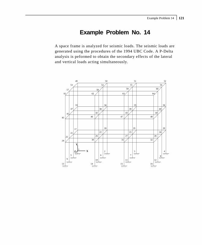
Example Problem 14 121
Example Problem No. 14
A space frame is analyzed for seismic loads. The seismic loads are generated using the procedures of the 1994 UBC Code. A P-Delta analysis is peformed to obtain the secondary effects of the lateral and vertical loads acting simultaneously.
13
9
5 6 7 8
10 11 12
14 15 16
17
4321
18 19 20
21 22 23 24
25 26 27 28
29 30 31 32
33 34 35 36
37 38 39 40
41 42 43 44
45 46 47 48
49 50 51 52
54 5553 56
57 58 59 60
61 62 63 64
X
Y
Z
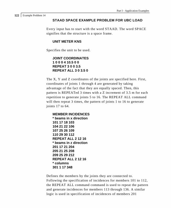
Part I - Application Examples Example Problem 14 122
STAAD SPACE EXAMPLE PROBLEM FOR UBC LOAD
Every input has to start with the word STAAD. The word SPACE signifies that the structure is a space frame.
UNIT METER KNS
Specifies the unit to be used. JOINT COORDINATES 1 0 0 0 4 10.5 0 0 REPEAT 3 0 0 3.5 REPEAT ALL 3 0 3.5 0
The X, Y and Z coordinates of the joints are specified here. First, coordinates of joints 1 through 4 are generated by taking advantage of the fact that they are equally spaced. Then, this pattern is REPEATed 3 times with a Z increment of 3.5 m for each repetition to generate joints 5 to 16. The REPEAT ALL command will then repeat 3 times, the pattern of joints 1 to 16 to generate joints 17 to 64.
MEMBER INCIDENCES * beams in x direction 101 17 18 103 104 21 22 106 107 25 26 109 110 29 30 112 REPEAT ALL 2 12 16 * beams in z direction 201 17 21 204 205 21 25 208 209 25 29 212 REPEAT ALL 2 12 16 * columns 301 1 17 348
Defines the members by the joints they are connected to. Following the specification of incidences for members 101 to 112, the REPEAT ALL command command is used to repeat the pattern and generate incidences for members 113 through 136. A similar logic is used in specification of incidences of members 201

Example Problem 14 123
through 212 and generation of incidences for members 213 to 236. Finally, members incidences of columns 301 to 348 are specified.
MEMBER PROPERTIES BRITISH 101 TO 136 201 TO 236 PRIS YD 0.40 ZD 0.30 301 TO 348 TA ST UB457X152X52
The beam members have prismatic member property specification (YD & ZD) while the columns (members 301 to 348) have their properties called from the built-in BRITISH steel table.
CONSTANT E STEEL MEMB 301 TO 348 E CONCRETE MEMB 101 TO 136 201 TO 236 DENSITY STEEL MEMB 301 TO 348 DENSITY CONCRETE MEMB 101 TO 136 201 TO 236 POISSON STEEL MEMB 301 TO 348 POISSON CONCRETE MEMB 101 TO 136 201 TO 236
In the specification of material constants, the default built-in values are used. The user may see these values with the help of the command PRINT MATERIAL PROPERTIES following the above commands.
SUPPORT 1 TO 16 FIXED
Indicates the joints where the supports are located as well as the type of support restraints.
DEFINE UBC LOAD ZONE 0.2 I 1.0 RWX 9 RWZ 9 S 1.5 CT 0.032 SELFWEIGHT JOINT WEIGHT 17 TO 48 WEIGHT 7.0 49 TO 64 WEIGHT 3.5
There are two stages in the command specification of the UBC loads. The first stage is initiated with the command DEFINE UBC LOAD. Here we specify parameters such as Zone factor, Importance factor, site coefficient for soil characteristics etc. and,

Part I - Application Examples Example Problem 14 124
LOAD 2
the vertical loads (weights) from which the base shear will be calculated. The vertical loads may be specified in the form of selfweight, joint weights and/or member weights. Member weights are not shown in this example. It is important to note that these vertical loads are used purely in the determination of the horizontal base shear only. In other words, the structure is not analysed for these vertical loads.
LOAD 1 UBC LOAD X 0.75 SELFWEIGHT Y -1.0 JOINT LOADS 17 TO 48 FY -7.0 49 TO 64 FY -3.5
This is the second stage in which the UBC load is applied with the help of a load case number, corresponding direction (X in the above case) and a factor by which the generated horizontal loads should be multiplied. Along with the UBC load, deadweight is also added to the same load case. Since we will be doing second-order (PDELTA) analysis, it is important that we include horizontal and vertical loads in the same load case.
UBC LOAD Z 0.75 SELFWEIGHT Y -1.0 JOINT LOADS 17 TO 48 FY –7.0 49 TO 64 FY –3.5
In load case 2, the UBC load is being applied in the Z direction. Vertical loads too are part of this case.
PDELTA ANALYSIS PRINT LOAD DATA We are requesting a second-order analysis by specifying the command PDELTA ANALYSIS. PRINT LOAD DATA is used to obtain a report of all the applied and generated loadings.

Example Problem 14 125
PRINT SUPPORT REACTIONS FINISH
The above commands are self-explanatory.

Part I - Application Examples Example Problem 14 126
**************************************************** * * * STAAD.Pro * * Version 2007 Build 02 * * Proprietary Program of * * Research Engineers, Intl. * * Date= * * Time= * * * * USER ID: * **************************************************** 1. STAAD SPACE EXAMPLE PROBLEM FOR UBC LOAD 2. UNIT METER KNS 3. JOINT COORDINATES 4. 1 0 0 0 4 10.5 0 0 5. REPEAT 3 0 0 3.5 6. REPEAT ALL 3 0 3.5 0 7. MEMBER INCIDENCES 8. * BEAMS IN X DIRECTION 9. 101 17 18 103 10. 104 21 22 106 11. 107 25 26 109 12. 110 29 30 112 13. REPEAT ALL 2 12 16 14. * BEAMS IN Z DIRECTION 15. 201 17 21 204 16. 205 21 25 208 17. 209 25 29 212 18. REPEAT ALL 2 12 16 19. * COLUMNS 20. 301 1 17 348 21. MEMBER PROPERTIES BRITISH 22. 101 TO 136 201 TO 236 PRIS YD 0.40 ZD 0.30 23. 301 TO 348 TA ST UB457X152X52 24. CONSTANT 25. E STEEL MEMB 301 TO 348 26. E CONCRETE MEMB 101 TO 136 201 TO 236 27. DENSITY STEEL MEMB 301 TO 348 28. DENSITY CONCRETE MEMB 101 TO 136 201 TO 236 29. POISSON STEEL MEMB 301 TO 348 30. POISSON CONCRETE MEMB 101 TO 136 201 TO 236 31. SUPPORT 32. 1 TO 16 FIXED 33. DEFINE UBC LOAD 34. ZONE 0.2 I 1.0 RWX 9 RWZ 9 S 1.5 CT 0.032 35. SELFWEIGHT 36. JOINT WEIGHT 37. 17 TO 48 WEIGHT 7.0 38. 49 TO 64 WEIGHT 3.5 39. LOAD 1 40. UBC LOAD X 0.75 41. SELFWEIGHT Y -1.0 42. JOINT LOADS 43. 17 TO 48 FY -7.0 44. 49 TO 64 FY -3.5 45. LOAD 2 46. UBC LOAD Z 0.75 47. SELFWEIGHT Y -1.0 48. JOINT LOADS 49. 17 TO 48 FY -7.0 50. 49 TO 64 FY -3.5 51. PDELTA ANALYSIS PRINT LOAD DATA P R O B L E M S T A T I S T I C S ----------------------------------- NUMBER OF JOINTS/MEMBER+ELEMENTS/SUPPORTS = 64/ 120/ 16 SOLVER USED IS THE IN-CORE ADVANCED SOLVER TOTAL PRIMARY LOAD CASES = 2, TOTAL DEGREES OF FREEDOM = 288

Example Problem 14 127
LOADING 1 ----------- SELFWEIGHT Y -1.000 ACTUAL WEIGHT OF THE STRUCTURE = 798.454 KNS JOINT LOAD - UNIT KNS METE JOINT FORCE-X FORCE-Y FORCE-Z MOM-X MOM-Y MOM-Z 17 0.00 -7.00 0.00 0.00 0.00 0.00 18 0.00 -7.00 0.00 0.00 0.00 0.00 19 0.00 -7.00 0.00 0.00 0.00 0.00 20 0.00 -7.00 0.00 0.00 0.00 0.00 21 0.00 -7.00 0.00 0.00 0.00 0.00 22 0.00 -7.00 0.00 0.00 0.00 0.00 23 0.00 -7.00 0.00 0.00 0.00 0.00 24 0.00 -7.00 0.00 0.00 0.00 0.00 25 0.00 -7.00 0.00 0.00 0.00 0.00 26 0.00 -7.00 0.00 0.00 0.00 0.00 27 0.00 -7.00 0.00 0.00 0.00 0.00 28 0.00 -7.00 0.00 0.00 0.00 0.00 29 0.00 -7.00 0.00 0.00 0.00 0.00 30 0.00 -7.00 0.00 0.00 0.00 0.00 31 0.00 -7.00 0.00 0.00 0.00 0.00 32 0.00 -7.00 0.00 0.00 0.00 0.00 33 0.00 -7.00 0.00 0.00 0.00 0.00 34 0.00 -7.00 0.00 0.00 0.00 0.00 35 0.00 -7.00 0.00 0.00 0.00 0.00 36 0.00 -7.00 0.00 0.00 0.00 0.00 37 0.00 -7.00 0.00 0.00 0.00 0.00 38 0.00 -7.00 0.00 0.00 0.00 0.00 39 0.00 -7.00 0.00 0.00 0.00 0.00 40 0.00 -7.00 0.00 0.00 0.00 0.00 41 0.00 -7.00 0.00 0.00 0.00 0.00 42 0.00 -7.00 0.00 0.00 0.00 0.00 43 0.00 -7.00 0.00 0.00 0.00 0.00 44 0.00 -7.00 0.00 0.00 0.00 0.00 45 0.00 -7.00 0.00 0.00 0.00 0.00 46 0.00 -7.00 0.00 0.00 0.00 0.00 47 0.00 -7.00 0.00 0.00 0.00 0.00 48 0.00 -7.00 0.00 0.00 0.00 0.00 49 0.00 -3.50 0.00 0.00 0.00 0.00 50 0.00 -3.50 0.00 0.00 0.00 0.00 51 0.00 -3.50 0.00 0.00 0.00 0.00 52 0.00 -3.50 0.00 0.00 0.00 0.00 53 0.00 -3.50 0.00 0.00 0.00 0.00 54 0.00 -3.50 0.00 0.00 0.00 0.00 55 0.00 -3.50 0.00 0.00 0.00 0.00 56 0.00 -3.50 0.00 0.00 0.00 0.00 57 0.00 -3.50 0.00 0.00 0.00 0.00 58 0.00 -3.50 0.00 0.00 0.00 0.00 59 0.00 -3.50 0.00 0.00 0.00 0.00 60 0.00 -3.50 0.00 0.00 0.00 0.00 61 0.00 -3.50 0.00 0.00 0.00 0.00 62 0.00 -3.50 0.00 0.00 0.00 0.00 63 0.00 -3.50 0.00 0.00 0.00 0.00 64 0.00 -3.50 0.00 0.00 0.00 0.00

Part I - Application Examples Example Problem 14 128
LOADING 2 ----------- SELFWEIGHT Y -1.000 ACTUAL WEIGHT OF THE STRUCTURE = 798.454 KNS JOINT LOAD - UNIT KNS METE JOINT FORCE-X FORCE-Y FORCE-Z MOM-X MOM-Y MOM-Z 17 0.00 -7.00 0.00 0.00 0.00 0.00 18 0.00 -7.00 0.00 0.00 0.00 0.00 19 0.00 -7.00 0.00 0.00 0.00 0.00 20 0.00 -7.00 0.00 0.00 0.00 0.00 21 0.00 -7.00 0.00 0.00 0.00 0.00 22 0.00 -7.00 0.00 0.00 0.00 0.00 23 0.00 -7.00 0.00 0.00 0.00 0.00 24 0.00 -7.00 0.00 0.00 0.00 0.00 25 0.00 -7.00 0.00 0.00 0.00 0.00 26 0.00 -7.00 0.00 0.00 0.00 0.00 27 0.00 -7.00 0.00 0.00 0.00 0.00 28 0.00 -7.00 0.00 0.00 0.00 0.00 29 0.00 -7.00 0.00 0.00 0.00 0.00 30 0.00 -7.00 0.00 0.00 0.00 0.00 31 0.00 -7.00 0.00 0.00 0.00 0.00 32 0.00 -7.00 0.00 0.00 0.00 0.00 33 0.00 -7.00 0.00 0.00 0.00 0.00 34 0.00 -7.00 0.00 0.00 0.00 0.00 35 0.00 -7.00 0.00 0.00 0.00 0.00 36 0.00 -7.00 0.00 0.00 0.00 0.00 37 0.00 -7.00 0.00 0.00 0.00 0.00 38 0.00 -7.00 0.00 0.00 0.00 0.00 39 0.00 -7.00 0.00 0.00 0.00 0.00 40 0.00 -7.00 0.00 0.00 0.00 0.00 41 0.00 -7.00 0.00 0.00 0.00 0.00 42 0.00 -7.00 0.00 0.00 0.00 0.00 43 0.00 -7.00 0.00 0.00 0.00 0.00 44 0.00 -7.00 0.00 0.00 0.00 0.00 45 0.00 -7.00 0.00 0.00 0.00 0.00 46 0.00 -7.00 0.00 0.00 0.00 0.00 47 0.00 -7.00 0.00 0.00 0.00 0.00 48 0.00 -7.00 0.00 0.00 0.00 0.00 49 0.00 -3.50 0.00 0.00 0.00 0.00 50 0.00 -3.50 0.00 0.00 0.00 0.00 51 0.00 -3.50 0.00 0.00 0.00 0.00 52 0.00 -3.50 0.00 0.00 0.00 0.00 53 0.00 -3.50 0.00 0.00 0.00 0.00 54 0.00 -3.50 0.00 0.00 0.00 0.00 55 0.00 -3.50 0.00 0.00 0.00 0.00 56 0.00 -3.50 0.00 0.00 0.00 0.00 57 0.00 -3.50 0.00 0.00 0.00 0.00 58 0.00 -3.50 0.00 0.00 0.00 0.00 59 0.00 -3.50 0.00 0.00 0.00 0.00 60 0.00 -3.50 0.00 0.00 0.00 0.00 61 0.00 -3.50 0.00 0.00 0.00 0.00 62 0.00 -3.50 0.00 0.00 0.00 0.00 63 0.00 -3.50 0.00 0.00 0.00 0.00 64 0.00 -3.50 0.00 0.00 0.00 0.00 **WARNING: IF THIS UBC/IBC ANALYSIS HAS TENSION/COMPRESSION OR REPEAT LOAD OR RE-ANALYSIS OR SELECT OPTIMIZE, THEN EACH UBC/IBC CASE SHOULD BE FOLLOWED BY PERFORM ANALYSIS & CHANGE. *********************************************************** * * * X DIRECTION : Ta = 0.455 Tb = 0.285 Tuser = 0.000 * * C = 2.7500, LOAD FACTOR = 0.750 * * UBC TYPE = 94 * * UBC FACTOR V = 0.0611 x 1078.46 = 65.91 KNS * * * ***********************************************************

Example Problem 14 129
*********************************************************** * * * Z DIRECTION : Ta = 0.455 Tb = 1.103 Tuser = 0.000 * * C = 2.7500, LOAD FACTOR = 0.750 * * UBC TYPE = 94 * * UBC FACTOR V = 0.0611 x 1078.46 = 65.91 KNS * * * *********************************************************** JOINT LATERAL TORSIONAL LOAD - 1 LOAD (KNS ) MOMENT (KNS -METE) FACTOR - 0.750 ----- ------- --------- 17 FX 0.449 MY 0.000 18 FX 0.568 MY 0.000 19 FX 0.568 MY 0.000 20 FX 0.449 MY 0.000 21 FX 0.568 MY 0.000 22 FX 0.687 MY 0.000 23 FX 0.687 MY 0.000 24 FX 0.568 MY 0.000 25 FX 0.568 MY 0.000 26 FX 0.687 MY 0.000 27 FX 0.687 MY 0.000 28 FX 0.568 MY 0.000 29 FX 0.449 MY 0.000 30 FX 0.568 MY 0.000 31 FX 0.568 MY 0.000 32 FX 0.449 MY 0.000 ----------- ----------- TOTAL = 9.083 0.000 AT LEVEL 3.500 METE 33 FX 0.898 MY 0.000 34 FX 1.135 MY 0.000 35 FX 1.135 MY 0.000 36 FX 0.898 MY 0.000 37 FX 1.135 MY 0.000 38 FX 1.373 MY 0.000 39 FX 1.373 MY 0.000 40 FX 1.135 MY 0.000 41 FX 1.135 MY 0.000 42 FX 1.373 MY 0.000 43 FX 1.373 MY 0.000 44 FX 1.135 MY 0.000 45 FX 0.898 MY 0.000 46 FX 1.135 MY 0.000 47 FX 1.135 MY 0.000 48 FX 0.898 MY 0.000 ----------- ----------- TOTAL = 18.166 0.000 AT LEVEL 7.000 METE 49 FX 1.030 MY 0.000 50 FX 1.386 MY 0.000 51 FX 1.386 MY 0.000 52 FX 1.030 MY 0.000 53 FX 1.386 MY 0.000 54 FX 1.743 MY 0.000 55 FX 1.743 MY 0.000 56 FX 1.386 MY 0.000 57 FX 1.386 MY 0.000 58 FX 1.743 MY 0.000 59 FX 1.743 MY 0.000 60 FX 1.386 MY 0.000 61 FX 1.030 MY 0.000 62 FX 1.386 MY 0.000 63 FX 1.386 MY 0.000 64 FX 1.030 MY 0.000 ----------- ----------- TOTAL = 22.181 0.000 AT LEVEL 10.500 METE

Part I - Application Examples Example Problem 14 130
JOINT LATERAL TORSIONAL LOAD - 2 LOAD (KNS ) MOMENT (KNS -METE) FACTOR - 0.750 ----- ------- --------- 17 FZ 0.449 MY 0.000 18 FZ 0.568 MY 0.000 19 FZ 0.568 MY 0.000 20 FZ 0.449 MY 0.000 21 FZ 0.568 MY 0.000 22 FZ 0.687 MY 0.000 23 FZ 0.687 MY 0.000 24 FZ 0.568 MY 0.000 25 FZ 0.568 MY 0.000 26 FZ 0.687 MY 0.000 27 FZ 0.687 MY 0.000 28 FZ 0.568 MY 0.000 29 FZ 0.449 MY 0.000 30 FZ 0.568 MY 0.000 31 FZ 0.568 MY 0.000 32 FZ 0.449 MY 0.000 ----------- ----------- TOTAL = 9.083 0.000 AT LEVEL 3.500 METE 33 FZ 0.898 MY 0.000 34 FZ 1.135 MY 0.000 35 FZ 1.135 MY 0.000 36 FZ 0.898 MY 0.000 37 FZ 1.135 MY 0.000 38 FZ 1.373 MY 0.000 39 FZ 1.373 MY 0.000 40 FZ 1.135 MY 0.000 41 FZ 1.135 MY 0.000 42 FZ 1.373 MY 0.000 43 FZ 1.373 MY 0.000 44 FZ 1.135 MY 0.000 45 FZ 0.898 MY 0.000 46 FZ 1.135 MY 0.000 47 FZ 1.135 MY 0.000 48 FZ 0.898 MY 0.000 ----------- ----------- TOTAL = 18.166 0.000 AT LEVEL 7.000 METE 49 FZ 1.030 MY 0.000 50 FZ 1.386 MY 0.000 51 FZ 1.386 MY 0.000 52 FZ 1.030 MY 0.000 53 FZ 1.386 MY 0.000 54 FZ 1.743 MY 0.000 55 FZ 1.743 MY 0.000 56 FZ 1.386 MY 0.000 57 FZ 1.386 MY 0.000 58 FZ 1.743 MY 0.000 59 FZ 1.743 MY 0.000 60 FZ 1.386 MY 0.000 61 FZ 1.030 MY 0.000 62 FZ 1.386 MY 0.000 63 FZ 1.386 MY 0.000 64 FZ 1.030 MY 0.000 ----------- ----------- TOTAL = 22.181 0.000 AT LEVEL 10.500 METE ************ END OF DATA FROM INTERNAL STORAGE ************ 52. PRINT SUPPORT REACTIONS

Example Problem 14 131
SUPPORT REACTIONS -UNIT KNS METE STRUCTURE TYPE = SPACE ----------------- JOINT LOAD FORCE-X FORCE-Y FORCE-Z MOM-X MOM-Y MOM Z 1 1 -2.22 43.36 0.06 0.07 0.00 5.75 2 0.45 41.43 -3.03 -5.61 0.00 -0.49 2 1 -3.40 65.55 0.06 0.07 0.00 7.02 2 0.01 56.12 -3.00 -5.62 0.00 -0.02 3 1 -3.42 64.35 0.06 0.07 0.00 7.06 2 -0.01 56.12 -3.00 -5.62 0.00 0.02 4 1 -3.12 57.12 0.06 0.07 0.00 6.73 2 -0.45 41.43 -3.03 -5.61 0.00 0.49 5 1 -2.31 62.76 -0.01 -0.01 0.00 5.96 2 0.45 73.81 -3.14 -5.82 0.00 -0.49 6 1 -3.51 85.18 -0.01 -0.01 0.00 7.26 2 0.01 88.52 -3.11 -5.83 0.00 -0.02 7 1 -3.53 83.95 -0.01 -0.01 0.00 7.29 2 -0.01 88.52 -3.11 -5.83 0.00 0.02 8 1 -3.21 76.95 -0.01 -0.01 0.00 6.94 2 -0.45 73.81 -3.14 -5.82 0.00 0.49 9 1 -2.31 62.76 0.01 0.01 0.00 5.96 2 0.45 65.90 -3.14 -5.80 0.00 -0.49 10 1 -3.51 85.18 0.01 0.01 0.00 7.26 2 0.01 80.60 -3.11 -5.81 0.00 -0.02 11 1 -3.53 83.95 0.01 0.01 0.00 7.29 2 -0.01 80.60 -3.11 -5.81 0.00 0.02 12 1 -3.21 76.95 0.01 0.01 0.00 6.94 2 -0.45 65.90 -3.14 -5.80 0.00 0.49 13 1 -2.22 43.36 -0.06 -0.07 0.00 5.75 2 0.45 59.06 -3.11 -5.75 0.00 -0.49 14 1 -3.40 65.55 -0.06 -0.07 0.00 7.02 2 0.01 73.79 -3.08 -5.76 0.00 -0.02 15 1 -3.42 64.35 -0.06 -0.07 0.00 7.06 2 -0.01 73.79 -3.08 -5.76 0.00 0.02 16 1 -3.12 57.12 -0.06 -0.07 0.00 6.73 2 -0.45 59.06 -3.11 -5.75 0.00 0.49 ************** END OF LATEST ANALYSIS RESULT ************** 53. FINISH *********** END OF THE STAAD.Pro RUN *********** **** DATE= TIME= **** ************************************************************ * For questions on STAAD.Pro, please contact * * Research Engineers Offices at the following locations * * * * Telephone Email * * USA: +1 (714)974-2500 [email protected] * * CANADA +1 (905)632-4771 [email protected] * * UK +44(1454)207-000 [email protected] * * FRANCE +33(0)1 64551084 [email protected] * * GERMANY +49/931/40468-71 [email protected] * * NORWAY +47 67 57 21 30 [email protected] * * SINGAPORE +65 6225-6158 [email protected] * * INDIA +91(033)4006-2021 [email protected] * * JAPAN +81(03)5952-6500 [email protected] * * CHINA +86(411)363-1983 [email protected] * * THAILAND +66(0)2645-1018/19 [email protected] * * * * North America [email protected] * * Europe [email protected] * * Asia [email protected] * ************************************************************

Part I - Application Examples Example Problem 14 132
NOTES

Example Problem 15 133
Example Problem No. 15
A space frame is analyzed for loads generated using the built-in wind and floor load generation facilities.
1 2 3
4 5
6 7 8
9 10 11
12 13
14 15 16
17 18 19
20 21
22 23 24
1 23
4 5
6 7 8
9 10 11
12 13
14 15
16
17 18
19
20 21
22 23
24
25 26
27
28
29
3031
32
33 35
34
X
Y
Z

Part I - Application Examples
Example Problem 15 134
STAAD SPACE - WIND AND FLOOR LOAD GENERATION
This is a SPACE frame analysis problem. Every STAAD input has to start with the command STAAD. The SPACE specification is used to denote a SPACE frame.
UNIT METER KNS
The UNIT specification is used to specify the length and/or force units to be used.
JOINT COORDINATES 1 0 0 0 2 4 0 0 3 9 0 0 4 0 0 4 5 4 0 4 6 0 0 8 7 4 0 8 8 9 0 8 REPEAT ALL 2 0 3.5 0
The JOINT COORDINATE specification is used to specify the X, Y and Z coordinates of the JOINTs. Note that the REPEAT ALL command has been used to generate JOINTs for the two upper storeys each with a Y increment of 3.5 m.
MEMBER INCIDENCES * Columns 1 1 9 16 * Beams in the X direction 17 9 10 18 19 12 13 20 14 15 21 22 17 18 23 24 20 21 25 22 23 26 * Beams in the Z direction 27 9 12 ; 28 12 14 ; 29 10 13 ; 30 13 15 ; 31 11 16 32 17 20 ; 33 20 22 ; 34 18 21 ; 35 21 23 ; 36 19 24

Example Problem 15 135
The MEMBER INCIDENCE specification is used for specifying MEMBER connectivities.
MEMBER PROPERTIES BRITISH 1 TO 16 TA ST UB457X191X74 17 TO 26 TA ST UB457X152X52 27 TO 36 TA ST UB457X152X52
Properties for all members are specified from the built-in BRITISH steel table. Three different sections have been used.
CONSTANT E STEEL ALL DENSITY STEEL ALL POISSON STEEL ALL
The CONSTANT specification is used to specify material properties. In this case, the built-in default values have been used.
SUPPORT 1 TO 8 FIXED BUT MX MZ
The SUPPORTs of the structure are defined through the SUPPORT specification. Here all the supports are FIXED with RELEASES specified in the MX (rotation about global X-axis) and MZ (rotation about global Z-axis) directions.
DEFINE WIND LOAD TYPE 1 INTENSITY 1.0 1.5 HEIGHT 3.5 7.0 EXPOSURE 0.90 YRANGE 6.0 8.0 EXPOSURE 0.85 JOINT 9 12 14
When a structure has to be analysed for wind loading, the engineer is confronted with the task of first converting an abstract quantity like wind velocity or wind pressure into concentrated loads at joints, distributed loads on members, or pressure loads on plates. The large number of calculations involved in this conversion can be avoided by making use of STAAD’s wind load generation utility. This utility takes wind pressure at various heights as the input, and converts them to values that can then be used as

Part I - Application Examples
Example Problem 15 136
concentrated forces known as joint loads in specific load cases. The input specification is done in two stages. The first stage is initiated above through the DEFINE WIND LOAD command. The basic parameters of the WIND loading are specified here. All values need to be provided in the current UNIT system. Each wind category is identified with a TYPE number (an identification mark) which is used later to specify load cases.
In this example, two different wind intensities (1.0 KN/sq. m and 1.5 KN/sq. m) are specified for two different height zones (0 to 3.5m and 3.5 to 7.0m). The EXPOSURE specification is used to mitigate or magnify the effect at specific nodes due to special considerations like openings in the structure. In this case, two different exposure factors are specified. The first EXPOSURE specification specifies the exposure factor as 0.9 for all joints within the height range (defined as global Y-range) of 6.0m – 8.0m. The second EXPOSURE specification specifies the exposure factor as 0.85 for joints 9, 12 and 14. In the EXPOSURE factor specification, the joints may be specified directly or through a vertical range specification.
LOAD 1 WIND LOAD IN X-DIRECTION WIND LOAD X 1.2 TYPE 1
This is the second stage of input specification for the wind load generation. The term WIND LOAD and the direction term that follows are used to specify the WIND LOADING in a particular lateral direction. In this case, WIND loading TYPE 1, defined previously, is being applied in the global X-direction with a positive multiplication factor of 1.2 .
LOAD 2 FLOOR LOAD @ Y = 3.5M AND 7M FLOOR LOAD YRANGE 3.4 3.6 FLOAD –5.0 XRANGE 0.0 4.0 ZRANGE 0.0 8.0 YRANGE 3.4 3.6 FLOAD –2.5 XRANGE 4.0 9.0 ZRANGE 0.0 8.0 YRANGE 6.9 7.1 FLOAD –2.5
In load case 2 in this problem, a floor load generation is performed. In a floor load generation, a pressure load (force per unit area) is converted by the program into specific points forces

Example Problem 15 137
and distributed forces on the members located in that region. The YRANGE, XRANGE and ZRANGE specifications are used to define the area of the structure on which the pressure is acting. The FLOAD specification is used to specify the value of that pressure. All values need to be provided in the current UNIT system. For example, in the first line in the above FLOOR LOAD specification, the region is defined as being located within the bounds YRANGE of 3.4 – 3.6 m, XRANGE of 0.0 - 4.0 m and ZRANGE of 0.0 - 8.0 m. The –5.0 signifies that the pressure is 5.0 KN/sq.m. in the negative global Y direction. The program will identify the members lying within the specified region and derive MEMBER LOADS on these members based on two-way load distribution.
PERFORM ANALYSIS PRINT LOAD DATA
We can view the values and position of the generated loads with the help of the PRINT LOAD DATA command used above along with the PERFORM ANALYSIS command.
PRINT SUPPORT REACTION FINISH
Above commands are self-explanatory.

Part I - Application Examples
Example Problem 15 138
**************************************************** * * * STAAD.Pro * * Version 2007 Build 02 * * Proprietary Program of * * Research Engineers, Intl. * * Date= * * Time= * * * * USER ID: * **************************************************** 1. STAAD SPACE - WIND AND FLOOR LOAD GENERATION 2. UNIT METER KNS 3. JOINT COORDINATES 4. 1 0 0 0 5. 2 4 0 0 6. 3 9 0 0 7. 4 0 0 4 8. 5 4 0 4 9. 6 0 0 8 10. 7 4 0 8 11. 8 9 0 8 12. REPEAT ALL 2 0 3.5 0 13. MEMBER INCIDENCES 14. * COLUMNS 15. 1 1 9 16 16. * BEAMS IN THE X DIRECTION 17. 17 9 10 18 18. 19 12 13 19. 20 14 15 21 20. 22 17 18 23 21. 24 20 21 22. 25 22 23 26 23. * BEAMS IN THE Z DIRECTION 24. 27 9 12 ; 28 12 14 ; 29 10 13 ; 30 13 15 ; 31 11 16 25. 32 17 20 ; 33 20 22 ; 34 18 21 ; 35 21 23 ; 36 19 24 26. MEMBER PROPERTIES BRITISH 27. 1 TO 16 TA ST UB457X191X74 28. 17 TO 26 TA ST UB457X152X52 29. 27 TO 36 TA ST UB457X152X52 30. CONSTANT 31. E STEEL ALL 32. DENSITY STEEL ALL 33. POISSON STEEL ALL 34. SUPPORT 35. 1 TO 8 FIXED BUT MX MZ 36. DEFINE WIND LOAD 37. TYPE 1 38. INTENSITY 1.0 1.5 HEIGHT 3.5 7.0 39. EXPOSURE 0.90 YRANGE 6.0 8.0 40. EXPOSURE 0.85 JOINT 9 12 14 41. LOAD 1 WIND LOAD IN X-DIRECTION 42. WIND LOAD X 1.2 TYPE 1 43. LOAD 2 FLOOR LOAD @ Y = 3.5M AND 7M 44. FLOOR LOAD 45. YRANGE 3.4 3.6 FLOAD -5.0 XRANGE 0.0 4.0 ZRANGE 0.0 8.0 **WARNING** about Floor/OneWay Loads/Weights. Please note that depending on the shape of the floor you may have to break up the FLOOR/ONEWAY LOAD into multiple commands. For details please refer to Technical Reference Manual Section 5.32.4 Note 6. 46. YRANGE 3.4 3.6 FLOAD -2.5 XRANGE 4.0 9.0 ZRANGE 0.0 8.0 47. YRANGE 6.9 7.1 FLOAD -2.5 48. PERFORM ANALYSIS PRINT LOAD DATA

Example Problem 15 139
P R O B L E M S T A T I S T I C S ----------------------------------- NUMBER OF JOINTS/MEMBER+ELEMENTS/SUPPORTS = 24/ 36/ 8 SOLVER USED IS THE IN-CORE ADVANCED SOLVER TOTAL PRIMARY LOAD CASES = 2, TOTAL DEGREES OF FREEDOM = 112 LOADING 1 WIND LOAD IN X-DIRECTION ----------- JOINT LOAD - UNIT KNS METE JOINT FORCE-X FORCE-Y FORCE-Z MOM-X MOM-Y MOM-Z 1 4.20 0.00 0.00 0.00 0.00 0.00 4 8.40 0.00 0.00 0.00 0.00 0.00 6 4.20 0.00 0.00 0.00 0.00 0.00 9 8.93 0.00 0.00 0.00 0.00 0.00 12 17.85 0.00 0.00 0.00 0.00 0.00 14 8.93 0.00 0.00 0.00 0.00 0.00 17 5.67 0.00 0.00 0.00 0.00 0.00 20 11.34 0.00 0.00 0.00 0.00 0.00 22 5.67 0.00 0.00 0.00 0.00 0.00 LOADING 2 FLOOR LOAD @ Y = 3.5M AND 7M ----------- MEMBER LOAD - UNIT KNS METE MEMBER UDL L1 L2 CON L LIN1 LIN2 17 -0.1563 GY 0.17 17 -0.4688 GY 0.39 17 -0.7812 GY 0.63 17 -1.0938 GY 0.88 17 -1.4062 GY 1.13 17 -1.7188 GY 1.38 17 -2.0312 GY 1.63 17 -2.3438 GY 1.88 17 -2.3438 GY 2.12 17 -2.0312 GY 2.37 17 -1.7188 GY 2.62 17 -1.4062 GY 2.87 17 -1.0938 GY 3.12 17 -0.7812 GY 3.37 17 -0.4688 GY 3.61 17 -0.1563 GY 3.83 29 -0.1563 GY 0.17 29 -0.4688 GY 0.39 29 -0.7812 GY 0.63 29 -1.0938 GY 0.88 29 -1.4062 GY 1.13 29 -1.7188 GY 1.38 29 -2.0312 GY 1.63 29 -2.3438 GY 1.88 29 -2.3438 GY 2.12 29 -2.0312 GY 2.37 29 -1.7188 GY 2.62 29 -1.4062 GY 2.87 29 -1.0938 GY 3.12 29 -0.7812 GY 3.37 29 -0.4688 GY 3.61 29 -0.1563 GY 3.83 19 -0.1563 GY 0.17 19 -0.4688 GY 0.39 19 -0.7812 GY 0.63 19 -1.0938 GY 0.88 19 -1.4062 GY 1.13 19 -1.7188 GY 1.38 19 -2.0312 GY 1.63

Part I - Application Examples
Example Problem 15 140
20 -1.4062 GY 2.87
MEMBER LOAD - UNIT KNS METE MEMBER UDL L1 L2 CON L LIN1 LIN2 19 -2.3438 GY 1.88 19 -2.3438 GY 2.12 19 -2.0312 GY 2.37 19 -1.7188 GY 2.62 19 -1.4062 GY 2.87 19 -1.0938 GY 3.12 19 -0.7812 GY 3.37 19 -0.4688 GY 3.61 19 -0.1563 GY 3.83 27 -0.1563 GY 0.17 27 -0.4688 GY 0.39 27 -0.7812 GY 0.63 27 -1.0938 GY 0.88 27 -1.4062 GY 1.13 27 -1.7188 GY 1.38 27 -2.0312 GY 1.63 27 -2.3438 GY 1.88 27 -2.3438 GY 2.12 27 -2.0312 GY 2.37 27 -1.7188 GY 2.62 27 -1.4062 GY 2.87 27 -1.0938 GY 3.12 27 -0.7812 GY 3.37 27 -0.4688 GY 3.61 27 -0.1563 GY 3.83 19 -0.1563 GY 0.17 19 -0.4688 GY 0.39 19 -0.7812 GY 0.63 19 -1.0938 GY 0.88 19 -1.4062 GY 1.13 19 -1.7188 GY 1.38 19 -2.0312 GY 1.63 19 -2.3438 GY 1.88 19 -2.3438 GY 2.12 19 -2.0312 GY 2.37 19 -1.7188 GY 2.62 19 -1.4062 GY 2.87 19 -1.0938 GY 3.12 19 -0.7812 GY 3.37 19 -0.4688 GY 3.61 19 -0.1563 GY 3.83 30 -0.1563 GY 0.17 30 -0.4688 GY 0.39 30 -0.7812 GY 0.63 30 -1.0938 GY 0.88 30 -1.4062 GY 1.13 30 -1.7188 GY 1.38 30 -2.0312 GY 1.63 30 -2.3438 GY 1.88 30 -2.3438 GY 2.12 30 -2.0312 GY 2.37 30 -1.7188 GY 2.62 30 -1.4062 GY 2.87 30 -1.0938 GY 3.12 30 -0.7812 GY 3.37 30 -0.4688 GY 3.61 30 -0.1563 GY 3.83 20 -0.1563 GY 0.17 20 -0.4688 GY 0.39 20 -0.7812 GY 0.63 20 -1.0938 GY 0.88 20 -1.4062 GY 1.13 20 -1.7188 GY 1.38 20 -2.0312 GY 1.63 20 -2.3438 GY 1.88 20 -2.3438 GY 2.12 20 -2.0312 GY 2.37 20 -1.7188 GY 2.62

Example Problem 15 141
MEMBER LOAD - UNIT KNS METE MEMBER UDL L1 L2 CON L LIN1 LIN2 20 -1.0938 GY 3.12 20 -0.7812 GY 3.37 20 -0.4688 GY 3.61 20 -0.1563 GY 3.83 28 -0.1563 GY 0.17 28 -0.4688 GY 0.39 28 -0.7812 GY 0.63 28 -1.0938 GY 0.88 28 -1.4062 GY 1.13 28 -1.7188 GY 1.38 28 -2.0312 GY 1.63 28 -2.3438 GY 1.88 28 -2.3438 GY 2.12 28 -2.0312 GY 2.37 28 -1.7188 GY 2.62 28 -1.4062 GY 2.87 28 -1.0938 GY 3.12 28 -0.7812 GY 3.37 28 -0.4688 GY 3.61 28 -0.1563 GY 3.83 18 -0.1221 GY 0.21 18 -0.3662 GY 0.49 18 -0.6104 GY 0.79 18 -0.8545 GY 1.10 18 -1.0986 GY 1.41 18 -1.3428 GY 1.72 18 -1.5869 GY 2.04 18 -1.8311 GY 2.35 18 -1.8311 GY 2.65 18 -1.5869 GY 2.96 18 -1.3428 GY 3.28 18 -1.0986 GY 3.59 18 -0.8545 GY 3.90 18 -0.6104 GY 4.21 18 -0.3662 GY 4.51 18 -0.1221 GY 4.79 31 -0.1221 GY 0.21 31 -0.3662 GY 0.49 31 -0.6104 GY 0.79 31 -0.8545 GY 1.10 31 -1.0986 GY 1.41 31 -1.3428 GY 1.72 31 -1.5869 GY 2.04 31 -1.8311 GY 2.35 31 -6.2500 GY 2.50 5.50 31 -1.8311 GY 5.65 31 -1.5869 GY 5.96 31 -1.3428 GY 6.28 31 -1.0986 GY 6.59 31 -0.8545 GY 6.90 31 -0.6104 GY 7.21 31 -0.3662 GY 7.51 31 -0.1221 GY 7.79 21 -0.1221 GY 0.21 21 -0.3662 GY 0.49 21 -0.6104 GY 0.79 21 -0.8545 GY 1.10 21 -1.0986 GY 1.41 21 -1.3428 GY 1.72 21 -1.5869 GY 2.04 21 -1.8311 GY 2.35 21 -1.8311 GY 2.65 21 -1.5869 GY 2.96 21 -1.3428 GY 3.28 21 -1.0986 GY 3.59 21 -0.8545 GY 3.90 21 -0.6104 GY 4.21 21 -0.3662 GY 4.51 21 -0.1221 GY 4.79

Part I - Application Examples
Example Problem 15 142
MEMBER LOAD - UNIT KNS METE MEMBER UDL L1 L2 CON L LIN1 LIN2 30 -1.8311 GY 1.65 30 -1.5869 GY 1.96 30 -1.3428 GY 2.28 30 -1.0986 GY 2.59 30 -0.8545 GY 2.90 30 -0.6104 GY 3.21 30 -0.3662 GY 3.51 30 -0.1221 GY 3.79 30 -6.2500 GY 0.00 1.50 29 -0.1221 GY 0.21 29 -0.3662 GY 0.49 29 -0.6104 GY 0.79 29 -0.8545 GY 1.10 29 -1.0986 GY 1.41 29 -1.3428 GY 1.72 29 -1.5869 GY 2.04 29 -1.8311 GY 2.35 29 -6.2500 GY 2.50 4.00 22 -0.0781 GY 0.17 22 -0.2344 GY 0.39 22 -0.3906 GY 0.63 22 -0.5469 GY 0.88 22 -0.7031 GY 1.13 22 -0.8594 GY 1.38 22 -1.0156 GY 1.63 22 -1.1719 GY 1.88 22 -1.1719 GY 2.12 22 -1.0156 GY 2.37 22 -0.8594 GY 2.62 22 -0.7031 GY 2.87 22 -0.5469 GY 3.12 22 -0.3906 GY 3.37 22 -0.2344 GY 3.61 22 -0.0781 GY 3.83 34 -0.0781 GY 0.17 34 -0.2344 GY 0.39 34 -0.3906 GY 0.63 34 -0.5469 GY 0.88 34 -0.7031 GY 1.13 34 -0.8594 GY 1.38 34 -1.0156 GY 1.63 34 -1.1719 GY 1.88 34 -1.1719 GY 2.12 34 -1.0156 GY 2.37 34 -0.8594 GY 2.62 34 -0.7031 GY 2.87 34 -0.5469 GY 3.12 34 -0.3906 GY 3.37 34 -0.2344 GY 3.61 34 -0.0781 GY 3.83 24 -0.0781 GY 0.17 24 -0.2344 GY 0.39 24 -0.3906 GY 0.63 24 -0.5469 GY 0.88 24 -0.7031 GY 1.13 24 -0.8594 GY 1.38 24 -1.0156 GY 1.63 24 -1.1719 GY 1.88 24 -1.1719 GY 2.12 24 -1.0156 GY 2.37 24 -0.8594 GY 2.62 24 -0.7031 GY 2.87 24 -0.5469 GY 3.12 24 -0.3906 GY 3.37 24 -0.2344 GY 3.61 24 -0.0781 GY 3.83 32 -0.0781 GY 0.17 32 -0.2344 GY 0.39 32 -0.3906 GY 0.63

Example Problem 15 143
MEMBER LOAD - UNIT KNS METE MEMBER UDL L1 L2 CON L LIN1 LIN2 32 -0.5469 GY 0.88 32 -0.7031 GY 1.13 32 -0.8594 GY 1.38 32 -1.0156 GY 1.63 32 -1.1719 GY 1.88 32 -1.1719 GY 2.12 32 -1.0156 GY 2.37 32 -0.8594 GY 2.62 32 -0.7031 GY 2.87 32 -0.5469 GY 3.12 32 -0.3906 GY 3.37 32 -0.2344 GY 3.61 32 -0.0781 GY 3.83 23 -0.1221 GY 0.21 23 -0.3662 GY 0.49 23 -0.6104 GY 0.79 23 -0.8545 GY 1.10 23 -1.0986 GY 1.41 23 -1.3428 GY 1.72 23 -1.5869 GY 2.04 23 -1.8311 GY 2.35 23 -1.8311 GY 2.65 23 -1.5869 GY 2.96 23 -1.3428 GY 3.28 23 -1.0986 GY 3.59 23 -0.8545 GY 3.90 23 -0.6104 GY 4.21 23 -0.3662 GY 4.51 23 -0.1221 GY 4.79 36 -0.1221 GY 0.21 36 -0.3662 GY 0.49 36 -0.6104 GY 0.79 36 -0.8545 GY 1.10 36 -1.0986 GY 1.41 36 -1.3428 GY 1.72 36 -1.5869 GY 2.04 36 -1.8311 GY 2.35 36 -6.2500 GY 2.50 5.50 36 -1.8311 GY 5.65 36 -1.5869 GY 5.96 36 -1.3428 GY 6.28 36 -1.0986 GY 6.59 36 -0.8545 GY 6.90 36 -0.6104 GY 7.21 36 -0.3662 GY 7.51 36 -0.1221 GY 7.79 26 -0.1221 GY 0.21 26 -0.3662 GY 0.49 26 -0.6104 GY 0.79 26 -0.8545 GY 1.10 26 -1.0986 GY 1.41 26 -1.3428 GY 1.72 26 -1.5869 GY 2.04 26 -1.8311 GY 2.35 26 -1.8311 GY 2.65 26 -1.5869 GY 2.96 26 -1.3428 GY 3.28 26 -1.0986 GY 3.59 26 -0.8545 GY 3.90 26 -0.6104 GY 4.21 26 -0.3662 GY 4.51 26 -0.1221 GY 4.79 35 -1.8311 GY 1.65 35 -1.5869 GY 1.96 35 -1.3428 GY 2.28 35 -1.0986 GY 2.59 35 -0.8545 GY 2.90 35 -0.6104 GY 3.21 35 -0.3662 GY 3.51

Part I - Application Examples
Example Problem 15 144
MEMBER LOAD - UNIT KNS METE MEMBER UDL L1 L2 CON L LIN1 LIN2 35 -0.1221 GY 3.79 35 -6.2500 GY 0.00 1.50 34 -0.1221 GY 0.21 34 -0.3662 GY 0.49 34 -0.6104 GY 0.79 34 -0.8545 GY 1.10 34 -1.0986 GY 1.41 34 -1.3428 GY 1.72 34 -1.5869 GY 2.04 34 -1.8311 GY 2.35 34 -6.2500 GY 2.50 4.00 24 -0.0781 GY 0.17 24 -0.2344 GY 0.39 24 -0.3906 GY 0.63 24 -0.5469 GY 0.88 24 -0.7031 GY 1.13 24 -0.8594 GY 1.38 24 -1.0156 GY 1.63 24 -1.1719 GY 1.88 24 -1.1719 GY 2.12 24 -1.0156 GY 2.37 24 -0.8594 GY 2.62 24 -0.7031 GY 2.87 24 -0.5469 GY 3.12 24 -0.3906 GY 3.37 24 -0.2344 GY 3.61 24 -0.0781 GY 3.83 35 -0.0781 GY 0.17 35 -0.2344 GY 0.39 35 -0.3906 GY 0.63 35 -0.5469 GY 0.88 35 -0.7031 GY 1.13 35 -0.8594 GY 1.38 35 -1.0156 GY 1.63 35 -1.1719 GY 1.88 35 -1.1719 GY 2.12 35 -1.0156 GY 2.37 35 -0.8594 GY 2.62 35 -0.7031 GY 2.87 35 -0.5469 GY 3.12 35 -0.3906 GY 3.37 35 -0.2344 GY 3.61 35 -0.0781 GY 3.83 25 -0.0781 GY 0.17 25 -0.2344 GY 0.39 25 -0.3906 GY 0.63 25 -0.5469 GY 0.88 25 -0.7031 GY 1.13 25 -0.8594 GY 1.38 25 -1.0156 GY 1.63 25 -1.1719 GY 1.88 25 -1.1719 GY 2.12 25 -1.0156 GY 2.37 25 -0.8594 GY 2.62 25 -0.7031 GY 2.87 25 -0.5469 GY 3.12 25 -0.3906 GY 3.37 25 -0.2344 GY 3.61 25 -0.0781 GY 3.83 33 -0.0781 GY 0.17 33 -0.2344 GY 0.39 33 -0.3906 GY 0.63 33 -0.5469 GY 0.88 33 -0.7031 GY 1.13 33 -0.8594 GY 1.38 33 -1.0156 GY 1.63 33 -1.1719 GY 1.88 33 -1.1719 GY 2.12 33 -1.0156 GY 2.37

Example Problem 15 145
MEMBER LOAD - UNIT KNS METE MEMBER UDL L1 L2 CON L LIN1 LIN2 33 -0.8594 GY 2.62 33 -0.7031 GY 2.87 33 -0.5469 GY 3.12 33 -0.3906 GY 3.37 33 -0.2344 GY 3.61 33 -0.0781 GY 3.83 ************ END OF DATA FROM INTERNAL STORAGE ************ 49. PRINT SUPPORT REACTION SUPPORT REACTIONS -UNIT KNS METE STRUCTURE TYPE = SPACE ----------------- JOINT LOAD FORCE-X FORCE-Y FORCE-Z MOM-X MOM-Y MOM Z 1 1 -9.58 -11.46 -0.01 0.00 -0.01 0.00 2 0.80 25.70 0.16 0.00 0.00 0.00 2 1 -6.70 3.60 0.01 0.00 0.00 0.00 2 -0.15 52.75 0.26 0.00 0.00 0.00 3 1 -5.01 7.95 0.00 0.00 0.00 0.00 2 -0.71 49.30 1.16 0.00 0.00 0.00 4 1 -20.54 -28.14 0.00 0.00 0.00 0.00 2 1.72 66.85 0.00 0.00 0.00 0.00 5 1 -12.05 27.97 0.00 0.00 0.00 0.00 2 -1.61 117.68 0.00 0.00 0.00 0.00 6 1 -9.58 -11.46 0.01 0.00 0.01 0.00 2 0.80 25.70 -0.16 0.00 0.00 0.00 7 1 -6.70 3.60 -0.01 0.00 0.00 0.00 2 -0.15 52.75 -0.26 0.00 0.00 0.00 8 1 -5.01 7.95 0.00 0.00 0.00 0.00 2 -0.71 49.30 -1.16 0.00 0.00 0.00 ************** END OF LATEST ANALYSIS RESULT ************** 50. FINISH *********** END OF THE STAAD.Pro RUN *********** **** DATE= TIME= **** ************************************************************ * For questions on STAAD.Pro, please contact * * Research Engineers Offices at the following locations * * * * Telephone Email * * USA: +1 (714)974-2500 [email protected] * * CANADA +1 (905)632-4771 [email protected] * * UK +44(1454)207-000 [email protected] * * FRANCE +33(0)1 64551084 [email protected] * * GERMANY +49/931/40468-71 [email protected] * * NORWAY +47 67 57 21 30 [email protected] * * SINGAPORE +65 6225-6158 [email protected] * * INDIA +91(033)4006-2021 [email protected] * * JAPAN +81(03)5952-6500 [email protected] * * CHINA +86(411)363-1983 [email protected] * * THAILAND +66(0)2645-1018/19 [email protected] * * * * North America [email protected] * * Europe [email protected] * * Asia [email protected] * ************************************************************

Part I - Application Examples
Example Problem 15 146
NOTES

Example Problem 16 147
Example Problem No. 16
Dynamic Analysis (Time History) is performed for a 3 span beam with concentrated and distributed masses. The structure is subjected to “forcing function” and “ground motion” loading. The maxima of joint displacements, member end forces and support reactions are determined.

Part I - Application Examples Example Problem 16 148
STAAD PLANE EXAMPLE FOR TIME HISTORY ANALYSIS
Every input file has to start with the word STAAD. The word PLANE signifies that the structure is a plane frame.
UNITS CMS KNS
Specifies the units to be used. JOINT COORDINATES 1 0.0 0.0 0.0 2 0.0 120.0 0.0 3 0.0 240.0 0.0 4 0.0 360.0 0.0
Joint number followed by the X, Y and Z coordinates are specified above.
MEMBER INCIDENCES 1 1 2 3
Incidences of members 1 to 3 are specified above. MEMBER PROPERTIES 1 2 3 PRIS AX 100.0 IZ 833.33
All the members have "PRISMATIC" property specification. Since this is a PLANE frame, Area of cross section "AX", and Moment of Inertia "IZ" about the Z axis are adequate for the analysis.
SUPPORTS 1 4 PINNED
Pinned supports are located at nodes 1 and 4. CONSTANTS E 2850 ALL DENSITY 25E-6 ALL POISSON CONCRETE ALL
The material constants defined include Young's Modulus "E", density and Poisson’s ratio.

Example Problem 16 149
UNIT NEWTON METER DEFINE TIME HISTORY TYPE 1 FORCE 0.0 –20.0 0.5 100.0 1.0 200.0 1.5 500.0 2.0 800.0 2.5 500.0 3.0 70.0 TYPE 2 ACCELERATION 0.0 0.1 0.5 –0.25 1.0 –0.5 1.5 –0.9 2.0 –1.3 2.5 –1.0 3.0 –0.7 ARRIVAL TIMES 0.0 DAMPING 0.075 There are 2 stages in the command specification required for a time history analysis. The first stage is defined above. First the characteristics of the time varying load are provided. The loading type may be a forcing function (vibrating machinery) or ground motion (earthquake). The former is input in the form of time-force pairs while the latter is in the form of time-acceleration pairs. Following this data, all possible arrival times for these loads on the structure as well as the modal damping ratio are specified. In this example, the damping ratio is the same (7.5%) for all modes.
LOAD 1 STATIC LOAD MEMBER LOAD 1 2 3 UNI GX 500.0
Load case 1 above is a static load. A uniformly distributed force of 500 Newton/m acts along the global X direction on all 3 members.
LOAD 2 TIME HISTORY LOAD SELFWEIGHT X 1.0 SELFWEIGHT Y 1.0 JOINT LOAD 2 3 FX 4000.0 TIME LOAD 2 3 FX 1 1 GROUND MOTION X 2 1
This is the second stage in the command specification for time history analysis. This involves the application of the time varying load on the structure. The masses that constitute the mass matrix of the structure are specified through the selfweight and joint load

Part I - Application Examples Example Problem 16 150
commands. The program will extract the lumped masses from these weights. Following that, both the "TIME LOAD" and "GROUND MOTION" are applied simultaneously. The user must note that this example is only for illustration purposes and that it may be unlikely that a "TIME FUNCTION" and a "GROUND MOTION" both act on the structure at the same time. The Time load command is used to apply the Type 1 force, acting in the global X direction, at arrival time number 1, at nodes 2 and 3. The Ground motion, namely, the Type 2 time history loading, is also in the global X direction at arrival time 1.
PERFORM ANALYSIS
The above command initiates the analysis process. PRINT JOINT DISPLACEMENTS
During the analysis, the program calculates joint displacements for every time step. The absolute maximum value of the displacement for every joint is then extracted from this joint displacement history. So, the value printed using the above command is the absolute maximum value for each of the six degrees of freedom at each node.
UNIT KNS METER PRINT MEMBER FORCES PRINT SUPPORT REACTION
The member forces and support reactions too are calculated for every time step. For each degree of freedom, the maximum value of the member force and support reaction is extracted from these histories and reported in the output file using the above command.
FINISH

Example Problem 16 151
**************************************************** * * * STAAD.Pro * * Version 2007 Build 02 * * Proprietary Program of * * Research Engineers, Intl. * * Date= * * Time= * * * * USER ID: * **************************************************** 1. STAAD PLANE EXAMPLE FOR TIME HISTORY ANALYSIS 2. UNITS CMS KNS 3. JOINT COORDINATES 4. 1 0.0 0.0 0.0 5. 2 0.0 120.0 0.0 6. 3 0.0 240.0 0.0 7. 4 0.0 360.0 0.0 8. MEMBER INCIDENCES 9. 1 1 2 3 10. MEMBER PROPERTIES 11. 1 2 3 PRIS AX 100.0 IZ 833.33 12. SUPPORTS 13. 1 4 PINNED 14. CONSTANTS 15. E 2850 ALL 16. DENSITY 25E-6 ALL 17. POISSON CONCRETE ALL 18. UNIT NEWTON METER 19. DEFINE TIME HISTORY 20. TYPE 1 FORCE 21. 0.0 -20.0 0.5 100.0 1.0 200.0 1.5 500.0 2.0 800.0 2.5 500.0 3.0 70.0 22. TYPE 2 ACCELERATION 23. 0.0 0.1 0.5 -0.25 1.0 -0.5 1.5 -0.9 2.0 -1.3 2.5 -1.0 3.0 -0.7 24. ARRIVAL TIMES 25. 0.0 26. DAMPING 0.075 27. LOAD 1 STATIC LOAD 28. MEMBER LOAD 29. 1 2 3 UNI GX 500.0 30. LOAD 2 TIME HISTORY LOAD 31. SELFWEIGHT X 1.0 32. SELFWEIGHT Y 1.0 33. JOINT LOAD 34. 2 3 FX 4000.0 35. TIME LOAD 36. 2 3 FX 1 1 37. GROUND MOTION X 2 1 38. PERFORM ANALYSIS P R O B L E M S T A T I S T I C S ----------------------------------- NUMBER OF JOINTS/MEMBER+ELEMENTS/SUPPORTS = 4/ 3/ 2 SOLVER USED IS THE IN-CORE ADVANCED SOLVER TOTAL PRIMARY LOAD CASES = 2, TOTAL DEGREES OF FREEDOM = 8 MORE MODES WERE REQUESTED THAN THERE ARE FREE MASSES. NUMBER OF MODES REQUESTED = 6 NUMBER OF EXISTING MASSES IN THE MODEL = 4 NUMBER OF MODES THAT WILL BE USED = 4 *** EIGENSOLUTION: ADVANCED METHOD ***

Part I - Application Examples Example Problem 16 152
CALCULATED FREQUENCIES FOR LOAD CASE 2 MODE FREQUENCY(CYCLES/SEC) PERIOD(SEC) 1 3.087 0.32397 2 11.955 0.08365 3 443.457 0.00226 4 768.090 0.00130 PARTICIPATION FACTORS MASS PARTICIPATION FACTORS IN PERCENT -------------------------------------- MODE X Y Z SUMM-X SUMM-Y SUMM-Z 1 100.00 0.00 0.00 100.000 0.000 0.000 2 0.00 0.00 0.00 100.000 0.000 0.000 3 0.00100.00 0.00 100.000 100.000 0.000 4 0.00 0.00 0.00 100.000 100.000 0.000 A C T U A L MODAL D A M P I N G USED IN ANALYSIS MODE DAMPING 1 0.0750 2 0.0750 3 0.0750 4 0.0750 TIME STEP USED IN TIME HISTORY ANALYSIS = 0.00139 SECONDS NUMBER OF MODES WHOSE CONTRIBUTION IS CONSIDERED = 2 WARNING-NUMBER OF MODES LIMITED TO A FREQUENCY OF 360.0 DUE TO THE DT VALUE ENTERED. TIME DURATION OF TIME HISTORY ANALYSIS = 2.999 SECONDS NUMBER OF TIME STEPS IN THE SOLUTION PROCESS = 2159 BASE SHEAR UNITS ARE -- NEWT METE MAXIMUM BASE SHEAR X= -2.777266E+03 Y= 0.000000E+00 Z= 0.000000E+00 AT TIMES 2.054167 0.000000 0.000000 39. PRINT JOINT DISPLACEMENTS JOINT DISPLACEMENT (CM RADIANS) STRUCTURE TYPE = PLANE ------------------ JOINT LOAD X-TRANS Y-TRANS Z-TRANS X-ROTAN Y-ROTAN Z-ROTAN 1 1 0.0000 0.0000 0.0000 0.0000 0.0000 -0.0041 2 0.0000 0.0000 0.0000 0.0000 0.0000 -0.0084 2 1 0.4002 0.0000 0.0000 0.0000 0.0000 -0.0020 2 0.8420 0.0000 0.0000 0.0000 0.0000 -0.0042 3 1 0.4002 0.0000 0.0000 0.0000 0.0000 0.0020 2 0.8420 0.0000 0.0000 0.0000 0.0000 0.0042 4 1 0.0000 0.0000 0.0000 0.0000 0.0000 0.0041 2 0.0000 0.0000 0.0000 0.0000 0.0000 0.0084 ************** END OF LATEST ANALYSIS RESULT ************** 40. UNIT KNS METER 41. PRINT MEMBER FORCES

Example Problem 16 153
MEMBER END FORCES STRUCTURE TYPE = PLANE ----------------- ALL UNITS ARE -- KNS METE (LOCAL ) MEMBER LOAD JT AXIAL SHEAR-Y SHEAR-Z TORSION MOM-Y MOM-Z 1 1 1 0.00 0.90 0.00 0.00 0.00 0.00 2 0.00 -0.30 0.00 0.00 0.00 0.72 2 1 0.00 1.39 0.00 0.00 0.00 0.00 2 0.00 -1.39 0.00 0.00 0.00 1.67 2 1 2 0.00 0.30 0.00 0.00 0.00 -0.72 3 0.00 0.30 0.00 0.00 0.00 0.72 2 2 0.00 0.00 0.00 0.00 0.00 -1.67 3 0.00 0.00 0.00 0.00 0.00 1.67 3 1 3 0.00 -0.30 0.00 0.00 0.00 -0.72 4 0.00 0.90 0.00 0.00 0.00 0.00 2 3 0.00 -1.39 0.00 0.00 0.00 -1.67 4 0.00 1.39 0.00 0.00 0.00 0.00 ************** END OF LATEST ANALYSIS RESULT ************** 42. PRINT SUPPORT REACTION SUPPORT REACTIONS -UNIT KNS METE STRUCTURE TYPE = PLANE ----------------- JOINT LOAD FORCE-X FORCE-Y FORCE-Z MOM-X MOM-Y MOM Z 1 1 -0.90 0.00 0.00 0.00 0.00 0.00 2 -1.39 0.00 0.00 0.00 0.00 0.00 4 1 -0.90 0.00 0.00 0.00 0.00 0.00 2 -1.39 0.00 0.00 0.00 0.00 0.00 ************** END OF LATEST ANALYSIS RESULT ************** 43. FINISH *********** END OF THE STAAD.Pro RUN *********** **** DATE= TIME= **** ************************************************************ * For questions on STAAD.Pro, please contact * * Research Engineers Offices at the following locations * * * * Telephone Email * * USA: +1 (714)974-2500 [email protected] * * CANADA +1 (905)632-4771 [email protected] * * UK +44(1454)207-000 [email protected] * * FRANCE +33(0)1 64551084 [email protected] * * GERMANY +49/931/40468-71 [email protected] * * NORWAY +47 67 57 21 30 [email protected] * * SINGAPORE +65 6225-6158 [email protected] * * INDIA +91(033)4006-2021 [email protected] * * JAPAN +81(03)5952-6500 [email protected] * * CHINA +86(411)363-1983 [email protected] * * THAILAND +66(0)2645-1018/19 [email protected] * * * * North America [email protected] * * Europe [email protected] * * Asia [email protected] * ************************************************************

Part I - Application Examples Example Problem 16 154
NOTES
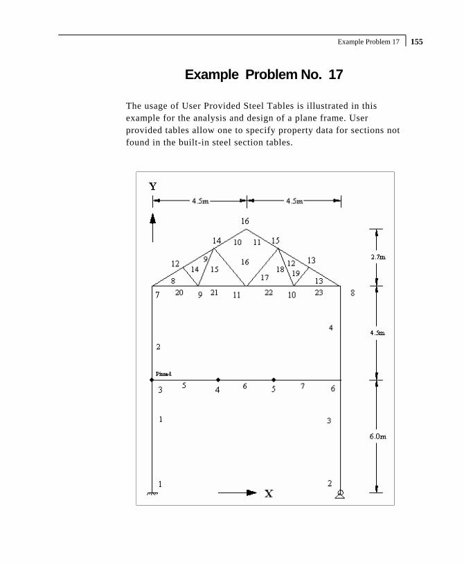
Example Problem 17 155
Example Problem No. 17
The usage of User Provided Steel Tables is illustrated in this example for the analysis and design of a plane frame. User provided tables allow one to specify property data for sections not found in the built-in steel section tables.

Part I - Application Examples Example Problem 17 156
Actual input is shown in bold lettering followed by explanation. STAAD PLANE EXAMPLE FOR USER TABLE
Every input file has to start with the command STAAD. The PLANE command is used to designate the structure as a plane frame.
UNIT METER KNS
The UNIT command sets the length and force units to be used. JOINT COORDINATES 1 0. 0. ; 2 9 0 ; 3 0 6 0 6 9 6 0 7 0 10.5 ; 8 9 10.5 ; 9 2.25 10.5 ; 10 6.75 10.5 11 4.5 10.5 ; 12 1.5 11.4 ; 13 7.5 11.4 14 3.0 12.3 ; 15 6.0 12.3; 16 4.5 13.2
The above set of data is used to provide joint coordinates for the various joints of the structure. The cartesian system is being used here. The data consists of the joint number followed by global X and Y coordinates. Note that for a space frame, the Z coordinate(s) need to be provided also. In the above input, semicolon (;) signs are used as line separators. This allows the user to provide multiple sets of data on one line.
MEMBER INCIDENCES 1 1 3 ; 2 3 7 ; 3 2 6 ; 4 6 8 ; 5 3 4 6 4 5 ; 7 5 6 ; 8 7 12 ; 9 12 14 10 14 16 ; 11 15 16 ; 12 13 15 ; 13 8 13 14 9 12 ; 15 9 14 ; 16 11 14 ; 17 11 15 18 10 15 ; 19 10 13 ; 20 7 9 21 9 11 ; 22 10 11 ; 23 8 10
The above data set contains the member incidence information or the joint connectivity data for each member. This completes the geometry of the structure.

Example Problem 17 157
START USER TABLE
This command is utilized to set up a User Provided steel table. All user provided steel tables must start with this command.
TABLE 1
Each table needs an unique numerical identification. The above command starts setting up Table no. 1. Upto twenty tables may be specified per run.
UNIT CM WIDE FLANGE
This command is used to specify the section-type as WIDE FLANGE in this table. Note that several section-types such as WIDE FLANGE, CHANNEL, ANGLE, TEE etc. are available for specification (See section 5 of the Technical Reference Manual).
BEAM250 32.2 25.5 0.6 10.2 0.85 3400 150 6.2 15.7 15.4 BEAM300 47.5 30.4 0.72 12.4 1.07 7160 335 14.3 21.9 23.8 BEAM350 64.6 35.6 0.73 17.2 1.15 14150 970 22.8 26.0 35.5
The above data set is used to specify the properties of three wide flange sections. The data for each section consists of two parts. In the first line, the section-name is provided. The user is allowed to provide any section name within twelve characters. The second line contains the section properties required for the particular section-type. Each section-type requires a certain number of data (area of cross-section, depth, moment of inertias etc.) provided in a certain order. For example, in this case, for wide flanges, ten different properties are required. For detailed information on the various properties required for the different section-types and their order of specification, refer to section 5.19 in the STAAD Technical Reference Manual. Without exception, all required properties for the particular section-type must be provided.

Part I - Application Examples Example Problem 17 158
TABLE 2 UNIT CM ANGLES L30305 3.0 3.0 0.5 0.58 1.0 1.0 L40405 4.0 4.0 0.5 0.78 1.33 1.33 L50505 5.0 5.0 0.5 0.98 1.67 1.67
The above command and data lines set up another user provided table consisting of angle sections.
END
This command signifies the end of the user provided table data set. All user provided table related input must be terminated with this command.
MEMBER PROPERTIES 1 3 4 UPT 1 BEAM350 2 UPT 1 BEAM300 ; 5 6 7 UPT 1 BEAM250 8 TO 13 UPT 1 BEAM250 14 TO 19 UPT 2 L30305 20 TO 23 UPT 2 L40405
In the above command lines, the member properties are being assigned from the user provided tables created earlier. The word UPT signifies that the properties are from the user provided table. This is followed by the table number and then the section name as specified in the user provided table. The numbers 1 or 2 following the word UPT indicate the table from which section names are fetched.
MEMBER TRUSS 14 TO 23
The above command is used to designate members 14 to 23 as truss members.

Example Problem 17 159
MEMBER RELEASE 5 START MZ
The MEMBER RELEASE command is used to release the MZ moment at the start joint of member no. 5.
CONSTANTS E STEEL DENSITY STEEL ALL POISSON STEEL ALL BETA 90.0 MEMB 3 4
The above command set is used to specify modulus of elasticity, density, Poisson’s ratio and beta angle values. Built-in default value of steel is used for the material constants.
UNIT KNS METER
The force unit is reset to KNS, and length unit to METER using this command.
SUPPORT 1 FIXED ; 2 PINNED
The above command set is used to designate supports. Here, joint 1 is designated as a fixed support and joint 2 is designated as a pinned support.
LOADING 1 DEAD AND LIVE LOAD SELFWEIGHT Y -1.0 JOINT LOAD 4 5 FY -65. ; 11 FY -155. MEMB LOAD 8 TO 13 UNI Y –13.5 ; 6 UNI GY –17.5
The above command set is used to specify the loadings on the structure. In this case, dead and live loads are provided through load case 1. It consists of selfweight, concentrated loads at joints 4, 5 and 11, and distributed loads on some members.

Part I - Application Examples Example Problem 17 160
PERFORM ANALYSIS
This command instructs the program to execute the analysis at this point.
PARAMETER CODE BRITISH BEAM 1.0 ALL NSF 0.85 ALL KY 1.2 MEMB 3 4
The above commands are used to specify parameters for steel design.
CHECK CODE MEMBER 3 19 SELECT MEMBER 20
This command will perform a code check on members 3 and 19 per the BRITISH steel design code. A member selection too is performed for member 20. For each member, the member selection will be performed from the table that was originally used for the specification of the member property. In this case, the selection will be from the respective user tables from which the properties were initially assigned. It may be noted that properties may be provided (and selection may be performed) from built-in steel tables and user provided tables in the same data file.
FINISH
This command terminates a STAAD run.

Example Problem 17 161
**************************************************** * * * STAAD.Pro * * Version 2007 Build 02 * * Proprietary Program of * * Research Engineers, Intl. * * Date= * * Time= * * * * USER ID: * **************************************************** 1. STAAD PLANE EXAMPLE FOR USER TABLE 2. UNIT METER KNS 3. JOINT COORDINATES 4. 1 0. 0. ; 2 9 0 ; 3 0 6 0 6 9 6 0 5. 7 0 10.5 ; 8 9 10.5 ; 9 2.25 10.5 ; 10 6.75 10.5 6. 11 4.5 10.5 ; 12 1.5 11.4 ; 13 7.5 11.4 7. 14 3.0 12.3 ; 15 6.0 12.3; 16 4.5 13.2 8. MEMBER INCIDENCES 9. 1 1 3 ; 2 3 7 ; 3 2 6 ; 4 6 8 ; 5 3 4 10. 6 4 5 ; 7 5 6 ; 8 7 12 ; 9 12 14 11. 10 14 16 ; 11 15 16 ; 12 13 15 ; 13 8 13 12. 14 9 12 ; 15 9 14 ; 16 11 14 ; 17 11 15 13. 18 10 15 ; 19 10 13 ; 20 7 9 14. 21 9 11 ; 22 10 11 ; 23 8 10 15. START USER TABLE 16. TABLE 1 17. UNIT CM 18. WIDE FLANGE 19. BEAM250 20. 32.2 25.5 0.6 10.2 0.85 3400 150 6.2 15.7 15.4 21. BEAM300 22. 47.5 30.4 0.72 12.4 1.07 7160 335 14.3 21.9 23.8 23. BEAM350 24. 64.6 35.6 0.73 17.2 1.15 14150 970 22.8 26.0 35.5 25. TABLE 2 26. UNIT CM 27. ANGLES 28. L30305 29. 3.0 3.0 0.5 0.58 1.0 1.0 30. L40405 31. 4.0 4.0 0.5 0.78 1.33 1.33 32. L50505 33. 5.0 5.0 0.5 0.98 1.67 1.67 34. END 35. MEMBER PROPERTIES 36. 1 3 4 UPT 1 BEAM350 37. 2 UPT 1 BEAM300 ; 5 6 7 UPT 1 BEAM250 38. 8 TO 13 UPT 1 BEAM250 39. 14 TO 19 UPT 2 L30305 40. 20 TO 23 UPT 2 L40405 41. MEMBER TRUSS 42. 14 TO 23 43. MEMBER RELEASE 44. 5 START MZ 45. CONSTANTS 46. E STEEL ALL 47. DENSITY STEEL ALL 48. POISSON STEEL ALL 49. BETA 90.0 MEMB 3 4 50. UNIT KNS METER 51. SUPPORT 52. 1 FIXED ; 2 PINNED 53. LOADING 1 DEAD AND LIVE LOAD 54. SELFWEIGHT Y -1.0 55. JOINT LOAD 56. 4 5 FY -65. ; 11 FY -155. 57. MEMB LOAD 58. 8 TO 13 UNI Y -13.5 ; 6 UNI GY -17.5

Part I - Application Examples Example Problem 17 162
59. PERFORM ANALYSIS P R O B L E M S T A T I S T I C S ----------------------------------- NUMBER OF JOINTS/MEMBER+ELEMENTS/SUPPORTS = 16/ 23/ 2 SOLVER USED IS THE IN-CORE ADVANCED SOLVER TOTAL PRIMARY LOAD CASES = 1, TOTAL DEGREES OF FREEDOM = 43 ZERO STIFFNESS IN DIRECTION 6 AT JOINT 9 EQN.NO. 22 LOADS APPLIED OR DISTRIBUTED HERE FROM ELEMENTS WILL BE IGNORED. THIS MAY BE DUE TO ALL MEMBERS AT THIS JOINT BEING RELEASED OR EFFECTIVELY RELEASED IN THIS DIRECTION. ZERO STIFFNESS IN DIRECTION 6 AT JOINT 10 EQN.NO. 25 ZERO STIFFNESS IN DIRECTION 6 AT JOINT 11 EQN.NO. 28 60. PARAMETER 61. CODE BRITISH 62. BEAM 1.0 ALL 63. NSF 0.85 ALL 64. KY 1.2 MEMB 3 4 65. CHECK CODE MEMBER 3 19 STAAD.Pro CODE CHECKING - (BSI ) *********************** PROGRAM CODE REVISION V2.10_5950-1_2000 ALL UNITS ARE - KNS METE (UNLESS OTHERWISE NOTED) MEMBER TABLE RESULT/ CRITICAL COND/ RATIO/ LOADING/ FX MY MZ LOCATION ======================================================================= * 3 ST BEAM350 FAIL BS-4.8.3.3.1 2.472 1 246.69 C 52.86 0.00 - * 19 ST L30305 FAIL BS-4.7 (C) 1.654 1 18.19 C 0.00 0.00 0.00 ************** END OF TABULATED RESULT OF DESIGN ************** 66. SELECT MEMBER 20

Example Problem 17 163
STAAD.Pro MEMBER SELECTION - (BSI ) ************************** PROGRAM CODE REVISION V2.10_5950-1_2000 ALL UNITS ARE - KNS METE (UNLESS OTHERWISE NOTED) MEMBER TABLE RESULT/ CRITICAL COND/ RATIO/ LOADING/ FX MY MZ LOCATION ======================================================================= 20 ST L30305 PASS BS-4.6 (T) 0.970 1 62.38 T 0.00 0.00 0.00 ************** END OF TABULATED RESULT OF DESIGN ************** 67. FINISH **************************************************************************** **WARNING** SOME MEMBER SIZES HAVE CHANGED SINCE LAST ANALYSIS. IN THE POST PROCESSOR, MEMBER QUERIES WILL USE THE LAST ANALYSIS FORCES WITH THE UPDATED MEMBER SIZES. TO CORRECT THIS INCONSISTENCY, PLEASE DO ONE MORE ANALYSIS. FROM THE UPPER MENU, PRESS RESULTS, UPDATE PROPERTIES, THEN FILE SAVE; THEN ANALYZE AGAIN WITHOUT THE GROUP OR SELECT COMMANDS. **************************************************************************** *********** END OF THE STAAD.Pro RUN *********** **** DATE= TIME= **** ************************************************************ * For questions on STAAD.Pro, please contact * * Research Engineers Offices at the following locations * * * * Telephone Email * * USA: +1 (714)974-2500 [email protected] * * CANADA +1 (905)632-4771 [email protected] * * UK +44(1454)207-000 [email protected] * * FRANCE +33(0)1 64551084 [email protected] * * GERMANY +49/931/40468-71 [email protected] * * NORWAY +47 67 57 21 30 [email protected] * * SINGAPORE +65 6225-6158 [email protected] * * INDIA +91(033)4006-2021 [email protected] * * JAPAN +81(03)5952-6500 [email protected] * * CHINA +86(411)363-1983 [email protected] * * THAILAND +66(0)2645-1018/19 [email protected] * * * * North America [email protected] * * Europe [email protected] * * Asia [email protected] * ************************************************************

Part I - Application Examples Example Problem 17 164
NOTES

Example Problem 18 165
Example Problem No. 18
This is an example which demonstrates the calculation of principal stresses on a finite element.
Fixed Supports at Joints 1, 2, 3, 4, 5, 9, 13 Load intensity = 2000 Kn/sq.m in - Y direction

Part I - Application Examples Example Problem 18 166
Actual input is shown in bold lettering followed by explanation. STAAD SPACE SAMPLE CALCULATION FOR * ELEMENT STRESSES
Every input has to start with the word STAAD. The word SPACE signifies that the structure is a space frame (3-D structure).
UNIT METER KNS
Specifies the unit to be used. JOINT COORDINATES 1 0 0 0 4 9 0 0 REPEAT 3 0 0 3
Joint number followed by X, Y and Z coordinates are provided above. The REPEAT command is used to generate coordinates of joints 5 to 16 based on the pattern of joints 1 to 4.
ELEMENT INCIDENCE 1 1 5 6 2 TO 3 REPEAT 2 3 4
Element connectivities of elements 1 to 3 are defined first, based on which, the connectivities of elements 4 to 9 are generated.
ELEMENT PROPERTIES 1 TO 9 THICK 0.25
Elements 1 to 9 have a thickness of 0.25 m. CONSTANTS E CONCRETE ALL POISSON CONC ALL
Modulus of Elasticity and Poisson’s ratio of all the elements is that of the built-in default value for concrete.

Example Problem 18 167
SUPPORT 1 TO 4 5 9 13 FIXED
"Fixed support" conditions exist at the above mentioned joints.
LOAD 1 ELEMENT LOAD 1 TO 9 PRESSURE -2000.0
A uniform pressure of 2000 Kn/sq.m is applied on all the elements. In the absence of an explicit direction specification, the load is assumed to act along the local Z axis. The negative value indicates that the load acts opposite to the positive direction of the local Z.
PERFORM ANALYSIS
The above command instructs the program to proceed with the analysis.
PRINT SUPPORT REACTION
The above command is self-explanatory. UNIT MMS PRINT ELEMENT STRESSES LIST 4
Element stresses at the centroid of the element are printed using the above command. The output includes membrane stresses, shear stresses, bending moments per unit width and principal stresses. The change of length unit from metre to mms indicates that the values will be printed in KN and MMs units.
FINISH
The STAAD run is terminated.

Part I - Application Examples Example Problem 18 168
**************************************************** * * * STAAD.Pro * * Version 2007 Build 02 * * Proprietary Program of * * Research Engineers, Intl. * * Date= * * Time= * * * * USER ID: * **************************************************** 1. STAAD SPACE SAMPLE CALCULATION FOR 2. * ELEMENT STRESSES 3. UNIT METER KNS 4. JOINT COORDINATES 5. 1 0 0 0 4 9 0 0 6. REPEAT 3 0 0 3 7. ELEMENT INCIDENCE 8. 1 1 5 6 2 TO 3 9. REPEAT 2 3 4 10. ELEMENT PROPERTIES 11. 1 TO 9 THICK 0.25 12. CONSTANTS 13. E CONCRETE ALL 14. POISSON CONC ALL 15. SUPPORT 16. 1 TO 4 5 9 13 FIXED 17. LOAD 1 18. ELEMENT LOAD 19. 1 TO 9 PRESSURE -2000.0 20. PERFORM ANALYSIS P R O B L E M S T A T I S T I C S ----------------------------------- NUMBER OF JOINTS/MEMBER+ELEMENTS/SUPPORTS = 16/ 9/ 7 SOLVER USED IS THE IN-CORE ADVANCED SOLVER TOTAL PRIMARY LOAD CASES = 1, TOTAL DEGREES OF FREEDOM = 54 21. PRINT SUPPORT REACTION SUPPORT REACTIONS -UNIT KNS METE STRUCTURE TYPE = SPACE ----------------- JOINT LOAD FORCE-X FORCE-Y FORCE-Z MOM-X MOM-Y MOM Z 1 1 0.00 -1219.71 0.00 -391.04 0.00 391.04 2 1 0.00 8767.13 0.00 -26681.65 0.00 -525.26 3 1 0.00 37676.28 0.00 -88169.71 0.00 2984.47 4 1 0.00 35166.44 0.00 -66475.53 0.00 -24034.21 5 1 0.00 8767.13 0.00 525.26 0.00 26681.65 9 1 0.00 37676.28 0.00 -2984.47 0.00 88169.71 13 1 0.00 35166.44 0.00 24034.21 0.00 66475.53 ************** END OF LATEST ANALYSIS RESULT ************** 22. UNIT MMS 23. PRINT ELEMENT STRESSES LIST 4

Example Problem 18 169
ELEMENT STRESSES FORCE,LENGTH UNITS= KNS MMS ---------------- STRESS = FORCE/UNIT WIDTH/THICK, MOMENT = FORCE-LENGTH/UNIT WIDTH ELEMENT LOAD SQX SQY MX MY MXY VONT VONB SX SY SXY TRESCAT TRESCAB 4 1 0.02 -0.02 2111.90 10726.39 4553.75 1.21 1.21 0.00 0.00 0.00 1.22 1.22 TOP : SMAX= 1.22 SMIN= 0.01 TMAX= 0.60 ANGLE= -23.3 BOTT: SMAX= -0.01 SMIN= -1.22 TMAX= 0.60 ANGLE= -23.3 **** MAXIMUM STRESSES AMONG SELECTED PLATES AND CASES **** MAXIMUM MINIMUM MAXIMUM MAXIMUM MAXIMUM PRINCIPAL PRINCIPAL SHEAR VONMISES TRESCA STRESS STRESS STRESS STRESS STRESS 1.217974E+00 -1.217974E+00 6.017370E-01 1.210789E+00 1.217974E+00 PLATE NO. 4 4 4 4 4 CASE NO. 1 1 1 1 1 ********************END OF ELEMENT FORCES******************** 24. FINISH *********** END OF THE STAAD.Pro RUN *********** **** DATE= TIME= **** ************************************************************ * For questions on STAAD.Pro, please contact * * Research Engineers Offices at the following locations * * * * Telephone Email * * USA: +1 (714)974-2500 [email protected] * * CANADA +1 (905)632-4771 [email protected] * * UK +44(1454)207-000 [email protected] * * FRANCE +33(0)1 64551084 [email protected] * * GERMANY +49/931/40468-71 [email protected] * * NORWAY +47 67 57 21 30 [email protected] * * SINGAPORE +65 6225-6158 [email protected] * * INDIA +91(033)4006-2021 [email protected] * * JAPAN +81(03)5952-6500 [email protected] * * CHINA +86(411)363-1983 [email protected] * * THAILAND +66(0)2645-1018/19 [email protected] * * * * North America [email protected] * * Europe [email protected] * * Asia [email protected] * ************************************************************

Part I - Application Examples Example Problem 18 170
Calculation of principal stresses for element 4 Calculations are presented for the top surface only.
SX = 0.0 kN/mm2
SY = 0.0 kN/mm2
SXY = 0.0 kN/mm2
MX = 2111.84 kN-mm/mm MY = 10726.22 kN-mm/mm MXY = 4553.97 kN-mm/mm S = 1/6t2 = 1/6*2502 = 10416.67mm2 (Section Modulus) σx = 67.10416
84.21110.0SMXSX +=+
= 0.2027 kN/mm2 σy = 67.10416
22.107260.0SMYSY +=+
= 1.0297 kN/mm2 τxy = 67.10416
97.45530.0SMXYSXY +=+
= 0.4372 kN/mm2
TMAX x yxy=
−+
22
4( )σ σ
τ
24372.04
)0297.12027.0(2
TMAX +−
=
= 0.6018 kN/mm2

Example Problem 18 171
( )x y TMAXσ σ+
+2
SMAX =
= 6018.02)0297.12027.0( ++
= 1.218 kN/mm2 say 1.22 kN/mm2
SMIN = ( )x y TMAXσ σ+
−2
= 6018.02)0297.12027.0( −+
= 0.0144 kN/mm2 say 0.01 kN/ mm2
Angle xy
x y
=−
⎧⎨⎪
⎩⎪
⎫⎬⎪
⎭⎪−1
221tanτ
σ σ
⎭⎬⎫
⎩⎨⎧
−−= 0297.12027.0
4372.0*21tan21
= -23.3o

Part I - Application Examples Example Problem 18 172
NOTES
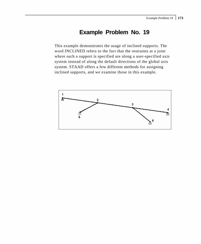
Example Problem 19 173
Example Problem No. 19
This example demonstrates the usage of inclined supports. The word INCLINED refers to the fact that the restraints at a joint where such a support is specified are along a user-specified axis system instead of along the default directions of the global axis system. STAAD offers a few different methods for assigning inclined supports, and we examine those in this example.

Part I - Application Examples Example Problem 19 174
Actual input is shown in bold lettering followed by explanation.
STAAD SPACE INPUT WIDTH 79
Every input has to start with the word STAAD. The word SPACE signifies that the structure is a space frame structure (3-D) and the geometry is defined through X, Y and Z coordinates.
UNIT METER KN
Specifies the unit to be used for data to follow. JOINT COORDINATES 1 0 5 0; 2 10 5 10; 3 20 5 20; 4 30 5 30; 5 5 0 5; 6 25 0 25;
Joint number followed by X, Y and Z coordinates are provided above. Semicolon signs (;) are used as line separators. That enables us to provide multiple sets of data on one line.
MEMBER INCIDENCES 1 1 2; 2 2 3; 3 3 4; 4 5 2; 5 6 3;
Defines the members by the joints they are connected to. UNIT MMS KN MEMBER PROPERTY AMERICAN 4 5 PRIS YD 800 1 TO 3 PRIS YD 750 ZD 500
Properties for all members of the model are provided using the PRISMATIC option. YD and ZD stand for depth and width. If ZD is not provided, a circular shape with diameter = YD is assumed for that cross section. All properties required for the analysis, such as, Area, Moments of Inertia, etc. are calculated automatically from these dimensions unless these are explicitly defined. The values are provided in MMS unit.

Example Problem 19 175
CONSTANTS E CONCRETE ALL POISSON CONCRETE ALL DENSITY CONCRETE ALL
Material constants like E (modulus of elasticity) and Poisson’s ratio are specified following the command CONSTANTS.
UNIT METER KN SUPPORTS 5 INCLINED REF 10 5 10 FIXED BUT MX MY MZ KFX 30000 6 INCLINED REFJT 3 FIXED BUT MX MY MZ KFX 30000 1 PINNED 4 INCLINED 1 0 1 FIXED BUT FX MX MY MZ
We assign supports (restraints) at 4 nodes - 5, 6, 1 and 4. For 3 of those, namely, 5, 6 and 4, the node number is followed by the keyword INCLINED, signifying that an INCLINED support is defined there. For the remaining one - node 1 - that keyword is missing. Hence, the support at node 1 is a global direction support. The most important aspect of inclined supports is their axis system. Each node where an inclined support is defined has its own distinct local X, local Y and local Z axes. In order to define the axis system, we first have to define a datum point. The support node and the datum point together help define the axis system. 3 different methods are shown in the above 3 instances for defining the datum point. At node 5, notice the keyword REF followed by the numbers (10,5,10). This means that the datum point associated with node 5 is one which has the global coordinates of (10m, 5m, 10m). Coincidentally, this happens to be node 2. At node 6, the keyword REFJT is used followed by the number 3. This means that the datum point for support node 6 is the joint number 3 of the model. The coordinates of the datum point are hence those of node 3, namely, (20m, 5m and 20m).

Part I - Application Examples Example Problem 19 176
At node 4, the word INCLINED is merely followed by 3 numbers (1,0,1). In the absence of the words REF and REFJT, the program sets the datum point to be the following. It takes the coordinates of node 4, which are (30m,5m,30m) and adds to them, the 3 numbers which comes after the word INCLINED. Thus, the datum point becomes (31m, 5m and 31m). Once the datum point is established, the local axis system is defined as follows. Local X is a straight line (vector) pointing from the support node towards the datum point. Local Z is the vector obtained by the cross product of local X and the global Y axis (unless the SET Z UP command is used in which case one would use global Z instead of global Y and that would yield local Y). Local Y is the vector resulting from the cross product of local Z and local X. The right hand rule must be used when performing these cross products. Notice the unique nature of these datum points. The one for node 5 tells us that a line connecting nodes 5 to 2 is the local X axis, and is hence along the axis of member 4. By defining a KFX spring at that one, we are saying that the lower end of member 4 can move along its axis like the piston of a car engine. Think of a pile bored into rock with a certain amount of freedom to expand and contract axially. The same is true for the support at the bottom of member 5. The local X axis of that support is along the axis of member 5. That also happens to be the case for the supported end of member 3. The line going from node 4 to the datum point (31,5,31) happens to be coincident with the axis of the member, or the traffic direction. The expression FIXED BUT FX MX MY MZ for that support indicates that it is free to translate along local X, suggesting that it is an expansion joint - free to expand or contract along the axis of member 3. Since MX, MY and MZ are all released at these supports, no moment will be resisted by these supports.

Example Problem 19 177
LOAD 1 DEAD LOAD SELFWEIGHT Y -1.2 LOAD 2 LIVE LOAD MEMBER LOAD 1 TO 3 UNI GY -6 LOAD COMB 3 1 1.0 2 1.0 PERFORM ANALYSIS PRINT STATICS CHECK
3 load cases followed by the instruction for the type of analysis are specified. The PRINT STATICS CHECK option will instruct the program to produce a report consisting of total applied load versus total reactions from the supports for each primary load case.
PRINT SUPPORT REACTION
By default, support reactions are printed in the global axis directions. The above command is an instruction for such a report.
SET INCLINED REACTION PRINT SUPPORT REACTION
Just earlier, we saw how to obtain support reactions in the global axis system. What if we need them in the inclined axis system? The “SET INCLINED REACTION” is a switch for that purpose. It tells the program that reactions should be reported in the inclined axis system instead of the global axis system. This has to be followed by the PRINT SUPPORT REACTIONS command.
PRINT MEMBER FORCES PRINT JOINT DISP FINISH
Member forces are reported in the local axis system of the members. Joint displacements at all joints are reported in the global axis system. Following this, the STAAD run is terminated.

Part I - Application Examples Example Problem 19 178
**************************************************** * * * STAAD.Pro * * Version 2007 Build 02 * * Proprietary Program of * * Research Engineers, Intl. * * Date= * * Time= * * * * USER ID: * **************************************************** 1. STAAD SPACE 2. INPUT WIDTH 79 3. UNIT METER KN 4. JOINT COORDINATES 5. 1 0 5 0; 2 10 5 10; 3 20 5 20; 4 30 5 30; 5 5 0 5; 6 25 0 25 6. MEMBER INCIDENCES 7. 1 1 2; 2 2 3; 3 3 4; 4 5 2; 5 6 3 8. UNIT MMS KN 9. MEMBER PROPERTY AMERICAN 10. 4 5 PRIS YD 800 11. 1 TO 3 PRIS YD 750 ZD 500 12. CONSTANTS 13. E CONCRETE ALL 14. POISSON CONCRETE ALL 15. DENSITY CONCRETE ALL 16. UNIT METER KN 17. SUPPORTS 18. 5 INCLINED REF 10 5 10 FIXED BUT MX MY MZ KFX 30000 19. 6 INCLINED REFJT 3 FIXED BUT MX MY MZ KFX 30000 20. 1 PINNED 21. 4 INCLINED 1 0 1 FIXED BUT FX MX MY MZ 22. LOAD 1 DEAD LOAD 23. SELFWEIGHT Y -1.2 24. LOAD 2 LIVE LOAD 25. MEMBER LOAD 26. 1 TO 3 UNI GY -6 27. LOAD COMB 3 28. 1 1.0 2 1.0 29. PERFORM ANALYSIS PRINT STATICS CHECK P R O B L E M S T A T I S T I C S ----------------------------------- NUMBER OF JOINTS/MEMBER+ELEMENTS/SUPPORTS = 6/ 5/ 4 SOLVER USED IS THE IN-CORE ADVANCED SOLVER TOTAL PRIMARY LOAD CASES = 2, TOTAL DEGREES OF FREEDOM = 27 STATIC LOAD/REACTION/EQUILIBRIUM SUMMARY FOR CASE NO. 1 DEAD LOAD ***TOTAL APPLIED LOAD ( KN METE ) SUMMARY (LOADING 1 ) SUMMATION FORCE-X = 0.00 SUMMATION FORCE-Y = -696.00 SUMMATION FORCE-Z = 0.00 SUMMATION OF MOMENTS AROUND THE ORIGIN- MX= 10439.93 MY= 0.00 MZ= -10439.93 ***TOTAL REACTION LOAD( KN METE ) SUMMARY (LOADING 1 ) SUMMATION FORCE-X = 0.00 SUMMATION FORCE-Y = 696.00 SUMMATION FORCE-Z = 0.00 SUMMATION OF MOMENTS AROUND THE ORIGIN- MX= -10439.93 MY= 0.00 MZ= 10439.93

Example Problem 19 179
MAXIMUM DISPLACEMENTS ( CM /RADIANS) (LOADING 1) MAXIMUMS AT NODE X = -7.99237E-01 5 Y = -2.49498E+00 3 Z = -7.99237E-01 5 RX= -2.66161E-03 4 RY= 6.12828E-16 4 RZ= 2.66161E-03 4 STATIC LOAD/REACTION/EQUILIBRIUM SUMMARY FOR CASE NO. 2 LIVE LOAD ***TOTAL APPLIED LOAD ( KN METE ) SUMMARY (LOADING 2 ) SUMMATION FORCE-X = 0.00 SUMMATION FORCE-Y = -254.56 SUMMATION FORCE-Z = 0.00 SUMMATION OF MOMENTS AROUND THE ORIGIN- MX= 3818.38 MY= 0.00 MZ= -3818.38 ***TOTAL REACTION LOAD( KN METE ) SUMMARY (LOADING 2 ) SUMMATION FORCE-X = 0.00 SUMMATION FORCE-Y = 254.56 SUMMATION FORCE-Z = 0.00 SUMMATION OF MOMENTS AROUND THE ORIGIN- MX= -3818.38 MY= 0.00 MZ= 3818.38 MAXIMUM DISPLACEMENTS ( CM /RADIANS) (LOADING 2) MAXIMUMS AT NODE X = -2.97411E-01 5 Y = -9.31566E-01 3 Z = -2.97411E-01 5 RX= -1.18888E-03 4 RY= 2.28152E-16 4 RZ= 1.18888E-03 4 ************ END OF DATA FROM INTERNAL STORAGE ************ 30. PRINT SUPPORT REACTION SUPPORT REACTIONS -UNIT KN METE STRUCTURE TYPE = SPACE ----------------- JOINT LOAD FORCE-X FORCE-Y FORCE-Z MOM-X MOM-Y MOM Z 5 1 215.36 288.60 215.36 0.00 0.00 0.00 2 86.45 94.77 86.45 0.00 0.00 0.00 3 301.81 383.37 301.81 0.00 0.00 0.00 6 1 -212.20 286.84 -212.20 0.00 0.00 0.00 2 -85.19 94.06 -85.19 0.00 0.00 0.00 3 -297.39 380.91 -297.39 0.00 0.00 0.00 1 1 -3.15 60.21 -3.15 0.00 0.00 0.00 2 -1.27 32.84 -1.27 0.00 0.00 0.00 3 -4.42 93.05 -4.42 0.00 0.00 0.00 4 1 0.00 60.33 0.00 0.00 0.00 0.00 2 0.00 32.89 0.00 0.00 0.00 0.00 3 0.00 93.22 0.00 0.00 0.00 0.00 ************** END OF LATEST ANALYSIS RESULT ************** 31. SET INCLINED REACTION 32. PRINT SUPPORT REACTION

Part I - Application Examples Example Problem 19 180
SUPPORT REACTIONS -UNIT KN METE STRUCTURE TYPE = SPACE ----------------- JOINT LOAD FORCE-X FORCE-Y FORCE-Z MOM-X MOM-Y MOM Z 5 1 415.30 59.81 0.00 0.00 0.00 0.00 2 154.54 6.79 0.00 0.00 0.00 0.00 3 569.83 66.60 0.00 0.00 0.00 0.00 6 1 410.64 60.94 0.00 0.00 0.00 0.00 2 152.67 7.25 0.00 0.00 0.00 0.00 3 563.31 68.19 0.00 0.00 0.00 0.00 1 1 -3.15 60.21 -3.15 0.00 0.00 0.00 2 -1.27 32.84 -1.27 0.00 0.00 0.00 3 -4.42 93.05 -4.42 0.00 0.00 0.00 4 1 0.00 60.33 0.00 0.00 0.00 0.00 2 0.00 32.89 0.00 0.00 0.00 0.00 3 0.00 93.22 0.00 0.00 0.00 0.00 ************** END OF LATEST ANALYSIS RESULT ************** 33. PRINT MEMBER FORCES MEMBER END FORCES STRUCTURE TYPE = SPACE ----------------- ALL UNITS ARE -- KN METE (LOCAL ) MEMBER LOAD JT AXIAL SHEAR-Y SHEAR-Z TORSION MOM-Y MOM-Z 1 1 1 -4.46 60.21 0.00 0.00 0.00 0.00 2 4.46 89.73 0.00 0.00 0.00 -208.74 2 1 -1.79 32.84 0.00 0.00 0.00 0.00 2 1.79 52.01 0.00 0.00 0.00 -135.58 3 1 -6.25 93.05 0.00 0.00 0.00 0.00 2 6.25 141.75 0.00 0.00 0.00 -344.32 2 1 2 300.10 75.79 0.00 0.00 0.00 125.95 3 -300.10 74.15 0.00 0.00 0.00 -114.37 2 2 120.47 42.75 0.00 0.00 0.00 76.77 3 -120.47 42.10 0.00 0.00 0.00 -72.12 3 2 420.57 118.55 0.00 0.00 0.00 202.71 3 -420.57 116.25 0.00 0.00 0.00 -186.49 3 1 3 0.00 89.61 0.00 0.00 0.00 207.02 4 0.00 60.33 0.00 0.00 0.00 0.00 2 3 0.00 51.96 0.00 0.00 0.00 134.89 4 0.00 32.89 0.00 0.00 0.00 0.00 3 3 0.00 141.58 0.00 0.00 0.00 341.90 4 0.00 93.22 0.00 0.00 0.00 0.00 4 1 5 415.30 59.81 0.00 0.00 0.00 0.00 2 -344.24 40.69 0.00 0.00 0.00 82.79 2 5 154.54 6.79 0.00 0.00 0.00 0.00 2 -154.54 -6.79 0.00 0.00 0.00 58.81 3 5 569.83 66.60 0.00 0.00 0.00 0.00 2 -498.77 33.90 0.00 0.00 0.00 141.61 5 1 6 410.64 60.94 0.00 0.00 0.00 0.00 3 -339.58 39.55 0.00 0.00 0.00 92.64 2 6 152.67 7.25 0.00 0.00 0.00 0.00 3 -152.67 -7.25 0.00 0.00 0.00 62.77 3 6 563.31 68.19 0.00 0.00 0.00 0.00 3 -492.25 32.30 0.00 0.00 0.00 155.41 ************** END OF LATEST ANALYSIS RESULT **************

Example Problem 19 181
34. PRINT JOINT DISP JOINT DISPLACEMENT (CM RADIANS) STRUCTURE TYPE = SPACE ------------------ JOINT LOAD X-TRANS Y-TRANS Z-TRANS X-ROTAN Y-ROTAN Z-ROTAN 1 1 0.0000 0.0000 0.0000 0.0026 0.0000 -0.0026 2 0.0000 0.0000 0.0000 0.0012 0.0000 -0.0012 3 0.0000 0.0000 0.0000 0.0038 0.0000 -0.0038 2 1 0.0005 -2.4510 0.0005 0.0007 0.0000 -0.0007 2 0.0002 -0.9139 0.0002 0.0003 0.0000 -0.0003 3 0.0008 -3.3649 0.0008 0.0011 0.0000 -0.0011 3 1 -0.0363 -2.4950 -0.0363 -0.0007 0.0000 0.0007 2 -0.0146 -0.9316 -0.0146 -0.0003 0.0000 0.0003 3 -0.0509 -3.4265 -0.0509 -0.0011 0.0000 0.0011 4 1 -0.0363 0.0000 -0.0363 -0.0027 0.0000 0.0027 2 -0.0146 0.0000 -0.0146 -0.0012 0.0000 0.0012 3 -0.0509 0.0000 -0.0509 -0.0039 0.0000 0.0039 5 1 -0.7992 -0.7992 -0.7992 0.0023 0.0000 -0.0023 2 -0.2974 -0.2974 -0.2974 0.0007 0.0000 -0.0007 3 -1.0966 -1.0966 -1.0966 0.0031 0.0000 -0.0031 6 1 0.7903 -0.7903 0.7903 -0.0024 0.0000 0.0024 2 0.2938 -0.2938 0.2938 -0.0008 0.0000 0.0008 3 1.0841 -1.0841 1.0841 -0.0032 0.0000 0.0032 ************** END OF LATEST ANALYSIS RESULT ************** 35. FINISH *********** END OF THE STAAD.Pro RUN *********** **** DATE= TIME= **** ************************************************************ * For questions on STAAD.Pro, please contact * * Research Engineers Offices at the following locations * * * * Telephone Email * * USA: +1 (714)974-2500 [email protected] * * CANADA +1 (905)632-4771 [email protected] * * UK +44(1454)207-000 [email protected] * * FRANCE +33(0)1 64551084 [email protected] * * GERMANY +49/931/40468-71 [email protected] * * NORWAY +47 67 57 21 30 [email protected] * * SINGAPORE +65 6225-6158 [email protected] * * INDIA +91(033)4006-2021 [email protected] * * JAPAN +81(03)5952-6500 [email protected] * * CHINA +86(411)363-1983 [email protected] * * THAILAND +66(0)2645-1018/19 [email protected] * * * * North America [email protected] * * Europe [email protected] * * Asia [email protected] * ************************************************************

Part I - Application Examples Example Problem 19 182
NOTES

Example Problem 20 183
Example Problem No. 20
This example generates the geometry of a cylindrical tank structure using the cylindrical coordinate system. The tank lies on its side in this example.
1
2
3
4
5
6
7
8
9
10
11
12
13
14
15
16
17
18
19
20
21
22
23
24
1
2
3
4
5
6
7
8
9
10
11
12
13
14
15
16

Part I - Application Examples Example Problem 20 184
In this example, a cylindrical tank is modeled using finite elements. The radial direction is in the XY plane and longitudinal direction is along the Z-axis. Hence, the coordinates in the XY plane are generated using the cylindrical coordinate system.
STAAD SPACE UNIT METER KN
The type of structure (SPACE frame) and length and force units for data to follow are specified.
JOINT COORD CYLINDRICAL
The above command instructs the program that the coordinate data that follows is in the cylindrical coordinate system (r,theta,z).
1 3.5 0 0 8 3.5 315 0
Joint 1 has an 'r' of 3.5 metres, theta of 0 degrees and Z of 0 ft. Joint 8 has an 'r' of 3.5 metres, theta of 315 degrees and Z of 0 ft. The 315 degrees angle is measured counter-clockwise from the +ve direction of the X-axis. Joints 2 to 7 are generated by equal incrementation of the coordinate values between joints 1 and 8.
REPEAT 2 0 0 3.0
The REPEAT command is used to generate joints 9 through 24 by repeating twice, the pattern of joints 1 to 8 at Z-increments of 3.0 metres for each REPEAT.
PRINT JOINT COORD
The above command is used to produce a report consisting of the coordinates of all the joints in the cartesian coordinate system. Note that even though the input data was in the cylindrical coordinate system, the output is in the cartesian coordinate system.
ELEMENT INCIDENCES 1 1 2 10 9 TO 7 1 1 8 8 1 9 16 REPEAT ALL 1 8 8

Example Problem 20 185
The above 4 lines identify the element incidences of all 16 elements. Incidences of element 1 is defined as 1 2 10 9. Incidences of element 2 is generated by incrementing the joint numbers of element 1 by 1, incidences of element 3 is generated by incrementing the incidences of element 2 by 1 and so on upto element 7. Incidences of element 8 has been defined above as 8 1 9 16. The REPEAT ALL command states that the pattern of ALL the elements defined by the previous 2 lines, namely elements 1 to 8, must be REPEATED once with an element number increment of 8 and a joint number increment of 8 to generate elements 9 through 16.
PRINT ELEMENT INFO
The above command is self-explanatory. FINISH

Part I - Application Examples Example Problem 20 186
**************************************************** * * * STAAD.Pro * * Version 2007 Build 02 * * Proprietary Program of * * Research Engineers, Intl. * * Date= * * Time= * * * * USER ID: * **************************************************** 1. STAAD SPACE 2. UNIT METER KN 3. JOINT COORD CYLINDRICAL 4. 1 3.5 0 0 8 3.5 315 0 5. REPEAT 2 0 0 3.0 6. PRINT JOINT COORD JOINT COORDINATES ----------------- COORDINATES ARE METE UNIT JOINT X Y Z 1 3.500 0.000 0.000 2 2.475 2.475 0.000 3 0.000 3.500 0.000 4 -2.475 2.475 0.000 5 -3.500 0.000 0.000 6 -2.475 -2.475 0.000 7 0.000 -3.500 0.000 8 2.475 -2.475 0.000 9 3.500 0.000 3.000 10 2.475 2.475 3.000 11 0.000 3.500 3.000 12 -2.475 2.475 3.000 13 -3.500 0.000 3.000 14 -2.475 -2.475 3.000 15 0.000 -3.500 3.000 16 2.475 -2.475 3.000 17 3.500 0.000 6.000 18 2.475 2.475 6.000 19 0.000 3.500 6.000 20 -2.475 2.475 6.000 21 -3.500 0.000 6.000 22 -2.475 -2.475 6.000 23 0.000 -3.500 6.000 24 2.475 -2.475 6.000 ************ END OF DATA FROM INTERNAL STORAGE ************ 7. ELEMENT INCIDENCES 8. 1 1 2 10 9 TO 7 1 1 9. 8 8 1 9 16 10. REPEAT ALL 1 8 8 11. PRINT ELEMENT INFO

Example Problem 20 187
ELEMENT INFORMATION ------------------- ELEMENT INCIDENCES THICK POISS E G AREA NO. (METE) 1 1 2 10 9 0.000 0.000 0.00 0.00 8.0364 2 2 3 11 10 0.000 0.000 0.00 0.00 8.0364 3 3 4 12 11 0.000 0.000 0.00 0.00 8.0364 4 4 5 13 12 0.000 0.000 0.00 0.00 8.0364 5 5 6 14 13 0.000 0.000 0.00 0.00 8.0364 6 6 7 15 14 0.000 0.000 0.00 0.00 8.0364 7 7 8 16 15 0.000 0.000 0.00 0.00 8.0364 8 8 1 9 16 0.000 0.000 0.00 0.00 8.0364 9 9 10 18 17 0.000 0.000 0.00 0.00 8.0364 10 10 11 19 18 0.000 0.000 0.00 0.00 8.0364 11 11 12 20 19 0.000 0.000 0.00 0.00 8.0364 12 12 13 21 20 0.000 0.000 0.00 0.00 8.0364 13 13 14 22 21 0.000 0.000 0.00 0.00 8.0364 14 14 15 23 22 0.000 0.000 0.00 0.00 8.0364 15 15 16 24 23 0.000 0.000 0.00 0.00 8.0364 16 16 9 17 24 0.000 0.000 0.00 0.00 8.0364 ******************END OF ELEMENT INFO****************** 12. FINISH *********** END OF THE STAAD.Pro RUN *********** **** DATE= TIME= **** ************************************************************ * For questions on STAAD.Pro, please contact * * Research Engineers Offices at the following locations * * * * Telephone Email * * USA: +1 (714)974-2500 [email protected] * * CANADA +1 (905)632-4771 [email protected] * * UK +44(1454)207-000 [email protected] * * FRANCE +33(0)1 64551084 [email protected] * * GERMANY +49/931/40468-71 [email protected] * * NORWAY +47 67 57 21 30 [email protected] * * SINGAPORE +65 6225-6158 [email protected] * * INDIA +91(033)4006-2021 [email protected] * * JAPAN +81(03)5952-6500 [email protected] * * CHINA +86(411)363-1983 [email protected] * * THAILAND +66(0)2645-1018/19 [email protected] * * * * North America [email protected] * * Europe [email protected] * * Asia [email protected] * ************************************************************

Part I - Application Examples Example Problem 20 188
NOTES

Example Problem 21 189
Example Problem No. 21
This example illustrates the modeling of tension-only members using the MEMBER TENSION command.

Part I - Application Examples
Example Problem 21 190
This example has been created to illustrate the command specification for a structure with certain members capable of carrying tensile force only. It is important to note that the analysis can be done for only 1 load case at a time. This is because, the set of “active” members (and hence the stiffness matrix) is load case dependent.
STAAD PLANE EXAMPLE FOR TENSION-ONLY MEMBERS
The input data is initiated with the word STAAD. This structure is a PLANE frame.
UNIT METER KNS
Units for the commands to follow are defined above. SET NL 3
This structure has to be analysed for 3 primary load cases. Consequently, the modeling of our problem requires us to define 3 sets of data, with each set containing a load case and an associated analysis command. Also, the members which get switched off in the analysis for any load case have to be restored for the analysis for the subsequent load case. To accommodate these requirements, it is necessary to have 2 commands, one called “SET NL” and the other called “CHANGE”. The SET NL command is used above to indicate the total number of primary load cases that the file contains. The CHANGE command will come in later (after the PERFORM ANALYSIS command).
JOINT COORDINATES 1 0 0 ; 2 0 3.5 ; 3 0 7.0 ; 4 5.25 7.0 ; 5 5.25 3.5 ; 6 5.25 0
Joint coordintes of joints 1 to 6 are defined above. MEMBER INCIDENCES 1 1 2 5 6 1 5 ; 7 2 6 ; 8 2 4 ; 9 3 5 ; 10 2 5
Incidences of members 1 to 10 are defined.

Example Problem 21 191
MEMBER TENSION 6 TO 9
Members 6 to 9 are defined as TENSION-only members. Hence for each load case, if during the analysis, any of the members 6 to 9 is found to be carrying a compressive force, it is disabled from the structure and the analysis is carried out again with the modified structure.
MEMBER PROPERTY BRITISH 1 TO 10 TA ST UC152X152X30
All members have been assigned a UC section from the British table.
CONSTANTS E STEEL ALL POISSON STEEL ALL
Following the command CONSTANTS, material constants such as E (Modulus of Elasticity), and Poisson’s ratio are specified. In this case, the built-in default value of steel is assigned.
SUPPORT 1 6 PINNED
The supports are defined above. LOAD 1 JOINT LOAD 2 FX 70 3 FX 45
Load 1 is defined above and consists of joint loads at joints 2 and 3.
PERFORM ANALYSIS
An analysis is carried out for load case 1.

Part I - Application Examples
Example Problem 21 192
CHANGE MEMBER TENSION 6 TO 9
One or more among the members 6 to 9 may have been inactivated in the previous analysis. The CHANGE command restores the original structure to prepare it for the analysis for the next primary load case. The members with the tension-only attribute are specified again.
LOAD 2 JOINT LOAD 4 FX -45 5 FX -70
Load case 2 is described above. PERFORM ANALYSIS CHANGE
The instruction to analyze the structure is specified again. Next, any tension-only members that become inactivated during the second analysis (due to the fact that they were subjected to compressive axial forces) are re-activated with the CHANGE command. Without re-activation, these members cannot be accessed for any further operations.
LOAD 3 REPEAT LOAD 1 1.0 2 1.0
Load case 3 illustrates the technique employed to instruct STAAD to create a load case which consists of data to be assembled from other load cases already specified earlier. We would like the program to analyze the structure for loads from cases 1 and 2 acting simultaneously. In other words, the above instruction is the same as the following:

Example Problem 21 193
LOAD 3 JOINT LOAD 2 FX 70 3 FX 45 4 FX -45 5 FX -70
PERFORM ANALYSIS
The analysis is carried out for load case 3.
CHANGE LOAD LIST 1 2 3
The members inactivated during the analysis of load 3 are re-activated for further processing. At the end of any analysis, only those load cases for which the analysis was done most recently, are recognized as the "active" load cases. The LOAD LIST command enables the above listed load cases to be made active for further processing.
PRINT ANALYSIS RESULTS FINI
The analysis results are printed and the run terminated.

Part I - Application Examples
Example Problem 21 194
**************************************************** * * * STAAD.Pro * * Version 2007 Build 02 * * Proprietary Program of * * Research Engineers, Intl. * * Date= * * Time= * * * * USER ID: * **************************************************** 1. STAAD PLANE EXAMPLE FOR TENSION-ONLY MEMBERS 2. UNIT METER KNS 3. SET NL 3 4. JOINT COORDINATES 5. 1 0 0 ; 2 0 3.5 ; 3 0 7.0 ; 4 5.25 7.0 ; 5 5.25 3.5 ; 6 5.25 0 6. MEMBER INCIDENCES 7. 1 1 2 5 8. 6 1 5 ; 7 2 6 ; 8 2 4 ; 9 3 5 ; 10 2 5 9. MEMBER TENSION 10. 6 TO 9 11. MEMBER PROPERTY BRITISH 12. 1 TO 10 TA ST UC152X152X30 13. CONSTANTS 14. E STEEL ALL 15. POISSON STEEL ALL 16. SUPPORT 17. 1 6 PINNED 18. LOAD 1 19. JOINT LOAD 20. 2 FX 70 21. 3 FX 45 22. PERFORM ANALYSIS P R O B L E M S T A T I S T I C S ----------------------------------- NUMBER OF JOINTS/MEMBER+ELEMENTS/SUPPORTS = 6/ 10/ 2 SOLVER USED IS THE IN-CORE ADVANCED SOLVER TOTAL PRIMARY LOAD CASES = 1, TOTAL DEGREES OF FREEDOM = 14 **START ITERATION NO. 2 **NOTE-Tension/Compression converged after 2 iterations, Case= 1 23. CHANGE 24. MEMBER TENSION 25. 6 TO 9 26. LOAD 2 27. JOINT LOAD 28. 4 FX -45 29. 5 FX -70 30. PERFORM ANALYSIS **START ITERATION NO. 2 **NOTE-Tension/Compression converged after 2 iterations, Case= 2 31. CHANGE 32. LOAD 3 33. REPEAT LOAD 34. 1 1.0 2 1.0 35. PERFORM ANALYSIS **START ITERATION NO. 2 **NOTE-Tension/Compression converged after 2 iterations, Case= 3 36. CHANGE 37. LOAD LIST 1 2 3 38. PRINT ANALYSIS RESULTS

Example Problem 21 195
JOINT DISPLACEMENT (CM RADIANS) STRUCTURE TYPE = PLANE ------------------ JOINT LOAD X-TRANS Y-TRANS Z-TRANS X-ROTAN Y-ROTAN Z-ROTAN 1 1 0.0000 0.0000 0.0000 0.0000 0.0000 -0.0008 2 0.0000 0.0000 0.0000 0.0000 0.0000 0.0005 3 0.0000 0.0000 0.0000 0.0000 0.0000 -0.0001 2 1 0.2412 0.0135 0.0000 0.0000 0.0000 -0.0004 2 -0.1648 -0.0475 0.0000 0.0000 0.0000 0.0004 3 0.0234 0.0000 0.0000 0.0000 0.0000 0.0000 3 1 0.3722 0.0136 0.0000 0.0000 0.0000 -0.0002 2 -0.3423 -0.0608 0.0000 0.0000 0.0000 0.0004 3 0.0151 0.0000 0.0000 0.0000 0.0000 0.0000 4 1 0.3423 -0.0608 0.0000 0.0000 0.0000 -0.0004 2 -0.3722 0.0136 0.0000 0.0000 0.0000 0.0002 3 -0.0151 0.0000 0.0000 0.0000 0.0000 0.0000 5 1 0.1648 -0.0475 0.0000 0.0000 0.0000 -0.0004 2 -0.2412 0.0135 0.0000 0.0000 0.0000 0.0004 3 -0.0234 0.0000 0.0000 0.0000 0.0000 0.0000 6 1 0.0000 0.0000 0.0000 0.0000 0.0000 -0.0005 2 0.0000 0.0000 0.0000 0.0000 0.0000 0.0008 3 0.0000 0.0000 0.0000 0.0000 0.0000 0.0001 SUPPORT REACTIONS -UNIT KNS METE STRUCTURE TYPE = PLANE ----------------- JOINT LOAD FORCE-X FORCE-Y FORCE-Z MOM-X MOM-Y MOM Z 1 1 -114.92 -106.67 0.00 0.00 0.00 0.00 2 0.08 106.67 0.00 0.00 0.00 0.00 3 -0.05 0.00 0.00 0.00 0.00 0.00 6 1 -0.08 106.67 0.00 0.00 0.00 0.00 2 114.92 -106.67 0.00 0.00 0.00 0.00 3 0.05 0.00 0.00 0.00 0.00 0.00 MEMBER END FORCES STRUCTURE TYPE = PLANE ----------------- ALL UNITS ARE -- KNS METE (LOCAL ) MEMBER LOAD JT AXIAL SHEAR-Y SHEAR-Z TORSION MOM-Y MOM-Z 1 1 1 -30.23 0.26 0.00 0.00 0.00 0.00 2 30.23 -0.26 0.00 0.00 0.00 0.89 2 1 106.67 -0.08 0.00 0.00 0.00 0.00 2 -106.67 0.08 0.00 0.00 0.00 -0.29 3 1 0.00 0.05 0.00 0.00 0.00 0.00 2 0.00 -0.05 0.00 0.00 0.00 0.16 2 1 2 -0.25 0.21 0.00 0.00 0.00 0.20 3 0.25 -0.21 0.00 0.00 0.00 0.55 2 2 29.82 -0.44 0.00 0.00 0.00 -0.77 3 -29.82 0.44 0.00 0.00 0.00 -0.76 3 2 0.00 -0.05 0.00 0.00 0.00 -0.14 3 0.00 0.05 0.00 0.00 0.00 -0.04 3 1 3 44.79 -0.25 0.00 0.00 0.00 -0.55 4 -44.79 0.25 0.00 0.00 0.00 -0.76 2 3 44.79 0.25 0.00 0.00 0.00 0.76 4 -44.79 -0.25 0.00 0.00 0.00 0.55 3 3 45.05 0.00 0.00 0.00 0.00 0.04 4 -45.05 0.00 0.00 0.00 0.00 -0.04 4 1 4 29.82 0.44 0.00 0.00 0.00 0.76 5 -29.82 -0.44 0.00 0.00 0.00 0.77 2 4 -0.25 -0.21 0.00 0.00 0.00 -0.55 5 0.25 0.21 0.00 0.00 0.00 -0.20 3 4 0.00 0.05 0.00 0.00 0.00 0.04 5 0.00 -0.05 0.00 0.00 0.00 0.14

Part I - Application Examples
Example Problem 21 196
MEMBER END FORCES STRUCTURE TYPE = PLANE ----------------- ALL UNITS ARE -- KNS METE (LOCAL ) MEMBER LOAD JT AXIAL SHEAR-Y SHEAR-Z TORSION MOM-Y MOM-Z 5 1 5 106.67 0.08 0.00 0.00 0.00 0.29 6 -106.67 -0.08 0.00 0.00 0.00 0.00 2 5 -30.23 -0.26 0.00 0.00 0.00 -0.89 6 30.23 0.26 0.00 0.00 0.00 0.00 3 5 0.00 -0.05 0.00 0.00 0.00 -0.16 6 0.00 0.05 0.00 0.00 0.00 0.00 6 1 1 -137.81 0.00 0.00 0.00 0.00 0.00 5 137.81 0.00 0.00 0.00 0.00 0.00 2 1 0.00 0.00 0.00 0.00 0.00 0.00 5 0.00 0.00 0.00 0.00 0.00 0.00 3 1 0.00 0.00 0.00 0.00 0.00 0.00 5 0.00 0.00 0.00 0.00 0.00 0.00 7 1 2 0.00 0.00 0.00 0.00 0.00 0.00 6 0.00 0.00 0.00 0.00 0.00 0.00 2 2 -137.81 0.00 0.00 0.00 0.00 0.00 6 137.81 0.00 0.00 0.00 0.00 0.00 3 2 0.00 0.00 0.00 0.00 0.00 0.00 6 0.00 0.00 0.00 0.00 0.00 0.00 8 1 2 -53.30 0.00 0.00 0.00 0.00 0.00 4 53.30 0.00 0.00 0.00 0.00 0.00 2 2 0.00 0.00 0.00 0.00 0.00 0.00 4 0.00 0.00 0.00 0.00 0.00 0.00 3 2 0.00 0.00 0.00 0.00 0.00 0.00 4 0.00 0.00 0.00 0.00 0.00 0.00 9 1 3 0.00 0.00 0.00 0.00 0.00 0.00 5 0.00 0.00 0.00 0.00 0.00 0.00 2 3 -53.30 0.00 0.00 0.00 0.00 0.00 5 53.30 0.00 0.00 0.00 0.00 0.00 3 3 0.00 0.00 0.00 0.00 0.00 0.00 5 0.00 0.00 0.00 0.00 0.00 0.00 10 1 2 114.31 -0.41 0.00 0.00 0.00 -1.09 5 -114.31 0.41 0.00 0.00 0.00 -1.06 2 2 114.31 0.41 0.00 0.00 0.00 1.06 5 -114.31 -0.41 0.00 0.00 0.00 1.09 3 2 69.90 0.00 0.00 0.00 0.00 -0.02 5 -69.90 0.00 0.00 0.00 0.00 0.02 ************** END OF LATEST ANALYSIS RESULT ************** 39. FINI *********** END OF THE STAAD.Pro RUN *********** **** DATE= TIME= **** ************************************************************ * For questions on STAAD.Pro, please contact * * Research Engineers Offices at the following locations * * * * Telephone Email * * USA: +1 (714)974-2500 [email protected] * * CANADA +1 (905)632-4771 [email protected] * * UK +44(1454)207-000 [email protected] * * FRANCE +33(0)1 64551084 [email protected] * * GERMANY +49/931/40468-71 [email protected] * * NORWAY +47 67 57 21 30 [email protected] * * SINGAPORE +65 6225-6158 [email protected] * * INDIA +91(033)4006-2021 [email protected] * * JAPAN +81(03)5952-6500 [email protected] * * CHINA +86(411)363-1983 [email protected] * * THAILAND +66(0)2645-1018/19 [email protected] * * * * North America [email protected] * * Europe [email protected] * * Asia [email protected] * ************************************************************

Example Problem 21 197
NOTES

Part I - Application Examples
Example Problem 21 198
NOTES

Example Problem 22 199
Example Problem No. 22
A space frame structure is subjected to a sinusoidal (dynamic) loading. The commands necessary to describe the sine function are demonstrated in this example. Time History analysis is performed on this model.

Part I - Application Examples
Example Problem 22 200
STAAD SPACE *EXAMPLE FOR HARMONIC LOADING GENERATOR
Every STAAD input file has to begin with the word STAAD. The word SPACE signifies that the structure is a space frame and the geometry is defined through X, Y and Z axes. The comment line which begins with an asterisk is an optional title to identify this project.
UNIT KNS METER
The units for the data that follows are specified above.
JOINT COORDINATES 1 0 0 0 ; 2 5 0 0 ; 3 5 0 5 ; 4 0 0 5 5 0 7 0 ; 6 2.5 7 0 ; 7 5 7 0 ; 8 5 7 2.5 9 5 7 5 ; 10 2.5 7 5 ; 11 0 7 5 12 0 7 2.5 ; 13 2.5 7 2.5
The joint number followed by the X, Y and Z coordinates are specified above. Semicolon characters (;) are used as line separators to facilitate input of multiple sets of data on one line.
MEMBER INCIDENCES 1 1 5 ; 2 2 7 ; 3 3 9 ; 4 4 11 ; 5 5 6 ; 6 6 7 7 7 8 ; 8 8 9 ; 9 9 10 ; 10 10 11 ; 11 11 12 ; 12 12 5 13 6 13 ; 14 13 10 ; 15 8 13 ; 16 13 12
The members are defined by the joints they are connected to.
UNIT MMS MEMBER PROPERTIES 1 TO 4 PRIS YD 600 ZD 600 5 TO 16 PRIS YD 450 ZD 450
Members 1 to 16 are defined as PRISmatic sections with width and depth values provided using the YD and ZD options. The UNIT command is specified to change the units for length from METER to MMS.
Example Problem 22 201
SUPPORTS 1 TO 4 PINNED
Joints 1 to 4 are declared to be pinned-supported.
CONSTANTS E CONCRETE ALL DENSITY CONCRETE ALL POISSON CONCRETE ALL
The modulus of elasticity (E), density and Poisson’s ratio are specified following the command CONSTANTS. Built-in default values for concrete are used.
DEFINE TIME HISTORY TYPE 1 FORCE * FOLLOWING LINES FOR HARMONIC LOADING GENERATOR FUNCTION SINE AMPLITUDE 30 FREQUENCY 60 CYCLES 100 * ARRIVAL TIMES 0.0 DAMPING 0.075
There are two stages in the command specification required for a time-history analysis. The first stage is defined above. Here, the parameters of the sinusoidal loading are provided.
Each data set is individually identified by the number that follows the TYPE command. In this file, only one data set is defined, which is apparent from the fact that only one TYPE is defined.
The word FORCE that follows the TYPE 1 command signifies that this data set is for a forcing function. (If one wishes to specify an earthquake motion, an ACCELERATION may be specified.)
The command FUNCTION SINE indicates that instead of providing the data set as discrete TIME-FORCE pairs, a sinusoidal function, which describes the variation of force with time, is provided.

Part I - Application Examples
Example Problem 22 202
The parameters of the sine function, such as FREQUENCY, AMPLITUDE, and number of CYCLES of application are then defined. STAAD internally generates discrete TIME-FORCE pairs of data from the sine function in steps of time defined by the default value (see section 5.31.6 of the Technical Reference Manual for more information). The arrival time value indicates the relative value of time at which the force begins to act upon the structure. The modal damping ratio for all the modes is set to 0.075.
UNIT METER LOAD 1 MEMBER LOAD 5 6 7 8 9 10 11 12 UNI GY -10.0
The above data describe a static load case. A uniformly distributed load of 10 kN/m acting in the negative global Y direction is applied on some members.
LOAD 2 SELFWEIGHT X 1.0 SELFWEIGHT Y 1.0 SELFWEIGHT Z 1.0 JOINT LOAD 8 12 FX 15.0 8 12 FY 15.0 8 12 FZ 15.0 TIME LOAD 8 12 FX 1 1
This is the second stage of command specification for time history analysis. The 2 sets of data specified here are a) the weights for generation of the mass matrix and b) the application of the time varying loads on the structure.
The weights (from which the masses for the mass matrix are obtained) are specified in the form of selfweight and joint loads.

Example Problem 22 203
Following that, the sinusoidal force is applied using the "TIME LOAD" command. The forcing function described by the TYPE 1 load is applied on joints 8 and 12 and it starts to act starting at a time defined by the 1st arrival time number.
PERFORM ANALYSIS PRINT ANALYSIS RESULTS FINI
The above commands are self explanatory. The FINISH command terminates the STAAD run.
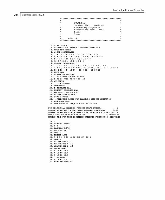
Part I - Application Examples
Example Problem 22 204
**************************************************** * * * STAAD.Pro * * Version 2007 Build 02 * * Proprietary Program of * * Research Engineers, Intl. * * Date= * * Time= * * * * USER ID: * **************************************************** 1. STAAD SPACE 2. *EXAMPLE FOR HARMONIC LOADING GENERATOR 3. UNIT KNS METER 4. JOINT COORDINATES 5. 1 0 0 0 ; 2 5 0 0 ; 3 5 0 5 ; 4 0 0 5 6. 5 0 7 0 ; 6 2.5 7 0 ; 7 5 7 0 ; 8 5 7 2.5 7. 9 5 7 5 ; 10 2.5 7 5 ; 11 0 7 5 8. 12 0 7 2.5 ; 13 2.5 7 2.5 9. MEMBER INCIDENCES 10. 1 1 5 ; 2 2 7 ; 3 3 9 ; 4 4 11 ; 5 5 6 ; 6 6 7 11. 7 7 8 ; 8 8 9 ; 9 9 10 ; 10 10 11 ; 11 11 12 ; 12 12 5 12. 13 6 13 ; 14 13 10 ; 15 8 13 ; 16 13 12 13. UNIT MMS 14. MEMBER PROPERTIES 15. 1 TO 4 PRIS YD 600 ZD 600 16. 5 TO 16 PRIS YD 450 ZD 450 17. SUPPORTS 18. 1 TO 4 PINNED 19. CONSTANTS 20. E CONCRETE ALL 21. DENSITY CONCRETE ALL 22. POISSON CONCRETE ALL 23. DEFINE TIME HISTORY 24. TYPE 1 FORCE 25. * FOLLOWING LINES FOR HARMONIC LOADING GENERATOR 26. FUNCTION SINE 27. AMPLITUDE 30 FREQUENCY 60 CYCLES 100 FOR SEQUENTIAL HARMONIC FORCING CURVE NUMBER= 1 NUMBER OF POINTS IN DIGITIZED HARMONIC FUNCTION= 1201 NUMBER OF POINTS PER QUARTER CYCLE OF HARMONIC FUNCTION= 3 FORCE STEP DELTA TIME PER POINT 1.38889E-03 ENDING TIME FOR THIS DIGITIZED HARMONIC FUNCTION 1.66667E+00 28. * 29. ARRIVAL TIMES 30. 0.0 31. DAMPING 0.075 32. UNIT METER 33. LOAD 1 34. MEMBER LOAD 35. 5 6 7 8 9 10 11 12 UNI GY -10.0 36. LOAD 2 37. SELFWEIGHT X 1.0 38. SELFWEIGHT Y 1.0 39. SELFWEIGHT Z 1.0 40. JOINT LOAD 41. 8 12 FX 15.0 42. 8 12 FY 15.0 43. 8 12 FZ 15.0 44. TIME LOAD 45. 8 12 FX 1 1 46. PERFORM ANALYSIS

Example Problem 22 205
P R O B L E M S T A T I S T I C S ----------------------------------- NUMBER OF JOINTS/MEMBER+ELEMENTS/SUPPORTS = 13/ 16/ 4 SOLVER USED IS THE IN-CORE ADVANCED SOLVER TOTAL PRIMARY LOAD CASES = 2, TOTAL DEGREES OF FREEDOM = 66 NUMBER OF MODES REQUESTED = 6 NUMBER OF EXISTING MASSES IN THE MODEL = 27 NUMBER OF MODES THAT WILL BE USED = 6 *** EIGENSOLUTION: ADVANCED METHOD *** CALCULATED FREQUENCIES FOR LOAD CASE 2 MODE FREQUENCY(CYCLES/SEC) PERIOD(SEC) 1 1.863 0.53664 2 1.864 0.53639 3 2.214 0.45158 4 18.318 0.05459 5 19.303 0.05181 6 23.509 0.04254 PARTICIPATION FACTORS MASS PARTICIPATION FACTORS IN PERCENT -------------------------------------- MODE X Y Z SUMM-X SUMM-Y SUMM-Z 1 100.00 0.00 0.00 99.996 0.000 0.000 2 0.00 0.00100.00 99.996 0.000 99.998 3 0.00 0.00 0.00 99.996 0.000 99.998 4 0.00 0.00 0.00 99.996 0.000 99.998 5 0.00 43.46 0.00 99.996 43.456 99.998 6 0.00 0.00 0.00 99.999 43.456 99.998 A C T U A L MODAL D A M P I N G USED IN ANALYSIS MODE DAMPING 1 0.0750 2 0.0750 3 0.0750 4 0.0750 5 0.0750 6 0.0750 TIME STEP USED IN TIME HISTORY ANALYSIS = 0.00139 SECONDS NUMBER OF MODES WHOSE CONTRIBUTION IS CONSIDERED = 6 TIME DURATION OF TIME HISTORY ANALYSIS = 1.665 SECONDS NUMBER OF TIME STEPS IN THE SOLUTION PROCESS = 1199 BASE SHEAR UNITS ARE -- KNS METE MAXIMUM BASE SHEAR X= -1.669199E+00 Y= -5.841255E-06 Z= -4.097819E-08 AT TIMES 0.127778 0.113889 0.118056 47. PRINT ANALYSIS RESULTS

Part I - Application Examples
Example Problem 22 206
JOINT DISPLACEMENT (CM RADIANS) STRUCTURE TYPE = SPACE ------------------ JOINT LOAD X-TRANS Y-TRANS Z-TRANS X-ROTAN Y-ROTAN Z-ROTAN 1 1 0.0000 0.0000 0.0000 -0.0001 0.0000 0.0001 2 0.0000 0.0000 0.0000 0.0000 0.0000 -0.0001 2 1 0.0000 0.0000 0.0000 -0.0001 0.0000 -0.0001 2 0.0000 0.0000 0.0000 0.0000 0.0000 -0.0001 3 1 0.0000 0.0000 0.0000 0.0001 0.0000 -0.0001 2 0.0000 0.0000 0.0000 0.0000 0.0000 -0.0001 4 1 0.0000 0.0000 0.0000 0.0001 0.0000 0.0001 2 0.0000 0.0000 0.0000 0.0000 0.0000 -0.0001 5 1 0.0001 -0.0045 0.0001 0.0002 0.0000 -0.0002 2 0.0408 0.0001 0.0000 0.0000 0.0000 0.0000 6 1 0.0000 -0.0472 0.0000 0.0001 0.0000 0.0000 2 0.0408 0.0000 0.0000 0.0000 0.0000 0.0000 7 1 -0.0001 -0.0045 0.0001 0.0002 0.0000 0.0002 2 0.0408 -0.0001 0.0000 0.0000 0.0000 0.0000 8 1 0.0000 -0.0472 0.0000 0.0000 0.0000 0.0001 2 0.0410 -0.0005 0.0000 0.0000 0.0000 0.0000 9 1 -0.0001 -0.0045 -0.0001 -0.0002 0.0000 0.0002 2 0.0408 -0.0001 0.0000 0.0000 0.0000 0.0000 10 1 0.0000 -0.0472 0.0000 -0.0001 0.0000 0.0000 2 0.0408 0.0000 0.0000 0.0000 0.0000 0.0000 11 1 0.0001 -0.0045 -0.0001 -0.0002 0.0000 -0.0002 2 0.0408 0.0001 0.0000 0.0000 0.0000 0.0000 12 1 0.0000 -0.0472 0.0000 0.0000 0.0000 -0.0001 2 0.0410 0.0005 0.0000 0.0000 0.0000 0.0000 13 1 0.0000 -0.0583 0.0000 0.0000 0.0000 0.0000 2 0.0410 0.0000 0.0000 0.0000 0.0000 0.0000 SUPPORT REACTIONS -UNIT KNS METE STRUCTURE TYPE = SPACE ----------------- JOINT LOAD FORCE-X FORCE-Y FORCE-Z MOM-X MOM-Y MOM Z 1 1 2.15 50.00 2.15 0.00 0.00 0.00 2 -0.42 -1.15 -0.02 0.00 0.00 0.00 2 1 -2.15 50.00 2.15 0.00 0.00 0.00 2 -0.42 1.15 0.02 0.00 0.00 0.00 3 1 -2.15 50.00 -2.15 0.00 0.00 0.00 2 -0.42 1.15 -0.02 0.00 0.00 0.00 4 1 2.15 50.00 -2.15 0.00 0.00 0.00 2 -0.42 -1.15 0.02 0.00 0.00 0.00 MEMBER END FORCES STRUCTURE TYPE = SPACE ----------------- ALL UNITS ARE -- KNS METE (LOCAL ) MEMBER LOAD JT AXIAL SHEAR-Y SHEAR-Z TORSION MOM-Y MOM-Z 1 1 1 50.00 -2.15 2.15 0.00 0.00 0.00 5 -50.00 2.15 -2.15 0.00 -15.04 -15.04 2 1 -1.15 0.42 -0.02 0.00 0.00 0.00 5 1.15 -0.42 0.02 0.00 0.12 2.92 2 1 2 50.00 2.15 2.15 0.00 0.00 0.00 7 -50.00 -2.15 -2.15 0.00 -15.04 15.04 2 2 1.15 0.42 0.02 0.00 0.00 0.00 7 -1.15 -0.42 -0.02 0.00 -0.12 2.92 3 1 3 50.00 2.15 -2.15 0.00 0.00 0.00 9 -50.00 -2.15 2.15 0.00 15.04 15.04 2 3 1.15 0.42 -0.02 0.00 0.00 0.00 9 -1.15 -0.42 0.02 0.00 0.12 2.92 4 1 4 50.00 -2.15 -2.15 0.00 0.00 0.00 11 -50.00 2.15 2.15 0.00 15.04 -15.04 2 4 -1.15 0.42 0.02 0.00 0.00 0.00 11 1.15 -0.42 -0.02 0.00 -0.12 2.92

Example Problem 22 207
MEMBER END FORCES STRUCTURE TYPE = SPACE ----------------- ALL UNITS ARE -- KNS METE (LOCAL ) MEMBER LOAD JT AXIAL SHEAR-Y SHEAR-Z TORSION MOM-Y MOM-Z 5 1 5 2.09 25.00 0.06 1.32 -0.07 16.36 6 -2.09 0.00 -0.06 -1.32 -0.07 14.89 2 5 -0.10 -1.05 -0.06 -0.02 0.08 -2.54 6 0.10 1.05 0.06 0.02 0.06 -0.08 6 1 6 2.09 0.00 -0.06 -1.32 0.07 -14.89 7 -2.09 25.00 0.06 1.32 0.07 -16.36 2 6 0.10 -1.05 -0.06 -0.02 0.06 -0.08 7 -0.10 1.05 0.06 0.02 0.08 -2.54 7 1 7 2.09 25.00 0.06 1.32 -0.07 16.36 8 -2.09 0.00 -0.06 -1.32 -0.07 14.89 2 7 -0.04 0.14 0.08 -0.38 -0.08 0.14 8 0.04 -0.14 -0.08 0.38 -0.12 0.21 8 1 8 2.09 0.00 -0.06 -1.32 0.07 -14.89 9 -2.09 25.00 0.06 1.32 0.07 -16.36 2 8 -0.04 -0.14 -0.08 0.38 0.12 -0.21 9 0.04 0.14 0.08 -0.38 0.08 -0.14 9 1 9 2.09 25.00 0.06 1.32 -0.07 16.36 10 -2.09 0.00 -0.06 -1.32 -0.07 14.89 2 9 0.10 1.05 0.06 0.02 -0.08 2.54 10 -0.10 -1.05 -0.06 -0.02 -0.06 0.08 10 1 10 2.09 0.00 -0.06 -1.32 0.07 -14.89 11 -2.09 25.00 0.06 1.32 0.07 -16.36 2 10 -0.10 1.05 0.06 0.02 -0.06 0.08 11 0.10 -1.05 -0.06 -0.02 -0.08 2.54 11 1 11 2.09 25.00 0.06 1.32 -0.07 16.36 12 -2.09 0.00 -0.06 -1.32 -0.07 14.89 2 11 0.04 -0.14 -0.08 0.38 0.08 -0.14 12 -0.04 0.14 0.08 -0.38 0.12 -0.21 12 1 12 2.09 0.00 -0.06 -1.32 0.07 -14.89 5 -2.09 25.00 0.06 1.32 0.07 -16.36 2 12 0.04 0.14 0.08 -0.38 -0.12 0.21 5 -0.04 -0.14 -0.08 0.38 -0.08 0.14 13 1 6 0.12 0.00 0.00 0.00 0.00 -2.64 13 -0.12 0.00 0.00 0.00 0.00 2.64 2 6 0.00 0.00 0.10 0.17 -0.12 0.00 13 0.00 0.00 -0.10 -0.17 -0.13 0.00 14 1 13 0.12 0.00 0.00 0.00 0.00 -2.64 10 -0.12 0.00 0.00 0.00 0.00 2.64 2 13 0.00 0.00 -0.10 -0.17 0.13 0.00 10 0.00 0.00 0.10 0.17 0.12 0.00 15 1 8 0.12 0.00 0.00 0.00 0.00 -2.64 13 -0.12 0.00 0.00 0.00 0.00 2.64 2 8 -0.03 0.24 0.00 0.00 0.00 0.76 13 0.03 -0.24 0.00 0.00 0.00 -0.17 16 1 13 0.12 0.00 0.00 0.00 0.00 -2.64 12 -0.12 0.00 0.00 0.00 0.00 2.64 2 13 0.03 0.24 0.00 0.00 0.00 -0.17 12 -0.03 -0.24 0.00 0.00 0.00 0.76 ************** END OF LATEST ANALYSIS RESULT **************

Part I - Application Examples
Example Problem 22 208
48. FINI *********** END OF THE STAAD.Pro RUN *********** **** DATE= TIME= **** ************************************************************ * For questions on STAAD.Pro, please contact * * Research Engineers Offices at the following locations * * * * Telephone Email * * USA: +1 (714)974-2500 [email protected] * * CANADA +1 (905)632-4771 [email protected] * * UK +44(1454)207-000 [email protected] * * FRANCE +33(0)1 64551084 [email protected] * * GERMANY +49/931/40468-71 [email protected] * * NORWAY +47 67 57 21 30 [email protected] * * SINGAPORE +65 6225-6158 [email protected] * * INDIA +91(033)4006-2021 [email protected] * * JAPAN +81(03)5952-6500 [email protected] * * CHINA +86(411)363-1983 [email protected] * * THAILAND +66(0)2645-1018/19 [email protected] * * * * North America [email protected] * * Europe [email protected] * * Asia [email protected] * ************************************************************

Example Problem 23 209
Example Problem No. 23
This example illustrates the usage of commands necessary to automatically generate spring supports for a slab on grade. The slab is subjected to pressure loading and analysis of the structure is performed. The numbers shown in the diagram below are the element numbers.

Part I - Application Examples
Example Problem 23 210
STAAD SPACE SLAB ON GRADE
Every STAAD input file has to begin with the word STAAD. The word SPACE signifies that the structure is a space frame and the geometry is defined through X, Y and Z axes. The remainder of the words form a title to identify this project.
UNIT METER KNS
The units for the data that follows are specified above.
JOINT COORDINATES 1 0.0 0.0 13.33 2 0.0 0.0 12.0 3 0.0 0.0 9.39 4 0.0 0.0 6.78 5 0.0 0.0 4.17 6 0.0 0.0 2.17 7 0.0 0.0 0.0 REPEAT ALL 3 2.83 0.0 0.0 REPEAT 3 2.67 0.0 0.0 REPEAT 5 2 0.0 0.0 REPEAT 3 2.67 0.0 0.0 REPEAT 3 2.83 0.0 0.0
For joints 1 through 7, the joint number followed by the X, Y and Z coordinates are specified above. The coordinates of these joints is used as a basis for generating 21 more joints by incrementing the X coordinate of each of these 7 joints by 2.83 metres, 3 times. REPEAT commands are used to generate the remaining joints of the structure. The results of the generation may be visually verified using the STAAD graphical viewing facilities.
ELEMENT INCIDENCES 1 1 8 9 2 TO 6 REPEAT 16 6 7
The incidences of element number 1 is defined and that data is used as a basis for generating the 2nd through the 6th element. The incidence pattern of the first 6 elements is then used to generate
Example Problem 23 211
the incidences of 96 (= 16 x 6) more elements using the REPEAT command.
UNIT CM ELEMENT PROPERTIES 1 TO 102 TH 14.0
The thickness of elements 1 to 102 is specified as 14 cms following the command ELEMENT PROPERTIES.
UNIT METER CONSTANTS E CONCRETE ALL POISSON CONCRETE ALL
The modulus of elasticity (E) and Poisson’s Ratio are specified following the command CONSTANTS. The built-in default value for concrete is used.
SUPPORTS 1 TO 126 ELASTIC MAT DIRECTION Y SUB 1570.
The above command is used to instruct STAAD to generate supports with springs which are effective in the global Y direction. These springs are located at nodes 1 to 126. The subgrade modulus of the soil is specified as 1570 KN/cu.m. The program will determine the area under the influence of each joint and multiply the influence area by the subgrade reaction to arrive at the spring stiffness for the "FY" degree of freedom at the joint. Additional information on this feature may be found in the STAAD Technical Reference Manual.
PRINT SUPP INFO
This command will enable us to obtain the details of the support conditions which were generated using the earlier commands.

Part I - Application Examples
Example Problem 23 212
LOAD 1 WEIGHT OF MAT & EARTH ELEMENT LOAD 1 TO 102 PR GY –74.2
The above data describe a static load case. A pressure load of 74.2 kN/sq.m. acting in the negative global Y direction is applied on all the 102 elements.
LOAD 2 'COLUMN LOAD-DL+LL' JOINT LOADS 1 2 FY -965. 8 9 FY -485. 5 FY -1373. 6 FY -2746. 22 23 FY -1824. 29 30 FY -912. 26 FY -2414. 27 FY -4828. 43 44 50 51 71 72 78 79 FY -1368. 47 54 82 FY -1175. 48 55 76 83 FY -2350. 92 93 FY -912. 99 100 FY -1824. 103 FY -2166. 104 FY -4333. 113 114 FY -485. 120 121 FY -965. 124 FY -1216. 125 FY -2431.
Load case 2 consists of several joint loads acting in the negative global Y direction.
LOADING COMBINATION 101 TOTAL LOAD 1 1. 2 1.
A load combination case, identified with load case number 101, is specified above. It instructs STAAD to factor loads 1 and 2 by a value of 1.0 and then algebraically add the results.

Example Problem 23 213
PERFORM ANALYSIS
The analysis is initiated using the above command.
UNIT CM LOAD LIST 101 PRINT JOINT DISPLACEMENTS LIST 33 56 PRINT ELEMENT STRESSES LIST 34 67
Joint displacements for joints 33 and 56, and element stresses for elements 34 and 67, for load case 101, is obtained with the help of the above commands.
FINISH
The STAAD run is terminated.

Part I - Application Examples
Example Problem 23 214
**************************************************** * * * STAAD.Pro * * Version 2007 Build 02 * * Proprietary Program of * * Research Engineers, Intl. * * Date= * * Time= * * * * USER ID: * **************************************************** 1. STAAD SPACE SLAB ON GRADE 2. UNIT METER KNS 3. JOINT COORDINATES 4. 1 0.0 0.0 13.33 5. 2 0.0 0.0 12.0 6. 3 0.0 0.0 9.39 7. 4 0.0 0.0 6.78 8. 5 0.0 0.0 4.17 9. 6 0.0 0.0 2.17 10. 7 0.0 0.0 0.0 11. REPEAT ALL 3 2.83 0.0 0.0 12. REPEAT 3 2.67 0.0 0.0 13. REPEAT 5 2 0.0 0.0 14. REPEAT 3 2.67 0.0 0.0 15. REPEAT 3 2.83 0.0 0.0 16. ELEMENT INCIDENCES 17. 1 1 8 9 2 TO 6 18. REPEAT 16 6 7 19. UNIT CM 20. ELEMENT PROPERTIES 21. 1 TO 102 TH 14.0 22. UNIT METER 23. CONSTANTS 24. E CONCRETE ALL 25. POISSON CONCRETE ALL 26. SUPPORTS 27. 1 TO 126 ELASTIC MAT DIRECTION Y SUB 1570. 28. PRINT SUPP INFO SUPPORT INFORMATION (1=FIXED, 0=RELEASED) ------------------- UNITS FOR SPRING CONSTANTS ARE KNS METE DEGREES JOINT FORCE-X/ FORCE-Y/ FORCE-Z/ MOM-X/ MOM-Y/ MOM-Z/ KFX KFY KFZ KMX KMY KMZ 1 1 0 1 0 1 0 0.0 1477.3 0.0 0.0 0.0 0.0 2 1 0 1 0 1 0 0.0 4376.5 0.0 0.0 0.0 0.0 3 1 0 1 0 1 0 0.0 5798.2 0.0 0.0 0.0 0.0 4 1 0 1 0 1 0 0.0 5798.2 0.0 0.0 0.0 0.0 5 1 0 1 0 1 0 0.0 5120.7 0.0 0.0 0.0 0.0 6 1 0 1 0 1 0 0.0 4631.9 0.0 0.0 0.0 0.0 7 1 0 1 0 1 0 0.0 2410.4 0.0 0.0 0.0 0.0 8 1 0 1 0 1 0 0.0 2954.7 0.0 0.0 0.0 0.0 9 1 0 1 0 1 0 0.0 8752.9 0.0 0.0 0.0 0.0 10 1 0 1 0 1 0 0.0 11596.5 0.0 0.0 0.0 0.0 11 1 0 1 0 1 0 0.0 11596.5 0.0 0.0 0.0 0.0 12 1 0 1 0 1 0 0.0 10241.3 0.0 0.0 0.0 0.0 13 1 0 1 0 1 0 0.0 9263.9 0.0 0.0 0.0 0.0

Example Problem 23 215
JOINT FORCE-X/ FORCE-Y/ FORCE-Z/ MOM-X/ MOM-Y/ MOM-Z/ KFX KFY KFZ KMX KMY KMZ 14 1 0 1 0 1 0 0.0 4820.8 0.0 0.0 0.0 0.0 15 1 0 1 0 1 0 0.0 2954.7 0.0 0.0 0.0 0.0 16 1 0 1 0 1 0 0.0 8752.9 0.0 0.0 0.0 0.0 17 1 0 1 0 1 0 0.0 11596.5 0.0 0.0 0.0 0.0 18 1 0 1 0 1 0 0.0 11596.5 0.0 0.0 0.0 0.0 19 1 0 1 0 1 0 0.0 10241.3 0.0 0.0 0.0 0.0 20 1 0 1 0 1 0 0.0 9263.9 0.0 0.0 0.0 0.0 21 1 0 1 0 1 0 0.0 4820.8 0.0 0.0 0.0 0.0 22 1 0 1 0 1 0 0.0 2871.1 0.0 0.0 0.0 0.0 23 1 0 1 0 1 0 0.0 8505.5 0.0 0.0 0.0 0.0 24 1 0 1 0 1 0 0.0 11268.7 0.0 0.0 0.0 0.0 25 1 0 1 0 1 0 0.0 11268.7 0.0 0.0 0.0 0.0 26 1 0 1 0 1 0 0.0 9951.8 0.0 0.0 0.0 0.0 27 1 0 1 0 1 0 0.0 9002.0 0.0 0.0 0.0 0.0 28 1 0 1 0 1 0 0.0 4684.5 0.0 0.0 0.0 0.0 29 1 0 1 0 1 0 0.0 2787.6 0.0 0.0 0.0 0.0 30 1 0 1 0 1 0 0.0 8258.0 0.0 0.0 0.0 0.0 31 1 0 1 0 1 0 0.0 10940.9 0.0 0.0 0.0 0.0 32 1 0 1 0 1 0 0.0 10940.9 0.0 0.0 0.0 0.0 33 1 0 1 0 1 0 0.0 9662.3 0.0 0.0 0.0 0.0 34 1 0 1 0 1 0 0.0 8740.1 0.0 0.0 0.0 0.0 35 1 0 1 0 1 0 0.0 4548.2 0.0 0.0 0.0 0.0 36 1 0 1 0 1 0 0.0 2787.6 0.0 0.0 0.0 0.0 37 1 0 1 0 1 0 0.0 8258.0 0.0 0.0 0.0 0.0 38 1 0 1 0 1 0 0.0 10940.9 0.0 0.0 0.0 0.0 39 1 0 1 0 1 0 0.0 10940.9 0.0 0.0 0.0 0.0 40 1 0 1 0 1 0 0.0 9662.3 0.0 0.0 0.0 0.0 41 1 0 1 0 1 0 0.0 8740.1 0.0 0.0 0.0 0.0 42 1 0 1 0 1 0 0.0 4548.2 0.0 0.0 0.0 0.0 43 1 0 1 0 1 0 0.0 2437.9 0.0 0.0 0.0 0.0 44 1 0 1 0 1 0 0.0 7221.9 0.0 0.0 0.0 0.0 45 1 0 1 0 1 0 0.0 9568.1 0.0 0.0 0.0 0.0 46 1 0 1 0 1 0 0.0 9568.1 0.0 0.0 0.0 0.0 47 1 0 1 0 1 0 0.0 8450.0 0.0 0.0 0.0 0.0 48 1 0 1 0 1 0 0.0 7643.5 0.0 0.0 0.0 0.0

Part I - Application Examples
Example Problem 23 216
JOINT FORCE-X/ FORCE-Y/ FORCE-Z/ MOM-X/ MOM-Y/ MOM-Z/ KFX KFY KFZ KMX KMY KMZ 49 1 0 1 0 1 0 0.0 3977.6 0.0 0.0 0.0 0.0 50 1 0 1 0 1 0 0.0 2088.1 0.0 0.0 0.0 0.0 51 1 0 1 0 1 0 0.0 6185.8 0.0 0.0 0.0 0.0 52 1 0 1 0 1 0 0.0 8195.4 0.0 0.0 0.0 0.0 53 1 0 1 0 1 0 0.0 8195.4 0.0 0.0 0.0 0.0 54 1 0 1 0 1 0 0.0 7237.7 0.0 0.0 0.0 0.0 55 1 0 1 0 1 0 0.0 6546.9 0.0 0.0 0.0 0.0 56 1 0 1 0 1 0 0.0 3406.9 0.0 0.0 0.0 0.0 57 1 0 1 0 1 0 0.0 2088.1 0.0 0.0 0.0 0.0 58 1 0 1 0 1 0 0.0 6185.8 0.0 0.0 0.0 0.0 59 1 0 1 0 1 0 0.0 8195.4 0.0 0.0 0.0 0.0 60 1 0 1 0 1 0 0.0 8195.4 0.0 0.0 0.0 0.0 61 1 0 1 0 1 0 0.0 7237.7 0.0 0.0 0.0 0.0 62 1 0 1 0 1 0 0.0 6546.9 0.0 0.0 0.0 0.0 63 1 0 1 0 1 0 0.0 3406.9 0.0 0.0 0.0 0.0 64 1 0 1 0 1 0 0.0 2088.1 0.0 0.0 0.0 0.0 65 1 0 1 0 1 0 0.0 6185.8 0.0 0.0 0.0 0.0 66 1 0 1 0 1 0 0.0 8195.4 0.0 0.0 0.0 0.0 67 1 0 1 0 1 0 0.0 8195.4 0.0 0.0 0.0 0.0 68 1 0 1 0 1 0 0.0 7237.7 0.0 0.0 0.0 0.0 69 1 0 1 0 1 0 0.0 6546.9 0.0 0.0 0.0 0.0 70 1 0 1 0 1 0 0.0 3406.9 0.0 0.0 0.0 0.0 71 1 0 1 0 1 0 0.0 2088.1 0.0 0.0 0.0 0.0 72 1 0 1 0 1 0 0.0 6185.8 0.0 0.0 0.0 0.0 73 1 0 1 0 1 0 0.0 8195.4 0.0 0.0 0.0 0.0 74 1 0 1 0 1 0 0.0 8195.4 0.0 0.0 0.0 0.0 75 1 0 1 0 1 0 0.0 7237.7 0.0 0.0 0.0 0.0 76 1 0 1 0 1 0 0.0 6546.9 0.0 0.0 0.0 0.0 77 1 0 1 0 1 0 0.0 3406.9 0.0 0.0 0.0 0.0 78 1 0 1 0 1 0 0.0 2437.9 0.0 0.0 0.0 0.0 79 1 0 1 0 1 0 0.0 7221.9 0.0 0.0 0.0 0.0 80 1 0 1 0 1 0 0.0 9568.1 0.0 0.0 0.0 0.0 81 1 0 1 0 1 0 0.0 9568.1 0.0 0.0 0.0 0.0 82 1 0 1 0 1 0 0.0 8450.0 0.0 0.0 0.0 0.0 83 1 0 1 0 1 0 0.0 7643.5 0.0 0.0 0.0 0.0

Example Problem 23 217
JOINT FORCE-X/ FORCE-Y/ FORCE-Z/ MOM-X/ MOM-Y/ MOM-Z/ KFX KFY KFZ KMX KMY KMZ 84 1 0 1 0 1 0 0.0 3977.6 0.0 0.0 0.0 0.0 85 1 0 1 0 1 0 0.0 2787.6 0.0 0.0 0.0 0.0 86 1 0 1 0 1 0 0.0 8258.0 0.0 0.0 0.0 0.0 87 1 0 1 0 1 0 0.0 10940.9 0.0 0.0 0.0 0.0 88 1 0 1 0 1 0 0.0 10940.9 0.0 0.0 0.0 0.0 89 1 0 1 0 1 0 0.0 9662.3 0.0 0.0 0.0 0.0 90 1 0 1 0 1 0 0.0 8740.1 0.0 0.0 0.0 0.0 91 1 0 1 0 1 0 0.0 4548.2 0.0 0.0 0.0 0.0 92 1 0 1 0 1 0 0.0 2787.6 0.0 0.0 0.0 0.0 93 1 0 1 0 1 0 0.0 8258.0 0.0 0.0 0.0 0.0 94 1 0 1 0 1 0 0.0 10940.9 0.0 0.0 0.0 0.0 95 1 0 1 0 1 0 0.0 10940.9 0.0 0.0 0.0 0.0 96 1 0 1 0 1 0 0.0 9662.3 0.0 0.0 0.0 0.0 97 1 0 1 0 1 0 0.0 8740.1 0.0 0.0 0.0 0.0 98 1 0 1 0 1 0 0.0 4548.2 0.0 0.0 0.0 0.0 99 1 0 1 0 1 0 0.0 2871.1 0.0 0.0 0.0 0.0 100 1 0 1 0 1 0 0.0 8505.5 0.0 0.0 0.0 0.0 101 1 0 1 0 1 0 0.0 11268.7 0.0 0.0 0.0 0.0 102 1 0 1 0 1 0 0.0 11268.7 0.0 0.0 0.0 0.0 103 1 0 1 0 1 0 0.0 9951.8 0.0 0.0 0.0 0.0 104 1 0 1 0 1 0 0.0 9002.0 0.0 0.0 0.0 0.0 105 1 0 1 0 1 0 0.0 4684.5 0.0 0.0 0.0 0.0 106 1 0 1 0 1 0 0.0 2954.7 0.0 0.0 0.0 0.0 107 1 0 1 0 1 0 0.0 8752.9 0.0 0.0 0.0 0.0 108 1 0 1 0 1 0 0.0 11596.5 0.0 0.0 0.0 0.0 109 1 0 1 0 1 0 0.0 11596.5 0.0 0.0 0.0 0.0 110 1 0 1 0 1 0 0.0 10241.3 0.0 0.0 0.0 0.0 111 1 0 1 0 1 0 0.0 9263.9 0.0 0.0 0.0 0.0 112 1 0 1 0 1 0 0.0 4820.8 0.0 0.0 0.0 0.0 113 1 0 1 0 1 0 0.0 2954.7 0.0 0.0 0.0 0.0 114 1 0 1 0 1 0 0.0 8752.9 0.0 0.0 0.0 0.0 115 1 0 1 0 1 0 0.0 11596.5 0.0 0.0 0.0 0.0 116 1 0 1 0 1 0 0.0 11596.5 0.0 0.0 0.0 0.0 117 1 0 1 0 1 0 0.0 10241.3 0.0 0.0 0.0 0.0 118 1 0 1 0 1 0 0.0 9263.9 0.0 0.0 0.0 0.0

Part I - Application Examples
Example Problem 23 218
JOINT FORCE-X/ FORCE-Y/ FORCE-Z/ MOM-X/ MOM-Y/ MOM-Z/ KFX KFY KFZ KMX KMY KMZ 119 1 0 1 0 1 0 0.0 4820.8 0.0 0.0 0.0 0.0 120 1 0 1 0 1 0 0.0 1477.3 0.0 0.0 0.0 0.0 121 1 0 1 0 1 0 0.0 4376.5 0.0 0.0 0.0 0.0 122 1 0 1 0 1 0 0.0 5798.2 0.0 0.0 0.0 0.0 123 1 0 1 0 1 0 0.0 5798.2 0.0 0.0 0.0 0.0 124 1 0 1 0 1 0 0.0 5120.7 0.0 0.0 0.0 0.0 125 1 0 1 0 1 0 0.0 4631.9 0.0 0.0 0.0 0.0 126 1 0 1 0 1 0 0.0 2410.4 0.0 0.0 0.0 0.0 ************ END OF DATA FROM INTERNAL STORAGE ************ 29. LOAD 1 WEIGHT OF MAT & EARTH 30. ELEMENT LOAD 31. 1 TO 102 PR GY -74.2 32. LOAD 2 'COLUMN LOAD-DL+LL' 33. JOINT LOADS 34. 1 2 FY -965. 35. 8 9 FY -485. 36. 5 FY -1373. 37. 6 FY -2746. 38. 22 23 FY -1824. 39. 29 30 FY -912. 40. 26 FY -2414. 41. 27 FY -4828. 42. 43 44 50 51 71 72 78 79 FY -1368. 43. 47 54 82 FY -1175. 44. 48 55 76 83 FY -2350. 45. 92 93 FY -912. 46. 99 100 FY -1824. 47. 103 FY -2166. 48. 104 FY -4333. 49. 113 114 FY -485. 50. 120 121 FY -965. 51. 124 FY -1216. 52. 125 FY -2431. 53. LOADING COMBINATION 101 TOTAL LOAD 54. 1 1. 2 1. 55. PERFORM ANALYSIS P R O B L E M S T A T I S T I C S ----------------------------------- NUMBER OF JOINTS/MEMBER+ELEMENTS/SUPPORTS = 126/ 102/ 126 SOLVER USED IS THE IN-CORE ADVANCED SOLVER TOTAL PRIMARY LOAD CASES = 2, TOTAL DEGREES OF FREEDOM = 378 56. UNIT CM 57. LOAD LIST 101 58. PRINT JOINT DISPLACEMENTS LIST 33 56

Example Problem 23 219
JOINT DISPLACEMENT (CM RADIANS) STRUCTURE TYPE = SPACE ------------------ JOINT LOAD X-TRANS Y-TRANS Z-TRANS X-ROTAN Y-ROTAN Z-ROTAN 33 101 0.0000 -10.5860 0.0000 -0.0256 0.0000 0.0543 56 101 0.0000 -12.2476 0.0000 0.0647 0.0000 0.0282 ************** END OF LATEST ANALYSIS RESULT ************** 59. PRINT ELEMENT STRESSES LIST 34 67 ELEMENT STRESSES FORCE,LENGTH UNITS= KNS CM ---------------- STRESS = FORCE/UNIT WIDTH/THICK, MOMENT = FORCE-LENGTH/UNIT WIDTH ELEMENT LOAD SQX SQY MX MY MXY VONT VONB SX SY SXY TRESCAT TRESCAB 34 101 -0.02 -0.03 2.43 18.01 40.71 2.22 2.22 0.00 0.00 0.00 2.54 2.54 TOP : SMAX= 1.58 SMIN= -0.96 TMAX= 1.27 ANGLE= -39.6 BOTT: SMAX= 0.96 SMIN= -1.58 TMAX= 1.27 ANGLE= -39.6 67 101 0.28 0.03 63.64 40.28 88.13 4.97 4.97 0.00 0.00 0.00 5.44 5.44 TOP : SMAX= 4.31 SMIN= -1.13 TMAX= 2.72 ANGLE= 41.2 BOTT: SMAX= 1.13 SMIN= -4.31 TMAX= 2.72 ANGLE= 41.2 **** MAXIMUM STRESSES AMONG SELECTED PLATES AND CASES **** MAXIMUM MINIMUM MAXIMUM MAXIMUM MAXIMUM PRINCIPAL PRINCIPAL SHEAR VONMISES TRESCA STRESS STRESS STRESS STRESS STRESS 4.312085E+00 -4.312085E+00 2.721572E+00 4.974997E+00 5.443144E+00 PLATE NO. 67 67 67 67 67 CASE NO. 101 101 101 101 101 ********************END OF ELEMENT FORCES******************** 60. FINISH *********** END OF THE STAAD.Pro RUN *********** **** DATE= TIME= **** ************************************************************ * For questions on STAAD.Pro, please contact * * Research Engineers Offices at the following locations * * * * Telephone Email * * USA: +1 (714)974-2500 [email protected] * * CANADA +1 (905)632-4771 [email protected] * * UK +44(1454)207-000 [email protected] * * FRANCE +33(0)1 64551084 [email protected] * * GERMANY +49/931/40468-71 [email protected] * * NORWAY +47 67 57 21 30 [email protected] * * SINGAPORE +65 6225-6158 [email protected] * * INDIA +91(033)4006-2021 [email protected] * * JAPAN +81(03)5952-6500 [email protected] * * CHINA +86(411)363-1983 [email protected] * * THAILAND +66(0)2645-1018/19 [email protected] * * * * North America [email protected] * * Europe [email protected] * * Asia [email protected] * ************************************************************

Part I - Application Examples
Example Problem 23 220
NOTES

Example Problem 24 221
Example Problem No. 24
This is an example of the analysis of a structure modelled using “SOLID” finite elements. This example also illustrates the method for applying an “enforced” displacement on the structure.

Part I - Application Examples
Example Problem 24 222
STAAD SPACE *EXAMPLE PROBLEM USING SOLID ELEMENTS
Every STAAD input file has to begin with the word STAAD. The word SPACE signifies that the structure is a space frame and the geometry is defined through X, Y and Z axes. The comment line which begins with an asterisk is an optional title to identify this project.
UNIT KNS MET
The units for the data that follows are specified above.
JOINT COORDINATES 1 0.0 0.0 2.0 4 0.0 3.0 2.0 5 1.0 0.0 2.0 8 1.0 3.0 2.0 9 2.0 0.0 2.0 12 2.0 3.0 2.0 21 0.0 0.0 1.0 24 0.0 3.0 1.0 25 1.0 0.0 1.0 28 1.0 3.0 1.0 29 2.0 0.0 1.0 32 2.0 3.0 1.0 41 0.0 0.0 0.0 44 0.0 3.0 0.0 45 1.0 0.0 0.0 48 1.0 3.0 0.0 49 2.0 0.0 0.0 52 2.0 3.0 0.0
The joint number followed by the X, Y and Z coordinates are specified above. The coordinates of some of those nodes are generated utilizing the fact that they are equally spaced between the extremities.
ELEMENT INCIDENCES SOLID 1 1 5 6 2 21 25 26 22 TO 3 4 21 25 26 22 41 45 46 42 TO 6 1 1 7 5 9 10 6 25 29 30 26 TO 9 1 1 10 25 29 30 26 45 49 50 46 TO 12 1 1
The incidences of solid elements are defined above. The word SOLID is used to signify that these are 8-noded solid elements as opposed to 3-noded or 4-noded plate elements. Each line contains the data for generating 3 elements. For example, element number 1 is first defined by all of its 8 nodes. Then, increments of 1 to the

Example Problem 24 223
joint number and 1 to the element number (the defaults) are used for generating incidences for elements 2 and 3. Similarly, incidences of elements 4, 7 and 10 are defined while those of 5, 6, 8, 9, 11 and 12 are generated.
CONSTANTS E 2.1E7 ALL POIS 0.25 ALL DENSITY 7.5 ALL
Following the command CONSTANTS above, the material constants such as E (Modulus of Elasticity), Poisson's Ratio, and Density are specified.
PRINT ELEMENT INFO SOLID LIST 1 TO 5
This command will enable us to obtain, in a tabular form, the details of the incidences and material property values of elements 1 to 5.
SUPPORTS 1 5 21 25 29 41 45 49 PINNED 9 ENFORCED
The above lines contain the data for supports for the model. The ENFORCED support condition is used to declare a point at which an enforced displacement load is applied later (see load case 3).
LOAD 1 SELF Y -1.0 JOINT LOAD 28 FY -1000.0
The above data describe a static load case. It consists of selfweight loading and a joint load, both in the negative global Y direction.
LOAD 2 JOINT LOADS 2 TO 4 22 TO 24 42 TO 44 FX 100.0

Part I - Application Examples
Example Problem 24 224
Load case 2 consists of several joint loads acting in the positive global X direction.
LOAD 3 SUPPORT DISPLACEMENT 9 FX 0.0011
Load case 3 consists of an enforced displacement along the global X direction at node 9. The displacement in the other enforced support degrees of freedom will default to zero.
UNIT POUND FEET LOAD 4 ELEMENT LOAD SOLIDS 3 6 9 12 FACE 4 PRE GY -500.0
In Load case 4, a pressure load of 500 pounds/sq.ft is applied on Face # 4 of solid elements 3, 6, 9 and 12. Face 4 is defined as shown in the following table :
SURFACE JOINTS FACE NUMBER f1 f2 f3 f4
1 front Jt 1 Jt 4 Jt 3 Jt 2 2 bottom Jt 1 Jt 2 Jt 6 Jt 5 3 left Jt 1 Jt 5 Jt 8 Jt 4 4 top Jt 4 Jt 8 Jt 7 Jt 3 5 right Jt 2 Jt 3 Jt 7 Jt 6 6 back Jt 5 Jt 6 Jt 7 Jt 8 The above table, and other details of this type of loading can be found in section 5.32.3.2 of the STAAD.Pro 2003 Technical Reference manual.
UNIT KNS MMS LOAD 5 REPEAT LOAD 1 1.0 2 1.0 3 1.0 4 1.0

Example Problem 24 225
Load case 5 illustrates the technique employed to instruct STAAD to create a load case which consists of data to be assembled from other load cases already specified earlier. We would like the program to analyze the structure for loads from cases 1 through 4 acting simultaneously. In other words, the above instruction is the same as the following:
LOAD 5 SELF Y -1.0 JOINT LOAD 28 FY -1000.0 2 TO 4 22 TO 24 42 TO 44 FX 100.0 SUPPORT DISPLACEMENT 9 FX .0011 ELEMENT LOAD SOLIDS 3 6 9 12 FACE 4 PRE GY -500.0
LOAD COMB 10 1 1.0 2 1.0
Load case 10 is a combination load case, which combines the effects of cases 1 & 2. While the syntax of this might look very similar to that of the REPEAT LOAD case shown in case 5, there is a fundamental difference. In a REPEAT LOAD case, the program computes the displacements by multiplying the inverted stiffness matrix by the load vector built for the REPEAT LOAD case. But in solving load combination cases, the program merely calculates the end results (displacements, forces, reactions) by gathering up the corresponding values from the individual components of the combination case, factoring them, and then algebraically summing them up. This difference in approach is quite important in that non-linear problems such as PDELTA ANALYSIS, MEMBER TENSION and MEMBER COMPRESSION situations, changes in support conditions etc. should be handled using REPEAT LOAD cases, not load combination cases.
PERFORM ANALYSIS PRINT STATICS CHECK
A static equilibrium report, consisting of total applied loading and total support reactions from each primary load case is requested along with the instructions to carry out a linear static analysis.

Part I - Application Examples
Example Problem 24 226
PRINT JOINT DISPLACEMENTS LIST 8 9
Global displacements at nodes 8 and 9 are obtained using the above command.
UNIT KNS METER PRINT SUPPORT REACTIONS
Reactions at the supports are obtained using the above command.
UNIT NEWTON MMS PRINT ELEMENT JOINT STRESS SOLID LIST 4 6
This command requests the program to provide the element stress results at the nodes of elements 4 and 6. The results will be printed for all the load cases. The word SOLID is used to signify that these are solid elements as opposed to plate or shell elements.
FINISH
The STAAD run is terminated.

Example Problem 24 227
**************************************************** * * * STAAD.Pro * * Version 2007 Build 02 * * Proprietary Program of * * Research Engineers, Intl. * * Date= * * Time= * * * * USER ID: * **************************************************** 1. STAAD SPACE 2. *EXAMPLE PROBLEM USING SOLID ELEMENTS 3. UNIT KNS MET 4. JOINT COORDINATES 5. 1 0.0 0.0 2.0 4 0.0 3.0 2.0 6. 5 1.0 0.0 2.0 8 1.0 3.0 2.0 7. 9 2.0 0.0 2.0 12 2.0 3.0 2.0 8. 21 0.0 0.0 1.0 24 0.0 3.0 1.0 9. 25 1.0 0.0 1.0 28 1.0 3.0 1.0 10. 29 2.0 0.0 1.0 32 2.0 3.0 1.0 11. 41 0.0 0.0 0.0 44 0.0 3.0 0.0 12. 45 1.0 0.0 0.0 48 1.0 3.0 0.0 13. 49 2.0 0.0 0.0 52 2.0 3.0 0.0 14. ELEMENT INCIDENCES SOLID 15. 1 1 5 6 2 21 25 26 22 TO 3 16. 4 21 25 26 22 41 45 46 42 TO 6 1 1 17. 7 5 9 10 6 25 29 30 26 TO 9 1 1 18. 10 25 29 30 26 45 49 50 46 TO 12 1 1 19. CONSTANTS 20. E 2.1E7 ALL 21. POIS 0.25 ALL 22. DENSITY 7.5 ALL 23. PRINT ELEMENT INFO SOLID LIST 1 TO 5 ELEMENT NODE-1 NODE-2 NODE-3 NODE-4 NODE-5 NODE-6 NODE-7 NODE-8 1 1 5 6 2 21 25 26 22 2 2 6 7 3 22 26 27 23 3 3 7 8 4 23 27 28 24 4 21 25 26 22 41 45 46 42 5 22 26 27 23 42 46 47 43 MATERIAL PROPERTIES. -------------------- ALL UNITS ARE - KNS MET ELEMENT YOUNG'S MODULUS MODULUS OF RIGIDITY DENSITY ALPHA 1 2.1000002E+07 0.0000000E+00 7.5000E+00 0.0000E+00 2 2.1000002E+07 0.0000000E+00 7.5000E+00 0.0000E+00 3 2.1000002E+07 0.0000000E+00 7.5000E+00 0.0000E+00 4 2.1000002E+07 0.0000000E+00 7.5000E+00 0.0000E+00 5 2.1000002E+07 0.0000000E+00 7.5000E+00 0.0000E+00 24. SUPPORTS 25. 1 5 21 25 29 41 45 49 PINNED 26. 9 ENFORCED 27. LOAD 1 28. SELF Y -1.0 29. JOINT LOAD 30. 28 FY -1000.0 31. LOAD 2 32. JOINT LOADS 33. 2 TO 4 22 TO 24 42 TO 44 FX 100.0 34. LOAD 3 35. SUPPORT DISPLACEMENT 36. 9 FX 0.0011

Part I - Application Examples
Example Problem 24 228
37. UNIT POUND FEET 38. LOAD 4 39. ELEMENT LOAD SOLIDS 40. 3 6 9 12 FACE 4 PRE GY -500.0 41. UNIT KNS MMS 42. LOAD 5 43. REPEAT LOAD 44. 1 1.0 2 1.0 3 1.0 4 1.0 45. LOAD COMB 10 46. 1 1.0 2 1.0 47. PERFORM ANALYSIS PRINT STATICS CHECK P R O B L E M S T A T I S T I C S ----------------------------------- NUMBER OF JOINTS/MEMBER+ELEMENTS/SUPPORTS = 36/ 12/ 9 SOLVER USED IS THE IN-CORE ADVANCED SOLVER TOTAL PRIMARY LOAD CASES = 5, TOTAL DEGREES OF FREEDOM = 87 ZERO STIFFNESS IN DIRECTION 4 AT JOINT 9 EQN.NO. 22 LOADS APPLIED OR DISTRIBUTED HERE FROM ELEMENTS WILL BE IGNORED. THIS MAY BE DUE TO ALL MEMBERS AT THIS JOINT BEING RELEASED OR EFFECTIVELY RELEASED IN THIS DIRECTION. ZERO STIFFNESS IN DIRECTION 5 AT JOINT 9 EQN.NO. 23 ZERO STIFFNESS IN DIRECTION 6 AT JOINT 9 EQN.NO. 24 Note - Some or all of the rotational zero stiffness warnings may be due to solid elements in the model. Solids do not have rotational stiffnesses at nodes. STATIC LOAD/REACTION/EQUILIBRIUM SUMMARY FOR CASE NO. 1 ***TOTAL APPLIED LOAD ( KNS MMS ) SUMMARY (LOADING 1 ) SUMMATION FORCE-X = 0.00 SUMMATION FORCE-Y = -1090.00 SUMMATION FORCE-Z = 0.00 SUMMATION OF MOMENTS AROUND THE ORIGIN- MX= 1089999.98 MY= 0.00 MZ= -1089999.98 ***TOTAL REACTION LOAD( KNS MMS ) SUMMARY (LOADING 1 ) SUMMATION FORCE-X = 0.00 SUMMATION FORCE-Y = 1090.00 SUMMATION FORCE-Z = 0.00 SUMMATION OF MOMENTS AROUND THE ORIGIN- MX= -1089999.98 MY= 0.00 MZ= 1089999.98 MAXIMUM DISPLACEMENTS ( CM /RADIANS) (LOADING 1) MAXIMUMS AT NODE X = -1.12983E-03 23 Y = -1.01204E-02 28 Z = 1.12983E-03 7 RX= 0.00000E+00 0 RY= 0.00000E+00 0 RZ= 0.00000E+00 0 STATIC LOAD/REACTION/EQUILIBRIUM SUMMARY FOR CASE NO. 2 ***TOTAL APPLIED LOAD ( KNS MMS ) SUMMARY (LOADING 2 ) SUMMATION FORCE-X = 900.00 SUMMATION FORCE-Y = 0.00 SUMMATION FORCE-Z = 0.00 SUMMATION OF MOMENTS AROUND THE ORIGIN- MX= 0.00 MY= 899999.97 MZ= -1799999.93
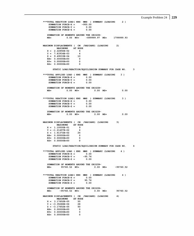
Example Problem 24 229
***TOTAL REACTION LOAD( KNS MMS ) SUMMARY (LOADING 2 ) SUMMATION FORCE-X = -900.00 SUMMATION FORCE-Y = 0.00 SUMMATION FORCE-Z = 0.00 SUMMATION OF MOMENTS AROUND THE ORIGIN- MX= 0.00 MY= -899999.97 MZ= 1799999.93 MAXIMUM DISPLACEMENTS ( CM /RADIANS) (LOADING 2) MAXIMUMS AT NODE X = 2.22892E-02 4 Y = 7.83934E-03 4 Z = 9.49033E-04 10 RX= 0.00000E+00 0 RY= 0.00000E+00 0 RZ= 0.00000E+00 0 STATIC LOAD/REACTION/EQUILIBRIUM SUMMARY FOR CASE NO. 3 ***TOTAL APPLIED LOAD ( KNS MMS ) SUMMARY (LOADING 3 ) SUMMATION FORCE-X = 0.00 SUMMATION FORCE-Y = 0.00 SUMMATION FORCE-Z = 0.00 SUMMATION OF MOMENTS AROUND THE ORIGIN- MX= 0.00 MY= 0.00 MZ= 0.00 ***TOTAL REACTION LOAD( KNS MMS ) SUMMARY (LOADING 3 ) SUMMATION FORCE-X = 0.00 SUMMATION FORCE-Y = 0.00 SUMMATION FORCE-Z = 0.00 SUMMATION OF MOMENTS AROUND THE ORIGIN- MX= 0.00 MY= 0.00 MZ= 0.00 MAXIMUM DISPLACEMENTS ( CM /RADIANS) (LOADING 3) MAXIMUMS AT NODE X = 1.10000E-01 9 Y = -1.21497E-02 6 Z = 1.61372E-02 24 RX= 0.00000E+00 0 RY= 0.00000E+00 0 RZ= 0.00000E+00 0 STATIC LOAD/REACTION/EQUILIBRIUM SUMMARY FOR CASE NO. 4 ***TOTAL APPLIED LOAD ( KNS MMS ) SUMMARY (LOADING 4 ) SUMMATION FORCE-X = 0.00 SUMMATION FORCE-Y = -95.76 SUMMATION FORCE-Z = 0.00 SUMMATION OF MOMENTS AROUND THE ORIGIN- MX= 95760.52 MY= 0.00 MZ= -95760.52 ***TOTAL REACTION LOAD( KNS MMS ) SUMMARY (LOADING 4 ) SUMMATION FORCE-X = 0.00 SUMMATION FORCE-Y = 95.76 SUMMATION FORCE-Z = 0.00 SUMMATION OF MOMENTS AROUND THE ORIGIN- MX= -95760.52 MY= 0.00 MZ= 95760.52 MAXIMUM DISPLACEMENTS ( CM /RADIANS) (LOADING 4) MAXIMUMS AT NODE X = 3.17652E-05 50 Y = -3.35288E-04 28 Z = -3.17652E-05 50 RX= 0.00000E+00 0 RY= 0.00000E+00 0 RZ= 0.00000E+00 0

Part I - Application Examples
Example Problem 24 230
STATIC LOAD/REACTION/EQUILIBRIUM SUMMARY FOR CASE NO. 5 ***TOTAL APPLIED LOAD ( KNS MMS ) SUMMARY (LOADING 5 ) SUMMATION FORCE-X = 900.00 SUMMATION FORCE-Y = -1185.76 SUMMATION FORCE-Z = 0.00 SUMMATION OF MOMENTS AROUND THE ORIGIN- MX= 1185760.50 MY= 899999.97 MZ= -2985760.43 ***TOTAL REACTION LOAD( KNS MMS ) SUMMARY (LOADING 5 ) SUMMATION FORCE-X = -900.00 SUMMATION FORCE-Y = 1185.76 SUMMATION FORCE-Z = 0.00 SUMMATION OF MOMENTS AROUND THE ORIGIN- MX= -1185760.50 MY= -899999.97 MZ= 2985760.43 MAXIMUM DISPLACEMENTS ( CM /RADIANS) (LOADING 5) MAXIMUMS AT NODE X = 1.10000E-01 9 Y = -1.66887E-02 12 Z = 1.62734E-02 4 RX= 0.00000E+00 0 RY= 0.00000E+00 0 RZ= 0.00000E+00 0 ************ END OF DATA FROM INTERNAL STORAGE ************ 48. PRINT JOINT DISPLACEMENTS LIST 8 9 JOINT DISPLACEMENT (CM RADIANS) STRUCTURE TYPE = SPACE ------------------ JOINT LOAD X-TRANS Y-TRANS Z-TRANS X-ROTAN Y-ROTAN Z-ROTAN 8 1 0.0000 -0.0010 -0.0008 0.0000 0.0000 0.0000 2 0.0200 0.0001 0.0000 0.0000 0.0000 0.0000 3 0.0193 -0.0049 0.0089 0.0000 0.0000 0.0000 4 0.0000 -0.0003 0.0000 0.0000 0.0000 0.0000 5 0.0393 -0.0062 0.0081 0.0000 0.0000 0.0000 10 0.0200 -0.0009 -0.0009 0.0000 0.0000 0.0000 9 1 0.0000 0.0000 0.0000 0.0000 0.0000 0.0000 2 0.0000 0.0000 0.0000 0.0000 0.0000 0.0000 3 0.1100 0.0000 0.0000 0.0000 0.0000 0.0000 4 0.0000 0.0000 0.0000 0.0000 0.0000 0.0000 5 0.1100 0.0000 0.0000 0.0000 0.0000 0.0000 10 0.0000 0.0000 0.0000 0.0000 0.0000 0.0000 ************** END OF LATEST ANALYSIS RESULT ************** 49. UNIT KNS METER 50. PRINT SUPPORT REACTIONS SUPPORT REACTIONS -UNIT KNS METE STRUCTURE TYPE = SPACE ----------------- JOINT LOAD FORCE-X FORCE-Y FORCE-Z MOM-X MOM-Y MOM Z 1 1 16.05 74.37 -16.05 0.00 0.00 0.00 2 -72.24 -232.67 42.18 0.00 0.00 0.00 3 -202.27 -30.20 -119.24 0.00 0.00 0.00 4 1.52 6.63 -1.52 0.00 0.00 0.00 5 -256.94 -181.87 -94.63 0.00 0.00 0.00 10 -56.19 -158.30 26.13 0.00 0.00 0.00 5 1 0.00 135.25 -31.85 0.00 0.00 0.00 2 -62.32 11.42 -0.05 0.00 0.00 0.00 3 -1641.00 743.48 -228.79 0.00 0.00 0.00 4 0.00 11.97 -2.98 0.00 0.00 0.00 5 -1703.32 902.13 -263.67 0.00 0.00 0.00 10 -62.32 146.68 -31.90 0.00 0.00 0.00

Example Problem 24 231
JOINT LOAD FORCE-X FORCE-Y FORCE-Z MOM-X MOM-Y MOM Z 21 1 31.85 135.25 0.00 0.00 0.00 0.00 2 -159.92 -450.84 0.00 0.00 0.00 0.00 3 -334.17 -292.36 -187.70 0.00 0.00 0.00 4 2.98 11.97 0.00 0.00 0.00 0.00 5 -459.26 -595.97 -187.70 0.00 0.00 0.00 10 -128.07 -315.58 0.00 0.00 0.00 0.00 25 1 0.00 251.52 0.00 0.00 0.00 0.00 2 -138.00 9.51 0.00 0.00 0.00 0.00 3 -1919.80 524.87 -1097.52 0.00 0.00 0.00 4 0.00 21.34 0.00 0.00 0.00 0.00 5 -2057.79 807.24 -1097.52 0.00 0.00 0.00 10 -138.00 261.03 0.00 0.00 0.00 0.00 29 1 -31.85 135.25 0.00 0.00 0.00 0.00 2 -170.27 431.34 0.00 0.00 0.00 0.00 3 390.27 51.20 384.26 0.00 0.00 0.00 4 -2.98 11.97 0.00 0.00 0.00 0.00 5 185.18 629.77 384.26 0.00 0.00 0.00 10 -202.12 566.59 0.00 0.00 0.00 0.00 41 1 16.05 74.37 16.05 0.00 0.00 0.00 2 -72.24 -232.67 -42.18 0.00 0.00 0.00 3 -89.12 -273.99 -159.85 0.00 0.00 0.00 4 1.52 6.63 1.52 0.00 0.00 0.00 5 -143.78 -425.66 -184.46 0.00 0.00 0.00 10 -56.19 -158.30 -26.13 0.00 0.00 0.00 45 1 0.00 135.25 31.85 0.00 0.00 0.00 2 -62.32 11.42 0.05 0.00 0.00 0.00 3 -43.04 -75.25 -23.76 0.00 0.00 0.00 4 0.00 11.97 2.98 0.00 0.00 0.00 5 -105.36 83.40 11.12 0.00 0.00 0.00 10 -62.32 146.68 31.90 0.00 0.00 0.00 49 1 -16.05 74.37 16.05 0.00 0.00 0.00 2 -81.35 226.24 45.03 0.00 0.00 0.00 3 -77.83 207.38 119.24 0.00 0.00 0.00 4 -1.52 6.63 1.52 0.00 0.00 0.00 5 -176.75 514.62 181.84 0.00 0.00 0.00 10 -97.40 300.61 61.08 0.00 0.00 0.00 9 1 -16.05 74.37 -16.05 0.00 0.00 0.00 2 -81.35 226.24 -45.03 0.00 0.00 0.00 3 3916.95 -855.13 1313.37 0.00 0.00 0.00 4 -1.52 6.63 -1.52 0.00 0.00 0.00 5 3818.02 -547.89 1250.77 0.00 0.00 0.00 10 -97.40 300.61 -61.08 0.00 0.00 0.00 ************** END OF LATEST ANALYSIS RESULT ************** 51. UNIT NEWTON MMS 52. PRINT ELEMENT JOINT STRESS SOLID LIST 4 6 ELEMENT STRESSES UNITS= NEWTMMS ------------------------------------------------------------------------------- NODE/ NORMAL STRESSES SHEAR STRESSES ELEMENT LOAD CENTER SXX SYY SZZ SXY SYZ SZX ------------------------------------------------------------------------------- 4 1 21 -0.088 -0.280 -0.098 0.001 -0.003 0.000 4 1 25 -0.076 -0.204 -0.076 -0.003 -0.003 0.005 4 1 26 -0.008 -0.214 -0.008 0.004 0.004 0.005 4 1 22 -0.011 -0.280 -0.002 0.009 -0.011 0.009 4 1 41 -0.095 -0.311 -0.095 -0.008 -0.008 -0.005 4 1 45 -0.098 -0.280 -0.088 -0.003 0.001 0.000 4 1 46 -0.002 -0.280 -0.011 -0.011 0.009 0.009 4 1 42 0.011 -0.301 0.011 -0.016 -0.016 0.014 4 1 CENTER -0.046 -0.269 -0.046 -0.003 -0.003 0.005 S1= -0.041 S2= -0.051 S3= -0.269 SE= 0.223 DC= 0.707 -0.021 0.707 -0.707 0.000 0.707

Part I - Application Examples
Example Problem 24 232
ELEMENT STRESSES UNITS= NEWTMMS ------------------------------------------------------------------------------- NODE/ NORMAL STRESSES SHEAR STRESSES ELEMENT LOAD CENTER SXX SYY SZZ SXY SYZ SZX ------------------------------------------------------------------------------- 4 2 21 0.176 1.021 0.284 0.217 0.014 0.005 4 2 25 0.154 -0.006 0.022 0.251 0.014 -0.029 4 2 26 -0.028 0.053 -0.015 0.253 0.016 -0.002 4 2 22 -0.054 1.031 0.103 0.219 0.012 -0.036 4 2 41 0.189 1.034 0.321 0.258 0.038 0.029 4 2 45 0.162 -0.006 0.054 0.223 -0.010 -0.005 4 2 46 -0.225 -0.016 -0.051 0.221 -0.008 -0.026 4 2 42 -0.247 0.976 0.071 0.255 0.036 -0.060 4 2 CENTER 0.016 0.511 0.099 0.237 0.014 -0.015 S1= 0.606 S2= 0.101 S3= -0.082 SE= 0.617 DC= 0.372 0.928 0.014 -0.106 0.027 0.994 4 3 21 0.090 0.518 0.188 0.499 0.506 0.040 4 3 25 -0.089 -0.574 -0.129 0.661 0.143 -0.123 4 3 26 0.525 -0.328 0.365 0.565 0.047 0.327 4 3 22 0.538 0.597 0.183 0.403 0.602 0.165 4 3 41 0.215 0.951 0.255 0.011 0.589 0.123 4 3 45 0.228 0.435 0.129 -0.152 0.060 -0.040 4 3 46 -0.133 0.355 0.298 -0.056 -0.036 0.244 4 3 42 -0.313 0.705 -0.076 0.107 0.685 0.082 4 3 CENTER 0.132 0.332 0.152 0.255 0.324 0.102 S1= 0.703 S2= 0.041 S3= -0.128 SE= 0.760 DC= 0.425 0.744 0.516 0.809 -0.055 -0.586 4 4 21 -0.008 -0.024 -0.008 -0.001 -0.001 0.000 4 4 25 -0.008 -0.022 -0.008 -0.001 -0.001 0.000 4 4 26 0.001 -0.022 0.001 -0.001 -0.001 0.000 4 4 22 0.001 -0.024 0.001 -0.001 -0.001 0.000 4 4 41 -0.008 -0.026 -0.008 -0.001 -0.001 0.000 4 4 45 -0.008 -0.024 -0.008 -0.001 -0.001 0.000 4 4 46 0.001 -0.024 0.001 -0.001 -0.001 0.000 4 4 42 0.001 -0.026 0.001 -0.001 -0.001 0.000 4 4 CENTER -0.004 -0.024 -0.004 -0.001 -0.001 0.000 S1= -0.003 S2= -0.004 S3= -0.024 SE= 0.021 DC= 0.705 -0.070 0.705 -0.707 0.000 0.707 4 5 21 0.170 1.235 0.366 0.716 0.515 0.045 4 5 25 -0.019 -0.806 -0.191 0.908 0.153 -0.147 4 5 26 0.490 -0.512 0.343 0.822 0.066 0.330 4 5 22 0.474 1.324 0.285 0.630 0.602 0.138 4 5 41 0.300 1.649 0.472 0.259 0.618 0.147 4 5 45 0.283 0.125 0.087 0.067 0.050 -0.045 4 5 46 -0.360 0.035 0.238 0.153 -0.036 0.228 4 5 42 -0.548 1.354 0.007 0.345 0.704 0.036 4 5 CENTER 0.099 0.551 0.201 0.487 0.334 0.092 S1= 1.000 S2= 0.093 S3= -0.243 SE= 1.114 DC= 0.469 0.795 0.386 -0.452 -0.160 0.878 4 10 21 0.088 0.741 0.186 0.218 0.011 0.005 4 10 25 0.078 -0.210 -0.054 0.247 0.011 -0.024 4 10 26 -0.036 -0.161 -0.022 0.257 0.020 0.003 4 10 22 -0.065 0.751 0.102 0.228 0.001 -0.027 4 10 41 0.093 0.724 0.225 0.249 0.030 0.024 4 10 45 0.064 -0.286 -0.034 0.220 -0.009 -0.005 4 10 46 -0.227 -0.296 -0.062 0.210 0.001 -0.016 4 10 42 -0.236 0.675 0.082 0.240 0.020 -0.046 4 10 CENTER -0.030 0.242 0.053 0.234 0.011 -0.011 S1= 0.376 S2= 0.054 S3= -0.165 SE= 0.472 DC= 0.498 0.867 0.012 -0.064 0.023 0.998

Example Problem 24 233
ELEMENT STRESSES UNITS= NEWTMMS ------------------------------------------------------------------------------- NODE/ NORMAL STRESSES SHEAR STRESSES ELEMENT LOAD CENTER SXX SYY SZZ SXY SYZ SZX ------------------------------------------------------------------------------- 6 1 23 0.317 0.428 0.402 -0.043 -0.126 -0.060 6 1 27 -0.082 -1.708 -0.082 -0.098 -0.098 -0.005 6 1 28 -0.670 -1.819 -0.670 -0.552 -0.552 -0.005 6 1 24 -0.160 0.428 0.146 -0.497 0.329 0.051 6 1 43 -0.108 -0.163 -0.108 -0.181 -0.181 -0.115 6 1 47 0.402 0.428 0.317 -0.126 -0.043 -0.060 6 1 48 0.146 0.428 -0.160 0.329 -0.497 0.051 6 1 44 -0.253 -0.052 -0.253 0.273 0.273 0.106 6 1 CENTER -0.051 -0.254 -0.051 -0.112 -0.112 -0.005 S1= 0.032 S2= -0.046 S3= -0.341 SE= 0.341 DC= 0.619 -0.484 0.619 -0.707 0.000 0.707 6 2 23 -0.032 0.112 -0.001 0.030 -0.002 0.016 6 2 27 -0.001 -0.025 -0.046 0.073 -0.013 -0.027 6 2 28 -0.096 -0.003 -0.065 0.083 -0.003 -0.035 6 2 24 -0.085 0.177 0.109 0.040 -0.012 -0.078 6 2 43 -0.152 0.158 0.052 0.136 -0.023 -0.005 6 2 47 -0.140 -0.041 -0.013 0.092 0.008 -0.049 6 2 48 -0.496 -0.105 -0.119 0.082 0.019 -0.014 6 2 44 -0.464 0.136 0.076 0.125 -0.033 -0.057 6 2 CENTER -0.183 0.051 -0.001 0.083 -0.007 -0.031 S1= 0.081 S2= -0.001 S3= -0.213 SE= 0.263 DC= 0.314 0.928 -0.202 -0.060 0.232 0.971 6 3 23 -0.274 -0.053 -0.004 -0.033 -0.047 0.041 6 3 27 -0.314 -0.056 -0.102 0.064 0.030 -0.056 6 3 28 0.182 0.057 0.061 0.040 0.006 0.021 6 3 24 0.190 0.028 0.065 -0.057 -0.023 -0.076 6 3 43 0.064 -0.048 0.069 -0.003 -0.031 0.056 6 3 47 0.072 0.094 0.019 -0.100 0.014 -0.041 6 3 48 -0.014 0.013 -0.012 -0.076 -0.010 0.006 6 3 44 -0.053 -0.160 -0.056 0.021 -0.007 -0.091 6 3 CENTER -0.018 -0.016 0.005 -0.018 -0.009 -0.017 S1= 0.014 S2= -0.001 S3= -0.042 SE= 0.051 DC= -0.484 0.038 0.874 -0.507 0.802 -0.316 6 4 23 0.000 -0.024 0.000 0.000 0.000 0.000 6 4 27 0.000 -0.024 0.000 0.000 0.000 0.000 6 4 28 0.000 -0.024 0.000 0.000 0.000 0.000 6 4 24 0.000 -0.024 0.000 0.000 0.000 0.000 6 4 43 0.000 -0.024 0.000 0.000 0.000 0.000 6 4 47 0.000 -0.024 0.000 0.000 0.000 0.000 6 4 48 0.000 -0.024 0.000 0.000 0.000 0.000 6 4 44 0.000 -0.024 0.000 0.000 0.000 0.000 6 4 CENTER 0.000 -0.024 0.000 0.000 0.000 0.000 S1= 0.000 S2= 0.000 S3= -0.024 SE= 0.024 DC= -0.707 0.000 0.707 0.707 -0.002 0.707 6 5 23 0.010 0.463 0.397 -0.046 -0.174 -0.003 6 5 27 -0.397 -1.813 -0.230 0.039 -0.081 -0.088 6 5 28 -0.585 -1.789 -0.674 -0.429 -0.550 -0.018 6 5 24 -0.055 0.609 0.320 -0.514 0.294 -0.103 6 5 43 -0.196 -0.077 0.014 -0.049 -0.236 -0.064 6 5 47 0.334 0.458 0.323 -0.134 -0.020 -0.149 6 5 48 -0.363 0.312 -0.291 0.335 -0.489 0.043 6 5 44 -0.770 -0.101 -0.233 0.420 0.233 -0.042 6 5 CENTER -0.253 -0.242 -0.047 -0.047 -0.128 -0.053 S1= 0.019 S2= -0.210 S3= -0.351 SE= 0.323 DC= -0.102 -0.422 0.901 0.819 -0.550 -0.165

Part I - Application Examples
Example Problem 24 234 ELEMENT STRESSES UNITS= NEWTMMS ------------------------------------------------------------------------------- NODE/ NORMAL STRESSES SHEAR STRESSES ELEMENT LOAD CENTER SXX SYY SZZ SXY SYZ SZX ------------------------------------------------------------------------------- 6 10 23 0.285 0.540 0.401 -0.013 -0.128 -0.044 6 10 27 -0.083 -1.733 -0.129 -0.025 -0.111 -0.032 6 10 28 -0.766 -1.822 -0.735 -0.469 -0.555 -0.039 6 10 24 -0.245 0.605 0.255 -0.457 0.317 -0.028 6 10 43 -0.259 -0.005 -0.055 -0.046 -0.204 -0.120 6 10 47 0.262 0.388 0.304 -0.034 -0.034 -0.108 6 10 48 -0.350 0.323 -0.279 0.411 -0.479 0.037 6 10 44 -0.717 0.084 -0.177 0.399 0.240 0.049 6 10 CENTER -0.234 -0.203 -0.052 -0.029 -0.119 -0.036 S1= 0.015 S2= -0.206 S3= -0.298 SE= 0.278 DC= -0.070 -0.472 0.879 0.822 -0.526 -0.217 53. FINISH *********** END OF THE STAAD.Pro RUN *********** **** DATE= TIME= **** ************************************************************ * For questions on STAAD.Pro, please contact * * Research Engineers Offices at the following locations * * * * Telephone Email * * USA: +1 (714)974-2500 [email protected] * * CANADA +1 (905)632-4771 [email protected] * * UK +44(1454)207-000 [email protected] * * FRANCE +33(0)1 64551084 [email protected] * * GERMANY +49/931/40468-71 [email protected] * * NORWAY +47 67 57 21 30 [email protected] * * SINGAPORE +65 6225-6158 [email protected] * * INDIA +91(033)4006-2021 [email protected] * * JAPAN +81(03)5952-6500 [email protected] * * CHINA +86(411)363-1983 [email protected] * * THAILAND +66(0)2645-1018/19 [email protected] * * * * North America [email protected] * * Europe [email protected] * * Asia [email protected] * ************************************************************

Verification Problem 25 235
Example Problem No. 25
This example demonstrates the usage of compression-only members. Since the structural condition is load dependent, the PERFORM ANALYSIS command is specified once for each primary load case.

Part I - Application Examples
Example Problem 25 236
This example has been created to illustrate the command specification for a structure with certain members capable of carrying compressive force only. It is important to note that the analysis can be done for only 1 load case at a time. This is because, the set of ‘active’ members (and hence the stiffness matrix) is load case dependent.
STAAD PLANE * EXAMPLE FOR COMPRESSION-ONLY MEMBERS
The input data is initiated with the word STAAD. This structure is a PLANE frame. The second line is an optional comment line.
UNIT METER KNS
Units for the commands to follow are specified above.
SET NL 3
This structure has to be analysed for 3 primary load cases. Consequently, the modeling of our problem requires us to define 3 sets of data, with each set containing a load case and an associated analysis command. Also, the members which get switched off in the analysis for any load case have to be restored for the analysis for the subsequent load case. To accommodate these requirements, it is necessary to have 2 commands, one called “SET NL” and the other called “CHANGE”. The SET NL command is used above to indicate the total number of primary load cases that the file contains. The CHANGE command will come in later (after the PERFORM ANALYSIS command).
JOINT COORDINATES 1 0 0 ; 2 0 3.5 ; 3 0 7.0 ; 4 5.25 7.0 ; 5 5.25 3.5 ; 6 5.25 0
Joint coordinates of joints 1 to 6 are defined above.
Verification Problem 25 237
MEMBER INCIDENCES 1 1 2 5 ; 6 1 5 ; 7 2 6 ; 8 2 4 ; 9 3 5 ; 10 2 5
The members 1 to 10 are defined along with the joints they are connected to.
MEMBER COMPRESSION 6 TO 9
Members 6 to 9 are defined as COMPRESSION-only members. Hence for each load case, if during the analysis, any of the members 6 to 9 is found to be carrying a tensile force, it is disabled from the structure and the analysis is carried out again with the modified structure.
MEMBER PROPERTY BRITISH 1 TO 10 TA ST UC152X152X30
Members 1 to 10 are assigned the UC152X152X30 section from the British steel table.
CONSTANTS E STEEL ALL DEN STEEL ALL POISSON STEEL ALL
Following the command CONSTANTS, material constants such as E (Modulus of Elasticity), density and Poisson’s ratio are specified. In this case, the built-in default value of steel is assigned.
SUPPORT 1 6 PINNED
Joints 1 and 6 are declared as pinned-supported.

Part I - Application Examples
Example Problem 25 238 LOAD 1 JOINT LOAD 2 FX 70 3 FX 45
Load 1 is defined above and consists of joint loads in the global X direction at joints 2 and 3.
PERFORM ANALYSIS
The above structure is analyzed for load case 1.
CHANGE MEMBER COMPRESSION 6 TO 9
One or more among the members 6 to 9 may have been in-activated in the previous analysis. The CHANGE command restores the original structure to prepare it for the analysis for the next primary load case. The members with the compression-only attribute are specified again.
LOAD 2 JOINT LOAD 4 FX -45 5 FX -70
In load case 2, joint loads are applied in the negative global X direction at joints 4 and 5.
PERFORM ANALYSIS CHANGE
The instruction to analyze the structure is specified again. Next, any compression-only members that were inactivated during the second analysis (due to the fact that they were subjected to tensile axial forces) are re-activated with the CHANGE command. Without the re-activation, these members cannot be accessed for further processing.

Verification Problem 25 239
LOAD 3 REPEAT LOAD 1 1.0 2 1.0
Load case 3 illustrates the technique employed to instruct STAAD to create a load case which consists of data to be assembled from other load cases already specified earlier. We would like the program to analyze the structure for loads from cases 1 and 2 acting simultaneously. In other words, the above instruction is the same as the following:
LOAD 3 JOINT LOAD 2 FX 70 3 FX 45 4 FX -45 5 FX -70
PERFORM ANALYSIS
The analysis is carried out for load case 3.
CHANGE
The members inactivated during the analysis of load case 3 are re-activated for further processing.
LOAD LIST ALL
At the end of any analysis, only those load cases for which the analysis was done most recently, are recognized as the "active" load cases. The LOAD LIST ALL command enables all the load cases in the structure to be made active for further processing.
PRINT ANALYSIS RESULTS
The program is instructed to write the joint displacements, support reactions and member forces to the output file.
FINISH
The STAAD run is terminated.

Part I - Application Examples
Example Problem 25 240 **************************************************** * * * STAAD.Pro * * Version 2007 Build 02 * * Proprietary Program of * * Research Engineers, Intl. * * Date= * * Time= * * * * USER ID: * **************************************************** 1. STAAD PLANE 2. * EXAMPLE FOR COMPRESSION-ONLY MEMBERS 3. UNIT METER KNS 4. SET NL 3 5. JOINT COORDINATES 6. 1 0 0 ; 2 0 3.5 ; 3 0 7.0 ; 4 5.25 7.0 ; 5 5.25 3.5 ; 6 5.25 0 7. MEMBER INCIDENCES 8. 1 1 2 5 ; 6 1 5 ; 7 2 6 ; 8 2 4 ; 9 3 5 ; 10 2 5 9. MEMBER COMPRESSION 10. 6 TO 9 11. MEMBER PROPERTY BRITISH 12. 1 TO 10 TA ST UC152X152X30 13. CONSTANTS 14. E STEEL ALL 15. DEN STEEL ALL 16. POISSON STEEL ALL 17. SUPPORT 18. 1 6 PINNED 19. LOAD 1 20. JOINT LOAD 21. 2 FX 70 22. 3 FX 45 23. PERFORM ANALYSIS P R O B L E M S T A T I S T I C S ----------------------------------- NUMBER OF JOINTS/MEMBER+ELEMENTS/SUPPORTS = 6/ 10/ 2 SOLVER USED IS THE IN-CORE ADVANCED SOLVER TOTAL PRIMARY LOAD CASES = 1, TOTAL DEGREES OF FREEDOM = 14 **START ITERATION NO. 2 **NOTE-Tension/Compression converged after 2 iterations, Case= 1 24. CHANGE 25. MEMBER COMPRESSION 26. 6 TO 9 27. LOAD 2 28. JOINT LOAD 29. 4 FX -45 30. 5 FX -70 31. PERFORM ANALYSIS **START ITERATION NO. 2 **NOTE-Tension/Compression converged after 2 iterations, Case= 2 32. CHANGE 33. LOAD 3 34. REPEAT LOAD 35. 1 1.0 2 1.0 36. PERFORM ANALYSIS **NOTE-Tension/Compression converged after 1 iterations, Case= 3 37. CHANGE 38. LOAD LIST ALL 39. PRINT ANALYSIS RESULTS

Verification Problem 25 241
JOINT DISPLACEMENT (CM RADIANS) STRUCTURE TYPE = PLANE ------------------ JOINT LOAD X-TRANS Y-TRANS Z-TRANS X-ROTAN Y-ROTAN Z-ROTAN 1 1 0.0000 0.0000 0.0000 0.0000 0.0000 -0.0005 2 0.0000 0.0000 0.0000 0.0000 0.0000 0.0007 3 0.0000 0.0000 0.0000 0.0000 0.0000 -0.0001 2 1 0.1648 0.0475 0.0000 0.0000 0.0000 -0.0003 2 -0.1946 -0.0135 0.0000 0.0000 0.0000 0.0003 3 0.0141 0.0031 0.0000 0.0000 0.0000 0.0000 3 1 0.2960 0.0609 0.0000 0.0000 0.0000 -0.0003 2 -0.2959 -0.0135 0.0000 0.0000 0.0000 0.0002 3 0.0093 0.0082 0.0000 0.0000 0.0000 0.0000 4 1 0.2959 -0.0135 0.0000 0.0000 0.0000 -0.0002 2 -0.2960 0.0609 0.0000 0.0000 0.0000 0.0003 3 -0.0093 0.0082 0.0000 0.0000 0.0000 0.0000 5 1 0.1946 -0.0135 0.0000 0.0000 0.0000 -0.0003 2 -0.1648 0.0475 0.0000 0.0000 0.0000 0.0003 3 -0.0141 0.0031 0.0000 0.0000 0.0000 0.0000 6 1 0.0000 0.0000 0.0000 0.0000 0.0000 -0.0007 2 0.0000 0.0000 0.0000 0.0000 0.0000 0.0005 3 0.0000 0.0000 0.0000 0.0000 0.0000 0.0001 SUPPORT REACTIONS -UNIT KNS METE STRUCTURE TYPE = PLANE ----------------- JOINT LOAD FORCE-X FORCE-Y FORCE-Z MOM-X MOM-Y MOM Z 1 1 -0.13 -106.67 0.00 0.00 0.00 0.00 2 114.87 106.67 0.00 0.00 0.00 0.00 3 10.38 0.00 0.00 0.00 0.00 0.00 6 1 -114.87 106.67 0.00 0.00 0.00 0.00 2 0.13 -106.67 0.00 0.00 0.00 0.00 3 -10.38 0.00 0.00 0.00 0.00 0.00 MEMBER END FORCES STRUCTURE TYPE = PLANE ----------------- ALL UNITS ARE -- KNS METE (LOCAL ) MEMBER LOAD JT AXIAL SHEAR-Y SHEAR-Z TORSION MOM-Y MOM-Z 1 1 1 -106.67 0.13 0.00 0.00 0.00 0.00 2 106.67 -0.13 0.00 0.00 0.00 0.45 2 1 30.22 -0.21 0.00 0.00 0.00 0.00 2 -30.22 0.21 0.00 0.00 0.00 -0.73 3 1 -6.94 0.03 0.00 0.00 0.00 0.00 2 6.94 -0.03 0.00 0.00 0.00 0.09 2 1 2 -29.91 0.24 0.00 0.00 0.00 0.38 3 29.91 -0.24 0.00 0.00 0.00 0.45 2 2 0.15 -0.12 0.00 0.00 0.00 -0.08 3 -0.15 0.12 0.00 0.00 0.00 -0.33 3 2 -11.49 -0.03 0.00 0.00 0.00 -0.08 3 11.49 0.03 0.00 0.00 0.00 -0.03 3 1 3 0.12 -0.15 0.00 0.00 0.00 -0.45 4 -0.12 0.15 0.00 0.00 0.00 -0.33 2 3 0.12 0.15 0.00 0.00 0.00 0.33 4 -0.12 -0.15 0.00 0.00 0.00 0.45 3 3 27.79 0.00 0.00 0.00 0.00 0.03 4 -27.79 0.00 0.00 0.00 0.00 -0.03 4 1 4 0.15 0.12 0.00 0.00 0.00 0.33 5 -0.15 -0.12 0.00 0.00 0.00 0.08 2 4 -29.91 -0.24 0.00 0.00 0.00 -0.45 5 29.91 0.24 0.00 0.00 0.00 -0.38 3 4 -11.49 0.03 0.00 0.00 0.00 0.03 5 11.49 -0.03 0.00 0.00 0.00 0.08

Part I - Application Examples
Example Problem 25 242 MEMBER END FORCES STRUCTURE TYPE = PLANE ----------------- ALL UNITS ARE -- KNS METE (LOCAL ) MEMBER LOAD JT AXIAL SHEAR-Y SHEAR-Z TORSION MOM-Y MOM-Z 5 1 5 30.22 0.21 0.00 0.00 0.00 0.73 6 -30.22 -0.21 0.00 0.00 0.00 0.00 2 5 -106.67 -0.13 0.00 0.00 0.00 -0.45 6 106.67 0.13 0.00 0.00 0.00 0.00 3 5 -6.94 -0.03 0.00 0.00 0.00 -0.09 6 6.94 0.03 0.00 0.00 0.00 0.00 6 1 1 0.00 0.00 0.00 0.00 0.00 0.00 5 0.00 0.00 0.00 0.00 0.00 0.00 2 1 137.81 0.00 0.00 0.00 0.00 0.00 5 -137.81 0.00 0.00 0.00 0.00 0.00 3 1 12.51 0.00 0.00 0.00 0.00 0.00 5 -12.51 0.00 0.00 0.00 0.00 0.00 7 1 2 137.81 0.00 0.00 0.00 0.00 0.00 6 -137.81 0.00 0.00 0.00 0.00 0.00 2 2 0.00 0.00 0.00 0.00 0.00 0.00 6 0.00 0.00 0.00 0.00 0.00 0.00 3 2 12.51 0.00 0.00 0.00 0.00 0.00 6 -12.51 0.00 0.00 0.00 0.00 0.00 8 1 2 0.00 0.00 0.00 0.00 0.00 0.00 4 0.00 0.00 0.00 0.00 0.00 0.00 2 2 53.66 0.00 0.00 0.00 0.00 0.00 4 -53.66 0.00 0.00 0.00 0.00 0.00 3 2 20.72 0.00 0.00 0.00 0.00 0.00 4 -20.72 0.00 0.00 0.00 0.00 0.00 9 1 3 53.66 0.00 0.00 0.00 0.00 0.00 5 -53.66 0.00 0.00 0.00 0.00 0.00 2 3 0.00 0.00 0.00 0.00 0.00 0.00 5 0.00 0.00 0.00 0.00 0.00 0.00 3 3 20.72 0.00 0.00 0.00 0.00 0.00 5 -20.72 0.00 0.00 0.00 0.00 0.00 10 1 2 -44.55 -0.31 0.00 0.00 0.00 -0.82 5 44.55 0.31 0.00 0.00 0.00 -0.81 2 2 -44.55 0.31 0.00 0.00 0.00 0.81 5 44.55 -0.31 0.00 0.00 0.00 0.82 3 2 42.29 0.00 0.00 0.00 0.00 -0.01 5 -42.29 0.00 0.00 0.00 0.00 0.01 ************** END OF LATEST ANALYSIS RESULT ************** 40. FINISH *********** END OF THE STAAD.Pro RUN *********** **** DATE= TIME= **** ************************************************************ * For questions on STAAD.Pro, please contact * * Research Engineers Offices at the following locations * * * * Telephone Email * * USA: +1 (714)974-2500 [email protected] * * CANADA +1 (905)632-4771 [email protected] * * UK +44(1454)207-000 [email protected] * * FRANCE +33(0)1 64551084 [email protected] * * GERMANY +49/931/40468-71 [email protected] * * NORWAY +47 67 57 21 30 [email protected] * * SINGAPORE +65 6225-6158 [email protected] * * INDIA +91(033)4006-2021 [email protected] * * JAPAN +81(03)5952-6500 [email protected] * * CHINA +86(411)363-1983 [email protected] * * THAILAND +66(0)2645-1018/19 [email protected] * * * * North America [email protected] * * Europe [email protected] * * Asia [email protected] * ************************************************************
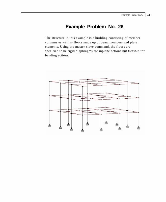
Example Problem 26 243
Example Problem No. 26
The structure in this example is a building consisting of member columns as well as floors made up of beam members and plate elements. Using the master-slave command, the floors are specified to be rigid diaphragms for inplane actions but flexible for bending actions.

Part I - Application Examples
Example Problem 26 244
STAAD SPACE *MODELING RIGID DIAPHRAGMS USING MASTER SLAVE
Every STAAD input file has to begin with the word STAAD. The word SPACE signifies that the structure is a space frame and the geometry is defined through X, Y and Z axes. The second line is an optional title to identify this project.
UNITS KIP FT
Specify units for the following data.
JOINT COORD 1 0 0 0 4 0 48 0 REPEAT 3 24 0 0 REPEAT ALL 3 0 0 24 DELETE JOINT 21 25 37 41
The joint numbers and coordinates are specified above. The unwanted joints, created during the generation process used above, are then deleted.
MEMBER INCI 1 1 2 3 ; 4 5 6 6 ; 7 9 10 9 ; 10 13 14 12 13 17 18 15 ; 22 29 30 24 ; 25 33 34 27 34 45 46 36 ; 37 49 50 39 ; 40 53 54 42 43 57 58 45 ; 46 61 62 48 ; 49 2 6 51 52 6 10 54 ; 55 10 14 57 ; 58 18 22 60 61 22 26 63 ; 64 26 30 66 ; 67 34 38 69 70 38 42 72 ; 73 42 46 75 ; 76 50 54 78 79 54 58 81 ; 82 58 62 84 ; 85 18 2 87 88 22 6 90 ; 91 26 10 93 ; 94 30 14 96 97 34 18 99 ; 100 38 22 102 ; 103 42 26 105 106 46 30 108 ; 109 50 34 111 ; 112 54 38 114 115 58 42 117 ; 118 62 46 120
The MEMBER INCIDENCE specification is used for specifying MEMBER connectivities.

Example Problem 26 245
ELEMENT INCI 152 50 34 38 54 TO 154 155 54 38 42 58 TO 157 158 58 42 46 62 TO 160 161 34 18 22 38 TO 163 164 38 22 26 42 TO 166 167 42 26 30 46 TO 169 170 18 2 6 22 TO 172 173 22 6 10 26 TO 175 176 26 10 14 30 TO 178
The ELEMENT INCIDENCE specification is used for specifying plate element connectivities.
MEMBER PROPERTIES AMERICAN 1 TO 15 22 TO 27 34 TO 48 TA ST W14X90 49 TO 120 TABLE ST W27X84
All members are WIDE FLANGE sections whose properties are obtained from the built in American steel table.
ELEMENT PROP 152 TO 178 THICK 0.75
The thickness of the plate elements is specified above.
CONSTANTS E STEEL MEMB 1 TO 15 22 TO 27 34 TO 120 DENSITY STEEL MEMB 1 TO 15 22 TO 27 34 TO 120 POISSON STEEL MEMB 1 TO 15 22 TO 27 34 TO 120 BETA 90.0 MEMB 13 14 15 22 TO 27 34 TO 39 E CONCRETE MEMB 152 TO 178 DENSITY CONCRETE MEMB 152 TO 178 POISSON CONCRETE MEMB 152 TO 178
Following the command CONSTANTS above, the material constants such as E (Modulus of Elasticity), Poisson's Ratio, and Density are specified. Built-in default values for steel and concrete

Part I - Application Examples
Example Problem 26 246
for these quantities are assigned. The orientation of some of the members is set using the BETA angle command.
SUPPORTS 1 TO 17 BY 4 29 33 45 TO 61 BY 4 FIXED
The supports at the above mentioned joints are declared as fixed.
SLAVE DIA ZX MASTER 22 JOINTS YR 15.0 17.0 SLAVE DIA ZX MASTER 23 JOINTS YR 31.0 33.0 SLAVE DIA ZX MASTER 24 JOINTS YR 47.0 49.0
The 3 floors of the structure are specified to act as rigid diaphragms in the ZX plane with the corresponding master joint specified. The associated slave joints in a floor are specified by the YRANGE parameter. The floors may still resist out-of-plane bending actions flexibly.
LOADING 1 LATERAL LOADS JOINT LOADS 2 3 4 14 15 16 50 51 52 62 63 64 FZ 10.0 6 7 8 10 11 12 18 19 20 30 31 32 FZ 20.0 34 35 36 46 47 48 54 55 56 58 59 60 FZ 20.0 22 23 24 26 27 28 38 39 40 42 43 44 FZ 40.0
The above data describe a static load case. It consists of joint loads in the global Z direction.
LOADING 2 TORSIONAL LOADS JOINT LOADS 2 3 4 50 51 52 FZ 5.0 14 15 16 62 63 64 FZ 15.0 6 7 8 18 19 20 FZ 10.0 10 11 12 30 31 32 FZ 30.0 34 35 36 54 55 56 FZ 10.0 46 47 48 58 59 60 FZ 30.0 22 23 24 38 39 40 FZ 20.0 26 27 28 42 43 44 FZ 60.0
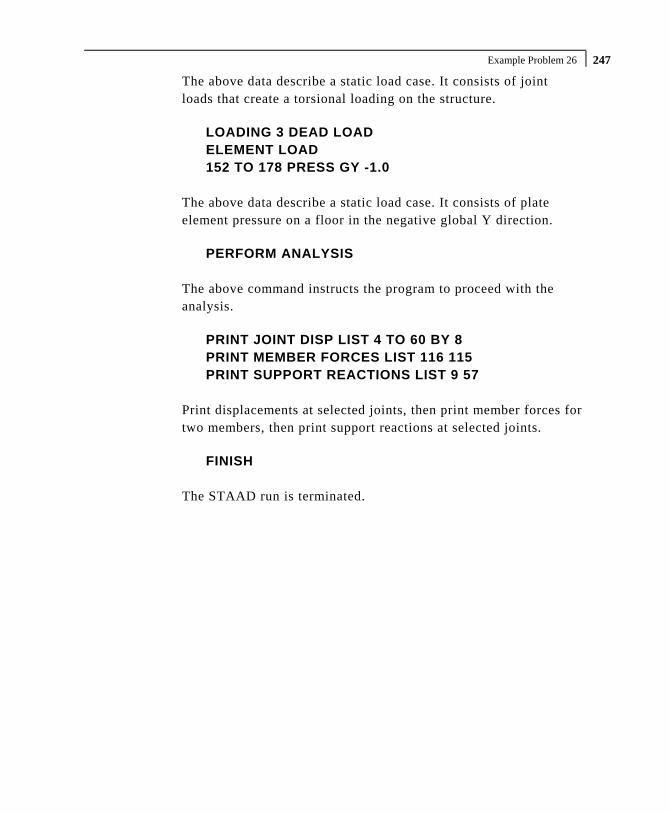
Example Problem 26 247
The above data describe a static load case. It consists of joint loads that create a torsional loading on the structure.
LOADING 3 DEAD LOAD ELEMENT LOAD 152 TO 178 PRESS GY -1.0
The above data describe a static load case. It consists of plate element pressure on a floor in the negative global Y direction.
PERFORM ANALYSIS
The above command instructs the program to proceed with the analysis.
PRINT JOINT DISP LIST 4 TO 60 BY 8 PRINT MEMBER FORCES LIST 116 115 PRINT SUPPORT REACTIONS LIST 9 57
Print displacements at selected joints, then print member forces for two members, then print support reactions at selected joints.
FINISH
The STAAD run is terminated.

Part I - Application Examples
Example Problem 26 248 **************************************************** * * * STAAD.Pro * * Version 2007 Build 02 * * Proprietary Program of * * Research Engineers, Intl. * * Date= * * Time= * * * * USER ID: * **************************************************** 1. STAAD SPACE 2. *MODELING RIGID DIAPHRAGMS USING MASTER SLAVE 3. UNITS KIP FT 4. JOINT COORD 5. 1 0 0 0 4 0 48 0 6. REPEAT 3 24 0 0 7. REPEAT ALL 3 0 0 24 8. DELETE JOINT 21 25 37 41 9. MEMBER INCI 10. 1 1 2 3 ; 4 5 6 6 ; 7 9 10 9 ; 10 13 14 12 11. 13 17 18 15 ; 22 29 30 24 ; 25 33 34 27 12. 34 45 46 36 ; 37 49 50 39 ; 40 53 54 42 13. 43 57 58 45 ; 46 61 62 48 ; 49 2 6 51 14. 52 6 10 54 ; 55 10 14 57 ; 58 18 22 60 15. 61 22 26 63 ; 64 26 30 66 ; 67 34 38 69 16. 70 38 42 72 ; 73 42 46 75 ; 76 50 54 78 17. 79 54 58 81 ; 82 58 62 84 ; 85 18 2 87 18. 88 22 6 90 ; 91 26 10 93 ; 94 30 14 96 19. 97 34 18 99 ; 100 38 22 102 ; 103 42 26 105 20. 106 46 30 108 ; 109 50 34 111 ; 112 54 38 114 21. 115 58 42 117 ; 118 62 46 120 22. ELEMENT INCI 23. 152 50 34 38 54 TO 154 24. 155 54 38 42 58 TO 157 25. 158 58 42 46 62 TO 160 26. 161 34 18 22 38 TO 163 27. 164 38 22 26 42 TO 166 28. 167 42 26 30 46 TO 169 29. 170 18 2 6 22 TO 172 30. 173 22 6 10 26 TO 175 31. 176 26 10 14 30 TO 178 32. MEMBER PROPERTIES AMERICAN 33. 1 TO 15 22 TO 27 34 TO 48 TA ST W14X90 34. 49 TO 120 TABLE ST W27X84 35. ELEMENT PROP 36. 152 TO 178 THICK 0.75 37. CONSTANTS 38. E STEEL MEMB 1 TO 15 22 TO 27 34 TO 120 39. DENSITY STEEL MEMB 1 TO 15 22 TO 27 34 TO 120 40. POISSON STEEL MEMB 1 TO 15 22 TO 27 34 TO 120 41. BETA 90.0 MEMB 13 14 15 22 TO 27 34 TO 39 42. E CONCRETE MEMB 152 TO 178 43. DENSITY CONCRETE MEMB 152 TO 178 44. POISSON CONCRETE MEMB 152 TO 178 45. SUPPORTS 46. 1 TO 17 BY 4 29 33 45 TO 61 BY 4 FIXED 47. SLAVE DIA ZX MASTER 22 JOINTS YR 15.0 17.0 48. SLAVE DIA ZX MASTER 23 JOINTS YR 31.0 33.0 49. SLAVE DIA ZX MASTER 24 JOINTS YR 47.0 49.0 50. LOADING 1 LATERAL LOADS 51. JOINT LOADS 52. 2 3 4 14 15 16 50 51 52 62 63 64 FZ 10.0 53. 6 7 8 10 11 12 18 19 20 30 31 32 FZ 20.0 54. 34 35 36 46 47 48 54 55 56 58 59 60 FZ 20.0 55. 22 23 24 26 27 28 38 39 40 42 43 44 FZ 40.0 56. LOADING 2 TORSIONAL LOADS 57. JOINT LOADS 58. 2 3 4 50 51 52 FZ 5.0 59. 14 15 16 62 63 64 FZ 15.0 60. 6 7 8 18 19 20 FZ 10.0 61. 10 11 12 30 31 32 FZ 30.0

Example Problem 26 249
62. 34 35 36 54 55 56 FZ 10.0 63. 46 47 48 58 59 60 FZ 30.0 64. 22 23 24 38 39 40 FZ 20.0 65. 26 27 28 42 43 44 FZ 60.0 66. LOADING 3 DEAD LOAD 67. ELEMENT LOAD 68. 152 TO 178 PRESS GY -1.0 69. PERFORM ANALYSIS P R O B L E M S T A T I S T I C S ----------------------------------- NUMBER OF JOINTS/MEMBER+ELEMENTS/SUPPORTS = 60/ 135/ 12 SOLVER USED IS THE IN-CORE ADVANCED SOLVER TOTAL PRIMARY LOAD CASES = 3, TOTAL DEGREES OF FREEDOM = 153 70. PRINT JOINT DISP LIST 4 TO 60 BY 8 JOINT DISPLACEMENT (INCH RADIANS) STRUCTURE TYPE = SPACE ------------------ JOINT LOAD X-TRANS Y-TRANS Z-TRANS X-ROTAN Y-ROTAN Z-ROTAN 4 1 0.23216 0.04609 8.13263 0.00108 -0.00056 -0.00008 2 1.49676 0.04919 6.87442 0.00090 -0.00363 -0.00046 3 0.02679 -0.19716 -0.32921 0.00792 -0.00041 -0.00625 12 1 0.23216 0.02166 8.45739 0.00159 -0.00056 0.00014 2 1.49676 0.02716 8.96702 0.00166 -0.00363 0.00000 3 0.02679 -0.86713 -0.09027 0.07454 -0.00041 0.00495 20 1 0.06978 -0.00054 8.13263 0.00120 -0.00056 -0.00025 2 0.45046 0.00140 6.87442 0.00103 -0.00363 -0.00031 3 -0.09268 -0.88242 -0.32921 0.00452 -0.00041 -0.07454 28 1 0.06978 -0.07792 8.45739 -0.00058 -0.00056 0.00024 2 0.45046 -0.07823 8.96702 -0.00059 -0.00363 0.00028 3 -0.09268 -21.50252 -0.09027 0.04716 -0.00041 0.04703 36 1 -0.09261 0.02065 8.13263 0.00102 -0.00056 0.00030 2 -0.59584 0.01536 6.87442 0.00088 -0.00363 0.00036 3 -0.21215 -0.86781 -0.32921 -0.00503 -0.00041 -0.07452 44 1 -0.09261 0.08468 8.45739 -0.00057 -0.00056 -0.00028 2 -0.59584 0.08128 8.96702 -0.00059 -0.00363 -0.00031 3 -0.21215 -21.51350 -0.09027 -0.04712 -0.00041 0.04704 52 1 -0.25499 -0.06556 8.13263 0.00245 -0.00056 -0.00002 2 -1.64214 -0.06312 6.87442 0.00207 -0.00363 0.00017 3 -0.33161 -0.19363 -0.32921 -0.00649 -0.00041 -0.00791 60 1 -0.25499 -0.02115 8.45739 0.00162 -0.00056 -0.00014 2 -1.64214 -0.02678 8.96702 0.00167 -0.00363 0.00001 3 -0.33161 -0.86677 -0.09027 -0.07468 -0.00041 0.00504 ************** END OF LATEST ANALYSIS RESULT ************** 71. PRINT MEMBER FORCES LIST 116 115 MEMBER END FORCES STRUCTURE TYPE = SPACE ----------------- ALL UNITS ARE -- KIP FEET (LOCAL ) MEMBER LOAD JT AXIAL SHEAR-Y SHEAR-Z TORSION MOM-Y MOM-Z 116 1 59 0.00 4.73 0.00 0.00 0.00 198.84 43 0.00 -4.73 0.00 0.00 0.00 -85.38 2 59 0.00 5.10 0.00 -0.01 0.00 208.23 43 0.00 -5.10 0.00 0.01 0.00 -85.83 3 59 0.00 129.34 0.00 0.32 0.00 1407.27 43 0.00 -129.34 0.00 -0.32 0.00 1696.94 115 1 58 0.00 7.70 0.00 -0.01 0.00 322.14 42 0.00 -7.70 0.00 0.01 0.00 -137.41 2 58 0.00 8.32 0.00 -0.01 0.00 336.88 42 0.00 -8.32 0.00 0.01 0.00 -137.13 3 58 0.00 125.39 0.00 0.34 0.00 1173.82 42 0.00 -125.39 0.00 -0.34 0.00 1835.58 ************** END OF LATEST ANALYSIS RESULT **************

Part I - Application Examples
Example Problem 26 250 72. PRINT SUPPORT REACTIONS LIST 9 57 SUPPORT REACTIONS -UNIT KIP FEET STRUCTURE TYPE = SPACE ----------------- JOINT LOAD FORCE-X FORCE-Y FORCE-Z MOM-X MOM-Y MOM Z 9 1 -6.98 -54.60 -54.87 -470.13 0.01 50.69 2 -28.54 -69.17 -58.55 -500.63 0.03 231.31 3 -14.10 1732.37 92.25 487.26 0.00 70.68 57 1 7.65 53.36 -54.76 -469.56 0.01 -55.90 2 31.74 68.14 -58.52 -500.47 0.03 -257.51 3 -11.82 1731.53 -91.91 -483.96 0.00 51.09 ************** END OF LATEST ANALYSIS RESULT ************** 73. FINISH *********** END OF THE STAAD.Pro RUN *********** **** DATE= TIME= **** ************************************************************ * For questions on STAAD.Pro, please contact * * Research Engineers Offices at the following locations * * * * Telephone Email * * USA: +1 (714)974-2500 [email protected] * * CANADA +1 (905)632-4771 [email protected] * * UK +44(1454)207-000 [email protected] * * FRANCE +33(0)1 64551084 [email protected] * * GERMANY +49/931/40468-71 [email protected] * * NORWAY +47 67 57 21 30 [email protected] * * SINGAPORE +65 6225-6158 [email protected] * * INDIA +91(033)4006-2021 [email protected] * * JAPAN +81(03)5952-6500 [email protected] * * CHINA +86(411)363-1983 [email protected] * * THAILAND +66(0)2645-1018/19 [email protected] * * * * North America [email protected] * * Europe [email protected] * * Asia [email protected] * ************************************************************

Example Problem 27 251
Example Problem No. 27
This example illustrates the usage of commands necessary to apply the compression only attribute to spring supports for a slab on grade. The spring supports themselves are generated utilizing the built-in support generation facility. The slab is subjected to pressure and overturning loading. A tension/compression only analysis of the structure is performed. The numbers shown in the diagram below are the element numbers.

Part I - Application Examples
Example Problem 27 252
STAAD SPACE SLAB ON GRADE * SPRING COMPRESSION EXAMPLE
Every STAAD input file has to begin with the word STAAD. The word SPACE signifies that the structure is a space frame and the geometry is defined through X, Y and Z axes. An optional title to identify this project is provided in the second line.
SET NL 3
This structure has to be analysed for 3 primary load cases. Consequently, the modeling of our problem requires us to define 3 sets of data, with each set containing a load case and an associated analysis command. Also, the supports which get switched off in the analysis for any load case have to be restored for the analysis for the subsequent load case. To accommodate these requirements, it is necessary to have 2 commands, one called “SET NL” and the other called “CHANGE”. The SET NL command is used above to indicate the total number of primary load cases that the file contains. The CHANGE command will come in later (after the PERFORM ANALYSIS command).
UNIT FEET KIP JOINT COORDINATES 1 0.0 0.0 40.0 2 0.0 0.0 36.0 3 0.0 0.0 28.167 4 0.0 0.0 20.333 5 0.0 0.0 12.5 6 0.0 0.0 6.5 7 0.0 0.0 0.0 REPEAT ALL 3 8.5 0.0 0.0 REPEAT 3 8.0 0.0 0.0 REPEAT 5 6.0 0.0 0.0 REPEAT 3 8.0 0.0 0.0 REPEAT 3 8.5 0.0 0.0
For joints 1 through 7, the joint number followed by the X, Y and Z coordinates are specified above. The coordinates of these joints is used as a basis for generating 21 more joints by incrementing the X coordinate of each of these 7 joints by 8.5 feet, 3 times.

Example Problem 27 253
REPEAT commands are used to generate the remaining joints of the structure. The results of the generation may be visually verified using the STAAD graphical viewing facilities.
ELEMENT INCIDENCES 1 1 8 9 2 TO 6 REPEAT 16 6 7
The incidences of element number 1 is defined and that data is used as a basis for generating the 2nd through the 6th element. The incidence pattern of the first 6 elements is then used to generate the incidences of 96 more elements using the REPEAT command.
UNIT INCH ELEMENT PROPERTIES 1 TO 102 TH 8.0
The thickness of elements 1 to 102 is specified as 8.0 inches following the command ELEMENT PROPERTIES.
CONSTANTS E 4000.0 ALL POISSON 0.12 ALL
The modulus of elasticity (E) and density are specified following the command CONSTANTS.
SPRING COMPRESSION 1 TO 126 KFY
The above two lines declare the spring supports at nodes 1 to 126 as having the compression-only attribute. The supports themselves are being generated later (see the ELASTIC MAT command which appears later).
UNIT FEET SUPPORTS 1 TO 126 ELASTIC MAT DIRECTION Y SUBGRADE 12.0

Part I - Application Examples
Example Problem 27 254
The above command is used to instruct STAAD to generate supports with compression-only springs which are effective in the global Y direction. These springs are located at nodes 1 to 126. The subgrade reaction of the soil is specified as 12 kip/cu.ft. The program will determine the area under the influence of each joint and multiply the influence area by the subgrade reaction to arrive at the spring stiffness for the "FY" degree of freedom at the joint. Units for length are changed to FEET to facilitate the input of subgrade reaction of soil. Additional information on this feature may be found in the STAAD Technical Reference Manual.
LOAD 1 'WEIGHT OF MAT & EARTH' ELEMENT LOAD 1 TO 102 PR GY -1.50
The above data describe a static load case. A pressure load of 1.50 kip/ft acting in the negative global Y direction is applied on all the elements.
PERFORM ANALYSIS PRINT STATICS CHECK CHANGE
Tension/compression cases must each be followed by PERFORM ANALYSIS and CHANGE commands. The CHANGE command restores the original structure to prepare it for the analysis for the next primary load case.
LOAD 2 'COLUMN LOAD-DL+LL' JOINT LOADS 1 2 FY -217. 8 9 FY -109. 5 FY -308.7 6 FY -617.4 22 23 FY -410. 29 30 FY -205. 26 FY -542.7 27 FY -1085.4 43 44 50 51 71 72 78 79 FY -307.5 47 54 82 FY -264.2

Example Problem 27 255
48 55 76 83 FY -528.3 92 93 FY -205.0 99 100 FY -410.0 103 FY -487.0 104 FY -974.0 113 114 FY -109.0 120 121 FY -217.0 124 FY -273.3 125 FY -546.6 PERFORM ANALYSIS PRINT STATICS CHECK CHANGE
Load case 2 consists of several joint loads acting in the negative global Y direction. This is followed by another ANALYSIS command. The CHANGE command restores the original structure once again for the forthcoming load case.
LOAD 3 'COLUMN OVERTURNING LOAD' ELEMENT LOAD 1 TO 102 PR GY -1.50 JOINT LOADS 1 2 FY -100. 8 9 FY -50. 5 FY -150.7 6 FY -310.4 22 23 FY -205. 29 30 FY -102. 26 FY -271.7 27 FY -542.4 43 44 50 51 71 72 78 79 FY -153.5 47 54 82 FY -132.2 48 55 76 83 FY -264.3 92 93 FY 102.0 99 100 FY 205.0 103 FY 243.0 104 FY 487.0 113 114 FY 54.0 120 121 FY 108.0

Part I - Application Examples
Example Problem 27 256
124 FY 136.3 125 FY 273.6 PERFORM ANALYSIS PRINT STATICS CHECK
Load case 3 consists of several joint loads acting in the upward direction at one end and downward on the other end to apply an overturning moment that will lift off one end. The CHANGE command is not needed after the last analysis.
LOAD LIST 3 PRINT JOINT DISPLACEMENTS LIST 113 114 120 121 PRINT ELEMENT STRESSES LIST 34 67 PRINT SUPPORT REACTIONS LIST 5 6 12 13
A list of joint displacements, element stresses for elements 34 and 67, and support reactions at a list of joints for load case 3, are obtained with the help of the above commands.
FINISH
The STAAD run is terminated.
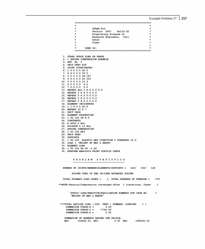
Example Problem 27 257
**************************************************** * * * STAAD.Pro * * Version 2007 Build 02 * * Proprietary Program of * * Research Engineers, Intl. * * Date= * * Time= * * * * USER ID: * **************************************************** 1. STAAD SPACE SLAB ON GRADE 2. * SPRING COMPRESSION EXAMPLE 3. SET NL 3 4. UNIT FEET KIP 5. JOINT COORDINATES 6. 1 0.0 0.0 40.0 7. 2 0.0 0.0 36.0 8. 3 0.0 0.0 28.167 9. 4 0.0 0.0 20.333 10. 5 0.0 0.0 12.5 11. 6 0.0 0.0 6.5 12. 7 0.0 0.0 0.0 13. REPEAT ALL 3 8.5 0.0 0.0 14. REPEAT 3 8.0 0.0 0.0 15. REPEAT 5 6.0 0.0 0.0 16. REPEAT 3 8.0 0.0 0.0 17. REPEAT 3 8.5 0.0 0.0 18. ELEMENT INCIDENCES 19. 1 1 8 9 2 TO 6 20. REPEAT 16 6 7 21. UNIT INCH 22. ELEMENT PROPERTIES 23. 1 TO 102 TH 8.0 24. CONSTANTS 25. E 4000.0 ALL 26. POISSON 0.12 ALL 27. SPRING COMPRESSION 28. 1 TO 126 KFY 29. UNIT FEET 30. SUPPORTS 31. 1 TO 126 ELASTIC MAT DIRECTION Y SUBGRADE 12.0 32. LOAD 1 'WEIGHT OF MAT & EARTH' 33. ELEMENT LOAD 34. 1 TO 102 PR GY -1.50 35. PERFORM ANALYSIS PRINT STATICS CHECK P R O B L E M S T A T I S T I C S ----------------------------------- NUMBER OF JOINTS/MEMBER+ELEMENTS/SUPPORTS = 126/ 102/ 126 SOLVER USED IS THE IN-CORE ADVANCED SOLVER TOTAL PRIMARY LOAD CASES = 1, TOTAL DEGREES OF FREEDOM = 378 **NOTE-Tension/Compression converged after 1 iterations, Case= 1 STATIC LOAD/REACTION/EQUILIBRIUM SUMMARY FOR CASE NO. 1 'WEIGHT OF MAT & EARTH' ***TOTAL APPLIED LOAD ( KIP FEET ) SUMMARY (LOADING 1 ) SUMMATION FORCE-X = 0.00 SUMMATION FORCE-Y = -7740.00 SUMMATION FORCE-Z = 0.00 SUMMATION OF MOMENTS AROUND THE ORIGIN- MX= 154800.01 MY= 0.00 MZ= -499230.03

Part I - Application Examples
Example Problem 27 258 ***TOTAL REACTION LOAD( KIP FEET ) SUMMARY (LOADING 1 ) SUMMATION FORCE-X = 0.00 SUMMATION FORCE-Y = 7740.00 SUMMATION FORCE-Z = 0.00 SUMMATION OF MOMENTS AROUND THE ORIGIN- MX= -154800.01 MY= 0.00 MZ= 499230.03 MAXIMUM DISPLACEMENTS ( INCH /RADIANS) (LOADING 1) MAXIMUMS AT NODE X = 0.00000E+00 0 Y = -1.50000E+00 1 Z = 0.00000E+00 0 RX= 9.51342E-10 2 RY= 0.00000E+00 0 RZ= 4.19726E-10 45 ************ END OF DATA FROM INTERNAL STORAGE ************ 36. CHANGE 37. LOAD 2 'COLUMN LOAD-DL+LL' 38. JOINT LOADS 39. 1 2 FY -217. 40. 8 9 FY -109. 41. 5 FY -308.7 42. 6 FY -617.4 43. 22 23 FY -410. 44. 29 30 FY -205. 45. 26 FY -542.7 46. 27 FY -1085.4 47. 43 44 50 51 71 72 78 79 FY -307.5 48. 47 54 82 FY -264.2 49. 48 55 76 83 FY -528.3 50. 92 93 FY -205.0 51. 99 100 FY -410.0 52. 103 FY -487.0 53. 104 FY -974.0 54. 113 114 FY -109.0 55. 120 121 FY -217.0 56. 124 FY -273.3 57. 125 FY -546.6 58. PERFORM ANALYSIS PRINT STATICS CHECK **NOTE-Tension/Compression converged after 1 iterations, Case= 2 STATIC LOAD/REACTION/EQUILIBRIUM SUMMARY FOR CASE NO. 2 'COLUMN LOAD-DL+LL' ***TOTAL APPLIED LOAD ( KIP FEET ) SUMMARY (LOADING 2 ) SUMMATION FORCE-X = 0.00 SUMMATION FORCE-Y = -13964.90 SUMMATION FORCE-Z = 0.00 SUMMATION OF MOMENTS AROUND THE ORIGIN- MX= 301253.66 MY= 0.00 MZ= -884991.47 ***TOTAL REACTION LOAD( KIP FEET ) SUMMARY (LOADING 2 ) SUMMATION FORCE-X = 0.00 SUMMATION FORCE-Y = 13964.90 SUMMATION FORCE-Z = 0.00 SUMMATION OF MOMENTS AROUND THE ORIGIN- MX= -301253.66 MY= 0.00 MZ= 884991.47

Example Problem 27 259
MAXIMUM DISPLACEMENTS ( INCH /RADIANS) (LOADING 2) MAXIMUMS AT NODE X = 0.00000E+00 0 Y = -1.09725E+01 120 Z = 0.00000E+00 0 RX= 7.89606E-02 99 RY= 0.00000E+00 0 RZ= 9.69957E-02 6 ************ END OF DATA FROM INTERNAL STORAGE ************ 59. CHANGE 60. LOAD 3 'COLUMN OVERTURNING LOAD' 61. ELEMENT LOAD 62. 1 TO 102 PR GY -1.50 63. JOINT LOADS 64. 1 2 FY -100. 65. 8 9 FY -50. 66. 5 FY -150.7 67. 6 FY -310.4 68. 22 23 FY -205. 69. 29 30 FY -102. 70. 26 FY -271.7 71. 27 FY -542.4 72. 43 44 50 51 71 72 78 79 FY -153.5 73. 47 54 82 FY -132.2 74. 48 55 76 83 FY -264.3 75. 92 93 FY 102.0 76. 99 100 FY 205.0 77. 103 FY 243.0 78. 104 FY 487.0 79. 113 114 FY 54.0 80. 120 121 FY 108.0 81. 124 FY 136.3 82. 125 FY 273.6 83. PERFORM ANALYSIS PRINT STATICS CHECK **START ITERATION NO. 2 **START ITERATION NO. 3 **START ITERATION NO. 4 **START ITERATION NO. 5 **NOTE-Tension/Compression converged after 5 iterations, Case= 3 STATIC LOAD/REACTION/EQUILIBRIUM SUMMARY FOR CASE NO. 3 'COLUMN OVERTURNING LOAD' ***TOTAL APPLIED LOAD ( KIP FEET ) SUMMARY (LOADING 3 ) SUMMATION FORCE-X = 0.00 SUMMATION FORCE-Y = -10533.10 SUMMATION FORCE-Z = 0.00 SUMMATION OF MOMENTS AROUND THE ORIGIN- MX= 213519.36 MY= 0.00 MZ= -478687.78 ***TOTAL REACTION LOAD( KIP FEET ) SUMMARY (LOADING 3 ) SUMMATION FORCE-X = 0.00 SUMMATION FORCE-Y = 10533.10 SUMMATION FORCE-Z = 0.00 SUMMATION OF MOMENTS AROUND THE ORIGIN- MX= -213519.36 MY= 0.00 MZ= 478687.78

Part I - Application Examples
Example Problem 27 260 MAXIMUM DISPLACEMENTS ( INCH /RADIANS) (LOADING 3) MAXIMUMS AT NODE X = 0.00000E+00 0 Y = 2.83669E+01 120 Z = 0.00000E+00 0 RX= -1.22268E-01 120 RY= 0.00000E+00 0 RZ= 1.09786E-01 125 ************ END OF DATA FROM INTERNAL STORAGE ************ 84. LOAD LIST 3 85. PRINT JOINT DISPLACEMENTS LIST 113 114 120 121 JOINT DISPLACEMENT (INCH RADIANS) STRUCTURE TYPE = SPACE ------------------ JOINT LOAD X-TRANS Y-TRANS Z-TRANS X-ROTAN Y-ROTAN Z-ROTAN 113 3 0.00000 19.17264 0.00000 -0.09579 0.00000 0.06945 114 3 0.00000 14.53915 0.00000 -0.09437 0.00000 0.06506 120 3 0.00000 28.36691 0.00000 -0.12227 0.00000 0.10056 121 3 0.00000 22.49737 0.00000 -0.11615 0.00000 0.08912 ************** END OF LATEST ANALYSIS RESULT ************** 86. PRINT ELEMENT STRESSES LIST 34 67 ELEMENT STRESSES FORCE,LENGTH UNITS= KIP FEET ---------------- STRESS = FORCE/UNIT WIDTH/THICK, MOMENT = FORCE-LENGTH/UNIT WIDTH ELEMENT LOAD SQX SQY MX MY MXY VONT VONB SX SY SXY TRESCAT TRESCAB 34 3 -4.50 -6.74 2.45 7.99 6.96 188.81 188.81 0.00 0.00 0.00 202.25 202.25 TOP : SMAX= 171.62 SMIN= -30.64 TMAX= 101.13 ANGLE= -34.2 BOTT: SMAX= 30.64 SMIN= -171.62 TMAX= 101.13 ANGLE= -34.2 67 3 37.83 6.21 -57.38 5.58 43.51 1303.44 1303.44 0.00 0.00 0.00 1449.91 1449.91 TOP : SMAX= 375.29 SMIN= -1074.62 TMAX= 724.96 ANGLE= -27.1 BOTT: SMAX= 1074.62 SMIN= -375.29 TMAX= 724.96 ANGLE= -27.1 **** MAXIMUM STRESSES AMONG SELECTED PLATES AND CASES **** MAXIMUM MINIMUM MAXIMUM MAXIMUM MAXIMUM PRINCIPAL PRINCIPAL SHEAR VONMISES TRESCA STRESS STRESS STRESS STRESS STRESS 1.074621E+03 -1.074621E+03 7.249564E+02 1.303438E+03 1.449913E+03 PLATE NO. 67 67 67 67 67 CASE NO. 3 3 3 3 3 ********************END OF ELEMENT FORCES******************** 87. PRINT SUPPORT REACTIONS LIST 5 6 12 13

Example Problem 27 261
SUPPORT REACTIONS -UNIT KIP FEET STRUCTURE TYPE = SPACE ----------------- JOINT LOAD FORCE-X FORCE-Y FORCE-Z MOM-X MOM-Y MOM Z 5 3 0.00 148.06 0.00 0.00 0.00 0.00 6 3 0.00 168.10 0.00 0.00 0.00 0.00 12 3 0.00 149.08 0.00 0.00 0.00 0.00 13 3 0.00 153.60 0.00 0.00 0.00 0.00 ************** END OF LATEST ANALYSIS RESULT ************** 88. FINISH *********** END OF THE STAAD.Pro RUN *********** **** DATE= TIME= **** ************************************************************ * For questions on STAAD.Pro, please contact * * Research Engineers Offices at the following locations * * * * Telephone Email * * USA: +1 (714)974-2500 [email protected] * * CANADA +1 (905)632-4771 [email protected] * * UK +44(1454)207-000 [email protected] * * FRANCE +33(0)1 64551084 [email protected] * * GERMANY +49/931/40468-71 [email protected] * * NORWAY +47 67 57 21 30 [email protected] * * SINGAPORE +65 6225-6158 [email protected] * * INDIA +91(033)4006-2021 [email protected] * * JAPAN +81(03)5952-6500 [email protected] * * CHINA +86(411)363-1983 [email protected] * * THAILAND +66(0)2645-1018/19 [email protected] * * * * North America [email protected] * * Europe [email protected] * * Asia [email protected] * ************************************************************

Part I - Application Examples
Example Problem 27 262
NOTES

Example Problem 28 263
Example Problem No. 28
This example demonstrates the input required for obtaining the modes and frequencies of the skewed bridge shown in the figure below. The structure consists of piers, pier-cap girders and a deck slab.
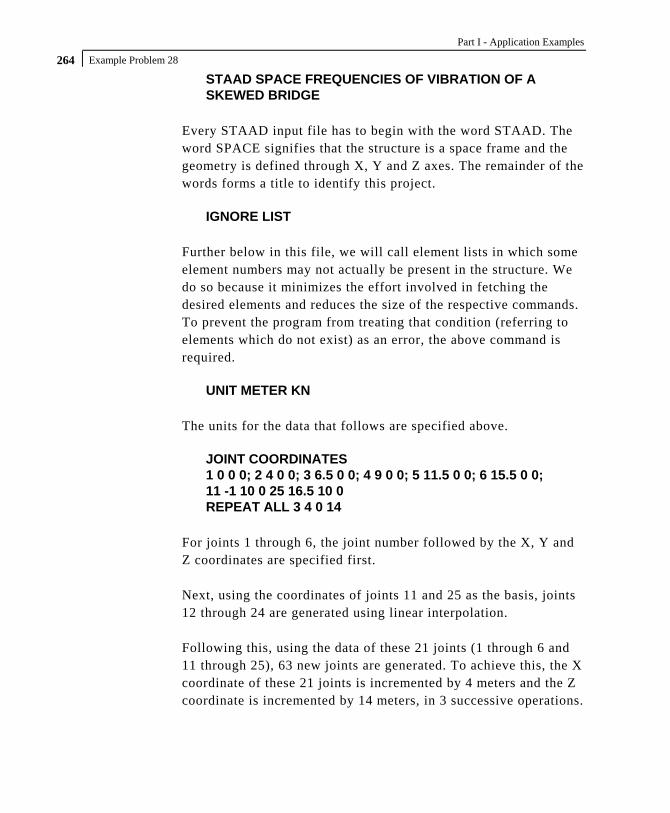
Part I - Application Examples
Example Problem 28 264
STAAD SPACE FREQUENCIES OF VIBRATION OF A SKEWED BRIDGE
Every STAAD input file has to begin with the word STAAD. The word SPACE signifies that the structure is a space frame and the geometry is defined through X, Y and Z axes. The remainder of the words forms a title to identify this project.
IGNORE LIST Further below in this file, we will call element lists in which some element numbers may not actually be present in the structure. We do so because it minimizes the effort involved in fetching the desired elements and reduces the size of the respective commands. To prevent the program from treating that condition (referring to elements which do not exist) as an error, the above command is required.
UNIT METER KN The units for the data that follows are specified above.
JOINT COORDINATES 1 0 0 0; 2 4 0 0; 3 6.5 0 0; 4 9 0 0; 5 11.5 0 0; 6 15.5 0 0; 11 -1 10 0 25 16.5 10 0 REPEAT ALL 3 4 0 14
For joints 1 through 6, the joint number followed by the X, Y and Z coordinates are specified first. Next, using the coordinates of joints 11 and 25 as the basis, joints 12 through 24 are generated using linear interpolation. Following this, using the data of these 21 joints (1 through 6 and 11 through 25), 63 new joints are generated. To achieve this, the X coordinate of these 21 joints is incremented by 4 meters and the Z coordinate is incremented by 14 meters, in 3 successive operations.

Example Problem 28 265
The REPEAT ALL command is used for the generation. Details of this command is available in Section 5.11 of the Technical Reference manual. The results of the generation may be visually verified using STAAD.Pro's graphical viewing facilities.
MEMBER INCI 1 1 13 ; 2 2 15 ; 3 3 17 ; 4 4 19 ; 5 5 21 ; 6 6 23 26 26 34 ; 27 27 36 ; 28 28 38 ; 29 29 40 ; 30 30 42 ; 31 31 44 47 47 55 ; 48 48 57 ; 49 49 59 ; 50 50 61 ; 51 51 63 ; 52 52 65 68 68 76 ; 69 69 78 ; 70 70 80 ; 71 71 82 ; 72 72 84 ; 73 73 86
The member connectivity data (joint numbers between which members are connected) is specified for the 24 columns for the structure. The above method, where the member number is followed by the 2 node numbers, is the explicit definition method. No generation is involved here.
101 11 12 114 202 32 33 215 303 53 54 316 404 74 75 417
The member connectivity data is specified for the pier cap beams for the structure. The above method is a combination of explicit definition and generation. For example, member 101 is defined as connected between 11 & 12. Then, by incrementing those nodes by 1 unit at a time (which is the default increment), the incidences of members 102 to 114 are generated. Similarly, we create members 202 to 215, 303 to 316, and, 404 to 417.
DEFINE MESH A JOINT 11 B JOINT 25 C JOINT 46 D JOINT 32 E JOINT 67 F JOINT 53 G JOINT 88 H JOINT 74
Part I - Application Examples
Example Problem 28 266
The next step is to generate the deck slab which will be modeled using plate elements. For this, we use a technique called mesh generation. Mesh generation is a process of generating several "child" elements from a "parent" or "super" element. The above set of commands defines the corner nodes of the super-element. Details of the above can be found in Section 5.14 of the Technical Reference manual. Note that instead of elaborately defining the coordinates of the corner nodes of the super-elements, we have taken advantage of the fact that the coordinates of these joints (A through H) have already been defined or generated earlier. Thus, A is the same as joint 11 while D is the same as joint 32. Alternatively, we could have defined the super-element nodes as A -1 10 0 ; B 16.5 10 0 ; C 20.5 10 14 ; D 3 10 14 ; etc.
GENERATE ELEMENT MESH ABCD 14 12 MESH DCEF 14 12 MESH FEGH 14 12
The above lines are the instructions for generating the “child” elements from the super-elements. For example, from the super-element bound by the corners A, B, C and D (which in turn are nodes 11, 25, 46 and 32), we generate a total of 14X12=168 elements, with 14 divisions along the edges AB and CD, and 12 along the edges BC and DA. These are the elements which make up the first span. Similarly, 168 elements are created for the 2nd span, and another 168 for the 3rd span. It may be noted here that we have taken great care to ensure that the resulting elements and the piercap beams form a perfect fit. In other words, there is no overlap between the two in a manner that nodes of the beams are at a different point in space than nodes of elements. At every node along their common boundary, plates and beams are properly connected. This is absolutely essential to ensure proper transfer of load and stiffness from beams to plates

Example Problem 28 267
and vice versa. The tools of the graphical user interface may be used to confirm that beam-plate connectivity is proper for this model.
START GROUP DEFINITION MEMBER _GIRDERS 101 TO 114 202 TO 215 303 TO 316 404 TO 417 _PIERS 1 TO 6 26 TO 31 47 TO 52 68 TO 73 ELEMENT _P1 447 TO 450 454 TO 457 461 TO 464 468 TO 471 _P2 531 TO 534 538 TO 541 545 TO 548 552 TO 555 _P3 615 TO 618 622 TO 625 629 TO 632 636 TO 639 _P4 713 TO 716 720 TO 723 727 TO 730 734 TO 737 _P5 783 TO 786 790 TO 793 797 TO 800 804 TO 807 _P6 881 TO 884 888 TO 891 895 TO 898 902 TO 905
END GROUP DEFINITION
The above block of data is referred to as formation of groups. Group names are a mechanism by which a single moniker can be used to refer to a cluster of entities, such as members. For our structure, the piercap beams are being grouped to a name called GIRDERS, the pier columns are assigned the name PIERS, and so on. For the deck, a few selected elements are chosen into a few selective groups. The reason is that these elements happen to be right beneath wheels of vehicles whose weight will be used in the frequency calculation.
MEMBER PROPERTY _GIRDERS PRIS YD 0.6 ZD 0.6 _PIERS PRIS YD 1.0
Member properties are assigned as prismatic rectangular sections for the girders, and prismatic circular sections for the columns.
ELEMENT PROPERTY YRA 9 11 TH 0.375

Part I - Application Examples
Example Problem 28 268
The plate elements of the deck slab, which happen to be at a Y elevation of 10 metres (between a YRANGE of 9 metres and 11 metres) are assigned a thickness of 375 mms.
UNIT NEWTON MMS CONSTANTS E 21000 ALL POISSON CONCRETE ALL
The Modulus of elasticity (E) is set to 21000 N/sq.mm for all members. The keyword CONSTANTS has to precede this data. Built-in default value for Poisson's ratio for concrete is also assigned to ALL members and elements.
UNIT KNS METER CONSTANTS DENSITY 24 ALL
Following a change of units, density of concrete is specified.
SUPPORTS 1 TO 6 26 TO 31 47 TO 52 68 TO 73 FIXED
The base nodes of the piers are fully restrained (FIXED supports).
CUT OFF MODE SHAPE 65 Theoretically, a structure has as many modes of vibration as the number of degrees of freedom in the model. However, the limitations of the mathematical process used in extracting modes may limit the number of modes that can actually be extracted. In a large structure, the extraction process can also be very time consuming. Further, not all modes are of equal importance. (One measure of the importance of modes is the participation factor of that mode.) In many cases, the first few modes may be sufficient to obtain a significant portion of the total dynamic response. Due to these reasons, in the absence of any explicit instruction, STAAD calculates only the first 6 modes. This is like saying that the command CUT OFF MODE SHAPE 6 has been specified.

Example Problem 28 269
(Versions of STAAD prior to STAAD.Pro 2000 calculated only 3 modes by default). If the inspection of the first 6 modes reveals that the overall vibration pattern of the structure has not been obtained, one may ask STAAD to compute a larger (or smaller) number of modes with the help of this command. The number that follows this command is the number of modes being requested. In our example, we are asking for 65 modes by specifying CUT OFF MODE SHAPE 65.
UNIT KGS METER LOAD 1 FREQUENCY CALCULATION SELFWEIGHT X 1.0 SELFWEIGHT Y 1.0 SELFWEIGHT Z 1.0 * PERMANENT WEIGHTS ON DECK ELEMENT LOAD YRA 9 11 PR GX 200 YRA 9 11 PR GY 200 YRA 9 11 PR GZ 200 * VEHICLES ON SPANS - ONLY Y & Z EFFECT CONSIDERED ELEMENT LOAD _P1 PR GY 700 _P2 PR GY 700 _P3 PR GY 700 _P4 PR GY 700 _P5 PR GY 700 _P6 PR GY 700
_P1 PR GZ 700 _P2 PR GZ 700 _P3 PR GZ 700 _P4 PR GZ 700 _P5 PR GZ 700 _P6 PR GZ 700
The mathematical method that STAAD uses is called the eigen extraction method. Some information on this is available in Section 1.18.3 of the STAAD.Pro Technical Reference Manual.

Part I - Application Examples
Example Problem 28 270
The method involves 2 matrices - the stiffness matrix, and the mass matrix. The stiffness matrix, usually called the [K] matrix, is assembled using data such as member and element lengths, member and element properties, modulus of elasticty, Poisson's ratio, member and element releases, member offsets, support information, etc. For assembling the mass matrix, called the [M] matrix, STAAD uses the load data specified in the load case in which the MODAL CAL REQ command is specified. So, some of the important aspects to bear in mind are :
1. The input you specify is weights, not masses. Internally, STAAD will convert weights to masses by dividing the input by "g", the acceleration due to gravity.
2. If the structure is declared as a PLANE frame, there are 2 possible directions of vibration - global X, and global Y. If the structure is declared as a SPACE frame, there are 3 possible directions - global X, global Y and global Z. However, this does not guarantee that STAAD will automatically consider the masses for vibration in all the available directions. You have control over and are responsible for specifying the directions in which the masses ought to vibrate. In other words, if a weight is not specified along a certain direction, the corresponding degrees of freedom (such as for example, global X at node 34 hypothetically) will not receive a contribution in the mass matrix. The mass matrix is assembled using only the masses from the weights and directions specified by the user.
In our example, notice that we are specifying the selfweight along global X, Y and Z directions. Similarly, a 200 kg/sq.m pressure load is also specified along all 3 directions on the deck.
But for the truck loads, we choose to apply it on just a few elements in the global Y and Z directions only. The reasoning is something like - for the X direction, the mass is not capable of

Example Problem 28 271
vibrating because the tires allow the truck to roll along X. Remember, this is just a demonstration example, not necessarily what you may wish to do.
The point we wish to illustrate is that if a user wishes to restrict a certain weight to certain directions only, all he/she has to do is not provide the directions in which those weights cannot vibrate in.
3. As much as possible, provide absolute values for the weights. STAAD is programmed to algebraically add the weights at nodes. So, if some weights are specified as positive numbers and others as negative, the total weight at a given node is the algebraic summation of all the weights in the global directions at that node and the mass is then derived from this algebraic resultant.
MODAL CALCULATION REQUESTED This is the command which tells the program that frequencies and modes should be calculated. It is specified inside a load case. In other words, this command accompanies the loads that are to be used in generating the mass matrix. Frequencies and modes have to be calculated also when dynamic analysis such as response spectrum or time history analysis is carried out. But in such analyses, the MODAL CALCULATION REQUESTED command is not explicitly required. When STAAD encounters the commands for response spectrum (see example 11) and time history (see examples 16 and 22), it automatically will carry out a frequency extraction without the help of the MODAL .. command.

Part I - Application Examples
Example Problem 28 272
PERFORM ANALYSIS This initiates the processes which are required to obtain the frequencies. Frequencies, periods and participation factors are automatically reported in the output file when the operation is completed.
FINISH This terminates the STAAD run.

Example Problem 28 273
**************************************************** * * * STAAD.Pro * * Version 2007 Build 02 * * Proprietary Program of * * Research Engineers, Intl. * * Date= * * Time= * * * * USER ID: * **************************************************** 1. STAAD SPACE FREQUENCIES OF VIBRATION OF A SKEWED BRIDGE 2. IGNORE LIST 3. UNIT METER KN 4. JOINT COORDINATES 5. 1 0 0 0; 2 4 0 0; 3 6.5 0 0; 4 9 0 0; 5 11.5 0 0; 6 15.5 0 0 6. 11 -1 10 0 25 16.5 10 0 7. REPEAT ALL 3 4 0 14 8. MEMBER INCI 9. 1 1 13 ; 2 2 15 ; 3 3 17 ; 4 4 19 ; 5 5 21 ; 6 6 23 10. 26 26 34 ; 27 27 36 ; 28 28 38 ; 29 29 40 ; 30 30 42 ; 31 31 44 11. 47 47 55 ; 48 48 57 ; 49 49 59 ; 50 50 61 ; 51 51 63 ; 52 52 65 12. 68 68 76 ; 69 69 78 ; 70 70 80 ; 71 71 82 ; 72 72 84 ; 73 73 86 13. 101 11 12 114 14. 202 32 33 215 15. 303 53 54 316 16. 404 74 75 417 17. DEFINE MESH 18. A JOINT 11 19. B JOINT 25 20. C JOINT 46 21. D JOINT 32 22. E JOINT 67 23. F JOINT 53 24. G JOINT 88 25. H JOINT 74 26. GENERATE ELEMENT 27. MESH ABCD 14 12 28. MESH DCEF 14 12 29. MESH FEGH 14 12 30. START GROUP DEFINITION 31. MEMBER 32. _GIRDERS 101 TO 114 202 TO 215 303 TO 316 404 TO 417 33. _PIERS 1 TO 6 26 TO 31 47 TO 52 68 TO 73 34. ELEMENT 35. _P1 447 TO 450 454 TO 457 461 TO 464 468 TO 471 36. _P2 531 TO 534 538 TO 541 545 TO 548 552 TO 555 37. _P3 615 TO 618 622 TO 625 629 TO 632 636 TO 639 38. _P4 713 TO 716 720 TO 723 727 TO 730 734 TO 737 39. _P5 783 TO 786 790 TO 793 797 TO 800 804 TO 807 40. _P6 881 TO 884 888 TO 891 895 TO 898 902 TO 905 41. END GROUP DEFINITION 42. MEMBER PROPERTY 43. _GIRDERS PRIS YD 0.6 ZD 0.6 44. _PIERS PRIS YD 1.0 45. ELEMENT PROPERTY 46. YRA 9 11 TH 0.375 47. UNIT NEWTON MMS 48. CONSTANTS 49. E 21000 ALL 50. POISSON CONCRETE ALL 51. UNIT KNS METER 52. CONSTANTS 53. DENSITY 24 ALL 54. SUPPORTS 55. 1 TO 6 26 TO 31 47 TO 52 68 TO 73 FIXED 56. CUT OFF MODE SHAPE 65 57. UNIT KGS METER 58. LOAD 1 FREQUENCY CALCULATION 59. SELFWEIGHT X 1.0 60. SELFWEIGHT Y 1.0
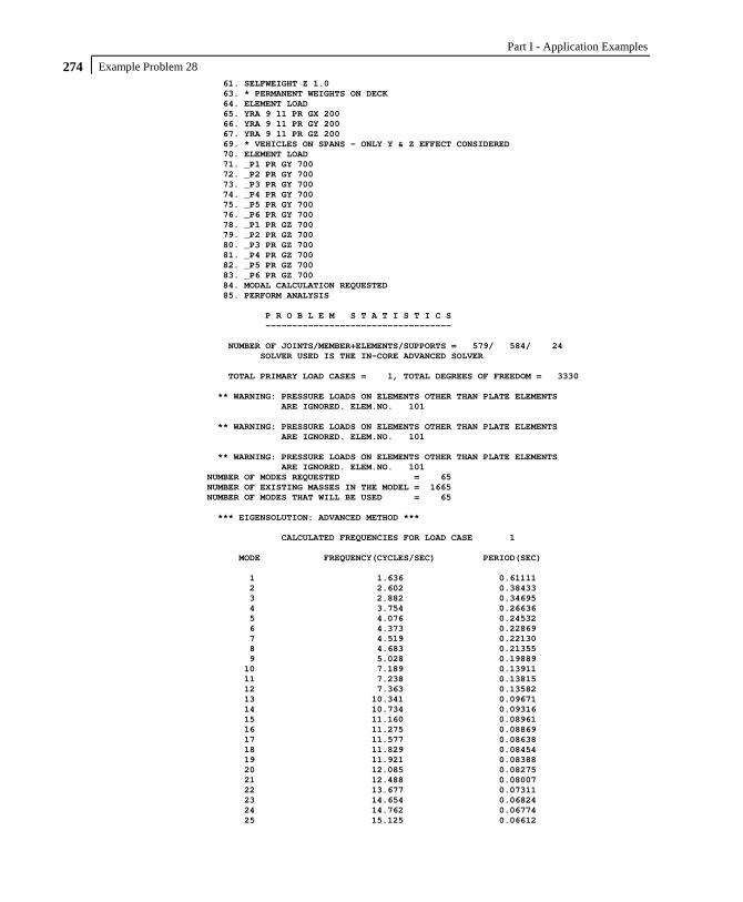
Part I - Application Examples
Example Problem 28 274
61. SELFWEIGHT Z 1.0 63. * PERMANENT WEIGHTS ON DECK 64. ELEMENT LOAD 65. YRA 9 11 PR GX 200 66. YRA 9 11 PR GY 200 67. YRA 9 11 PR GZ 200 69. * VEHICLES ON SPANS - ONLY Y & Z EFFECT CONSIDERED 70. ELEMENT LOAD 71. _P1 PR GY 700 72. _P2 PR GY 700 73. _P3 PR GY 700 74. _P4 PR GY 700 75. _P5 PR GY 700 76. _P6 PR GY 700 78. _P1 PR GZ 700 79. _P2 PR GZ 700 80. _P3 PR GZ 700 81. _P4 PR GZ 700 82. _P5 PR GZ 700 83. _P6 PR GZ 700 84. MODAL CALCULATION REQUESTED 85. PERFORM ANALYSIS P R O B L E M S T A T I S T I C S ----------------------------------- NUMBER OF JOINTS/MEMBER+ELEMENTS/SUPPORTS = 579/ 584/ 24 SOLVER USED IS THE IN-CORE ADVANCED SOLVER TOTAL PRIMARY LOAD CASES = 1, TOTAL DEGREES OF FREEDOM = 3330 ** WARNING: PRESSURE LOADS ON ELEMENTS OTHER THAN PLATE ELEMENTS ARE IGNORED. ELEM.NO. 101 ** WARNING: PRESSURE LOADS ON ELEMENTS OTHER THAN PLATE ELEMENTS ARE IGNORED. ELEM.NO. 101 ** WARNING: PRESSURE LOADS ON ELEMENTS OTHER THAN PLATE ELEMENTS ARE IGNORED. ELEM.NO. 101 NUMBER OF MODES REQUESTED = 65 NUMBER OF EXISTING MASSES IN THE MODEL = 1665 NUMBER OF MODES THAT WILL BE USED = 65 *** EIGENSOLUTION: ADVANCED METHOD *** CALCULATED FREQUENCIES FOR LOAD CASE 1 MODE FREQUENCY(CYCLES/SEC) PERIOD(SEC) 1 1.636 0.61111 2 2.602 0.38433 3 2.882 0.34695 4 3.754 0.26636 5 4.076 0.24532 6 4.373 0.22869 7 4.519 0.22130 8 4.683 0.21355 9 5.028 0.19889 10 7.189 0.13911 11 7.238 0.13815 12 7.363 0.13582 13 10.341 0.09671 14 10.734 0.09316 15 11.160 0.08961 16 11.275 0.08869 17 11.577 0.08638 18 11.829 0.08454 19 11.921 0.08388 20 12.085 0.08275 21 12.488 0.08007 22 13.677 0.07311 23 14.654 0.06824 24 14.762 0.06774 25 15.125 0.06612

Example Problem 28 275
MODE FREQUENCY(CYCLES/SEC) PERIOD(SEC) 26 17.308 0.05778 27 17.478 0.05721 28 17.747 0.05635 29 19.725 0.05070 30 19.921 0.05020 31 20.536 0.04869 32 20.618 0.04850 33 20.845 0.04797 34 21.146 0.04729 35 21.426 0.04667 36 21.801 0.04587 37 22.070 0.04531 38 23.153 0.04319 39 23.518 0.04252 40 23.985 0.04169 41 24.655 0.04056 42 25.469 0.03926 43 26.002 0.03846 44 26.422 0.03785 45 26.808 0.03730 46 27.305 0.03662 47 27.776 0.03600 48 28.972 0.03452 49 29.550 0.03384 50 29.804 0.03355 51 30.992 0.03227 52 31.501 0.03174 53 31.690 0.03156 54 32.009 0.03124 55 32.574 0.03070 56 32.863 0.03043 57 34.101 0.02932 58 34.923 0.02863 59 35.162 0.02844 60 35.411 0.02824 61 35.928 0.02783 62 36.529 0.02738 63 38.585 0.02592 64 38.826 0.02576 65 39.494 0.02532 PARTICIPATION FACTORS MASS PARTICIPATION FACTORS IN PERCENT -------------------------------------- MODE X Y Z SUMM-X SUMM-Y SUMM-Z 1 0.01 0.00 99.04 0.012 0.000 99.042 2 99.14 0.00 0.02 99.151 0.000 99.061 3 0.00 0.23 0.00 99.151 0.229 99.062 4 0.00 3.27 0.00 99.151 3.496 99.062 5 0.00 0.04 0.05 99.151 3.536 99.112 6 0.05 0.04 0.02 99.202 3.575 99.135 7 0.00 26.42 0.00 99.204 30.000 99.135 8 0.00 25.59 0.00 99.204 55.587 99.136 9 0.53 0.15 0.19 99.735 55.740 99.326 10 0.00 0.13 0.00 99.736 55.871 99.326 11 0.00 0.06 0.00 99.736 55.927 99.326 12 0.00 0.04 0.00 99.736 55.969 99.326 13 0.00 0.00 0.56 99.740 55.969 99.889 14 0.00 0.01 0.01 99.740 55.979 99.898 15 0.00 0.37 0.01 99.740 56.349 99.909 16 0.00 0.00 0.01 99.740 56.354 99.923 17 0.00 0.00 0.00 99.741 56.354 99.923 18 0.01 0.00 0.01 99.753 56.355 99.937 19 0.00 0.00 0.00 99.753 56.358 99.937 20 0.00 0.01 0.00 99.754 56.364 99.939 21 0.00 0.00 0.00 99.754 56.364 99.940 22 0.01 0.00 0.00 99.765 56.364 99.940 23 0.00 0.00 0.01 99.766 56.368 99.947 24 0.00 0.01 0.00 99.766 56.383 99.948

Part I - Application Examples
Example Problem 28 276
MODE X Y Z SUMM-X SUMM-Y SUMM-Z 25 0.00 0.00 0.02 99.767 56.384 99.965 26 0.00 0.18 0.00 99.767 56.562 99.965 27 0.00 0.03 0.00 99.768 56.591 99.965 28 0.00 1.09 0.00 99.768 57.676 99.965 29 0.06 0.53 0.00 99.829 58.205 99.970 30 0.00 3.53 0.00 99.832 61.732 99.971 31 0.02 0.01 0.00 99.852 61.737 99.971 32 0.00 3.48 0.00 99.854 65.214 99.971 33 0.00 0.09 0.00 99.854 65.308 99.971 34 0.00 0.01 0.00 99.855 65.319 99.972 35 0.00 0.42 0.00 99.856 65.736 99.972 36 0.00 0.00 0.00 99.856 65.736 99.972 37 0.00 2.19 0.00 99.856 67.926 99.972 38 0.00 0.01 0.00 99.856 67.932 99.972 39 0.00 0.03 0.00 99.856 67.967 99.972 40 0.00 0.00 0.00 99.856 67.969 99.972 41 0.00 0.15 0.00 99.856 68.116 99.973 42 0.00 4.79 0.00 99.856 72.905 99.973 43 0.00 0.07 0.00 99.857 72.980 99.973 44 0.00 0.05 0.00 99.857 73.033 99.973 45 0.00 0.02 0.00 99.857 73.057 99.973 46 0.00 0.17 0.00 99.857 73.226 99.973 47 0.00 0.00 0.00 99.858 73.226 99.973 48 0.00 0.38 0.00 99.858 73.610 99.973 49 0.00 0.00 0.00 99.858 73.611 99.973 50 0.00 0.00 0.00 99.858 73.611 99.973 51 0.00 0.01 0.00 99.858 73.622 99.973 52 0.00 0.00 0.00 99.858 73.623 99.974 53 0.00 0.11 0.00 99.858 73.730 99.974 54 0.00 0.01 0.00 99.859 73.736 99.974 55 0.00 0.02 0.00 99.859 73.758 99.974 56 0.00 0.06 0.00 99.859 73.823 99.974 57 0.00 0.01 0.00 99.859 73.831 99.974 58 0.00 0.14 0.00 99.860 73.968 99.975 59 0.00 0.00 0.00 99.860 73.970 99.976 60 0.00 0.04 0.00 99.861 74.006 99.981 61 0.00 0.14 0.00 99.865 74.143 99.984 62 0.00 0.26 0.00 99.868 74.406 99.985 63 0.00 0.06 0.00 99.868 74.466 99.985 64 0.00 0.30 0.00 99.868 74.761 99.985 65 0.00 0.15 0.00 99.869 74.908 99.986 86. FINISH *********** END OF THE STAAD.Pro RUN *********** **** DATE= TIME= **** ************************************************************ * For questions on STAAD.Pro, please contact * * Research Engineers Offices at the following locations * * * * Telephone Email * * USA: +1 (714)974-2500 [email protected] * * CANADA +1 (905)632-4771 [email protected] * * UK +44(1454)207-000 [email protected] * * FRANCE +33(0)1 64551084 [email protected] * * GERMANY +49/931/40468-71 [email protected] * * NORWAY +47 67 57 21 30 [email protected] * * SINGAPORE +65 6225-6158 [email protected] * * INDIA +91(033)4006-2021 [email protected] * * JAPAN +81(03)5952-6500 [email protected] * * CHINA +86(411)363-1983 [email protected] * * THAILAND +66(0)2645-1018/19 [email protected] * * * * North America [email protected] * * Europe [email protected] * * Asia [email protected] * ************************************************************
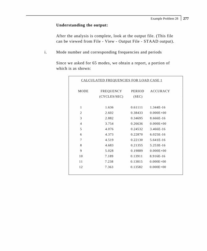
Example Problem 28 277
Understanding the output: After the analysis is complete, look at the output file. (This file can be viewed from File - View - Output File - STAAD output).
i. Mode number and corresponding frequencies and periods Since we asked for 65 modes, we obtain a report, a portion of which is as shown:
CALCULATED FREQUENCIES FOR LOAD CASE 1
MODE FREQUENCY PERIOD ACCURACY
(CYCLES/SEC) (SEC)
1 1.636 0.61111 1.344E-16
2 2.602 0.38433 0.000E+00
3 2.882 0.34695 8.666E-16
4 3.754 0.26636 0.000E+00
5 4.076 0.24532 3.466E-16
6 4.373 0.22870 6.025E-16
7 4.519 0.22130 5.641E-16
8 4.683 0.21355 5.253E-16
9 5.028 0.19889 0.000E+00
10 7.189 0.13911 8.916E-16
11 7.238 0.13815 0.000E+00
12 7.363 0.13582 0.000E+00

Part I - Application Examples
Example Problem 28 278
ii. Participation factors in Percentage
MASS PARTICIPATION FACTORS IN PERCENT
MODE X Y Z SUMM-X SUMM-Y SUMM-Z
1 0.01 0.00 99.04 0.012 0.000 99.042
2 99.14 0.00 0.02 99.151 0.000 99.061
3 0.00 0.23 0.00 99.151 0.229 99.062
4 0.00 3.27 0.00 99.151 3.496 99.062
5 0.00 0.04 0.05 99.151 3.536 99.112
6 0.05 0.04 0.02 99.202 3.575 99.135
7 0.00 26.42 0.00 99.204 30.000 99.135
8 0.00 25.59 0.00 99.204 55.587 99.136
9 0.53 0.15 0.19 99.735 55.740 99.326
10 0.00 0.13 0.00 99.736 55.871 99.326
11 0.00 0.06 0.00 99.736 55.927 99.326
12 0.00 0.04 0.00 99.736 55.969 99.326
In the explanation earlier for the CUT OFF MODE command, we said that one measure of the importance of a mode is the participation factor of that mode. We can see from the above report that for vibration along Z direction, the first mode has a 99.04 percent participation. It is also apparent that the 7th mode is primarily a Y direction mode with a 26.42 % participation along Y and 0 in X and Z. The SUMM-X, SUMM-Y and SUMM-Z columns show the cumulative value of the participation of all the modes upto and including a given mode. One can infer from those terms that if one is interested in 95% participation along X, the first 2 modes are sufficient. But for the Y direction, even with 10 modes, we barely obtained 60%. The reason for this can be understood by an examination of the nature of the structure. The deck slab is capable of vibrating in several low energy and primarily vertical direction modes. The out-of-plane flexible nature of the slab enables it to vibrate in a

Example Problem 28 279
manner resembling a series of wave like curves. Masses on either side of the equilibrium point have opposing eigenvector values leading to a lot of cancellation of the contribution from the respective masses. Localized modes, where small pockets in the structure undergo flutter due to their relative weak stiffness compared to the rest of the model, also result in small participation factors.
iii. Viewing the mode shapes After the analysis is completed, select Post-processing from the mode menu. This screen contains facilities for graphically examining the shape of the mode in static and animated views. The Dynamics page on the left side of the screen is available for viewing the shape of the mode statically. The Animation option of the Results menu can be used for animating the mode. The mode number can be selected from the “Loads and Results” tab of the “Diagrams” dialog box which comes up when the Animation option is chosen. The size to which the mode is drawn is controlled using the “Scales” tab of the “Diagrams” dialog box.

Part I - Application Examples
Example Problem 28 280
NOTES

Example Problem 29 281
Example Problem No. 29
Analysis and design of a structure for seismic loads is demonstrated in this example. The elaborate dynamic analysis procedure called time history analysis is used. In this model, static load cases are solved along with the seismic load case. For the seismic case, the maximum values of displacements, forces and reactions are obtained. The results of the dynamic case are combined with those of the static cases and steel design is performed on the combined cases.
3.50m
1.80m
1.70m
1.90m
3.00m
2.80m
1.80m
3.00m

Part I - Application Examples
Example Problem 29 282
Actual input is shown in bold lettering followed by explanation. STAAD SPACE DYNAMIC ANALYSIS FOR SEISMIC LOADS
Every STAAD input file has to begin with the word STAAD. The word SPACE signifies that the structure is a space frame and the geometry is defined through X, Y and Z axes. The remainder of the words form a title to identify this project.
UNIT METER KNS
The units for the data that follows are specified above.
JOINT COORDINATES 1 0 0 0 ; 2 0 3.5 0 ; 3 0 5.3 0 ; 4 0 7 0 REPEAT ALL 1 9.5 0 0 REPEAT ALL 1 0 0 3 17 1.8 7 0 ; 18 4.6 7 0 ; 19 7.6 7 0 REPEAT ALL 1 0 0 3
For joints 1 through 4, the joint number is followed by the X, Y and Z coordinates as specified above. The coordinates of these joints are used as a basis for generating 12 more joints by incrementing the X & Z coordinates by specific amounts. REPEAT ALL commands are used for the generation. Details of these commands are available in Section 5.11 of the Technical Reference manual. Following this, another round of explicit definition (joints 17, 18 & 19) and generation (20, 21 & 22) is carried out. The results of the generation may be visually verified using STAAD.Pro's graphical viewing facilities.
MEMBER INCIDENCES 1 1 2 3 REPEAT 1 3 4 7 9 10 9 10 13 14 12 13 4 17; 14 17 18; 15 18 19; 16 19 8 17 12 20; 18 20 21; 19 21 22; 20 22 16 21 2 10; 22 4 12; 23 6 14 24 8 16; 25 3 17; 26 7 19; 27 11 20; 28 15 22; 29 18 21

Example Problem 29 283
A mixture of explicit definition and generation of member connectivity data (joint numbers between which members are connected) is used to generate 29 members for the structure.
START GROUP DEFINITION MEMBER _VERTICAL 1 TO 12 _XBEAM 13 TO 20 _ZBEAM 21 TO 24 29 _BRACE 25 TO 28 END GROUP DEFINITION
The above block of data is referred to as formation of groups. Group names are a mechanism by which a single moniker can be used to refer to a cluster of entities, such as members. For our structure, the columns are being grouped to a name called VERTICAL, the beams running along the X direction are assigned the name XBEAM, and so on.
MEMBER PROPERTIES CANADIAN _VERTICAL TA ST W310X97 _XBEAM TA ST W250X39 _ZBEAM TA ST C200X17 _BRACE TA ST L152X152X13
Member properties are assigned from the Canadian steel table. The members which receive these properties are those embedded within the respective group names. The benefit of using the group name is apparent here. Just from the looks of the command, we can understand that the diagonal braces are being assigned a single angle. The alternative, which would be
25 TO 28 TA ST L152X152X13 would have required us to go to the graphical tools to get a sense of what members 25 to 28 are.
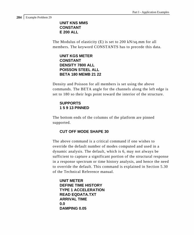
Part I - Application Examples
Example Problem 29 284 UNIT KNS MMS CONSTANT E 200 ALL
The Modulus of elasticity (E) is set to 200 kN/sq.mm for all members. The keyword CONSTANTS has to precede this data.
UNIT KGS METER CONSTANT DENSITY 7800 ALL POISSON STEEL ALL BETA 180 MEMB 21 22
Density and Poisson for all members is set using the above commands. The BETA angle for the channels along the left edge is set to 180 so their legs point toward the interior of the structure.
SUPPORTS 1 5 9 13 PINNED
The bottom ends of the columns of the platform are pinned supported.
CUT OFF MODE SHAPE 30 The above command is a critical command if one wishes to override the default number of modes computed and used in a dynamic analysis. The default, which is 6, may not always be sufficient to capture a significant portion of the structural response in a response spectrum or time history analysis, and hence the need to override the default. This command is explained in Section 5.30 of the Technical Reference manual.
UNIT METER DEFINE TIME HISTORY TYPE 1 ACCELERATION READ EQDATA.TXT ARRIVAL TIME 0.0 DAMPING 0.05

Example Problem 29 285
There are two stages in the command specification required for a time-history analysis. The first stage is defined above. Here, the parameters of the earthquake (ground acceleration) are provided. Each data set is individually identified by the number that follows the TYPE command. In this file, only one data set is defined, which is apparent from the fact that only one TYPE is defined. The word FORCE that follows the TYPE 1 command signifies that this data set is for a ground acceleration. (If one wishes to specify a forcing function, the keyword FORCE must be used instead.) Notice the expression "READ EQDATA.TXT". It means that we have chosen to specify the time vs. ground acceleration data in the file called EQDATA.TXT. That file must reside in the same folder as the one in which the data file for this structure resides. As explained in the small examples shown in Section 5.31.4 of the Technical Reference manual, the EQDATA.TXT file is a simple text file containing several pairs of time-acceleration data. A sample portion of that file is as shown below.
0.0000 0.006300 0.0200 0.003640 0.0400 0.000990 0.0600 0.004280 0.0800 0.007580 0.1000 0.010870
While it may not be apparent from the above numbers, it may also be noted that the geological data for the site the building sits on indicate that the above acceleration values are a fraction of "g", the acceleration due to gravity. Thus, for example, at 0.02 seconds, the acceleration is 0.00364 multiplied by 9.806 m/sec^2 (or 0.00364 multiplied by 32.2 ft/sec^2). Consequently, the burden of informing the program that the values need to be multiplied by "g" is upon us, and we shall be doing so at a later step.

Part I - Application Examples
Example Problem 29 286
The arrival time value indicates the relative value of time at which the earthquake begins to act upon the structure. We have chosen 0.0, as there is no other dynamic load on the structure from the relative time standpoint. The modal damping ratio for all the modes is set to 0.05.
LOAD 1 WEIGHT OF STRUCTURE ACTING STATICALLY SELFWEIGHT Y -1.0
The above data describe a static load case. The selfweight of the structure is acting in the negative global Y direction.
LOAD 2 PLATFORM LEVEL LOAD ACTING STATICALLY FLOOR LOAD YRA 6.9 7.1 FLOAD -500
Load case 2 is also a static load case. At the Y=7.0m elevation, our structure has a floor slab. But, it is a non-structural entity which, though capable of carrying the loads acting on itself, is not meant to be an integral part of the framing system. It merely transmits the load to the beam-column grid. There are uniform area loads on the floor (think of the load as wooden pallets supporting boxes of paper). Since the slab is not part of the structural model, how do we tell the program to transmit the imposed load from the slab to the beams without manually converting them to distributed beam loads ourselves? That is where the floor load utility comes in handy. It is a facility where we specify the load as a pressure, and the program converts the pressure to individual beam loads. Thus, the input required from the user is very simple - load intensity in the form of pressure, and the region of the structure in terms of X, Y and Z coordinates in space, of the area over which the pressure acts. In the process of converting the pressure to beam loads, STAAD will consider the empty space between criss-crossing beams (in plan view) to be panels, similar to the squares of a chess board. The load on each panel is then tranferred to beams surrounding the panel, using a triangular or trapezoidal load distribution method.

Example Problem 29 287
LOAD 3 DYNAMIC LOAD * MASSES SELFWEIGHT X 1.0 SELFWEIGHT Y 1.0 SELFWEIGHT Z 1.0 FLOOR LOAD YRANGE 6.9 7.1 FLOAD 500 GX YRANGE 6.9 7.1 FLOAD 500 GY YRANGE 6.9 7.1 FLOAD 500 GZ
Load case 3 is the dynamic load case, the one which contains the second part of the instruction set for a dynamic analysis to be performed. The data here are
a. loads which will yield the mass values which will populate the mass matrix
b. the directions of the loads, which will yield the degree of freedom numbers of the mass matrix for being populated.
Thus, the selfweight, as well as the imposed loads on the non-structural slab are to be considered as participating in the vibration along all the global directions.
GROUND MOTION X 1 1 9.806 The above command too is part of load case 3. Here we say that the seismic force, whose characteristics are defined by the TYPE 1 time history input data, acting at arrival time 1, is to be applied along the X direction. We mentioned earlier that the acceleration input data was specified as a fraction of “g”. The number 9.806 indicates the value which the accleration data, as read from EQDATA.TXT are to be factored by before they are used.

Part I - Application Examples
Example Problem 29 288 LOAD COMBINATION 11 (STATIC + POSITIVE OF DYNAMIC) 1 1.0 2 1.0 3 1.0 LOAD COMBINATION 12 (STATIC + NEGATIVE OF DYNAMIC) 1 1.0 2 1.0 3 -1.0
In a time history analysis, the member forces FX thru MZ each have a value for every time step. If there are a 1000 time steps, there will be 1000 values of FX, 1000 for FY etc. for that load case. Not all of them can be used in a further calculation like a steel or concrete design. However, the maximum from among those time steps is available. If we wish to do a design, one way to make sure that the structure is not under-designed is to create 2 load combination cases involving the dynamic case, a positive combination, and a negative combination. That is what is being done above. Load combination case no. 11 consists of the sum of the static load cases (1 & 2) with the positive direction of the dynamic load case (3). Load combination case no. 12 consists of the sum of the static load cases (1 & 2) with the negative direction of the dynamic load case (3). The user has discretion on what load factors to use with these combinations. We have chosen the factors to be 1.0.
PERFORM ANALYSIS The above is the instruction to perform the analysis related calculations. That means, computing nodal displacements, support reactions, etc.
PRINT ANALYSIS RESULTS The above command is an instruction to the program to produce a report of the joint displacements, support reactions and member end forces in the output file. As mentioned earlier, for the dynamic case, these will be just the maximum values, not the ones generated for every time step. If the user wishes to see the results for each time step, he/she may do so by using STAAD's Post-processing facilities.

Example Problem 29 289
LOAD LIST 11 12 PARAMETER CODE CANADA CHECK CODE ALL
A steel design - code check - is done according to the Canadian code for load cases 11 and 12.
FINISH

Part I - Application Examples
Example Problem 29 290 **************************************************** * * * STAAD.Pro * * Version 2007 Build 02 * * Proprietary Program of * * Research Engineers, Intl. * * Date= * * Time= * * * * USER ID: * **************************************************** 1. STAAD SPACE DYNAMIC ANALYSIS FOR SEISMIC LOADS 3. UNIT METER KNS 4. JOINT COORDINATES 5. 1 0 0 0 ; 2 0 3.5 0 ; 3 0 5.3 0 ; 4 0 7 0 6. REPEAT ALL 1 9.5 0 0 7. REPEAT ALL 1 0 0 3 8. 17 1.8 7 0 ; 18 4.6 7 0 ; 19 7.6 7 0 9. REPEAT ALL 1 0 0 3 11. MEMBER INCIDENCES 12. 1 1 2 3 13. REPEAT 1 3 4 14. 7 9 10 9 15. 10 13 14 12 16. 13 4 17; 14 17 18; 15 18 19; 16 19 8 17. 17 12 20; 18 20 21; 19 21 22; 20 22 16 18. 21 2 10; 22 4 12; 23 6 14 19. 24 8 16; 25 3 17; 26 7 19; 27 11 20; 28 15 22; 29 18 21 21. START GROUP DEFINITION 22. MEMBER 23. _VERTICAL 1 TO 12 24. _XBEAM 13 TO 20 25. _ZBEAM 21 TO 24 29 26. _BRACE 25 TO 28 27. END GROUP DEFINITION 29. MEMBER PROPERTIES CANADIAN 30. _VERTICAL TA ST W310X97 31. _XBEAM TA ST W250X39 32. _ZBEAM TA ST C200X17 33. _BRACE TA ST L152X152X13 35. UNIT KNS MMS 36. CONSTANT 37. E 200 ALL 39. UNIT KGS METER 40. CONSTANT 41. DENSITY 7800 ALL 42. POISSON STEEL ALL 43. BETA 180 MEMB 21 22 45. SUPPORTS 46. 1 5 9 13 PINNED 48. CUT OFF MODE SHAPE 30 51. UNIT METER 52. DEFINE TIME HISTORY 53. TYPE 1 ACCELERATION 54. READ EQDATA.TXT 55. ARRIVAL TIME 56. 0.0 57. DAMPING 0.05 60. LOAD 1 WEIGHT OF STRUCTURE ACTING STATICALLY 61. SELFWEIGHT Y -1.0 63. LOAD 2 PLATFORM LEVEL LOAD ACTING STATICALLY 64. FLOOR LOAD 65. YRA 6.9 7.1 FLOAD -500 **WARNING** about Floor/OneWay Loads/Weights. Please note that depending on the shape of the floor you may have to break up the FLOOR/ONEWAY LOAD into multiple commands. For details please refer to Technical Reference Manual Section 5.32.4 Note 6.

Example Problem 29 291 67. LOAD 3 DYNAMIC LOAD 68. * MASSES 69. SELFWEIGHT X 1.0 70. SELFWEIGHT Y 1.0 71. SELFWEIGHT Z 1.0 73. FLOOR LOAD 74. YRANGE 6.9 7.1 FLOAD 500 GX 75. YRANGE 6.9 7.1 FLOAD 500 GY 76. YRANGE 6.9 7.1 FLOAD 500 GZ 78. GROUND MOTION X 1 1 9.806 80. LOAD COMBINATION 11 (STATIC + POSITIVE OF DYNAMIC) 81. 1 1.0 2 1.0 3 1.0 83. LOAD COMBINATION 12 (STATIC + NEGATIVE OF DYNAMIC) 84. 1 1.0 2 1.0 3 -1.0 86. PERFORM ANALYSIS P R O B L E M S T A T I S T I C S ----------------------------------- NUMBER OF JOINTS/MEMBER+ELEMENTS/SUPPORTS = 22/ 29/ 4 SOLVER USED IS THE IN-CORE ADVANCED SOLVER TOTAL PRIMARY LOAD CASES = 3, TOTAL DEGREES OF FREEDOM = 120 NUMBER OF MODES REQUESTED = 30 NUMBER OF EXISTING MASSES IN THE MODEL = 54 NUMBER OF MODES THAT WILL BE USED = 30 *** EIGENSOLUTION: ADVANCED METHOD *** CALCULATED FREQUENCIES FOR LOAD CASE 3 MODE FREQUENCY(CYCLES/SEC) PERIOD(SEC) 1 0.693 1.44201 2 1.224 0.81697 3 1.370 0.73010 4 1.567 0.63818 5 2.082 0.48034 6 3.047 0.32823 7 4.220 0.23695 8 4.281 0.23360 9 5.553 0.18008 10 5.559 0.17990 11 5.736 0.17433 12 12.880 0.07764 13 12.888 0.07759 14 15.228 0.06567 15 15.285 0.06542 16 16.567 0.06036 17 16.574 0.06034 18 45.644 0.02191 19 45.667 0.02190 20 49.158 0.02034 21 49.187 0.02033 22 52.323 0.01911 23 52.470 0.01906 24 54.972 0.01819 25 56.110 0.01782 26 56.126 0.01782 27 65.939 0.01517 28 66.102 0.01513 29 87.835 0.01139 30 88.053 0.01136

Part I - Application Examples
Example Problem 29 292 PARTICIPATION FACTORS MASS PARTICIPATION FACTORS IN PERCENT -------------------------------------- MODE X Y Z SUMM-X SUMM-Y SUMM-Z 1 0.00 0.00 85.38 0.000 0.000 85.379 2 98.05 0.00 0.00 98.051 0.000 85.379 3 0.00 0.00 0.01 98.051 0.000 85.384 4 0.00 0.00 0.03 98.051 0.000 85.411 5 0.00 0.00 13.41 98.051 0.000 98.816 6 0.00 0.00 0.00 98.051 0.000 98.816 7 0.00 0.00 0.00 98.051 0.000 98.816 8 0.00 0.00 0.01 98.051 0.000 98.827 9 0.00 51.86 0.00 98.051 51.860 98.827 10 0.00 0.00 0.00 98.051 51.860 98.829 11 0.00 0.00 0.23 98.051 51.860 99.059 12 1.68 0.25 0.00 99.731 52.110 99.059 13 0.00 0.00 0.00 99.731 52.110 99.059 14 0.00 0.00 0.39 99.731 52.110 99.453 15 0.00 0.00 0.52 99.731 52.110 99.977 16 0.03 7.02 0.00 99.761 59.126 99.977 17 0.00 0.00 0.00 99.761 59.126 99.977 18 0.00 10.52 0.00 99.762 69.646 99.977 19 0.00 0.00 0.00 99.762 69.646 99.977 20 0.23 0.06 0.00 99.991 69.706 99.977 21 0.00 0.00 0.00 99.991 69.706 99.977 22 0.00 0.00 0.00 99.991 69.706 99.977 23 0.00 0.00 0.00 99.991 69.706 99.977 24 0.00 0.00 0.00 99.991 69.706 99.977 25 0.00 2.48 0.00 99.991 72.186 99.977 26 0.00 0.00 0.00 99.991 72.186 99.977 27 0.00 0.00 0.01 99.991 72.186 99.989 28 0.00 0.00 0.01 99.991 72.186 100.000 29 0.00 0.00 0.00 99.991 72.186 100.000 30 0.00 9.74 0.00 99.995 81.929 100.000 A C T U A L MODAL D A M P I N G USED IN ANALYSIS MODE DAMPING 1 0.0500 2 0.0500 3 0.0500 4 0.0500 5 0.0500 6 0.0500 7 0.0500 8 0.0500 9 0.0500 10 0.0500 11 0.0500 12 0.0500 13 0.0500 14 0.0500 15 0.0500 16 0.0500 17 0.0500 18 0.0500 19 0.0500 20 0.0500 21 0.0500 22 0.0500 23 0.0500 24 0.0500 25 0.0500 26 0.0500 27 0.0500 28 0.0500 29 0.0500 30 0.0500

Example Problem 29 293 TIME STEP USED IN TIME HISTORY ANALYSIS = 0.00139 SECONDS NUMBER OF MODES WHOSE CONTRIBUTION IS CONSIDERED = 30 TIME DURATION OF TIME HISTORY ANALYSIS = 31.160 SECONDS NUMBER OF TIME STEPS IN THE SOLUTION PROCESS = 22435 BASE SHEAR UNITS ARE -- KGS METE MAXIMUM BASE SHEAR X= -9.249217E+03 Y= -5.280383E+01 Z= 1.275646E-06 AT TIMES 5.802778 2.445833 2.380556 87. PRINT ANALYSIS RESULTS JOINT DISPLACEMENT (CM RADIANS) STRUCTURE TYPE = SPACE ------------------ JOINT LOAD X-TRANS Y-TRANS Z-TRANS X-ROTAN Y-ROTAN Z-ROTAN 1 1 0.0000 0.0000 0.0000 0.0000 0.0000 0.0001 2 0.0000 0.0000 0.0000 0.0000 0.0000 0.0015 3 0.0000 0.0000 0.0000 0.0000 0.0000 -0.0167 11 0.0000 0.0000 0.0000 0.0000 0.0000 -0.0151 12 0.0000 0.0000 0.0000 0.0000 0.0000 0.0184 2 1 -0.0283 -0.0011 0.0000 0.0000 0.0000 0.0000 2 -0.4133 -0.0050 -0.0004 -0.0001 0.0000 0.0004 3 5.5307 0.0045 0.0000 0.0000 0.0000 -0.0136 11 5.0891 -0.0016 -0.0005 -0.0001 0.0000 -0.0133 12 -5.9724 -0.0106 -0.0005 -0.0001 0.0000 0.0140 3 1 -0.0242 -0.0015 -0.0002 0.0000 0.0000 -0.0001 2 -0.3559 -0.0075 -0.0122 0.0000 -0.0001 -0.0012 3 7.6673 0.0068 0.0000 0.0000 0.0000 -0.0097 11 7.2871 -0.0022 -0.0124 0.0000 -0.0001 -0.0109 12 -8.0475 -0.0159 -0.0124 0.0000 -0.0001 0.0084 4 1 -0.0029 -0.0016 0.0000 0.0000 0.0000 -0.0001 2 -0.0438 -0.0076 0.0004 0.0002 0.0000 -0.0020 3 9.0199 0.0025 0.0000 0.0000 0.0000 -0.0079 11 8.9732 -0.0067 0.0004 0.0002 0.0000 -0.0100 12 -9.0665 -0.0117 0.0004 0.0002 0.0000 0.0058 5 1 0.0000 0.0000 0.0000 0.0000 0.0000 -0.0001 2 0.0000 0.0000 0.0000 0.0000 0.0000 -0.0014 3 0.0000 0.0000 0.0000 0.0000 0.0000 -0.0168 11 0.0000 0.0000 0.0000 0.0000 0.0000 -0.0183 12 0.0000 0.0000 0.0000 0.0000 0.0000 0.0153 6 1 0.0256 -0.0011 0.0000 0.0000 0.0000 0.0000 2 0.3722 -0.0050 -0.0004 -0.0001 0.0000 -0.0002 3 5.5469 -0.0045 0.0000 0.0000 0.0000 -0.0136 11 5.9447 -0.0106 -0.0005 -0.0001 0.0000 -0.0139 12 -5.1491 -0.0016 -0.0005 -0.0001 0.0000 0.0134 7 1 0.0201 -0.0015 -0.0002 0.0000 0.0000 0.0001 2 0.2936 -0.0075 -0.0122 0.0000 0.0001 0.0013 3 7.6810 -0.0068 0.0000 0.0000 0.0000 -0.0096 11 7.9947 -0.0159 -0.0124 0.0000 0.0001 -0.0082 12 -7.3672 -0.0023 -0.0124 0.0000 0.0001 0.0110 8 1 -0.0026 -0.0016 0.0000 0.0000 0.0000 0.0001 2 -0.0387 -0.0077 0.0004 0.0002 0.0000 0.0021 3 9.0211 -0.0027 0.0000 0.0000 0.0000 -0.0078 11 8.9799 -0.0120 0.0004 0.0002 0.0000 -0.0056 12 -9.0624 -0.0066 0.0004 0.0002 0.0000 0.0101 9 1 0.0000 0.0000 0.0000 0.0000 0.0000 0.0001 2 0.0000 0.0000 0.0000 0.0000 0.0000 0.0015 3 0.0000 0.0000 0.0000 0.0000 0.0000 -0.0167 11 0.0000 0.0000 0.0000 0.0000 0.0000 -0.0151 12 0.0000 0.0000 0.0000 0.0000 0.0000 0.0184 10 1 -0.0283 -0.0011 0.0000 0.0000 0.0000 0.0000 2 -0.4133 -0.0050 0.0004 0.0001 0.0000 0.0004 3 5.5307 0.0045 0.0000 0.0000 0.0000 -0.0136 11 5.0891 -0.0016 0.0005 0.0001 0.0000 -0.0133 12 -5.9724 -0.0106 0.0005 0.0001 0.0000 0.0140 11 1 -0.0242 -0.0015 0.0002 0.0000 0.0000 -0.0001 2 -0.3559 -0.0075 0.0122 0.0000 0.0001 -0.0012 3 7.6673 0.0068 0.0000 0.0000 0.0000 -0.0097 11 7.2871 -0.0022 0.0124 0.0000 0.0001 -0.0109 12 -8.0475 -0.0159 0.0124 0.0000 0.0001 0.0084

Part I - Application Examples
Example Problem 29 294 JOINT DISPLACEMENT (CM RADIANS) STRUCTURE TYPE = SPACE ------------------ JOINT LOAD X-TRANS Y-TRANS Z-TRANS X-ROTAN Y-ROTAN Z-ROTAN 12 1 -0.0029 -0.0016 0.0000 0.0000 0.0000 -0.0001 2 -0.0438 -0.0076 -0.0004 -0.0002 0.0000 -0.0020 3 9.0199 0.0025 0.0000 0.0000 0.0000 -0.0079 11 8.9732 -0.0067 -0.0004 -0.0002 0.0000 -0.0100 12 -9.0665 -0.0117 -0.0004 -0.0002 0.0000 0.0058 13 1 0.0000 0.0000 0.0000 0.0000 0.0000 -0.0001 2 0.0000 0.0000 0.0000 0.0000 0.0000 -0.0014 3 0.0000 0.0000 0.0000 0.0000 0.0000 -0.0168 11 0.0000 0.0000 0.0000 0.0000 0.0000 -0.0183 12 0.0000 0.0000 0.0000 0.0000 0.0000 0.0153 14 1 0.0256 -0.0011 0.0000 0.0000 0.0000 0.0000 2 0.3722 -0.0050 0.0004 0.0001 0.0000 -0.0002 3 5.5469 -0.0045 0.0000 0.0000 0.0000 -0.0136 11 5.9447 -0.0106 0.0005 0.0001 0.0000 -0.0139 12 -5.1491 -0.0016 0.0005 0.0001 0.0000 0.0134 15 1 0.0201 -0.0015 0.0002 0.0000 0.0000 0.0001 2 0.2936 -0.0075 0.0122 0.0000 -0.0001 0.0013 3 7.6810 -0.0068 0.0000 0.0000 0.0000 -0.0096 11 7.9947 -0.0159 0.0124 0.0000 -0.0001 -0.0082 12 -7.3672 -0.0023 0.0124 0.0000 -0.0001 0.0110 16 1 -0.0026 -0.0016 0.0000 0.0000 0.0000 0.0001 2 -0.0387 -0.0077 -0.0004 -0.0002 0.0000 0.0021 3 9.0211 -0.0027 0.0000 0.0000 0.0000 -0.0078 11 8.9799 -0.0120 -0.0004 -0.0002 0.0000 -0.0056 12 -9.0624 -0.0066 -0.0004 -0.0002 0.0000 0.0101 17 1 -0.0026 -0.0261 0.0000 0.0000 0.0000 -0.0002 2 -0.0388 -0.3675 0.0008 0.0001 0.0000 -0.0025 3 9.0035 -1.3394 0.0000 0.0000 0.0000 -0.0033 11 8.9621 -1.7331 0.0008 0.0001 0.0000 -0.0059 12 -9.0449 0.9458 0.0008 0.0001 0.0000 0.0007 18 1 -0.0027 -0.0630 0.0000 0.0001 0.0000 0.0000 2 -0.0412 -0.9611 0.0000 0.0038 0.0000 -0.0003 3 9.0055 -0.0712 0.0000 0.0000 0.0000 0.0083 11 8.9615 -1.0952 0.0000 0.0039 0.0000 0.0080 12 -9.0494 -0.9529 0.0000 0.0039 0.0000 -0.0086 19 1 -0.0029 -0.0289 0.0000 0.0000 0.0000 0.0002 2 -0.0438 -0.4095 0.0009 0.0001 0.0000 0.0025 3 9.0035 1.3991 0.0000 0.0000 0.0000 -0.0031 11 8.9568 0.9607 0.0009 0.0001 0.0000 -0.0004 12 -9.0503 -1.8375 0.0009 0.0001 0.0000 0.0057 20 1 -0.0026 -0.0261 0.0000 0.0000 0.0000 -0.0002 2 -0.0388 -0.3675 -0.0008 -0.0001 0.0000 -0.0025 3 9.0035 -1.3394 0.0000 0.0000 0.0000 -0.0033 11 8.9621 -1.7331 -0.0008 -0.0001 0.0000 -0.0059 12 -9.0449 0.9458 -0.0008 -0.0001 0.0000 0.0007 21 1 -0.0027 -0.0630 0.0000 -0.0001 0.0000 0.0000 2 -0.0412 -0.9611 0.0000 -0.0038 0.0000 -0.0003 3 9.0055 -0.0712 0.0000 0.0000 0.0000 0.0083 11 8.9615 -1.0952 0.0000 -0.0039 0.0000 0.0080 12 -9.0494 -0.9529 0.0000 -0.0039 0.0000 -0.0086 22 1 -0.0029 -0.0289 0.0000 0.0000 0.0000 0.0002 2 -0.0438 -0.4095 -0.0009 -0.0001 0.0000 0.0025 3 9.0035 1.3991 0.0000 0.0000 0.0000 -0.0031 11 8.9568 0.9607 -0.0009 -0.0001 0.0000 -0.0004 12 -9.0503 -1.8375 -0.0009 -0.0001 0.0000 0.0057 SUPPORT REACTIONS -UNIT KGS METE STRUCTURE TYPE = SPACE ----------------- JOINT LOAD FORCE-X FORCE-Y FORCE-Z MOM-X MOM-Y MOM Z 1 1 60.22 989.78 0.96 0.00 0.00 0.00 2 873.60 3562.50 -19.74 0.00 0.00 0.00 3 -2294.73 -3225.14 0.00 0.00 0.00 0.00 11 -1360.90 1327.14 -18.78 0.00 0.00 0.00 12 3228.55 7777.43 -18.78 0.00 0.00 0.00

Example Problem 29 295 SUPPORT REACTIONS -UNIT KGS METE STRUCTURE TYPE = SPACE ----------------- JOINT LOAD FORCE-X FORCE-Y FORCE-Z MOM-X MOM-Y MOM Z 5 1 -60.22 989.93 0.96 0.00 0.00 0.00 2 -873.60 3562.50 -19.74 0.00 0.00 0.00 3 -2329.88 3221.91 0.00 0.00 0.00 0.00 11 -3263.71 7774.34 -18.78 0.00 0.00 0.00 12 1396.06 1330.52 -18.78 0.00 0.00 0.00 9 1 60.22 989.78 -0.96 0.00 0.00 0.00 2 873.60 3562.50 19.74 0.00 0.00 0.00 3 -2294.73 -3225.14 0.00 0.00 0.00 0.00 11 -1360.90 1327.14 18.78 0.00 0.00 0.00 12 3228.55 7777.43 18.78 0.00 0.00 0.00 13 1 -60.22 989.93 -0.96 0.00 0.00 0.00 2 -873.60 3562.50 19.74 0.00 0.00 0.00 3 -2329.88 3221.91 0.00 0.00 0.00 0.00 11 -3263.71 7774.34 18.78 0.00 0.00 0.00 12 1396.06 1330.52 18.78 0.00 0.00 0.00 MEMBER END FORCES STRUCTURE TYPE = SPACE ----------------- ALL UNITS ARE -- KGS METE (LOCAL ) MEMBER LOAD JT AXIAL SHEAR-Y SHEAR-Z TORSION MOM-Y MOM-Z 1 1 1 989.78 -60.22 0.96 0.00 0.00 0.00 2 -653.99 60.22 -0.96 0.00 -3.36 -210.78 2 1 3562.50 -873.60 -19.74 0.00 0.00 0.00 2 -3562.50 873.60 19.74 0.00 69.09 -3057.61 3 1 -3225.14 2294.73 0.00 0.00 0.00 0.00 2 3225.14 -2294.73 0.00 0.00 0.00 8031.54 11 1 1327.14 1360.90 -18.78 0.00 0.00 0.00 2 -991.35 -1360.90 18.78 0.00 65.73 4763.16 12 1 7777.43 -3228.55 -18.78 0.00 0.00 0.00 2 -7441.64 3228.55 18.78 0.00 65.73 -11299.93 2 1 2 628.60 -60.22 5.86 0.01 -8.86 210.78 3 -455.91 60.22 -5.86 -0.01 -1.69 -319.18 2 2 3562.50 -873.60 112.31 0.22 -79.35 3057.61 3 -3562.50 873.60 -112.31 -0.22 -122.81 -4630.10 3 2 -3225.15 2195.71 0.00 0.00 0.00 -8031.54 3 3225.15 -2195.71 0.00 0.00 0.00 11983.79 11 2 965.95 1261.88 118.17 0.23 -88.20 -4763.16 3 -793.26 -1261.88 -118.17 -0.23 -124.50 7034.51 12 2 7416.26 -3129.53 118.17 0.23 -88.20 11299.93 3 -7243.56 3129.53 -118.17 -0.23 -124.50 -16933.06 3 1 3 187.97 179.52 5.85 -0.01 1.67 298.15 4 -24.88 -179.52 -5.85 0.01 -11.61 7.04 2 3 56.29 2785.04 111.62 -0.33 122.15 4496.67 4 -56.29 -2785.04 -111.62 0.33 -311.90 237.90 3 3 6354.83 -8591.51 0.00 0.00 0.00 -12019.14 4 -6354.83 8591.51 0.00 0.00 0.00 -2586.45 11 3 6599.09 -5626.95 117.47 -0.34 123.83 -7224.32 4 -6435.99 5626.95 -117.47 0.34 -323.52 -2341.51 12 3 -6110.57 11556.08 117.47 -0.34 123.83 16813.97 4 6273.67 -11556.08 -117.47 0.34 -323.52 2831.39 4 1 5 989.93 60.22 0.96 0.00 0.00 0.00 6 -654.14 -60.22 -0.96 0.00 -3.36 210.78 2 5 3562.50 873.60 -19.74 0.00 0.00 0.00 6 -3562.50 -873.60 19.74 0.00 69.08 3057.61 3 5 3221.91 2329.88 0.00 0.00 0.00 0.00 6 -3221.91 -2329.88 0.00 0.00 0.00 8154.58 11 5 7774.34 3263.71 -18.78 0.00 0.00 0.00 6 -7438.55 -3263.71 18.78 0.00 65.72 11422.97 12 5 1330.52 -1396.06 -18.78 0.00 0.00 0.00 6 -994.73 1396.06 18.78 0.00 65.72 -4886.20

Part I - Application Examples
Example Problem 29 296 MEMBER END FORCES STRUCTURE TYPE = SPACE ----------------- ALL UNITS ARE -- KGS METE (LOCAL ) MEMBER LOAD JT AXIAL SHEAR-Y SHEAR-Z TORSION MOM-Y MOM-Z 5 1 6 628.75 60.22 5.86 -0.01 -8.86 -210.78 7 -456.06 -60.22 -5.86 0.01 -1.69 319.18 2 6 3562.50 873.60 112.27 -0.21 -79.33 -3057.61 7 -3562.50 -873.60 -112.27 0.21 -122.76 4630.10 3 6 3221.81 2230.25 0.00 0.00 0.00 -8154.58 7 -3221.81 -2230.25 0.00 0.00 0.00 12168.93 11 6 7413.06 3164.08 118.13 -0.22 -88.19 -11422.97 7 -7240.36 -3164.08 -118.13 0.22 -124.45 17118.20 12 6 969.44 -1296.43 118.13 -0.22 -88.19 4886.20 7 -796.75 1296.43 -118.13 0.22 -124.45 -7219.66 6 1 7 201.36 -175.80 5.85 0.01 1.67 -296.62 8 -38.27 175.80 -5.85 -0.01 -11.61 -2.23 2 7 261.23 -2741.58 111.62 0.31 122.16 -4487.62 8 -261.23 2741.58 -111.62 -0.31 -311.91 -173.07 3 7 -6030.00 -8753.57 0.00 0.00 0.00 -12207.02 8 6030.00 8753.57 0.00 0.00 0.00 -2674.35 11 7 -5567.41 -11670.94 117.46 0.32 123.84 -16991.27 8 5730.51 11670.94 -117.46 -0.32 -323.52 -2849.65 12 7 6492.59 5836.19 117.46 0.32 123.84 7422.78 8 -6329.49 -5836.19 -117.46 -0.32 -323.52 2499.06 7 1 9 989.78 -60.22 -0.96 0.00 0.00 0.00 10 -653.99 60.22 0.96 0.00 3.36 -210.78 2 9 3562.50 -873.60 19.74 0.00 0.00 0.00 10 -3562.50 873.60 -19.74 0.00 -69.09 -3057.61 3 9 -3225.14 2294.73 0.00 0.00 0.00 0.00 10 3225.14 -2294.73 0.00 0.00 0.00 8031.54 11 9 1327.14 1360.90 18.78 0.00 0.00 0.00 10 -991.35 -1360.90 -18.78 0.00 -65.73 4763.16 12 9 7777.43 -3228.55 18.78 0.00 0.00 0.00 10 -7441.64 3228.55 -18.78 0.00 -65.73 -11299.93 8 1 10 628.60 -60.22 -5.86 -0.01 8.86 210.78 11 -455.91 60.22 5.86 0.01 1.69 -319.18 2 10 3562.50 -873.60 -112.31 -0.22 79.35 3057.61 11 -3562.50 873.60 112.31 0.22 122.81 -4630.10 3 10 -3225.15 2195.71 0.00 0.00 0.00 -8031.54 11 3225.15 -2195.71 0.00 0.00 0.00 11983.79 11 10 965.95 1261.88 -118.17 -0.23 88.20 -4763.16 11 -793.26 -1261.88 118.17 0.23 124.50 7034.51 12 10 7416.26 -3129.53 -118.17 -0.23 88.20 11299.93 11 -7243.56 3129.53 118.17 0.23 124.50 -16933.06 9 1 11 187.97 179.52 -5.85 0.01 -1.67 298.15 12 -24.88 -179.52 5.85 -0.01 11.61 7.04 2 11 56.29 2785.04 -111.62 0.33 -122.15 4496.67 12 -56.29 -2785.04 111.62 -0.33 311.90 237.90 3 11 6354.83 -8591.51 0.00 0.00 0.00 -12019.14 12 -6354.83 8591.51 0.00 0.00 0.00 -2586.45 11 11 6599.09 -5626.95 -117.47 0.34 -123.83 -7224.32 12 -6435.99 5626.95 117.47 -0.34 323.52 -2341.51 12 11 -6110.57 11556.08 -117.47 0.34 -123.83 16813.97 12 6273.67 -11556.08 117.47 -0.34 323.52 2831.39 10 1 13 989.93 60.22 -0.96 0.00 0.00 0.00 14 -654.14 -60.22 0.96 0.00 3.36 210.78 2 13 3562.50 873.60 19.74 0.00 0.00 0.00 14 -3562.50 -873.60 -19.74 0.00 -69.08 3057.61 3 13 3221.91 2329.88 0.00 0.00 0.00 0.00 14 -3221.91 -2329.88 0.00 0.00 0.00 8154.58 11 13 7774.34 3263.71 18.78 0.00 0.00 0.00 14 -7438.55 -3263.71 -18.78 0.00 -65.72 11422.97 12 13 1330.52 -1396.06 18.78 0.00 0.00 0.00 14 -994.73 1396.06 -18.78 0.00 -65.72 -4886.20

Example Problem 29 297 MEMBER END FORCES STRUCTURE TYPE = SPACE ----------------- ALL UNITS ARE -- KGS METE (LOCAL ) MEMBER LOAD JT AXIAL SHEAR-Y SHEAR-Z TORSION MOM-Y MOM-Z 11 1 14 628.75 60.22 -5.86 0.01 8.86 -210.78 15 -456.06 -60.22 5.86 -0.01 1.69 319.18 2 14 3562.50 873.60 -112.27 0.21 79.33 -3057.61 15 -3562.50 -873.60 112.27 -0.21 122.76 4630.10 3 14 3221.81 2230.25 0.00 0.00 0.00 -8154.58 15 -3221.81 -2230.25 0.00 0.00 0.00 12168.93 11 14 7413.06 3164.08 -118.13 0.22 88.19 -11422.97 15 -7240.36 -3164.08 118.13 -0.22 124.45 17118.20 12 14 969.44 -1296.43 -118.13 0.22 88.19 4886.20 15 -796.75 1296.43 118.13 -0.22 124.45 -7219.66 12 1 15 201.36 -175.80 -5.85 -0.01 -1.67 -296.62 16 -38.27 175.80 5.85 0.01 11.61 -2.23 2 15 261.23 -2741.58 -111.62 -0.31 -122.16 -4487.62 16 -261.23 2741.58 111.62 0.31 311.91 -173.07 3 15 -6030.00 -8753.57 0.00 0.00 0.00 -12207.02 16 6030.00 8753.57 0.00 0.00 0.00 -2674.35 11 15 -5567.41 -11670.94 -117.46 -0.32 -123.84 -16991.27 16 5730.51 11670.94 117.46 0.32 323.52 -2849.65 12 15 6492.59 5836.19 -117.46 -0.32 -123.84 7422.78 16 -6329.49 -5836.19 117.46 0.32 323.52 2499.06 13 1 4 -179.52 -0.51 -0.01 0.00 -0.01 -7.04 17 179.52 69.59 0.01 0.00 0.03 -56.05 2 4 -2785.04 -506.21 -0.70 0.08 -0.27 -237.90 17 2785.04 1293.71 0.70 -0.08 1.54 -1157.03 3 4 9119.87 6354.47 0.00 0.00 0.00 2586.45 17 -9119.87 -6354.47 0.00 0.00 0.00 8851.60 11 4 6155.30 5847.75 -0.71 0.09 -0.28 2341.51 17 -6155.30 -4991.17 0.71 -0.09 1.57 7638.51 12 4 -12084.44 -6861.20 -0.71 0.09 -0.28 -2831.39 17 12084.44 7717.78 0.71 -0.09 1.57 -10064.69 14 1 17 60.22 126.89 0.00 -0.03 0.01 66.67 18 -60.22 -19.44 0.00 0.03 -0.01 138.20 2 17 873.60 2212.50 -0.01 -1.76 0.26 1198.97 18 -873.60 -675.00 0.01 1.76 -0.24 2337.28 3 17 -707.62 -3344.18 0.00 0.00 0.00 -9748.53 18 707.62 3344.18 0.00 0.00 0.00 385.43 11 17 226.20 -1004.78 -0.01 -1.79 0.27 -8482.89 18 -226.20 2649.74 0.01 1.79 -0.24 2860.91 12 17 1641.45 5683.57 -0.01 -1.79 0.27 11014.17 18 -1641.45 -4038.62 0.01 1.79 -0.24 2090.04 15 1 18 60.22 -5.95 0.00 0.03 0.01 -138.20 19 -60.22 121.08 0.00 -0.03 -0.01 -52.34 2 18 873.60 -450.00 0.01 1.64 0.24 -2337.28 19 -873.60 2137.50 -0.01 -1.64 -0.26 -981.47 3 18 651.61 -3354.44 0.00 0.00 0.00 -385.43 19 -651.61 3354.44 0.00 0.00 0.00 -9678.42 11 18 1585.43 -3810.39 0.01 1.67 0.24 -2860.91 19 -1585.43 5613.02 -0.01 -1.67 -0.26 -10712.23 12 18 282.22 2898.49 0.01 1.67 0.24 -2090.04 19 -282.22 -1095.86 -0.01 -1.67 -0.26 8644.60 16 1 19 -175.80 60.04 0.01 0.00 -0.03 42.58 8 175.80 12.88 -0.01 0.00 0.01 2.23 2 19 -2741.58 1163.77 0.67 -0.08 -1.52 965.60 8 2741.58 -301.27 -0.67 0.08 0.25 173.07 3 19 -9298.97 6030.38 0.00 0.00 0.00 8783.37 8 9298.97 -6030.38 0.00 0.00 0.00 2674.35 11 19 -12216.35 7254.19 0.68 -0.08 -1.54 9791.55 8 12216.35 -6318.78 -0.68 0.08 0.26 2849.65 12 19 6381.59 -4806.57 0.68 -0.08 -1.54 -7775.19 8 -6381.59 5741.98 -0.68 0.08 0.26 -2499.06

Part I - Application Examples
Example Problem 29 298 MEMBER END FORCES STRUCTURE TYPE = SPACE ----------------- ALL UNITS ARE -- KGS METE (LOCAL ) MEMBER LOAD JT AXIAL SHEAR-Y SHEAR-Z TORSION MOM-Y MOM-Z 17 1 12 -179.52 -0.51 0.01 0.00 0.01 -7.04 20 179.52 69.59 -0.01 0.00 -0.03 -56.05 2 12 -2785.04 -506.21 0.70 -0.08 0.27 -237.90 20 2785.04 1293.71 -0.70 0.08 -1.54 -1157.03 3 12 9119.86 6354.47 0.00 0.00 0.00 2586.45 20 -9119.86 -6354.47 0.00 0.00 0.00 8851.60 11 12 6155.29 5847.75 0.71 -0.09 0.28 2341.51 20 -6155.29 -4991.17 -0.71 0.09 -1.57 7638.51 12 12 -12084.43 -6861.20 0.71 -0.09 0.28 -2831.39 20 12084.43 7717.78 -0.71 0.09 -1.57 -10064.69 18 1 20 60.22 126.89 0.00 0.03 -0.01 66.67 21 -60.22 -19.44 0.00 -0.03 0.01 138.20 2 20 873.60 2212.50 0.01 1.76 -0.26 1198.97 21 -873.60 -675.00 -0.01 -1.76 0.24 2337.28 3 20 -707.62 -3344.18 0.00 0.00 0.00 -9748.53 21 707.62 3344.18 0.00 0.00 0.00 385.43 11 20 226.21 -1004.78 0.01 1.79 -0.27 -8482.89 21 -226.21 2649.74 -0.01 -1.79 0.24 2860.91 12 20 1641.44 5683.57 0.01 1.79 -0.27 11014.17 21 -1641.44 -4038.62 -0.01 -1.79 0.24 2090.04 19 1 21 60.22 -5.95 0.00 -0.03 -0.01 -138.20 22 -60.22 121.08 0.00 0.03 0.01 -52.34 2 21 873.60 -450.00 -0.01 -1.64 -0.24 -2337.28 22 -873.60 2137.50 0.01 1.64 0.26 -981.47 3 21 651.61 -3354.44 0.00 0.00 0.00 -385.43 22 -651.61 3354.44 0.00 0.00 0.00 -9678.42 11 21 1585.43 -3810.39 -0.01 -1.67 -0.24 -2860.91 22 -1585.43 5613.02 0.01 1.67 0.26 -10712.23 12 21 282.22 2898.49 -0.01 -1.67 -0.24 -2090.04 22 -282.22 -1095.86 0.01 1.67 0.26 8644.60 20 1 22 -175.80 60.04 -0.01 0.00 0.03 42.58 16 175.80 12.88 0.01 0.00 -0.01 2.23 2 22 -2741.58 1163.77 -0.67 0.08 1.52 965.60 16 2741.58 -301.27 0.67 -0.08 -0.25 173.07 3 22 -9298.97 6030.38 0.00 0.00 0.00 8783.37 16 9298.97 -6030.38 0.00 0.00 0.00 2674.35 11 22 -12216.35 7254.19 -0.68 0.08 1.54 9791.55 16 12216.35 -6318.78 0.68 -0.08 -0.26 2849.65 12 22 6381.59 -4806.57 -0.68 0.08 1.54 -7775.19 16 -6381.59 5741.98 0.68 -0.08 -0.26 -2499.06 21 1 2 -4.90 -25.39 0.00 0.00 0.01 -12.22 10 4.90 -25.39 0.00 0.00 -0.01 12.22 2 2 -132.05 0.00 0.00 0.00 0.22 -10.26 10 132.05 0.00 0.00 0.00 -0.22 10.26 3 2 0.00 0.00 0.00 0.00 0.00 0.00 10 0.00 0.00 0.00 0.00 0.00 0.00 11 2 -136.96 -25.39 0.00 0.00 0.23 -22.48 10 136.96 -25.39 0.00 0.00 -0.23 22.48 12 2 -136.95 -25.39 0.00 0.00 0.23 -22.48 10 136.95 -25.39 0.00 0.00 -0.23 22.48 22 1 4 5.86 -25.39 0.00 0.00 0.00 -11.62 12 -5.86 -25.39 0.00 0.00 0.00 11.62 2 4 112.32 -562.50 0.00 0.00 0.06 -311.99 12 -112.32 -562.50 0.00 0.00 -0.06 311.99 3 4 0.00 0.00 0.00 0.00 0.00 0.00 12 0.00 0.00 0.00 0.00 0.00 0.00 11 4 118.18 -587.89 0.00 0.00 0.06 -323.60 12 -118.18 -587.89 0.00 0.00 -0.06 323.60 12 4 118.18 -587.89 0.00 0.00 0.06 -323.60 12 -118.18 -587.89 0.00 0.00 -0.06 323.60

Example Problem 29 299 MEMBER END FORCES STRUCTURE TYPE = SPACE ----------------- ALL UNITS ARE -- KGS METE (LOCAL ) MEMBER LOAD JT AXIAL SHEAR-Y SHEAR-Z TORSION MOM-Y MOM-Z 23 1 6 -4.90 25.39 0.00 0.00 0.01 12.22 14 4.90 25.39 0.00 0.00 -0.01 -12.22 2 6 -132.01 0.00 0.00 0.00 0.21 10.26 14 132.01 0.00 0.00 0.00 -0.21 -10.26 3 6 0.00 0.00 0.00 0.00 0.00 0.00 14 0.00 0.00 0.00 0.00 0.00 0.00 11 6 -136.91 25.39 0.00 0.00 0.22 22.47 14 136.91 25.39 0.00 0.00 -0.22 -22.47 12 6 -136.91 25.39 0.00 0.00 0.22 22.47 14 136.91 25.39 0.00 0.00 -0.22 -22.47 24 1 8 5.86 25.39 0.00 0.00 0.00 11.62 16 -5.86 25.39 0.00 0.00 0.00 -11.62 2 8 112.28 562.50 0.00 0.00 0.06 311.99 16 -112.28 562.50 0.00 0.00 -0.06 -311.99 3 8 0.00 0.00 0.00 0.00 0.00 0.00 16 0.00 0.00 0.00 0.00 0.00 0.00 11 8 118.14 587.89 0.00 0.00 0.06 323.61 16 -118.14 587.89 0.00 0.00 -0.06 -323.61 12 8 118.14 587.89 0.00 0.00 0.06 323.61 16 -118.14 587.89 0.00 0.00 -0.06 -323.61 25 1 3 358.27 30.18 0.01 0.00 0.02 21.02 17 -309.21 21.77 -0.01 0.00 -0.05 -10.61 2 3 5067.33 36.95 0.69 -0.10 0.86 133.43 17 -5067.33 -36.95 -0.69 0.10 -2.58 -41.94 3 3 -14349.94 376.57 0.00 0.00 0.00 35.76 17 14349.94 -376.57 0.00 0.00 0.00 896.93 11 3 -8924.33 443.70 0.71 -0.10 0.88 190.21 17 8973.40 -391.75 -0.71 0.10 -2.62 844.38 12 3 19775.54 -309.44 0.71 -0.10 0.88 118.68 17 -19726.48 361.39 -0.71 0.10 -2.62 -949.48 26 1 7 345.72 32.43 -0.01 0.00 -0.02 22.55 19 -296.66 22.40 0.01 0.00 0.05 -9.76 2 7 4895.46 49.66 -0.66 0.10 -0.79 142.48 19 -4895.46 -49.66 0.66 -0.10 2.47 -15.87 3 7 14281.34 -366.12 0.00 0.00 0.00 -38.95 19 -14281.34 366.12 0.00 0.00 0.00 -895.05 11 7 19522.52 -284.03 -0.67 0.10 -0.81 126.08 19 -19473.46 338.87 0.67 -0.10 2.52 -920.68 12 7 -9040.17 448.22 -0.67 0.10 -0.81 203.97 19 9089.23 -393.38 0.67 -0.10 2.52 869.42 27 1 11 358.27 30.18 -0.01 0.00 -0.02 21.02 20 -309.21 21.77 0.01 0.00 0.05 -10.61 2 11 5067.33 36.95 -0.69 0.10 -0.86 133.43 20 -5067.33 -36.95 0.69 -0.10 2.58 -41.94 3 11 -14349.94 376.57 0.00 0.00 0.00 35.76 20 14349.94 -376.57 0.00 0.00 0.00 896.93 11 11 -8924.33 443.70 -0.71 0.10 -0.88 190.21 20 8973.39 -391.75 0.71 -0.10 2.62 844.38 12 11 19775.54 -309.44 -0.71 0.10 -0.88 118.68 20 -19726.48 361.39 0.71 -0.10 2.62 -949.48 28 1 15 345.72 32.43 0.01 0.00 0.02 22.55 22 -296.66 22.40 -0.01 0.00 -0.05 -9.76 2 15 4895.46 49.66 0.66 -0.10 0.79 142.48 22 -4895.46 -49.66 -0.66 0.10 -2.47 -15.87 3 15 14281.34 -366.12 0.00 0.00 0.00 -38.95 22 -14281.34 366.12 0.00 0.00 0.00 -895.05 11 15 19522.52 -284.03 0.67 -0.10 0.81 126.08 22 -19473.46 338.87 -0.67 0.10 -2.52 -920.68 12 15 -9040.17 448.22 0.67 -0.10 0.81 203.97 22 9089.23 -393.38 -0.67 0.10 -2.52 869.42

Part I - Application Examples
Example Problem 29 300 MEMBER END FORCES STRUCTURE TYPE = SPACE ----------------- ALL UNITS ARE -- KGS METE (LOCAL ) MEMBER LOAD JT AXIAL SHEAR-Y SHEAR-Z TORSION MOM-Y MOM-Z 29 1 18 0.00 25.39 0.00 0.00 0.00 0.06 21 0.00 25.39 0.00 0.00 0.00 -0.06 2 18 -0.02 1125.00 0.00 0.00 0.00 3.40 21 0.02 1125.00 0.00 0.00 0.00 -3.40 3 18 0.00 0.00 0.00 0.00 0.00 0.00 21 0.00 0.00 0.00 0.00 0.00 0.00 11 18 -0.02 1150.39 0.00 0.00 0.00 3.46 21 0.02 1150.39 0.00 0.00 0.00 -3.46 12 18 -0.02 1150.39 0.00 0.00 0.00 3.46 21 0.02 1150.39 0.00 0.00 0.00 -3.46 ************** END OF LATEST ANALYSIS RESULT ************** 89. LOAD LIST 11 12 90. PARAMETER 91. CODE CANADA 92. CHECK CODE ALL STAAD.PRO CODE CHECKING - (CAN/CSA-S16-01 ) ******************************************** ALL UNITS ARE - KNS MET (UNLESS OTHERWISE NOTED) MEMBER TABLE RESULT/ CRITICAL COND/ RATIO/ LOADING/ FX MY MZ LOCATION ======================================================================= 1 ST W310X97 (CANADIAN SECTIONS) PASS CSA-13.8.3B 0.316 12 72.98 C -0.64 110.81 3.50 2 ST W310X97 (CANADIAN SECTIONS) PASS CSA-13.8.3B 0.458 12 71.04 C 1.22 166.06 1.80 3 ST W310X97 (CANADIAN SECTIONS) PASS CSA-13.9.A 0.452 12 59.92 T 1.21 164.89 0.00 4 ST W310X97 (CANADIAN SECTIONS) PASS CSA-13.8.3B 0.319 11 72.95 C -0.64 -112.02 3.50 5 ST W310X97 (CANADIAN SECTIONS) PASS CSA-13.8.3B 0.463 11 71.00 C 1.22 -167.87 1.80 6 ST W310X97 (CANADIAN SECTIONS) PASS CSA-13.9.A 0.454 11 54.60 T 1.21 -166.63 0.00 7 ST W310X97 (CANADIAN SECTIONS) PASS CSA-13.8.3B 0.316 12 72.98 C 0.64 110.81 3.50 8 ST W310X97 (CANADIAN SECTIONS) PASS CSA-13.8.3B 0.458 12 71.04 C -1.22 166.06 1.80 9 ST W310X97 (CANADIAN SECTIONS) PASS CSA-13.9.A 0.452 12 59.92 T -1.21 164.89 0.00 10 ST W310X97 (CANADIAN SECTIONS) PASS CSA-13.8.3B 0.319 11 72.95 C 0.64 -112.02 3.50 11 ST W310X97 (CANADIAN SECTIONS) PASS CSA-13.8.3B 0.463 11 71.00 C -1.22 -167.87 1.80 12 ST W310X97 (CANADIAN SECTIONS) PASS CSA-13.9.A 0.454 11 54.60 T -1.21 -166.63 0.00

Example Problem 29 301 ALL UNITS ARE - KNS MET (UNLESS OTHERWISE NOTED) MEMBER TABLE RESULT/ CRITICAL COND/ RATIO/ LOADING/ FX MY MZ LOCATION ======================================================================= 13 ST W250X39 (CANADIAN SECTIONS) PASS CSA-13.9.A 0.804 12 118.51 T -0.02 98.70 1.80 14 ST W250X39 (CANADIAN SECTIONS) PASS CSA-13.8.2+ 0.831 12 16.10 C 0.00 108.01 0.00 15 ST W250X39 (CANADIAN SECTIONS) PASS CSA-13.8.2+ 0.831 11 15.55 C 0.00 105.05 3.00 16 ST W250X39 (CANADIAN SECTIONS) PASS CSA-13.9.A 0.786 11 119.80 T -0.02 96.02 0.00 17 ST W250X39 (CANADIAN SECTIONS) PASS CSA-13.9.A 0.804 12 118.51 T 0.02 98.70 1.80 18 ST W250X39 (CANADIAN SECTIONS) PASS CSA-13.8.2+ 0.831 12 16.10 C 0.00 108.01 0.00 19 ST W250X39 (CANADIAN SECTIONS) PASS CSA-13.8.2+ 0.831 11 15.55 C 0.00 105.05 3.00 20 ST W250X39 (CANADIAN SECTIONS) PASS CSA-13.9.A 0.786 11 119.80 T 0.02 96.02 0.00 21 ST C200X17 (CANADIAN SECTIONS) PASS CSA-13.9.A 0.009 11 1.34 T 0.00 -0.22 0.00 22 ST C200X17 (CANADIAN SECTIONS) PASS CSA-13.8.3C 0.145 11 1.16 C 0.00 -3.17 0.00 23 ST C200X17 (CANADIAN SECTIONS) PASS CSA-13.9.A 0.009 11 1.34 T 0.00 0.22 0.00 24 ST C200X17 (CANADIAN SECTIONS) PASS CSA-13.8.3C 0.145 11 1.16 C 0.00 3.17 0.00 * 25 ST L152X152X13 (CANADIAN SECTIONS) FAIL CLASS 4 SECT 2.000 0.00 0.00 0.00 * 26 ST L152X152X13 (CANADIAN SECTIONS) FAIL CLASS 4 SECT 2.000 0.00 0.00 0.00 * 27 ST L152X152X13 (CANADIAN SECTIONS) FAIL CLASS 4 SECT 2.000 0.00 0.00 0.00 * 28 ST L152X152X13 (CANADIAN SECTIONS) FAIL CLASS 4 SECT 2.000 0.00 0.00 0.00 29 ST C200X17 (CANADIAN SECTIONS) PASS CSA-13.8.3C 0.499 11 0.00 C 0.00 -11.19 1.50

Part I - Application Examples
Example Problem 29 302 93. FINISH *********** END OF THE STAAD.Pro RUN *********** **** DATE= TIME= **** ************************************************************ * For questions on STAAD.Pro, please contact * * Research Engineers Offices at the following locations * * * * Telephone Email * * USA: +1 (714)974-2500 [email protected] * * CANADA +1 (905)632-4771 [email protected] * * UK +44(1454)207-000 [email protected] * * FRANCE +33(0)1 64551084 [email protected] * * GERMANY +49/931/40468-71 [email protected] * * NORWAY +47 67 57 21 30 [email protected] * * SINGAPORE +65 6225-6158 [email protected] * * INDIA +91(033)4006-2021 [email protected] * * JAPAN +81(03)5952-6500 [email protected] * * CHINA +86(411)363-1983 [email protected] * * THAILAND +66(0)2645-1018/19 [email protected] * * * * North America [email protected] * * Europe [email protected] * * Asia [email protected] * ************************************************************

Example Problem 29 303
NOTES

304
NOTES

PART – II
VERIFICATION PROBLEMS

aaaaaaaaaaaaaaaaa

1
Verification Problem No. 1
OBJECTIVE: To find the support reactions due to a joint load in a plane truss.
REFERENCE: Timoshenko, S., “Strength of Materials,” Part 1, D. Van
Nostrand Co., Inc., 3rd edition, 1956, page 346, problem 3.
PROBLEM: Determine the horizontal reaction at support 4 of the
system.
COMPARISON:
Support Reaction, Kips
Solution R4
Theory 8.77 STAAD 8.77 Difference None

Part II – Verification Problems
2
**************************************************** * * * STAAD.Pro * * Version 2007 Build 02 * * Proprietary Program of * * Research Engineers, Intl. * * Date= * * Time= * * * * USER ID: * **************************************************** 1. STAAD TRUSS VERIFICATION PROBLEM NO. 1 2. * 3. * REFERENCE `STRENGTH OF MATERIALS' PART-1 BY S. TIMOSHENKO 4. * PAGE 346 PROBLEM NO. 3. THE ANSWER IS REACTION = 0.877P. 5. * THEREFORE IF P=10, REACTION = 8.77 6. * 7. UNITS INCH KIP 8. JOINT COORD 9. 1 0. 0. ; 2 150. 100. ; 3 150. 50. ; 4 300. 0. 10. MEMBER INCI 11. 1 1 2 ; 2 1 3 ; 3 2 3 ; 4 2 4 ; 5 3 4 12. MEMB PROP 13. 1 4 PRIS AX 5.0 ; 2 5 PRIS AX 3.0 ; 3 PRIS AX 2 14. CONSTANT 15. E 30000. ALL 16. POISSON STEEL ALL 17. SUPPORT ; 1 4 PINNED 18. LOADING 1 19. JOINT LOAD ; 2 FY -10. 20. PERFORM ANALYSIS P R O B L E M S T A T I S T I C S ----------------------------------- NUMBER OF JOINTS/MEMBER+ELEMENTS/SUPPORTS = 4/ 5/ 2 SOLVER USED IS THE IN-CORE ADVANCED SOLVER TOTAL PRIMARY LOAD CASES = 1, TOTAL DEGREES OF FREEDOM = 4 21. PRINT REACTION SUPPORT REACTIONS -UNIT KIP INCH STRUCTURE TYPE = TRUSS ----------------- JOINT LOAD FORCE-X FORCE-Y FORCE-Z MOM-X MOM-Y MOM Z 1 1 8.77 5.00 0.00 0.00 0.00 0.00 4 1 -8.77 5.00 0.00 0.00 0.00 0.00 ************** END OF LATEST ANALYSIS RESULT ************** 22. FINISH

3
Verification Problem No. 2
OBJECTIVE: To find the period of free vibration for a beam supported on two springs with a point mass.
REFERENCE: Timoshenko, S., Young, D., and Weaver, W., “Vibration
Problems in Engineering,” John Wiley & Sons, 4th edition, 1974. page 11, problem 1.1-3.
PROBLEM: A simple beam is supported by two spring as shown in
the figure. Neglecting the distributed mass of the beam, calculate the period of free vibration of the beam subjected to a load of W.
Y
L
W = 1000 lbs
1 1 2 K
A B 2
3
K X
GIVEN: EI = 30000.0 ksi A = 7.0 ft B = 3.0 ft.
K = 300.0 lb/in. COMPARISON:
Solution Period, sec Theory 0.533 STAAD 0.533 Difference None

Part II – Verification Problems
4
**************************************************** * * * STAAD.Pro * * Version 2007 Build 02 * * Proprietary Program of * * Research Engineers, Intl. * * Date= * * Time= * * * * USER ID: * **************************************************** 1. STAAD PLANE VERIFICATION PROBLEM NO 2 2. * 3. * REFERENCE 'VIBRATION PROBLEMS IN ENGINEERING' BY 4. * TIMOSHENKO,YOUNG,WEAVER. (4TH EDITION, PAGE 11, PROB 1.1-3) 5. * THE ANSWER IN THE BOOK IS T = 0.533 SEC., VIZ., F = 1.876 CPS 6. * 7. UNIT POUND FEET 8. JOINT COORD ; 1 0. 0. ; 2 7. 0. ; 3 10. 0. 9. MEMB INCI ; 1 1 2 2 10. UNIT INCH 11. SUPPORT 12. 1 3 FIXED BUT MZ KFY 300. 13. MEMB PROP ; 1 2 PRIS AX 1. IZ 1. 14. CONSTANT 15. E 30E6 ALL 16. POISSON STEEL ALL 17. CUT OFF MODE SHAPE 1 18. LOADING 1 1000 LB LOAD AT JOINT 2 19. JOINT LOAD ; 2 FY -1000. 20. MODAL CALCULATION 21. PERFORM ANALYS P R O B L E M S T A T I S T I C S ----------------------------------- NUMBER OF JOINTS/MEMBER+ELEMENTS/SUPPORTS = 3/ 2/ 2 SOLVER USED IS THE IN-CORE ADVANCED SOLVER TOTAL PRIMARY LOAD CASES = 1, TOTAL DEGREES OF FREEDOM = 7 NUMBER OF MODES REQUESTED = 1 NUMBER OF EXISTING MASSES IN THE MODEL = 1 NUMBER OF MODES THAT WILL BE USED = 1 *** EIGENSOLUTION: ADVANCED METHOD *** CALCULATED FREQUENCIES FOR LOAD CASE 1 MODE FREQUENCY(CYCLES/SEC) PERIOD(SEC) 1 1.876 0.53317 MASS PARTICIPATION FACTORS IN PERCENT -------------------------------------- MODE X Y Z SUMM-X SUMM-Y SUMM-Z 1 0.00100.00 0.00 0.000 100.000 0.000 22. FINISH

5
Verification Problem No. 3
TYPE: Deflection and moments for plate-bending finite element.
REFERENCE: Simple hand calculation by considering the entire structure as a cantilever beam.
PROBLEM: A simple cantilever plate is divided into 12 4-noded finite elements. A uniform pressure load is applied and the maximum deflection at the tip of the cantilever and the maximum bending at the support are calculated.
GIVEN: Plate thickness = 25mm,
Uniform pressure= 5N/sq.mm

Part II – Verification Problems
6
HAND CALCULATION:
Max. deflection = WL3/8EI, where WL3=(5x300x100) x (300)3 = 405x1010 8EI=8x(210x103N/sq.mm)x(100x253/12) = 21875x107 Deflection = 18.51mm Max. moment = WL/2 = (5x300x100)x300/2 = 22.5x10⁶N.mm = 22.5KN.m
SOLUTION COMPARISON:
Max. Defl. Max Moment Hand calculation 18.51 mm 22.50 kNm STAAD 18.20 mm 22.50 kNm

7
**************************************************** * * * STAAD.Pro * * Version 2007 Build 02 * * Proprietary Program of * * Research Engineers, Intl. * * Date= * * Time= * * * * USER ID: * **************************************************** 1. STAAD SPACE FINITE ELEMENT VERIFICATION 2. UNIT MM KN 3. JOINT COORDINATES 4. 1 0 0 0 7 300 0 0 5. REPEAT 2 0 50 0 6. ELEMENT INCIDENCE 7. 1 1 2 9 8 TO 6 8. REPEAT 1 6 7 9. ELEMENT PROP 10. 1 TO 12 THICK 25.0 11. CONSTANT 12. E 210.0 ALL 13. POISSON STEEL ALL 14. SUPPORT 15. 1 8 15 FIXED 16. UNIT NEWTON 17. LOAD 1 5N/SQ.MM. UNIFORM LOAD 18. ELEMENT LOAD 19. 1 TO 12 PRESSURE 5.0 20. PERFORM ANALYSIS P R O B L E M S T A T I S T I C S ----------------------------------- NUMBER OF JOINTS/MEMBER+ELEMENTS/SUPPORTS = 21/ 12/ 3 SOLVER USED IS THE IN-CORE ADVANCED SOLVER TOTAL PRIMARY LOAD CASES = 1, TOTAL DEGREES OF FREEDOM = 108 21. PRINT DISPLACEMENT LIST 14 JOINT DISPLACEMENT (CM RADIANS) STRUCTURE TYPE = SPACE ------------------ JOINT LOAD X-TRANS Y-TRANS Z-TRANS X-ROTAN Y-ROTAN Z-ROTAN 14 1 0.0000 0.0000 1.8159 0.0000 -0.0813 0.0000 ************** END OF LATEST ANALYSIS RESULT ************** 22. UNIT KN METER 23. PRINT REACTION SUPPORT REACTIONS -UNIT KN METE STRUCTURE TYPE = SPACE ----------------- JOINT LOAD FORCE-X FORCE-Y FORCE-Z MOM-X MOM-Y MOM Z 1 1 0.00 0.00 -18.91 -1.54 5.47 0.00 8 1 0.00 0.00 -112.19 0.00 11.56 0.00 15 1 0.00 0.00 -18.91 1.54 5.47 0.00 ************** END OF LATEST ANALYSIS RESULT ************** 24. FINISH

Part II – Verification Problems
8
NOTES

9
Verification Problem No. 4
OBJECTIVE: To find the support reactions due to a load at the free end of a cantilever plane bent with an intermediate support.
REFERENCE: Timoshenko, S., “Strength of Materials,” Part 1, D. Van
Nostrand Co., Inc., 3rd edition, 1956, page 346, problem 2.
PROBLEM: Determine the reaction of the system as shown in the
figure.
COMPARISON:
Reaction, Kip
Solution RX
Theory 1.5 STAAD 1.5 Difference
None

Part II – Verification Problems
10
**************************************************** * * * STAAD.Pro * * Version 2007 Build 02 * * Proprietary Program of * * Research Engineers, Intl. * * Date= * * Time= * * * * USER ID: * **************************************************** 1. STAAD PLANE VERIFICATION PROBLEM NO. 4 2. * 3. * REFERENCE 'STRENGTH OF MATERIALS' PART-1 BY S. TIMOSHENKO 4. * PAGE 346 PROBLEM NO. 2. THE ANSWER IN THE BOOK AFTER 5. * RECALCULATION = 1.5 6. * 7. UNIT INCH KIP 8. JOINT COORD 9. 1 0. 0. ; 2 0. 10. ; 3 0. 20. ; 4 10. 20. 10. MEMB INCI 11. 1 1 2 3 12. MEMB PROP ; 1 2 3 PRIS AX 10. IZ 100. 13. CONSTANT 14. E 3000. ALL 15. POISSON CONCRETE ALL 16. SUPPORT 17. 1 FIXED ; 2 FIXED BUT FY MZ 18. LOADING 1 19. JOINT LOAD ; 4 FY -1. 20. PERFORM ANALYS P R O B L E M S T A T I S T I C S ----------------------------------- NUMBER OF JOINTS/MEMBER+ELEMENTS/SUPPORTS = 4/ 3/ 2 SOLVER USED IS THE IN-CORE ADVANCED SOLVER TOTAL PRIMARY LOAD CASES = 1, TOTAL DEGREES OF FREEDOM = 8 21. PRINT REACTION SUPPORT REACTIONS -UNIT KIP INCH STRUCTURE TYPE = PLANE ----------------- JOINT LOAD FORCE-X FORCE-Y FORCE-Z MOM-X MOM-Y MOM Z � 1 1 1.50 1.00 0.00 0.00 0.00 -5.00 2 1 -1.50 0.00 0.00 0.00 0.00 0.00 ************** END OF LATEST ANALYSIS RESULT ************** 22. FINI
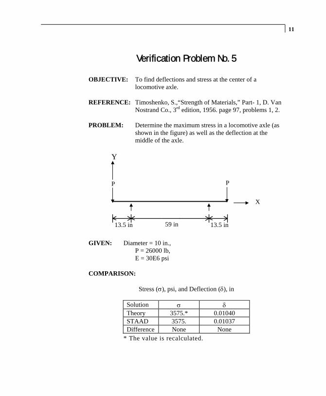
11
Verification Problem No. 5
OBJECTIVE: To find deflections and stress at the center of a locomotive axle.
REFERENCE: Timoshenko, S.,“Strength of Materials,” Part- 1, D. Van
Nostrand Co., 3rd edition, 1956. page 97, problems 1, 2. PROBLEM: Determine the maximum stress in a locomotive axle (as
shown in the figure) as well as the deflection at the middle of the axle.
59 in13.5 in 13.5 in
X
PP
Y
GIVEN: Diameter = 10 in., P = 26000 lb, E = 30E6 psi COMPARISON:
Stress (σ), psi, and Deflection (δ), in
Solution σ δ Theory 3575.* 0.01040 STAAD 3575. 0.01037 Difference None None
* The value is recalculated.
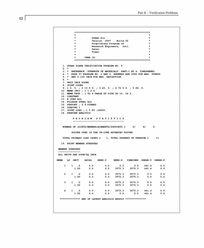
Part II – Verification Problems
12
**************************************************** * * * STAAD.Pro * * Version 2007 Build 02 * * Proprietary Program of * * Research Engineers, Intl. * * Date= * * Time= * * * * USER ID: * **************************************************** 1. STAAD PLANE VERIFICATION PROBLEM NO. 5 2. * 3. * REFERENCE 'STRENGTH OF MATERIALS' PART-1 BY S. TIMOSHENKO 4. * PAGE 97 PROBLEM NO. 1 AND 2. ANSWERS ARE 3580 FOR MAX. STRESS 5. * AND 0.104 INCH FOR MAX. DEFLECTION. 6. * 7. UNIT INCH POUND 8. JOINT COORD 9. 1 0. 0. ; 2 13.5 0. ; 3 43. 0. ; 4 72.5 0. ; 5 86. 0. 10. MEMB INCI ; 1 1 2 4 11. MEMB PROP ; 1 TO 4 TABLE ST PIPE OD 10. ID 0. 12. CONSTANT 13. E 30E6 ALL 14. POISSON STEEL ALL 15. SUPPORT ; 2 4 PINNED 16. LOADING 1 17. JOINT LOAD ; 1 5 FY -26000. 18. PERFORM ANALYSIS P R O B L E M S T A T I S T I C S ----------------------------------- NUMBER OF JOINTS/MEMBER+ELEMENTS/SUPPORTS = 5/ 4/ 2 SOLVER USED IS THE IN-CORE ADVANCED SOLVER TOTAL PRIMARY LOAD CASES = 1, TOTAL DEGREES OF FREEDOM = 11 19. PRINT MEMBER STRESSES MEMBER STRESSES --------------- ALL UNITS ARE POUN/SQ INCH MEMB LD SECT AXIAL BEND-Y BEND-Z COMBINED SHEAR-Y SHEAR-Z 1 1 .0 0.0 0.0 0.0 0.0 441.4 0.0 1.00 0.0 0.0 3575.3 3575.3 441.4 0.0 2 1 .0 0.0 0.0 3575.3 3575.3 0.0 0.0 1.00 0.0 0.0 3575.3 3575.3 0.0 0.0 3 1 .0 0.0 0.0 3575.3 3575.3 0.0 0.0 1.00 0.0 0.0 3575.3 3575.3 0.0 0.0 4 1 .0 0.0 0.0 3575.3 3575.3 441.4 0.0 1.00 0.0 0.0 0.0 0.0 441.4 0.0 ************** END OF LATEST ANALYSIS RESULT **************

13 20. PRINT DISPLACEMENTS JOINT DISPLACEMENT (INCH RADIANS) STRUCTURE TYPE = PLANE ------------------ JOINT LOAD X-TRANS Y-TRANS Z-TRANS X-ROTAN Y-ROTAN Z-ROTAN 1 1 0.00000 -0.01138 0.00000 0.00000 0.00000 0.00086 2 1 0.00000 0.00000 0.00000 0.00000 0.00000 0.00070 3 1 0.00000 0.01037 0.00000 0.00000 0.00000 0.00000 4 1 0.00000 0.00000 0.00000 0.00000 0.00000 -0.00070 5 1 0.00000 -0.01138 0.00000 0.00000 0.00000 -0.00086 ************** END OF LATEST ANALYSIS RESULT ************** 21. FINISH

Part II – Verification Problems
14
NOTES

15
Verification Problem No. 6
OBJECTIVE: To find the maximum moment due to a uniform load on the horizontal member in a 1x1 bay plane frame.
REFERENCE: McCormack, J. C., “Structural Analysis,” Intext
Educational Publishers, 3rd edition, 1975, page 383, example 22 - 5.
PROBLEM: Determine the maximum moment in the frame.
GIVEN: E and I same for all members. COMPARISON:
Moment, Kip-ft
Solution MMax
Theory 44.40 STAAD 44.44 Difference Small

Part II – Verification Problems
16
**************************************************** * * * STAAD.Pro * * Version 2007 Build 02 * * Proprietary Program of * * Research Engineers, Intl. * * Date= * * Time= * * * * USER ID: * **************************************************** 1. STAAD PLANE VERIFICATION PROBLEM NO. 6 2. * 3. * REFERENCE 'STRUCTURAL ANALYSIS' BY JACK C. MCCORMACK, 4. * PAGE 383 EXAMPLE 22-5, PLANE FRAME WITH NO SIDESWAY 5. * ANSWER - MAX BENDING = 44.4 FT-KIP 6. * 7. UNIT FT KIP 8. JOINT COORD 9. 1 0. 0. ; 2 0. 20. ; 3 20. 20. ; 4 20. 0. 10. MEMB INCI ; 1 1 2 3 11. MEMB PROP ; 1 2 3 PRIS AX 1. IZ 0.05 12. CONSTANT 13. E 4132E3 ALL 14. POISSON STEEL ALL 15. SUPPORT ; 1 4 FIXED 16. LOADING 1 ; MEMB LOAD ; 2 UNI Y -2.0 17. PERFORM ANAL P R O B L E M S T A T I S T I C S ----------------------------------- NUMBER OF JOINTS/MEMBER+ELEMENTS/SUPPORTS = 4/ 3/ 2 SOLVER USED IS THE IN-CORE ADVANCED SOLVER TOTAL PRIMARY LOAD CASES = 1, TOTAL DEGREES OF FREEDOM = 6 18. PRINT FORCES MEMBER END FORCES STRUCTURE TYPE = PLANE ----------------- ALL UNITS ARE -- KIP FEET (LOCAL ) MEMBER LOAD JT AXIAL SHEAR-Y SHEAR-Z TORSION MOM-Y MOM-Z 1 1 1 20.00 -3.33 0.00 0.00 0.00 -22.21 2 -20.00 3.33 0.00 0.00 0.00 -44.44 2 1 2 3.33 20.00 0.00 0.00 0.00 44.44 3 -3.33 20.00 0.00 0.00 0.00 -44.44 3 1 3 20.00 3.33 0.00 0.00 0.00 44.44 4 -20.00 -3.33 0.00 0.00 0.00 22.21 ************** END OF LATEST ANALYSIS RESULT ************** 19. FINISH

17
Verification Problem No. 7
OBJECTIVE: To find the joint deflection due to joint loads in a plane truss.
REFERENCE: McCormack, J. C., “Structural Analysis,” Intext
Educational Publishers, 3rd edition, 1975, page 271, example 18 - 2.
PROBLEM: Determine the vertical deflection at point 5 of the plane
truss structure shown in the figure.
GIVEN: AX 1-4 = 1 in2, AX 5-6 = 2 in2, AX 7-8 =1.5 in2, AX 9-11 = 3 in2, AX 12-13 = 4 in2, E = 30E3 ksi COMPARISON:
Deflection, in.
Solution δ5
Theory 2.63 STAAD 2.63 Difference None

Part II – Verification Problems
18
**************************************************** * * * STAAD.Pro * * Version 2007 Build 02 * * Proprietary Program of * * Research Engineers, Intl. * * Date= * * Time= * * * * USER ID: * **************************************************** 1. STAAD TRUSS VERIFICATION PROBLEM NO. 7 2. * 3. * REFERENCE 'STRUCTURAL ANALYSIS' BY JACK MCCORMACK, PAGE 4. * 271 EXAMPLE 18-2. ANSWER - Y-DISP AT JOINT 5 = 2.63 INCH 5. * 6. UNIT FT KIP 7. JOINT COORD 8. 1 0 0 0 5 60 0 0 9. 6 15. 7.5 ; 7 30. 15. ; 8 45. 7.5 10. MEMB INCI 11. 1 2 6 ; 2 3 4 ; 3 4 8 ; 4 4 5 ; 5 1 2 12. 6 2 3 ; 7 3 6 ; 8 3 8 ; 9 3 7 13. 10 1 6 ; 11 5 8 ; 12 6 7 13 14. UNIT INCH 15. MEMB PROP 16. 1 TO 4 PRI AX 1.0 17. 5 6 PRIS AX 2. 18. 7 8 PRI AX 1.5 19. 9 10 11 PRI AX 3. 20. 12 13 PRI AX 4. 21. CONSTANT 22. E 30E3 ALL 23. POISSON STEEL ALL 24. SUPPORT 25. 1 PINNED ; 3 FIXED BUT FX MZ 26. LOAD 1 VERTICAL LOAD 27. JOINT LOAD 28. 2 4 5 FY -20.0 29. PERFORM ANALYSIS P R O B L E M S T A T I S T I C S ----------------------------------- NUMBER OF JOINTS/MEMBER+ELEMENTS/SUPPORTS = 8/ 13/ 2 SOLVER USED IS THE IN-CORE ADVANCED SOLVER TOTAL PRIMARY LOAD CASES = 1, TOTAL DEGREES OF FREEDOM = 13 30. PRINT DISPLACEMENTS JOINT DISPLACEMENT (INCH RADIANS) STRUCTURE TYPE = TRUSS ------------------ JOINT LOAD X-TRANS Y-TRANS Z-TRANS X-ROTAN Y-ROTAN Z-ROTAN 1 1 0.00000 0.00000 0.00000 0.00000 0.00000 0.00000 2 1 -0.12000 0.18000 0.00000 0.00000 0.00000 0.00000 3 1 -0.24000 0.00000 0.00000 0.00000 0.00000 0.00000 4 1 -0.48000 -0.89516 0.00000 0.00000 0.00000 0.00000 5 1 -0.72000 -2.63033 0.00000 0.00000 0.00000 0.00000 6 1 -0.00820 0.24000 0.00000 0.00000 0.00000 0.00000 7 1 0.29758 -0.12000 0.00000 0.00000 0.00000 0.00000 8 1 0.06578 -0.83516 0.00000 0.00000 0.00000 0.00000 ************** END OF LATEST ANALYSIS RESULT ************** 31. FINISH

19
Verification Problem No. 8
OBJECTIVE: To find the maximum moment due to a concentrated load on the horizontal member in a 1x1 bay plane frame.
REFERENCE: McCormack, J. C., “Structural Analysis,” Intext
Educational Publishers, 3rd edition, 1975, page 385, problem 22 - 6.
PROBLEM: Determine the maximum moment in the structure.
GIVEN: E and I same for all members COMPARISON:
Moment, Kip-ft
Solution MMax
Theory 69.40 STAAD 69.44 Difference Small

Part II – Verification Problems
20
**************************************************** * * * STAAD.Pro * * Version 2007 Build 02 * * Proprietary Program of * * Research Engineers, Intl. * * Date= * * Time= * * * * USER ID: * **************************************************** 1. STAAD PLANE VERIFICATION PROBLEM NO. 8 2. * 3. * PLANE FRAME WITH SIDESWAY. REFERENCE 'STRUCTURAL ANALYSIS' 4. * BY JACK MCCORMACK. PAGE 385 PROB 22-6. 5. * ANSWER - MAX BENDING IN MEMB 1 = 69.4 KIP-FT 6. * 7. UNIT FT KIP 8. JOINT COORD 9. 1 0. 10. ; 2 0 30 ; 3 30 30 ; 4 30 0 10. MEMB INCI 11. 1 1 2 3 12. MEMB PROP AMERICAN 13. 1 2 3 TAB ST W12X26 14. CONSTANT 15. E 4176E3 16. POISSON STEEL ALL 17. SUPPORT ; 1 4 FIXED 18. LOAD 1 VERTICAL LOAD 19. MEMBER LOAD 20. 2 CON Y -30. 10. 21. PERFORM ANALYSIS P R O B L E M S T A T I S T I C S ----------------------------------- NUMBER OF JOINTS/MEMBER+ELEMENTS/SUPPORTS = 4/ 3/ 2 SOLVER USED IS THE IN-CORE ADVANCED SOLVER TOTAL PRIMARY LOAD CASES = 1, TOTAL DEGREES OF FREEDOM = 6 22. PRINT FORCES MEMBER END FORCES STRUCTURE TYPE = PLANE ----------------- ALL UNITS ARE -- KIP FEET (LOCAL ) MEMBER LOAD JT AXIAL SHEAR-Y SHEAR-Z TORSION MOM-Y MOM-Z 1 1 1 20.09 -3.74 0.00 0.00 0.00 -5.34 2 -20.09 3.74 0.00 0.00 0.00 -69.44 2 1 2 3.74 20.09 0.00 0.00 0.00 69.44 3 -3.74 9.91 0.00 0.00 0.00 -66.66 3 1 3 9.91 3.74 0.00 0.00 0.00 66.66 4 -9.91 -3.74 0.00 0.00 0.00 45.51 ************** END OF LATEST ANALYSIS RESULT ************** 23. FINISH

21
Verification Problem No. 9
OBJECTIVE: To find the maximum moment due to lateral joint loads in a 1x2 bay plane frame.
REFERENCE: McCormack, J. C., “Structural Analysis,” Intext
Educational Publishers, 3rd edition, 1975, page 388, example 22 - 7.
PROBLEM: Determine the maximum moment in the frame.
GIVEN: E and I same for all members. COMPARISON:
Moment, Kip-ft
Solution MMax
Theory 176.40 STAAD 178.01 Difference 0.91%

Part II – Verification Problems
22
**************************************************** * * * STAAD.Pro * * Version 2007 Build 02 * * Proprietary Program of * * Research Engineers, Intl. * * Date= * * Time= * * * * USER ID: * **************************************************** 1. STAAD PLANE VERIFICATION PROB NO. 9 2. * 3. * MULTIPLE LEVEL PLANE FRAME WITH HORIZONTAL LOAD. 4. * REFERENCE 'STRUCTURAL ANALYSIS' BY JACK MCCORMACK, 5. * PAGE 388, PROB 22-7. ANSWER - MAX MOM IN MEMB 1 = 176.4 K-F 6. * 7. UNIT FT KIP 8. JOINT COORD 9. 1 0 0 0 5 0 40 0 2 ; 2 20 0 0 6 20 40 0 2 10. MEMB INCI 11. 1 1 3 2 ; 3 3 5 4 ; 5 3 4 ; 6 5 6 12. MEMB PROP 13. 1 TO 6 PRI AX .2 IZ .1 14. CONSTANT 15. E 4176E3 16. POISSON STEEL ALL 17. SUPPORT ; 1 2 FIXED 18. LOAD 1 HORIZONTAL LOAD 19. JOINT LOAD 20. 3 FX 20 ; 5 FX 10 21. PERFORM ANALYS P R O B L E M S T A T I S T I C S ----------------------------------- NUMBER OF JOINTS/MEMBER+ELEMENTS/SUPPORTS = 6/ 6/ 2 SOLVER USED IS THE IN-CORE ADVANCED SOLVER TOTAL PRIMARY LOAD CASES = 1, TOTAL DEGREES OF FREEDOM = 12 22. PRINT FORCES MEMBER END FORCES STRUCTURE TYPE = PLANE ----------------- ALL UNITS ARE -- KIP FEET (LOCAL ) MEMBER LOAD JT AXIAL SHEAR-Y SHEAR-Z TORSION MOM-Y MOM-Z 1 1 1 -22.26 15.06 0.00 0.00 0.00 178.01 3 22.26 -15.06 0.00 0.00 0.00 123.16 2 1 2 22.26 14.94 0.00 0.00 0.00 176.73 4 -22.26 -14.94 0.00 0.00 0.00 122.10 3 1 3 -6.51 4.97 0.00 0.00 0.00 34.49 5 6.51 -4.97 0.00 0.00 0.00 64.93 4 1 4 6.51 5.03 0.00 0.00 0.00 35.34 6 -6.51 -5.03 0.00 0.00 0.00 65.24 5 1 3 9.91 -15.75 0.00 0.00 0.00 -157.65 4 -9.91 15.75 0.00 0.00 0.00 -157.44 6 1 5 5.03 -6.51 0.00 0.00 0.00 -64.93 6 -5.03 6.51 0.00 0.00 0.00 -65.24 ************** END OF LATEST ANALYSIS RESULT ************** 23. FINISH

23
Verification Problem No. 10
OBJECTIVE: To find the maximum axial force and moment due to load and moment applied at a joint in a space frame.
REFERENCE: Weaver Jr., W., “Computer Programs for Structural
Analysis,” page 146, problem 8.
PROBLEM: Determine the maximum axial force and moment in the space structure.
GIVEN: E = 30E3 ksi, AX = 11 in2
IX = 83 in4 IY = 56 in4
IZ = 56 in4
COMPARISON:
Solution FMax (kips) MY,Max (kip-in) MZ,Max (kip-in) Reference 1.47 84.04 95.319 STAAD 1.47 84.04 96.120 Difference None None Small

Part II – Verification Problems
24 **************************************************** * * * STAAD.Pro * * Version 2007 Build 02 * * Proprietary Program of * * Research Engineers, Intl. * * Date= * * Time= * * * * USER ID: * **************************************************** 1. STAAD SPACE VERIFICATION PROB NO. 10 2. * 3. * REFERENCE 'COMPUTER PROGRAMS FOR STRUCTURAL ANALYSIS' 4. * BY WILLIAM WEAVER JR. PAGE 146 STRUCTURE NO. 8. 5. * ANSWER - MAX AXIAL FORCE= 1.47 (MEMB 3) 6. * MAX BEND-Y= 84.04, MAX BEND-Z= 95.319 (BOTH MEMB 3) 7. * 8. UNIT INCH KIP 9. JOINT COORD 10. 1 0 120 0 ; 2 240 120 0 11. 3 0 0 0 ; 4 360 0 120 12. MEMB INCI 13. 1 1 2 ; 2 3 1 ; 3 2 4 14. MEMB PROP 15. 1 2 3 PRIS AX 11. IX 83. IY 56. IZ 56 16. CONSTANT ; E 30000. ALL 17. POISS .25 ALL 18. SUPPORT 19. 3 4 FIXED 20. LOAD 1 JOINT LOAD 21. JOINT LOAD 22. 1 FX 2. ; 2 FY -1. ; 2 MZ -120. 23. PERFORM ANAL P R O B L E M S T A T I S T I C S ----------------------------------- NUMBER OF JOINTS/MEMBER+ELEMENTS/SUPPORTS = 4/ 3/ 2 SOLVER USED IS THE IN-CORE ADVANCED SOLVER TOTAL PRIMARY LOAD CASES = 1, TOTAL DEGREES OF FREEDOM = 12 24. PRINT ANALYSIS RESULT JOINT DISPLACEMENT (INCH RADIANS) STRUCTURE TYPE = SPACE ------------------ JOINT LOAD X-TRANS Y-TRANS Z-TRANS X-ROTAN Y-ROTAN Z-ROTAN 1 1 0.22267 0.00016 -0.17182 -0.00255 0.00217 -0.00213 2 1 0.22202 -0.48119 -0.70161 -0.00802 0.00101 -0.00435 3 1 0.00000 0.00000 0.00000 0.00000 0.00000 0.00000 4 1 0.00000 0.00000 0.00000 0.00000 0.00000 0.00000 SUPPORT REACTIONS -UNIT KIP INCH STRUCTURE TYPE = SPACE ----------------- JOINT LOAD FORCE-X FORCE-Y FORCE-Z MOM-X MOM-Y MOM Z 3 1 -1.10 -0.43 0.22 48.78 -17.97 96.12 4 1 -0.90 1.43 -0.22 123.08 47.25 -11.72
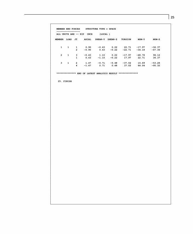
25 MEMBER END FORCES STRUCTURE TYPE = SPACE ----------------- ALL UNITS ARE -- KIP INCH (LOCAL ) MEMBER LOAD JT AXIAL SHEAR-Y SHEAR-Z TORSION MOM-Y MOM-Z 1 1 1 0.90 -0.43 0.22 22.71 -17.97 -36.37 2 -0.90 0.43 -0.22 -22.71 -34.18 -67.36 2 1 3 -0.43 1.10 0.22 -17.97 -48.78 96.12 1 0.43 -1.10 -0.22 17.97 22.71 36.37 3 1 2 1.47 -0.71 -0.48 -37.02 15.69 -53.28 4 -1.47 0.71 0.48 37.02 84.04 -95.32 ************** END OF LATEST ANALYSIS RESULT ************** 25. FINISH

Part II – Verification Problems
26
NOTES
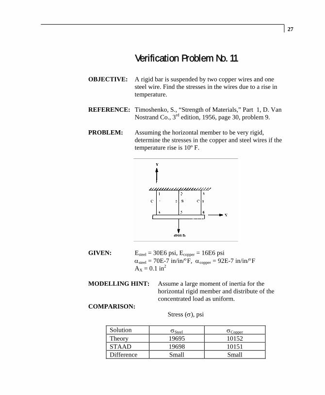
27
Verification Problem No. 11
OBJECTIVE: A rigid bar is suspended by two copper wires and one steel wire. Find the stresses in the wires due to a rise in temperature.
REFERENCE: Timoshenko, S., “Strength of Materials,” Part 1, D. Van
Nostrand Co., 3rd edition, 1956, page 30, problem 9. PROBLEM: Assuming the horizontal member to be very rigid,
determine the stresses in the copper and steel wires if the temperature rise is 10º F.
GIVEN: Esteel = 30E6 psi, Ecopper = 16E6 psi αsteel = 70E-7 in/in/°F, αcopper = 92E-7 in/in/°F AX = 0.1 in2
MODELLING HINT: Assume a large moment of inertia for the
horizontal rigid member and distribute of the concentrated load as uniform.
COMPARISON: Stress (σ), psi
Solution σSteel σCopper
Theory 19695 10152 STAAD 19698 10151 Difference Small Small

Part II – Verification Problems
28
**************************************************** * * * STAAD.Pro * * Version 2007 Build 02 * * Proprietary Program of * * Research Engineers, Intl. * * Date= * * Time= * * * * USER ID: * **************************************************** 1. STAAD PLANE VERIFICATION PROB NO 11 2. * 3. * THIS EXAMPLE IS TAKEN FROM 'STRENGTH OF MATERIALS' BY 4. * TIMOSHENKO (PART 1), PAGE 30, PROB 9. 5. * THE ANSWERS ARE 19700 PSI AND 10200 PSI. 6. * 7. UNIT INCH POUND 8. JOINT COORD 9. 1 0. 20. ; 2 5. 20. ; 3 10. 20. 10. 4 0. 0. ; 5 5. 0. ; 6 10. 0. 11. MEMB INCI 12. 1 1 4 3 ; 4 4 5 5 13. MEMB PROP 14. 1 2 3 PRI AX 0.1 ; 4 5 PRI AX 1. IZ 100. 15. CONSTANT ; E 30E6 MEMB 2 4 5 16. E 16E6 MEMB 1 3 17. POISSON 0.15 ALL 18. ALPHA 92E-7 MEMB 1 3 ; ALPHA 70E-7 MEMB 2 19. MEMB TRUSS ; 1 2 3 20. SUPPORT ; 1 2 3 PINNED 21. LOADING 1 VERT LOAD + TEMP LOAD 22. MEMB LOAD ;4 5 UNI Y -400. 23. TEMP LOAD ; 1 2 3 TEMP 10. 24. PERFORM ANALYSIS P R O B L E M S T A T I S T I C S ----------------------------------- NUMBER OF JOINTS/MEMBER+ELEMENTS/SUPPORTS = 6/ 5/ 3 SOLVER USED IS THE IN-CORE ADVANCED SOLVER TOTAL PRIMARY LOAD CASES = 1, TOTAL DEGREES OF FREEDOM = 12 ZERO STIFFNESS IN DIRECTION 6 AT JOINT 1 EQN.NO. 1 LOADS APPLIED OR DISTRIBUTED HERE FROM ELEMENTS WILL BE IGNORED. THIS MAY BE DUE TO ALL MEMBERS AT THIS JOINT BEING RELEASED OR EFFECTIVELY RELEASED IN THIS DIRECTION. ZERO STIFFNESS IN DIRECTION 6 AT JOINT 2 EQN.NO. 2 ZERO STIFFNESS IN DIRECTION 6 AT JOINT 3 EQN.NO. 3 ***WARNING - INSTABILITY AT JOINT 5 DIRECTION = FX PROBABLE CAUSE SINGULAR-ADDING WEAK SPRING K-MATRIX DIAG= 1.2000001E+04 L-MATRIX DIAG= 0.0000000E+00 EQN NO 7 ***NOTE - VERY WEAK SPRING ADDED FOR STABILITY 25. PRINT STRESSES

29 MEMBER STRESSES --------------- ALL UNITS ARE POUN/SQ INCH MEMB LD SECT AXIAL BEND-Y BEND-Z COMBINED SHEAR-Y SHEAR-Z 1 1 .0 10150.8 T 0.0 0.0 10150.8 0.0 0.0 1.00 10150.8 T 0.0 0.0 10150.8 0.0 0.0 2 1 .0 19698.3 T 0.0 0.0 19698.3 0.0 0.0 1.00 19698.3 T 0.0 0.0 19698.3 0.0 0.0 3 1 .0 10150.8 T 0.0 0.0 10150.8 0.0 0.0 1.00 10150.8 T 0.0 0.0 10150.8 0.0 0.0 4 1 .0 0.0 0.0 0.0 0.0 1522.6 0.0 1.00 0.0 0.0 3.8 3.8 1477.4 0.0 5 1 .0 0.0 0.0 3.8 3.8 1477.4 0.0 1.00 0.0 0.0 0.0 0.0 1522.6 0.0 ************** END OF LATEST ANALYSIS RESULT ************** 26. FINISH

Part II – Verification Problems
30
NOTES

31
Verification Problem No. 12
OBJECTIVE: To find the joint deflection and member stress due to a joint load in a plane truss.
REFERENCE: Timoshenko, S., “Strength of Materials,” Part 1, D. Van
Nostrand Co., Inc., 3rd edition, 1956, page 10, problem 2. PROBLEM: Determine the vertical deflection at point A and the
member stresses.
L=180”A=0.5 in 2
L=180”A=0.5 in 2
P=5000 lb
30° 30 °
GIVEN: AX = 0.5 in2, E = 30E6 psi COMPARISON:
Stress (σ), psi and Deflection (δ), in.
Solution σA δA
Theory 10000. 0.12 STAAD 10000. 0.12 Difference None None
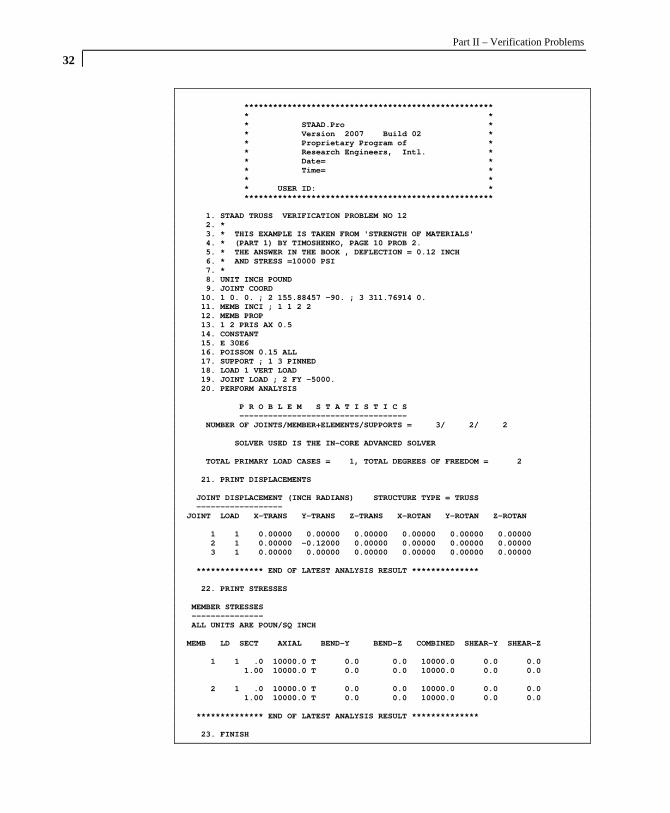
Part II – Verification Problems
32
**************************************************** * * * STAAD.Pro * * Version 2007 Build 02 * * Proprietary Program of * * Research Engineers, Intl. * * Date= * * Time= * * * * USER ID: * **************************************************** 1. STAAD TRUSS VERIFICATION PROBLEM NO 12 2. * 3. * THIS EXAMPLE IS TAKEN FROM 'STRENGTH OF MATERIALS' 4. * (PART 1) BY TIMOSHENKO, PAGE 10 PROB 2. 5. * THE ANSWER IN THE BOOK , DEFLECTION = 0.12 INCH 6. * AND STRESS =10000 PSI 7. * 8. UNIT INCH POUND 9. JOINT COORD 10. 1 0. 0. ; 2 155.88457 -90. ; 3 311.76914 0. 11. MEMB INCI ; 1 1 2 2 12. MEMB PROP 13. 1 2 PRIS AX 0.5 14. CONSTANT 15. E 30E6 16. POISSON 0.15 ALL 17. SUPPORT ; 1 3 PINNED 18. LOAD 1 VERT LOAD 19. JOINT LOAD ; 2 FY -5000. 20. PERFORM ANALYSIS P R O B L E M S T A T I S T I C S ----------------------------------- NUMBER OF JOINTS/MEMBER+ELEMENTS/SUPPORTS = 3/ 2/ 2 SOLVER USED IS THE IN-CORE ADVANCED SOLVER TOTAL PRIMARY LOAD CASES = 1, TOTAL DEGREES OF FREEDOM = 2 21. PRINT DISPLACEMENTS JOINT DISPLACEMENT (INCH RADIANS) STRUCTURE TYPE = TRUSS ------------------ JOINT LOAD X-TRANS Y-TRANS Z-TRANS X-ROTAN Y-ROTAN Z-ROTAN 1 1 0.00000 0.00000 0.00000 0.00000 0.00000 0.00000 2 1 0.00000 -0.12000 0.00000 0.00000 0.00000 0.00000 3 1 0.00000 0.00000 0.00000 0.00000 0.00000 0.00000 ************** END OF LATEST ANALYSIS RESULT ************** 22. PRINT STRESSES MEMBER STRESSES --------------- ALL UNITS ARE POUN/SQ INCH MEMB LD SECT AXIAL BEND-Y BEND-Z COMBINED SHEAR-Y SHEAR-Z 1 1 .0 10000.0 T 0.0 0.0 10000.0 0.0 0.0 1.00 10000.0 T 0.0 0.0 10000.0 0.0 0.0 2 1 .0 10000.0 T 0.0 0.0 10000.0 0.0 0.0 1.00 10000.0 T 0.0 0.0 10000.0 0.0 0.0 ************** END OF LATEST ANALYSIS RESULT ************** 23. FINISH

33

Part II – Verification Problems
34