staad tutorial 3 steel floor
DESCRIPTION
STAAD Tutorial 3 Steel FloorTRANSCRIPT

ENG 7704ENG 7704
Design of Steel StructuresDesign of Steel Structures
Analysis & Design of a Steel Floor using STAAD
Tamer SabrahPh.D Candidate of Civil Engineering
11
Session 3: July 10, 2006Session 3: July 10, 2006

22
SteelSteel Floor PlanFloor Plan
Main vertical Loadsare:
Own weight
Flooring = 1.5 kn/m2
Live Loads = 2.0 kn/m2

Main Steps of ModelingEntering job information.Building model geometry.Defining member properties, sections.Assigning loads (load cases, combinations..)Defining pre-analysis print out, analysis type, and post-analysis printout.Defining design requirements.
33

Select from here the units,
that we will deal with.
Assume that the units are:
meter, & kilo Newton.
For a new file, select the
type of structure you want
to solve.
Select Floor type
44
OPEN A NEW FILE: FLOOR TYPEOPEN A NEW FILE: FLOOR TYPE

55
GO TO EDIT JOB INFORMATIONGO TO EDIT JOB INFORMATION

1. ENTERING JOB INFORMATION.
66
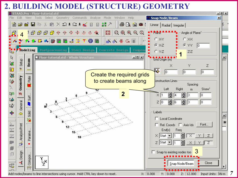
2. BUILDING MODEL (STRUCTURE) GEOMETRY
Create the required grids to create beams along
11
22
3
4
77

88
Create The Beams Over The Grid Construction Lines In The XCreate The Beams Over The Grid Construction Lines In The X--ZPlaneZPlane
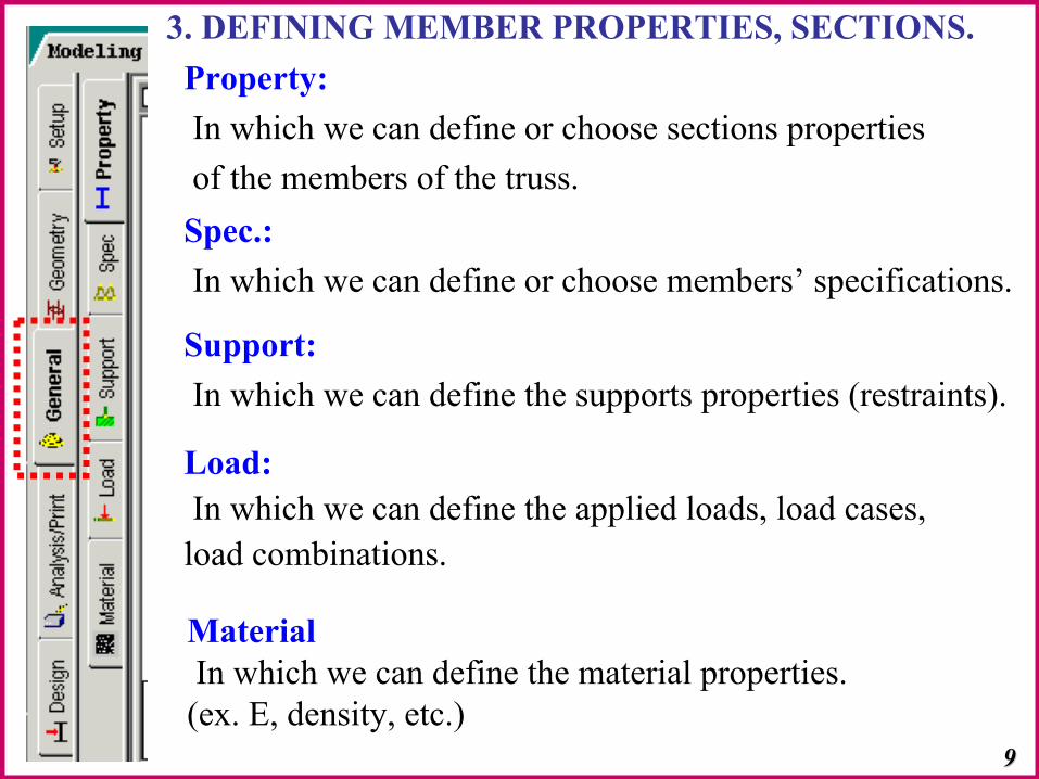
Property:In which we can define or choose sections propertiesof the members of the truss.Spec.:In which we can define or choose members’ specifications.
Support:In which we can define the supports properties (restraints).
Load:In which we can define the applied loads, load cases, load combinations.
MaterialIn which we can define the material properties. (ex. E, density, etc.)
3. DEFINING MEMBER PROPERTIES, SECTIONS.
99

1010
Assume your beams crossAssume your beams cross--sections following the Canadian Tablessections following the Canadian Tables
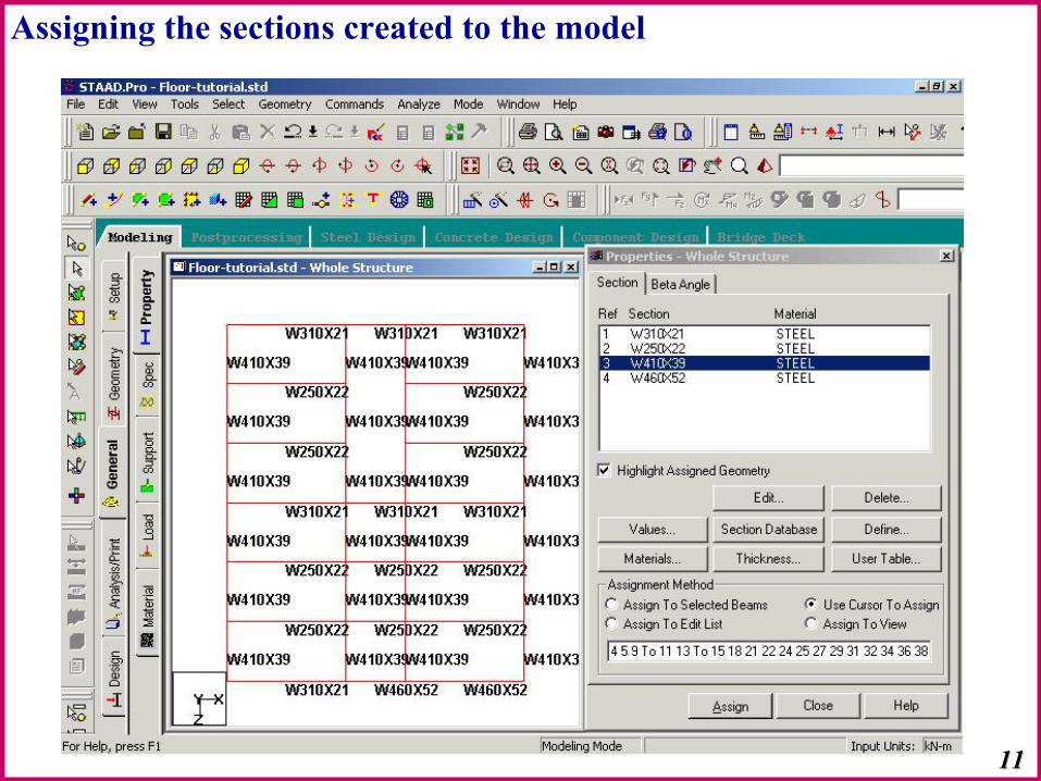
Assigning the sections created to the model
1111
1212
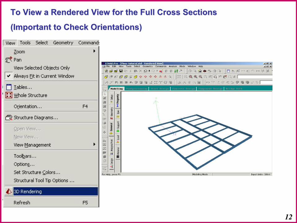
To View a Rendered View for the Full Cross Sections To View a Rendered View for the Full Cross Sections
(Important to Check Orientations)(Important to Check Orientations)
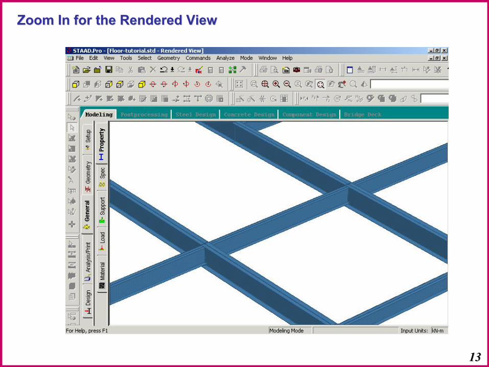
1313
Zoom In for the Rendered ViewZoom In for the Rendered View

Define Supports Locations
1414

1515
Sec. Beams are simple beams, so Create A Moment Release Sec. Beams are simple beams, so Create A Moment Release around the Zaround the Z--Axis for the Secondary Beams at the intersections Axis for the Secondary Beams at the intersections with the Main Girders.with the Main Girders.

4. DEFINING LOADS
1616
Create your Different Primary load CasesCreate your Different Primary load Cases

1717
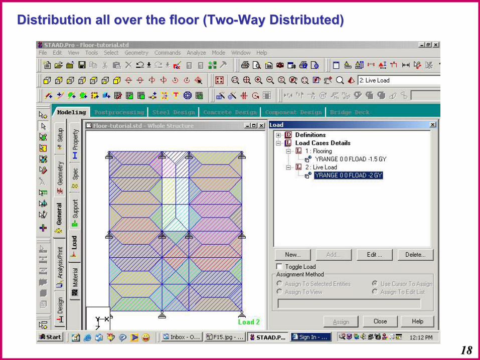
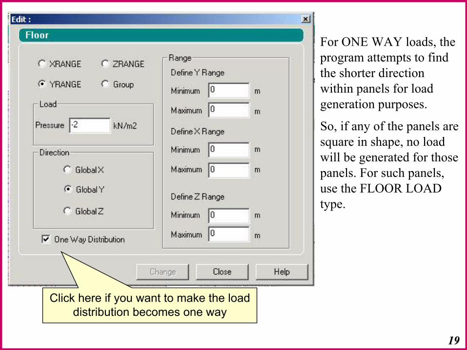
Define Load as Floor Load TypeDefine Load as Floor Load Type
1818
Distribution all over the floor (TwoDistribution all over the floor (Two--Way Distributed)Way Distributed)
1919
Click here if you want to make the load distribution becomes one way
For ONE WAY loads, the program attempts to find the shorter direction within panels for load generation purposes.
So, if any of the panels are square in shape, no load will be generated for those panels. For such panels, use the FLOOR LOAD type.

2020
One Way Distribution: One Way Distribution:
Take care: It will not put load for twoTake care: It will not put load for two-- way slabsway slabs
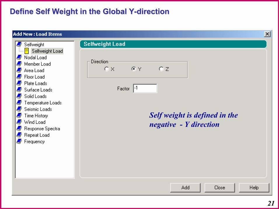
Self weight is defined in the negative - Y direction
2121
Define Self Weight in the Global YDefine Self Weight in the Global Y--directiondirection
2222
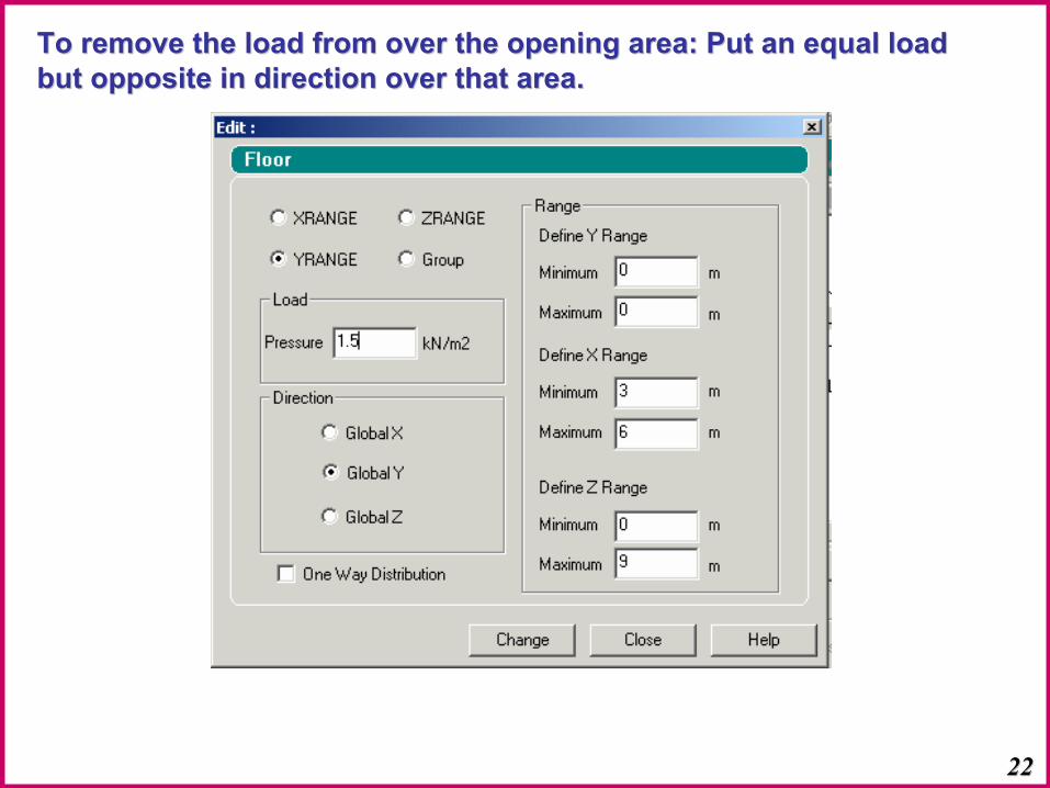
To remove the load from over the opening area: Put an equal loadTo remove the load from over the opening area: Put an equal loadbut opposite in direction over that area.but opposite in direction over that area.

2323
Create Load CombinationCreate Load Combination
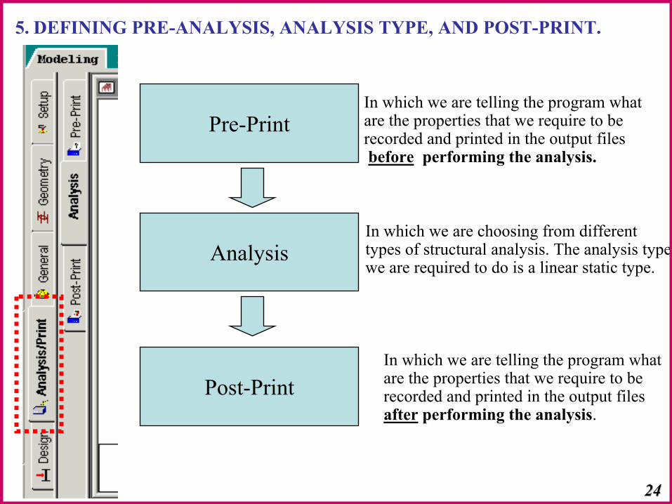
Pre-Print
Analysis
Post-Print
In which we are choosing from different types of structural analysis. The analysis typewe are required to do is a linear static type.
In which we are telling the program what are the properties that we require to be recorded and printed in the output filesbefore performing the analysis.
In which we are telling the program what are the properties that we require to be recorded and printed in the output files after performing the analysis.
5. DEFINING PRE-ANALYSIS, ANALYSIS TYPE, AND POST-PRINT.
2424
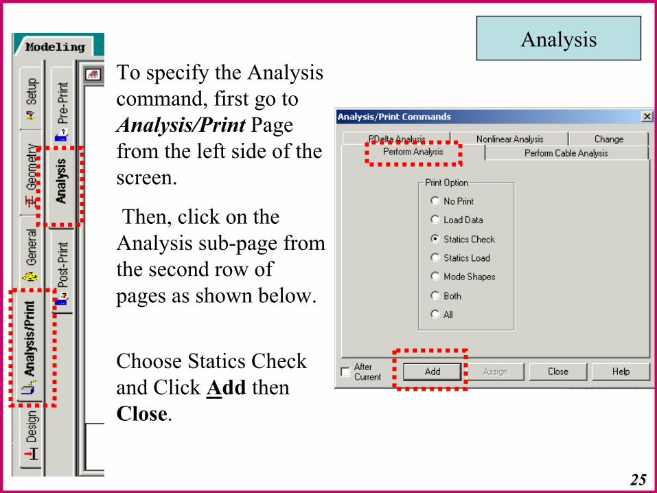
To specify the Analysis command, first go to Analysis/Print Page from the left side of the screen.
Then, click on the Analysis sub-page from the second row of pages as shown below.
Choose Statics Check and Click Add then Close.
Analysis
2525
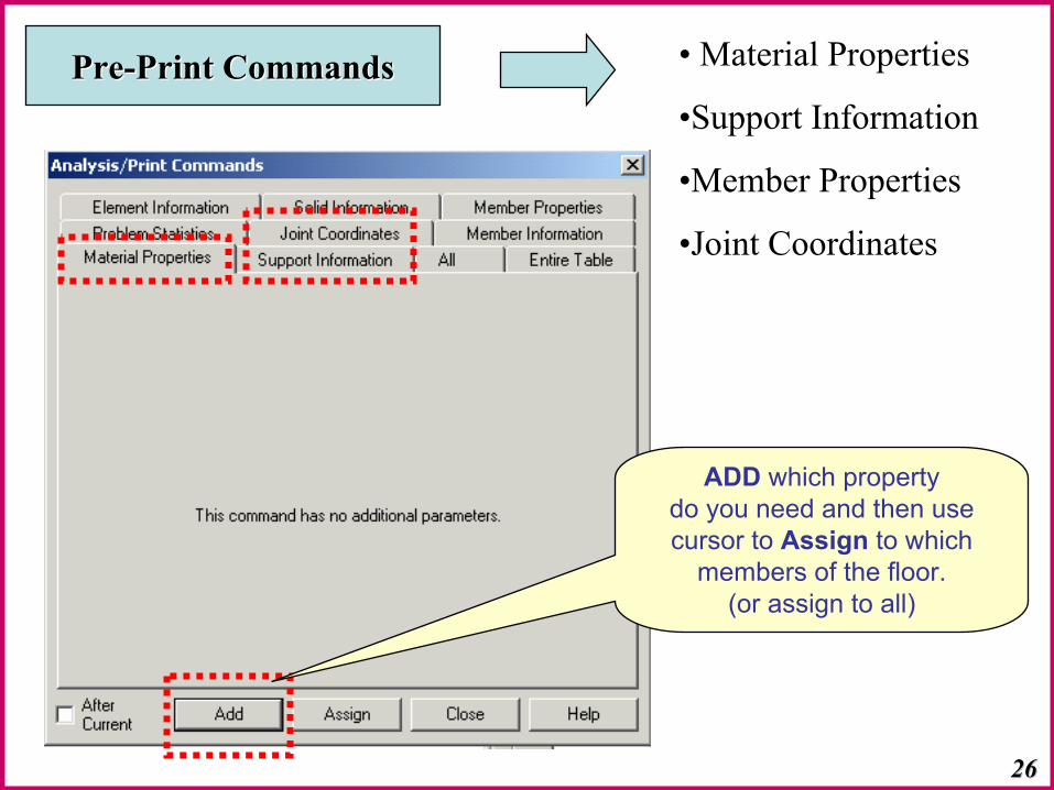
PrePre--Print CommandsPrint Commands • Material Properties
•Support Information
•Member Properties
•Joint Coordinates
2626
ADD which property do you need and then usecursor to Assign to which
members of the floor.(or assign to all)
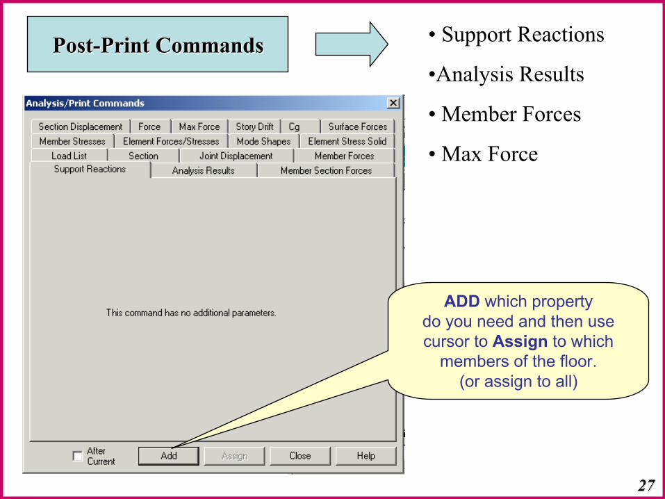
• Support Reactions
•Analysis Results
• Member Forces
• Max Force
PostPost--Print CommandsPrint Commands
2727
ADD which property do you need and then usecursor to Assign to which
members of the floor.(or assign to all)

6. DEFINING DESIGN REQUIREMENTS.
To specify steel design parameters, go to Design | Steel Page from the left side of the screen. Make sure that under the Current Codeselections on the top right hand side, Canadian is selected.
2828
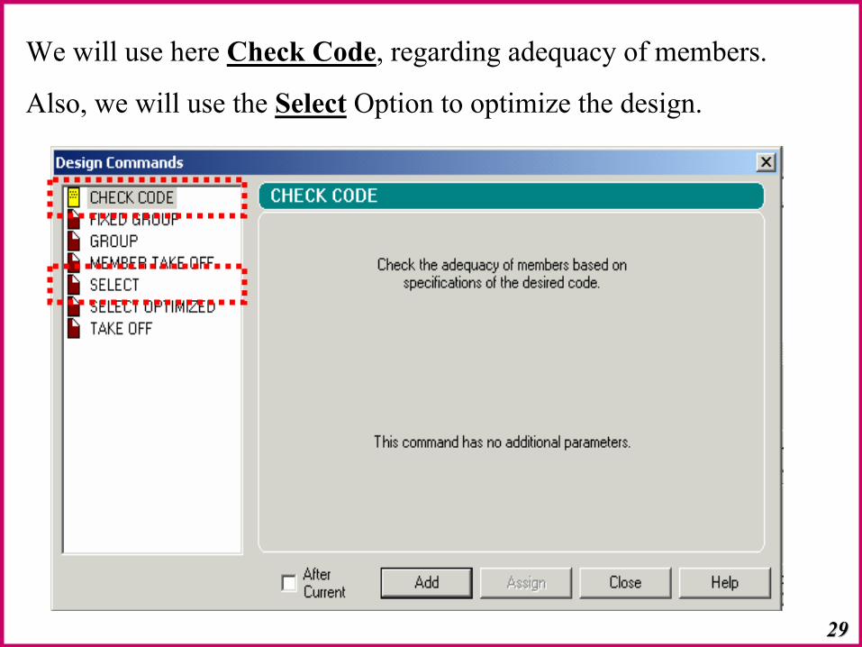
We will use here Check Code, regarding adequacy of members.
Also, we will use the Select Option to optimize the design.
2929

3030
Now, the model is ready to run analysisNow, the model is ready to run analysis
Remember: if you use the select option, your results will be showed for the selected members made by Staad.
Visualization of Results
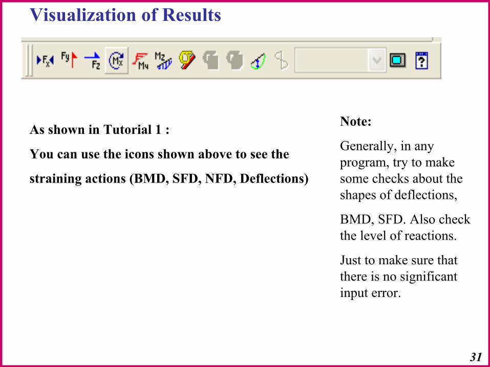
Note:
Generally, in any program, try to make some checks about the shapes of deflections,
BMD, SFD. Also check the level of reactions.
Just to make sure that there is no significant input error.
As shown in Tutorial 1 :
You can use the icons shown above to see the
straining actions (BMD, SFD, NFD, Deflections)
3131
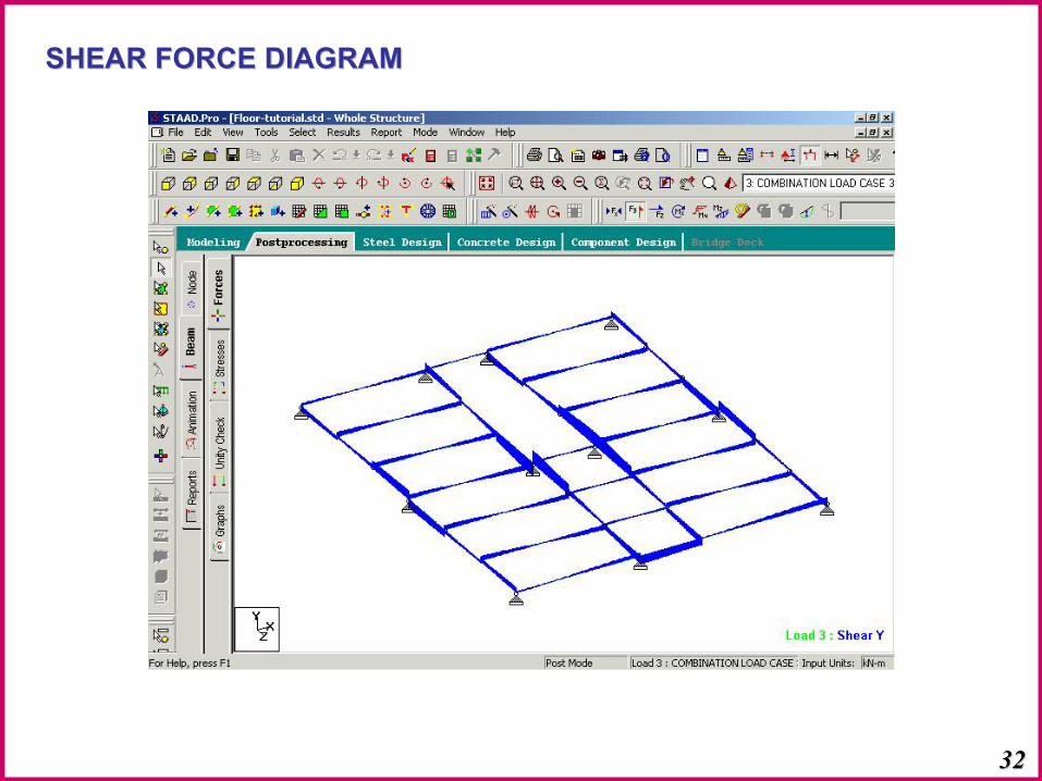
SHEAR FORCE DIAGRAMSHEAR FORCE DIAGRAM
3232

BENDING MOMENT DIAGRAMBENDING MOMENT DIAGRAM
3333
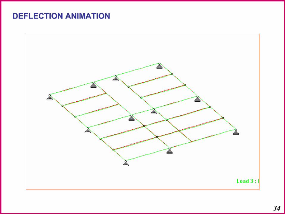
DEFLECTION ANIMATIONDEFLECTION ANIMATION
3434
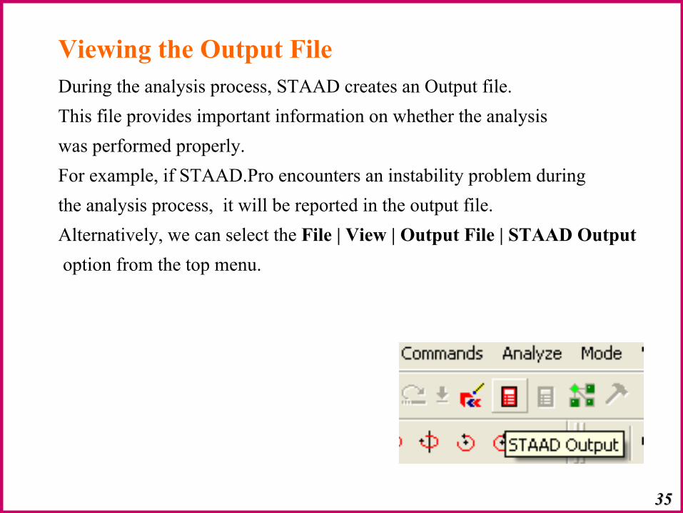
Viewing the Output FileDuring the analysis process, STAAD creates an Output file. This file provides important information on whether the analysiswas performed properly. For example, if STAAD.Pro encounters an instability problem during the analysis process, it will be reported in the output file. Alternatively, we can select the File | View | Output File | STAAD Outputoption from the top menu.
3535
3636
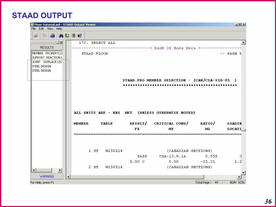
STAAD OUTPUTSTAAD OUTPUT
3737
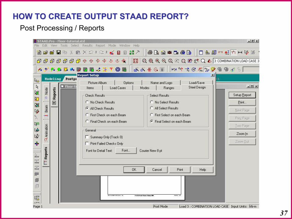
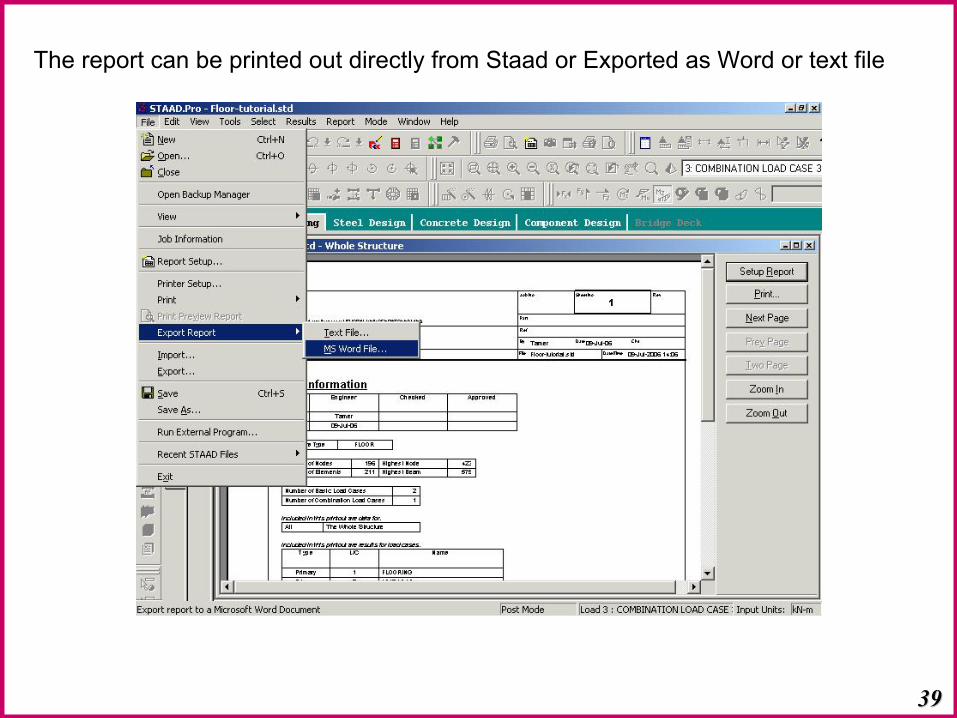
HOW TO CREATE OUTPUT STAAD REPORT?HOW TO CREATE OUTPUT STAAD REPORT?Post Processing / Reports
3838
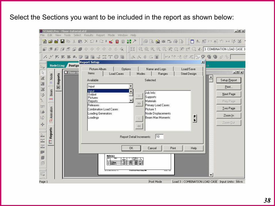
Select the Sections you want to be included in the report as shown below:
3939
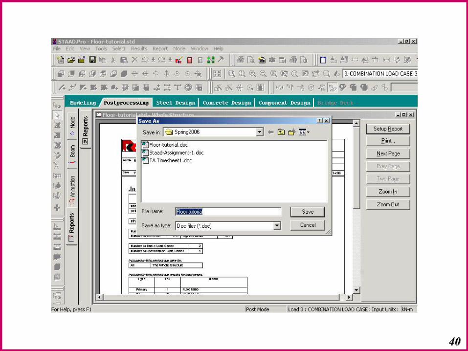
The report can be printed out directly from Staad or Exported as Word or text file
4040

Questions ?Questions ?
ThanksThanks
This tutorial can be downloaded from the following link :www.engr.mun.ca/~sabrah/Staad-Tut3.pdf
41414141© Tamer Sabrah - 2006