staad(x) tower usermanual en
TRANSCRIPT

STAAD(X) Tower®
V8i (SELECTseries 3)
User Manual
Last Updated: 30 June 2011
DAA039320-1/0003

Copyright Information
Trademark NoticeBentley, the "B" Bentley logo, STAAD(X) are registered or nonregistered trademarks of Bentley Systems,Inc. or Bentley Software, Inc. All other marks are the property of their respective owners.
Copyright Notice© 2011, Bentley Systems, Incorporated. All Rights Reserved.
Including software, file formats, and audiovisual displays; may only be used pursuant to applicablesoftware license agreement; contains confidential and proprietary information of Bentley Systems,Incorporated and/or third parties which is protected by copyright and trade secret law and may not beprovided or otherwise made available without proper authorization.
AcknowledgmentsWindows, Vista, SQL Server, MSDE, .NET, DirectX are registered trademarks of Microsoft Corporation.
Intel is a registered trademark of Intel Corporation.
AutoCAD is a registered trademark of Autodesk, Inc.
Adobe, the Adobe logo, Acrobat, the Acrobat logo are registered trademarks of Adobe SystemsIncorporated.
Portions Copyright © Developer Express Inc.
Portions Copyright © Visual Kinematic, Inc.
Portions Copyright © MadCap Software, Inc.
User Manual — i

Restricted Rights LegendsIf this software is acquired for or on behalf of the United States of America, its agencies and/orinstrumentalities ("U.S. Government"), it is provided with restricted rights. This software andaccompanying documentation are "commercial computer software" and "commercial computer softwaredocumentation," respectively, pursuant to 48 C.F.R. 12.212 and 227.7202, and "restricted computersoftware" pursuant to 48 C.F.R. 52.227-19(a), as applicable. Use, modification, reproduction, release,performance, display or disclosure of this software and accompanying documentation by the U.S.Government are subject to restrictions as set forth in this Agreement and pursuant to 48 C.F.R. 12.212,52.227-19, 227.7202, and 1852.227-86, as applicable. Contractor/Manufacturer is Bentley Systems,Incorporated, 685 Stockton Drive, Exton, PA 19341- 0678.
Unpublished - rights reserved under the Copyright Laws of the United States and International treaties.
End User License AgreementTo view the End User License Agreement for this product, review: eula_en.pdf.
ii— STAAD(X) Tower

Table of Contents
Chapter 1 Using this Document 1
1.1 Help and Documentation 1
1.2 Documentation Conventions Used 2
1.3 Technical Support 4
Chapter 2 Getting Started 5
2.1 What is STAAD(X) Tower? 5
2.2 A Tour of the STAAD(X) Tower Environment 6
2.3 Units in STAAD(X) Tower 14
2.4 Coordinates in STAAD(X) Tower 15
2.5 Using Tables 16
2.6 Making Selections 17
Chapter 3 Geometry Generation 19
3.1 Understanding Sections and Panels 19
3.2 Creating a new tower model 20
3.3 Monopole Wizard 21
3.4 Self-Supporting Tower Wizard 29
3.5 Guyed Tower wizard 33
3.6 Editing Tower Geometry 41
Chapter 4 Load Generation 45
4.1 Understanding Loads in STAAD(X) Tower 45
4.2 Working with Tower Components 46
4.3 Manually Adding Lateral Loads 49
User Manual — iii

4.4 Creating primary load cases 51
Chapter 5 Analysis and Design 53
5.1 Analyzing a tower model 53
5.2 Analysis methods used by the program 54
5.3 Perform Member Slenderness Checks 56
5.4 Setting the active design code 56
5.5 Performing a code check 56
5.6 Reviewing the design results 57
Chapter 6 Results and Reports 59
6.1 Member Analysis Results 59
6.2 Member Design Results 61
6.3 Tower Design Results 62
6.4 Using cost data to create a take-off report 63
6.5 Take a snapshot to include in a report 64
6.6 Building Your Report 65
6.7 Report Item Customization 66
Chapter 7 Command Reference: The Ribbon Toolbar 69
7.1 Start tab 70
7.2 Model Tab 70
7.3 View tab 76
7.4 Tools Tab 83
7.5 Components tab 98
7.6 Results Tab 101
7.7 Report tab 103
Chapter 8 Command Reference: Tower Model Explorer 121
8.1 Project Information 121
8.2 Physical Model 122
8.3 Analysis 187
8.4 Design 191
Chapter 9 Tutorials 193
9.1 Tutorial for Self-Supporting Tower 194
9.2 Tutorial for Monopole Tower 202
9.3 Tutorial for Guyed Tower 206
9.4 Create custom panel bracing pattern 209
Chapter 10 Engineering Reference 213
10.1 Bracing Patterns 213
iv— STAAD(X) Tower

10.2 Monopole Design Methodology 217
Chapter 11 Index 225
Chapter 12 List of Tables 229
User Manual — v

Chapter 1
Using this Document
This section contains general information on getting the most out of this documentation.
1.1 Help and Documentation 1
1.2 Documentation Conventions Used 2
1.3 Technical Support 4
1.1 Help and DocumentationIn an effort to provide you with the best application support in the industry, STAAD(X) Towerdocumentation is provided electronically in the form of HTML help files (which can be opened andbrowsed using the included MadCap® DotNet Help Viewer application) and Adobe® Acrobat® PDF files.This important decision was made to provide a method of quickly updating users with the latest programadditions or modifications. Since this information is provided electronically, you can simply download thelatest help files from our web site, without the delay to update and reprint hard copy documentation.
Note: In response to user requests to have the application on-line help formatted in a manner that canbe referenced away from a setting in which the actual software is installed, we will now provide the help
User Manual — 1

in an Adobe® Acrobat® Reader PDF formatted manual after each major release. These will be providedin PDF format to enable users to print as many copies of this information as desired. These files will begenerated in a timely manner after each release from the on-line help and made availablehttp://docs.bentley.com web page.
HTML and PDF Documentation and Help Files
In addition to new dynamic help features built into STAAD(X) Tower, help files are provided in AdobeAcrobat PDF formats. To view the PDF files, you must have Adobe Acrobat Reader v.5.x or later installedand functioning. The online help is viewed externally of the program using MadCap Help Viewer v6.x orlater, which is installed along with STAAD(X) Tower. You can download the most recent versions of theseapplications via the following urls:
l Adobe Acrobat Reader: http://www.adobe.com/products/acrobat/
l MadCap Help Viewer:http://www.madcapsoftware.com/downloads/redistributables.aspx
These applications provide a Help > Contentsmenu selection, which will display the relevant help forthat application. In most instances, help files for the primary application may be launched under thatapplications sub-menu in your Windows Start menu.
Printing Help and Documentation Files
Topics in the STAAD(X) Tower help systemmay be printed when they are opened in the Help Viewerapplication. To print a topic:
1. Select the topic you want to print from the Table of Contents.
2. Select File > Print.
or
Select File > Print Preview to review the output before printing.
Note: Help topics displayed in the context sensitive Help Window embedded within the applicationcannot be printed directly from that window.
PDF files may be printed by selecting File > Print from the PDF reader application, then selecting therange of pages to print.
1.2 Documentation Conventions UsedA number of typographical conventions are maintained throughout Bentley documentation, whichmakes it easier to identify and understand the information presented.
Notes, Hints, and Warnings
2— STAAD(X) Tower

Items of special note are indicated as follows:
Note: This is an item of general importance.
Hint: This is optional time-saving information.
Warning: This is information about actions that should not be performed under normaloperating conditions.
File Path/File Name.extension
A fixed width typeface is used to indicate file names, file paths, and file extensions (e.g.,C:/SProV8i/STAAD/Staadpro.exe)
Interface Control
A bold typeface is used to indicate user controls. Entries in the Tower Model Explorer pane areindicated with a series > characters to distinguish levels. (e.g., Physical Model > Objects> Members > Leg Members).
User Input
A bold, fixed width typeface is used to indicate information which must be manually entered.(e.g., Type DEAD LOAD as the title for Load Case 1).
Terminology
l Click - This refers to the action of pressing a mouse button. When not specified, click means topress the left mouse button.
l Select - Synonymous with Click. Used when referring to an action in a menu, drop-down list,list box, or other control where multiple options are available to you.
l pop-up menu - A pop-up menu is displayed typically with a right-click of the mouse on an itemin the interface.
l Window - Describes an on screen element which may be manipulated independently.Multiple windows may be open and interacted with simultaneously.
l Dialog - This is an on screen element which (typically) must be interacted with beforereturning to the main window.
Mathematical Notation
Similar to spelling conventions, American mathematical notation is used throughout the documentation. Aserif typeface is typically used to clarify numbers or letters which might otherwise appear similar.
l Numbers greater than 999 are written using a comma (,) to separate every three digits. Forexample, the U.S. value of Young's Modulus is taken as 29,000,000 psi.
l Numbers with decimal fractions are written with a period to separate whole and fractionparts. For example, a beam with a length of 21.75 feet.
l Multiplication is represented with a raised, or middle, dot (·). For example, P = F·A.
User Manual — 3
Chapter 1 Using this Document
1.2 Documentation Conventions Used

l Operation separators are used in the following order:
1. parenthesis ( )
2. square brackets [ ]
3. curly brackets (i.e., braces) { }
For example, Fa= [1 - (Kl/r)2/(2·C
c2)]F
y/ {5/3 + [3(Kl/r)/(8·C
c)] - [(Kl/r)3/(8·C
c3)]} may be used
to represent the following equation:
1.3 Technical SupportThese resources are provided to help you answer support questions:
l Service Ticket Manager — http://appsnet.bentley.com/srmanager/— Create and track aservice ticket using Bentley Systems' online site for reporting problems or suggesting newfeatures. You do not need to be a Bentley SELECTmember to use Service Ticket Manager,however you do need to register as a user.
l Knowledge Base — http://appsnet.bentley.com/kbase/— Search the Bentley Systemsknowledge base for solutions for common problems.
l FAQs and TechNotes —http://communities.bentley.com/Products/Structural/Structural_Analysis___Design/w/Structural_Analysis_and_Design__Wiki/structural-product-technotes-and-faqs.aspx—Here you can find detailed resolutions and answers to the most commonquestions posted to us by you.
l Ask Your Peers — http://communities.bentley.com/forums/5932/ShowForum.aspx—Post questions in the Be Community forums to receive help and advice from fellow users.
4— STAAD(X) Tower

Chapter 2
Getting Started
This section contains an overview of the application program window, background information on howthe program handles input, and an overview on using some of the interface elements.
2.1 What is STAAD(X) Tower? 5
2.2 A Tour of the STAAD(X) Tower Environment 6
2.3 Units in STAAD(X) Tower 14
2.4 Coordinates in STAAD(X) Tower 15
2.5 Using Tables 16
2.6 Making Selections 17
2.1 What is STAAD(X) Tower?STAAD(X) Tower is a powerful addition to Bentley Systems, Inc.’s line of structural engineering softwaretools. It performs the comprehensive design and analysis of various types of communication structuressuch as tapered monopoles, stepped poles, 3-legged or 4-legged self-supporting and guyed towers.STAAD(X) Tower helps engineers to generate the physical model using parametric setup wizards and
User Manual — 5

categorizes the panels/sections, legs, horizontals, and bracing members with orientations withoutmanual intervention. The structure can easily be edited to achieve the desired shape and configuration.
In STAAD(X) Tower, external components like discrete appurtenances (antennas, dishes, mounts etc.)and linear appurtenances (waveguide ladder, feedlines, climbing ladders) can easily be attached andtheir forces due to wind/ice can be considered in the design and analysis of any type of tower structures.The robust analysis and design engine (as per TIA-222-F, TIA-222-G, or IS 802,806 codes) helps tominimize efforts to obtain the analysis and design results. It also offers a vast range of post-processinggraphs and diagrams.
STAAD(X) Tower features a state-of-the-art user interface, visualization tools, powerful analysis anddesign engines. It makes modeling even complex tower structures a fast and painless process.Additionally, STAAD(X) Tower provides a customizable and user-friendly report generation facility andalso includes the capability to export to STAAD.Pro.
Note: STAAD(X) Tower is compatible with Windows 7, Vista, XP, and 2000 environments only!
2.2 A Tour of the STAAD(X) Tower EnvironmentIt is recommended you take some time to familiarize yourself with the main features of the STAAD(X)Tower interface, as this new layout represents one of the greatest differences between STAAD(X)products and previous versions of STAAD. This section is intended to provide you with a generaloverview of the application environment.
The figure below shows the default working environment in STAAD(X) Tower. However, many of theinterface elements are customizable or may be dismissed to increase the screen area of others. Trydragging various panels about the interface window to find a layout that works best for you.
Figure 2-1: The program window areas
6— STAAD(X) Tower

A. STAAD(X) Application button and menu
B. Quick Access toolbar
C. Ribbon toolbar
D. Tower Model Explorer pane
E. View pane
F. Properties and Help panes
G. Output pane
STAAD(X) Application button and menu
The first item in the Ribbon is the STAAD(X) Application button (a STAAD(X) Tower logo), which replacesthe Filemenu found in many other Windows programs. Clicking on the Application button displays theSTAAD(X) application menu, which contains all of the file-level operations and program settings forSTAAD(X). From here, you can create new models, save, or close current ones, along with similar filemanipulations.
Ribbon Toolbar
The traditional menus and toolbars have been replaced by the Ribbon, which shows relevant commandsfor a given action instead of every command at once. This allows you much more area on your screen toview models and the other panel areas that are described in the following sections. The pertinent tools forthe current task are provided to you, collected in Groups. The Ribbon Menu bar is permanently locatedacross the top portion of the STAAD(X) window. This style of menu will be familiar to users of MicrosoftOffice 2007, but is easy to learn for any user. Just think of the Ribbon tabs as visual menus.
In the main Ribbon, you will see a series of tabswhich access sets of commands grouped by the relevanttask. The Model ribbon tab contains a set of most frequently used commands. There are more tabs whichappear just to the right of the Home tab which display collected features when clicked. This way, most ofSTAAD(X)'s functionality is brought to the top level, reducing the number of mouse clicks and huntingaround for specific features. Frequently used commands may also be added to the Quick Access Toolbarto customize the interface.
Note: The Ribbon automatically resizes itself, the groups it displays, and the resolution of the iconswithin; all depending on the window size and the resolution of your screen. Therefore, your ribbon mayoften appear differently than what is shown in the documentation and help images.
User Manual — 7
Chapter 2 Getting Started
2.2 A Tour of the STAAD(X) Tower Environment

Start page
When STAAD(X) Tower is opened, you will be presented with the Start Page. There are several sectionsof the Start Page which include common task:
Project Tasks
Create a new model, opening an existing file, or change your program configuration.
Help Topics
Links to the online help, STAAD(X) knowledge base, product news, and technical support.
License Status & Configuration
Displays which license options you have available for use.
Recent Files
A list of recent files. Hover your cursor over any file link to display a thumbnail and projectmeta data.
RSS Feed
Displays a list of the most recent STAAD(X) Tower news items. Click on the title of any item toread more.
RSS Feed
Each news item is identified with a title which is a link to a website which can be clicked on and willlaunch your web browser and load that website and a brief summary of the item. The news itemsincluded in the RSS Feed may be customized in the Configuration dialog.
The item is categorized with one of the following categories:
Icon Description
Important
8— STAAD(X) Tower

Icon Description
Bentley General
Release
Educational
News
Tower Model Explorer pane
The Tower Model Explorer is used to display all elements of your tower model in a folder tree interfacewhich should be familiar to users of Windows. Here, you can quickly view all aspects of the modelcreation, analysis, and results in this pane. Using the model explorer to add, edit, or remove modelelements is a fast and powerful way to use STAAD(X). The structure of theModel tab closely follows thetypical workflow of model creation.
Hint: Clicking on the (plus sign) next to any item expands that item to display sub-directories.
User Manual — 9
Chapter 2 Getting Started
2.2 A Tour of the STAAD(X) Tower Environment

Pop-Up Menus
Many of the tree items have pop-up menus associated with them. These items will display a icon (smallblue arrow) at the end of the title once you have clicked on them. When the mouse pointer hovers overthis arrow, the pop-up menu will be displayed.
Hint: Right-clicking on a STAAD(X) Explorer item will display the same menu.
Tabs
Sections of the structure model are separated onto tabs for Model (superstructure) and Foundation(substructure). Clicking either tab selects the appropriate mode for modeling and designing thesestructure segments.
View pane
This is your visual display of the model and any construction aides you employ.
The lower left corner of any view tab will also display the Global Coordinate System axis for reference.
10— STAAD(X) Tower

Hint: View preferences are accessed by right-clicking anywhere in the active view window andselecting Preferences from the pop-up menu.
If your mouse has a scroll wheel, you can also use this to zoom in and out within the View pane when thepointer is in that view. The arrow keys on your keyboard also act as a pan control in the View pane.
Properties pane
The Properties displays contextual information based on what model elements you have selectedelsewhere (i.e., either the Tower Model Explorer or the View panes).
Note:When no property fields or help information is associated with a particular element, these will notchange from any previously selected element.
Member Section Stresses queries are also displayed in the Properties pane.
Help paneThe Help tab displays dynamic help information on features you are currently using in STAAD(X) Tower.Like the properties display, the help item updates when you select a new item for use elsewhere in theinterface.
User Manual — 11
Chapter 2 Getting Started
2.2 A Tour of the STAAD(X) Tower Environment
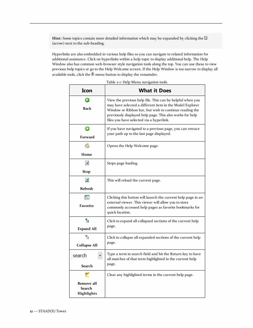
Hint: Some topics contain more detailed information which may be expanded by clicking the(arrow) next to the sub-heading.
Hyperlinks are also embedded in various help files so you can navigate to related information foradditional assistance. Click on hyperlinks within a help topic to display additional help. The HelpWindow also has common web-browser style navigation tools along the top. You can use these to viewprevious help topics or go to the Help Welcome screen. If the Help Window is too narrow to display allavailable tools, click the menu button to display the remainder.
Icon What it Does
Back
View the previous help file. This can be helpful when youmay have selected a different item in the Model ExplorerWindow or Ribbon bar, but wish to continue reading thepreviously displayed help page. This also works for helpfiles you have selected via a hyperlink.
Forward
If you have navigated to a previous page, you can retraceyour path up to the last page displayed.
Home
Opens the Help Welcome page.
Stop
Stops page loading.
Refresh
This will reload the current page.
Favorite
Clicking this button will launch the current help page in anexternal viewer. This viewer will allow you to storecommonly accessed help pages as favorite bookmarks forquick location.
Expand All
Click to expand all collapsed sections of the current helppage.
Collapse All
Click to collapse all expanded sections of the current helppage.
Search
Type a term in search field and hit the Return key to haveall matches of that term highlighted in the current helppage.
Remove allSearch
Highlights
Clear any highlighted terms in the current help page.
Table 2-1: Help Menu navigation tools.
12— STAAD(X) Tower

Output paneGeometry tables, analysis messages/warnings/errors, code check messages/warnings/errors, and designresults will be displayed here.
Text messages and reports will be displayed here, providing you with information when the program isrunning an analysis or design.
Hint: Pay close attention toWarning and Error messages displayed here. They will help you isolate anyissues with your tower model.
Note: Detailed results of these actions will be found in the Results ribbon tab and theModel> Analysis > Results section of the Tower Model Explorer pane.
Tables
STAAD(X) Tower can display model data in tabular format for easy review and editing. You may displaytables for items via their pop-up menu found in the Tower Model Explorer Window. See "Using Tables" onpage 16 for additional information.
Hint: Some of the most commonly used tables are also accessible from the Model ribbon tab.
Report Building Panels
When you click on the Report ribbon tab, the Tower Model Explorer is replaced by a pair of panels usedreport building. These two panels represent the list of all available report entities —the Report DocumentMap— and those which you want to include in the report output — the Selected Items List.
User Manual — 13
Chapter 2 Getting Started
2.2 A Tour of the STAAD(X) Tower Environment

2.3 Units in STAAD(X) TowerWhen you begin a new model file in STAAD(X) Tower, you select default units of length and force. Whenyou must use different units for length or force than the defaults, you will simply type them in theappropriate fields in the properties panel. When typing a value in any field, simply add a space and thentype the abbreviation for the desired units (see the following table for available units).
Additionally, you can set derived units differently than base units. For example, if you want to typicallywork in feet and kips, you will still set the units for pressure as pounds (force) per square foot andmoment as inch-kips. Then, in one instance it is more convenient to enter a moment in foot-kips, you cansimply include the non-default units.
Hint: To access a list of available units for a given property field, simply right click in the field. Thenselect the units you want to use from the pop-up menu.
Warning: Changing a unit type in STAAD(X) Tower does not change any existing value's units in themodel. This only changes the default units in the interface.
Units of Length Units of Force
Unit Abbreviation Unit Abbreviation
inch in or " pound (force) lbf
foot ft or ' pound (mass) lb
millimeter mm kilopound kip
yard yd kilogram kg
centimeter cm metric ton Mton
Table 2-2: Available units of Length and Force in STAAD(X) Tower
14— STAAD(X) Tower

Units of Length Units of Force
Unit Abbreviation Unit Abbreviation
decimeter dm newton N
meter m decanewton DN
kilometer km kilonewton kN
mile mil meganewton MN
Note: Some fields have units already specified and these will indicated as such. For these fields, simplyprovide a magnitude with no units.
2.4 Coordinates in STAAD(X) TowerSTAAD(X) Tower uses a conventional Cartesian coordinate system, with the global Y axis assumed asvertical (i.e., the height of the tower is parallel to the global Y axis). This coordinate system is a rectangularcoordinate system (X, Y, Z) which follows the orthogonal right hand rule. This coordinate systemmay beused to define the joint locations and loading directions. The translational degrees of freedom are denotedby u
1, u2, u3and the rotational degrees of freedom are denoted by u
4, u5& u
6.
Degrees of freedom as used in STAAD(X) Tower
A STAAD(X) Tower model with global coordinate axis labeled
User Manual — 15
Chapter 2 Getting Started
2.4 Coordinates in STAAD(X) Tower

2.5 Using TablesTables are opened in the Output pane and can be used to sort model data as well as to edit the geometrydata as well as to verify the integrity checks.
Hint: Some commonly used model input and results tables can be displayed from the Tables drop-down menu tool found on the Model ribbon tab.
Areas of the Output pane
A. Property Column headings
B. Filter Row
C. Model Data Rows (Sorted and Filtered by input)
D. Filter Option Field
E. Output Window tabs (containing all open tabs and the output window)
Selecting a element or load in the table
1. (Optional) Scroll, filter, or sort the table as necessary to locate the desired model element orload.
2. Click the selector found at the left side of the desired model element row.
A icon is displayed in the selector field. The row is highlighted in the table and thecorresponding model element is highlighted in theView pane.
Filtering table rows
You can the rows in a table to those with column data which matches some criteria.
The first row of a table (marked with a ) is used to filter the rows that display by matching columnvalues.
16— STAAD(X) Tower

1. Click the top cell for the Property column for which you want to sort.
2. Begin typing the desired filter value.
or
Select the Filtering drop-down (the icon) in the top, right hand corner of the PropertyColumn heading and select an existing value from the menu.
The table rows with matching values remain while non-matching rows are removed.
Hint: Partial matches are possible with the left-most characters in the filter cells.
3. Additional filters may be entered as needed.
Current filter values are displayed in an option field at the bottom of the filtered table.
Clearing a table filter
1. Click the close icon (red X) on the left hand side of the filter option field.
or
Clear all of the fields in the filter row.
or
Select All from the filter drop-down list.
Sorting a table by a column
Tables are initially sorted by the first column in ascending order (typically Member or Node number).
1. Click the Property Column heading corresponding to the property
The table is re-ordered, sorting rows by ascending values of the selected Property Column.
2. Click the same Property Column heading again to sort values in a descending order.
2.6 Making SelectionsThe parametric modeling facilities in STAAD(X) Tower can result in fairly complex models with very littleinput. However, even for highly complex models, STAAD(X) makes it easy to select just the entities youwant. The first step is to choose what class of entities you need to select, by clicking on the appropriateSelection tools. You can have more than one type of selection pointer highlighted at once.
There are a number of ways in STAAD(X) to select entities:
n Here, entities are simply selected, one by one. You can also hold down the Ctrl key whilemaking selections to select multiple entities. This method works well if entities are spreadabout the model.
User Manual — 17
Chapter 2 Getting Started
2.6 Making Selections

n Simply click and hold the left mouse button and drag the pointer diagonally (any direction).You will notice a rectangle forming on screen which is dynamically updated as the pointermoves. Any entity which is contained in this rectangle will be selected for you upon releasingthe mouse button. This method works well for entities which are grouped together in onelocation in the model.
Note: Multiple selection tools may be toggled on simultaneously to select different types of modelentities at the same time.
18— STAAD(X) Tower

Chapter 3
Geometry Generation
Creating a new tower model is done by using one of the parametric set-up wizards included withinSTAAD(X) Tower. These easy-to-use yet powerful wizards allow you to create general tower structureswhich you can then modify as necessary.
3.1 Understanding Sections and Panels 19
3.2 Creating a new tower model 20
3.3 Monopole Wizard 21
3.4 Self-Supporting Tower Wizard 29
3.5 Guyed Tower wizard 33
3.6 Editing Tower Geometry 41
3.1 Understanding Sections and PanelsThe overall geometry of a self-supporting towers can be defined either by the total number of panelsalong the tower height or by the number of sections.
User Manual — 19

A panel is a superset of members consisting the leg members, diagonal members, horizontal members,and redundant members along the panel top. A panel height represents one bay of bracing, which isparametrically defined by a bracing pattern.
A section represents a superset of panels. Using sections allows you to control the panel parameters formultiple panels simultaneously. Parameters such as panel slope (i.e., tapered or straight) and bracingpatterns can be selected for all the panels within a section. Additionally, you can edit the number of bayswithin a section to vary the height of panels from section to section. Physical leg members areautomatically split at divisions between sections, allowing you to vary leg member profiles along theheight of the tower structure.
3.2 Creating a new tower modelNew tower models are created by either using a parametric wizard or by a previously saved templatefile.
1. Select New from the STAAD(X) Menu.
The Setup Wizard page opens.
20— STAAD(X) Tower
2. Select one of the three options for tower type. STAAD(X) Tower supports three different basictypes of tower structures from the wizard. Each of these choices will take you to a differentwizard to create that general tower type.
l Monopole: stepped, tapered, and tapered with round extension
l Self-supporting: three-legged or four-legged
l Guyed: three-legged or four-legged
3. ClickNext > to proceed to the parametric wizard or to select the template file.
4. Complete the parametric model wizard as detailed in the following sections.
5. You can now edit your base tower model as necessary and proceed to add loads, components,etc. before performing an analysis.
Hint: Now is a good time to take a moment to save your model. To do so, click either the(Save) button found on the Home tab of the ribbon menu (also found on the STAAD(X)menu). You will be prompted to choose a location on your storage devices to save the file andto specify a file name.
3.3 Monopole WizardThis set of dialogs will walk you step-by-step through the creation of generating a freestanding, monopoletower structure. You can change the details of the tower once the wizard has finished in the STAAD(X)Tower interface.
User Manual — 21
Chapter 3 Geometry Generation
3.3 Monopole Wizard
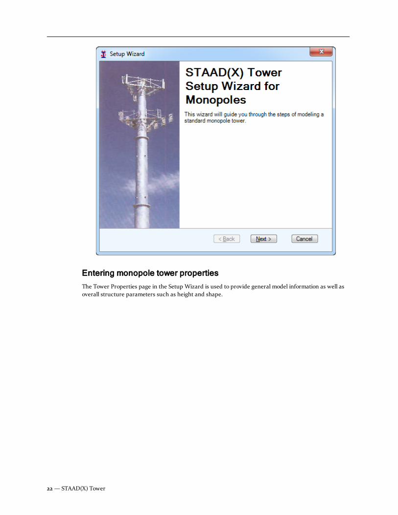
Entering monopole tower properties
The Tower Properties page in the Setup Wizard is used to provide general model information as well asoverall structure parameters such as height and shape.
22— STAAD(X) Tower

User Manual — 23
Chapter 3 Geometry Generation
3.3 Monopole Wizard

1. Specify the general Tower Properties:
ParameterName
Description
Tower Name Type a name of the tower model. You canuse any alpha-numeric combination for thisfield.
Tower Description (Optional) Type a brief description of themodel. You can use any alpha-numericcombination for this field.
Unit Type Select the system of units:
l English
l Metric
Country Code Select the country in which the governingstandards are used:
l US (for EIA/TIA-222-F and TIA-222-G codes)
l Indian (for IS 802,806 codes)
Design Code Select the design code standard to be used.Options available are dependant on theselected Country Code.
Note: Only US Standards TIA-222-G andEIA/TIA-222-F are applicable formonopole design. The analysis anddesign per TIA-222-G addendum 1 and 2(resistance factor for compression isdifferent in addendum 1 and effectiveyield stresses are different in addendum2) cannot be performed.
Length and Force units Based on the Unit Type you have chosen,provide the units of both length and forceyou want to use as defaults for the project.For any field in which you do not explicitlyprovide units, these will be used.
Table 3-1: General Tower parameters
2. Specify the Monopole Tower Properties:
24— STAAD(X) Tower

ParameterName
Description
Type of Monopole Select either:
l Stepped (i.e., a straight monopolewith a constant diameter ordiameter change at intervals alongthe height of the tower), or
l Tapered (i.e., tapers downlinearly along its height).
Elevation at Base Type the elevation above surrounding terrain.This is used to calculate the appropriate windforces along the height of the tower.
Height of Tower Type the total height of the tower modelabove its base.
Number of Sections Type the number of sections along the height.This must be an integer.
Number of Sides (Tapered type monopoles) Select the cross-section type by number of facets. For steppedmonopole sections, the cross section is alwaysround.
Round MonopoleExtension
Set this option to designate one or more top-most sections as a round tube for Taperedmonoples.
Table 3-2: Monopole Tower parameters
3. ClickNext > to continue.
Entering monopole structural properties
The Structural Properties page of the Setup Wizard is used to provide cross section information, support,and load data.
User Manual — 25
Chapter 3 Geometry Generation
3.3 Monopole Wizard

26— STAAD(X) Tower

1. Specify the Member Properties for the type of monopole tower selected on the previous page:
ParameterName
Description
Type of Section Select either Pipe or Rod type section.Alternately, you may select None in thewizard and specify a section from the maininterface.
Note: Stepped monopoles design can beperformed using only pipe sections fromAISC 13th Edition, Table 1-4.
Default Section Used the drop-down list to select a defaultPipe or HSS section to be used. The Outerand Inner diameter values are displayed forthe selected section.
Steel Grade Select the corresponding steel grade for theselected section.
Material and Grade Select the defaultMaterial and material Gradefor the round monopole structure.
Table 3-3: Member Properties: Stepped Monopole parameters
ParameterName
Description
Type of Section For Stepped monopoles, specify either a pre-defined Tapered Tube or select None in thewizard and specify a section from the maininterface.
Depth/Dia of Tube attop
Specify the diameter of the tapered tube atthe top of the monopole structure. These canbe edited in the General Tower Propertieslater, if necessary.
Tube Thickness attop/base
Specify the tube thickness to be used at boththe top and base of the monopole structure.
Galvanizing Thickness Specify a uniform galvanization coatingthickness. Enter zero if non-galvanized or tobe ignored.
Table 3-4: Member Properties: Tapered Monopole parameters
User Manual — 27
Chapter 3 Geometry Generation
3.3 Monopole Wizard

ParameterName
Description
Tapered Factor Specify a slope factor for the change in outerdiameter per unit of height. This can beedited in the General Tower Properties later,if necessary.
Material and Grade Select the defaultMaterial and material Gradefor the tapered monopole structure.
No. of Extensions Select the number of extension segments touse for the round monopole extension.
2. Specify the Support conditions for the base level node. A Support assigned from theparametric wizard must be of a Fixed type. If other supports types (i.e., enforceddisplacement or partially fixed) are required, select None. These may be specified andapplied in the main interface.
3. Select optional selfweight self-weight load and parameters.
ParameterName
Description
Apply self-weight load Set this option if you want to apply selfweightloads to all members.
Direction Specify the direction in which the selfweightis to be applied (Y is default).
Factor Specify the factor for the applied selfweightload.
Include Components Select this check box if the dead load of theexternal components attached should beincluded along with the dead load of thestructure.
Table 3-5: Load parameters
4. Once you are finished with this page, select the Next tool to continue.
A summary page is presented which displays the description of the tower properties for themodel generated based on the input provided. You may select the < Back tool at any time tochange the input.
5. Once you are ready for the structure to be created, select the OK tool.
The model is displayed in a new tab of the view window in the main program interface. Theprogram automatically calculates the section length, section thickness, and lap splice basedon information entered into the wizard. You can review and edit these values in the PoleSections table.
28— STAAD(X) Tower

3.4 Self-Supporting Tower WizardThese screens will take you step-by-step through generating a three- or four-legged, self-supporting towerstructure. A wide variety of common tower bracing patterns are available as templates. You can generateyour own bracing pattern during this process as well. You can also change the details of the tower oncethe wizard has finished in the STAAD(X) Tower interface.
Entering self-supporting tower properties
The Tower Properties page in the Setup Wizard is used to provide general model information as well asoverall structure parameters such as height and shape.
The Tower Properties dialog box in the Self-Supporting Tower wizard
User Manual — 29
Chapter 3 Geometry Generation
3.4 Self-Supporting Tower Wizard

1. Specify the General Tower properties:
ParameterName
Description
Tower Name Type a name of the tower model. You canuse any alpha-numeric combination for thisfield.
Description (Optional) Type a brief description of themodel. You can use any alpha-numericcombination for this field.
Type of Unit You must select between the English andMetric system of units (default is English).
Country Code This specifies the country for code checkingand section databases. Select the country ofthe design code (default is US).
Design Code Select the country in which the governingstandards are used:
l US (for EIA/TIA-222-F and TIA-222-G codes)
l Indian (for IS 802,806 codes)
Length and Force units Based on the Unit Type you have chosen,provide the units of both length and forceyou want to use as defaults for the project.For any field in which you do not explicitlyprovide units, these will be used (default isfeet and kilopound, respectively).
Table 3-6: General Tower parameters
2. Base Tower Properties:
ParameterName
Description
Number of Legs Select between a square, four-legged andtriangular, three-legged tower structure(default is four).
Elevation at Base Provide the elevation above surroundingterrain. This is used to calculate theappropriate wind forces along the height ofthe tower.
Table 3-7: Base Tower parameters
30— STAAD(X) Tower

ParameterName
Description
Height of Tower Provide the total height of the tower modelabove its base.
Base and Top FaceWidth
The face width is the distance betweenadjacent legs. Provide the width at thebottom of the lowest panel and the top of thehighest panel in these fields, respectively.
Constant Slope Select this option to taper the entirestructure. If this box is unchecked, the toppanel of the tower will be straight, with therest of the panels being tapered.
Type of Configuration Select either Sections or Panels.
Number ofPanels/Sections
Specify the total number of panels orsections along the height, depending on theConfiguration type selected.
Bays per Section (Section Configuration only) Specify thenumber of panel bays within each section.
Horizontals Select this box if horizontal members arepresent at the top of each panel.
Default Bracing Type Select the typical bracing pattern you wantto apply for all panel faces by default. Youcan edit individual panel faces or levels asneeded once the wizard is finished. You alsohave the option to generate custom bracingpatterns and save them for re-use.
3. ClickNext to continue.
User Manual — 31
Chapter 3 Geometry Generation
3.4 Self-Supporting Tower Wizard

Entering self-supporting tower structural propertiesThe Structural Properties dialog box in the Self-Supporting Tower wizard
1. Member Properties for Leg, Horizontal, and Diagonal (Bracing) Members. For each membertype present in the tower structure, specify the following for the default member profile andmaterial:
ParameterName
Description
Specification Select the catalog from which you want toselect shapes. The title of each availablespecification indicates the publisher andversion.
Shape Select a section shape classification from thelist (different shapes are available fromdifferent specifications).
Designation Select the section to be used from the withinthe specification and shape selection.
Steel Grade Select the corresponding steel grade for theselected section.
Table 3-8: <type> Member parameters
32— STAAD(X) Tower

2. Specification - Select this option if you want to consider all diagonal members as truss i.e.,fully pinned-end) members.
3. Support - Specify the support conditions for all base level nodes. Supports assigned from theparametric wizard can either be fully Fixed or Pinned (fixed is default). If other supportstypes (i.e., enforced displacement or partially fixed) are required, select None. These may bespecified and applied in the main interface.
4. Apply Selfwieght Load - Select this box if you want to apply selfweight loads to all members.If checked, click the expand icon to edit the following required parameters:
ParameterName
Description
Direction Specify the direction in which the selfweightis to be applied (Y is default).
Factor Specify the factor for the applied selfweightload.
Include Components Select this check box if the dead load of theexternal components attached should beincluded along with the dead load of thestructure.
Table 3-9: Load parameters
5. Once you are finished with this page, clickNext to continue.
A summary page is presented which displays the description of the tower properties for themodel generated based on the input provided. You may select the < Back tool at any time tochange the input.
6. Once you are ready for the structure to be created, clickOK.
The model is displayed in a new tab of the view window in the main program interface. Youcan now proceed to editing the tower geometry.
3.5 Guyed Tower wizardThese screens will take you step-by-step through the creation of generating guyed tower structure. Youcan change the details of the tower once the wizard has finished in the STAAD(X) Tower interface.
Entering guyed tower properties
Delete this text and replace it with your own content.
User Manual — 33
Chapter 3 Geometry Generation
3.5 Guyed Tower wizard

34— STAAD(X) Tower
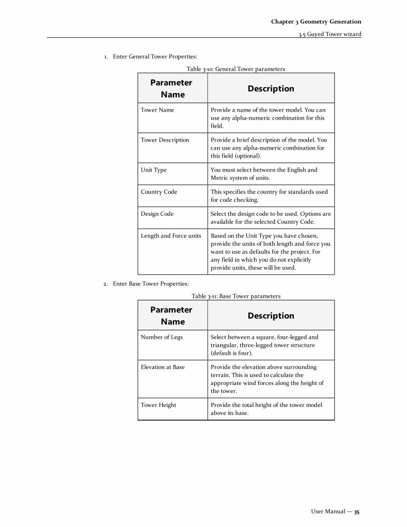
1. Enter General Tower Properties:
ParameterName
Description
Tower Name Provide a name of the tower model. You canuse any alpha-numeric combination for thisfield.
Tower Description Provide a brief description of the model. Youcan use any alpha-numeric combination forthis field (optional).
Unit Type You must select between the English andMetric system of units.
Country Code This specifies the country for standards usedfor code checking.
Design Code Select the design code to be used. Options areavailable for the selected Country Code.
Length and Force units Based on the Unit Type you have chosen,provide the units of both length and force youwant to use as defaults for the project. Forany field in which you do not explicitlyprovide units, these will be used.
Table 3-10: General Tower parameters
2. Enter Base Tower Properties:
ParameterName
Description
Number of Legs Select between a square, four-legged andtriangular, three-legged tower structure(default is four).
Elevation at Base Provide the elevation above surroundingterrain. This is used to calculate theappropriate wind forces along the height ofthe tower.
Tower Height Provide the total height of the tower modelabove its base.
Table 3-11: Base Tower parameters
User Manual — 35
Chapter 3 Geometry Generation
3.5 Guyed Tower wizard

ParameterName
Description
Base and Top FaceWidth
The face width is the distance betweenadjacent legs. Provide the width at the bottomof the lowest panel and the top of the highestpanel in these fields, respectively. The towerlegs slope linearly between these two widthson each face.
Tapered at Base Select this option if tower model tapers to asingle support at the base level.
Horizontals Select this option if horizontal members arepresent at the top of each panel.
Number of Panels Specify the total number of panels along theheight.
Tapered Panels Specify the number of tapered panels at thebase of the tower if the tapered option hasbeen selected above.
Default Bracing Type Select the typical bracing pattern you want toapply for all panel faces by default. You canedit individual panel faces or levels as neededonce the wizard is finished. You also have theoption to generate custom bracing patternsand save them for re-use.
3. Select the Next > tool to continue.
Entering guy properties
Guy Properties
Note: The initial tension of guy cables cannot be defined; by default the application considers thesame as zero. The catenary approach was followed to evaluate the internal cable member forces. Thevalue of the forces may differ for any other approach.
36— STAAD(X) Tower
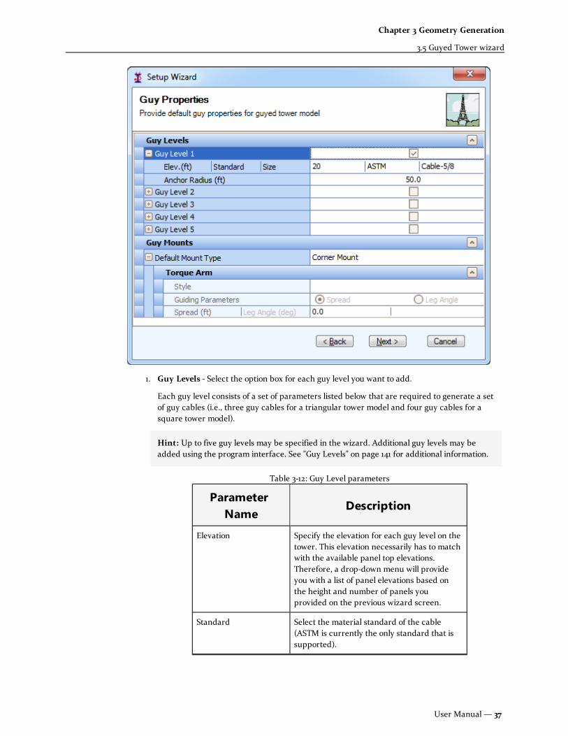
1. Guy Levels - Select the option box for each guy level you want to add.
Each guy level consists of a set of parameters listed below that are required to generate a setof guy cables (i.e., three guy cables for a triangular tower model and four guy cables for asquare tower model).
Hint: Up to five guy levels may be specified in the wizard. Additional guy levels may beadded using the program interface. See "Guy Levels" on page 141 for additional information.
ParameterName
Description
Elevation Specify the elevation for each guy level on thetower. This elevation necessarily has to matchwith the available panel top elevations.Therefore, a drop-down menu will provideyou with a list of panel elevations based onthe height and number of panels youprovided on the previous wizard screen.
Standard Select the material standard of the cable(ASTM is currently the only standard that issupported).
Table 3-12: Guy Level parameters
User Manual — 37
Chapter 3 Geometry Generation
3.5 Guyed Tower wizard

ParameterName
Description
Size Select a nominal diameter size for the guycables from the available list of standardcables for the selected standard.
Anchor Radius Specify the radius of guy anchors at baseelevation level, as measured from the centerof the tower structure to the anchor node ofthe guy. Anchor radius can be varied for eachguy level included.
2. Guy Mounts - Select the Default Mount Type you want to use for this model.
Hint: Mounts may be changed individually in the main program interface. See "Guy Mounttypes" on page 143 for information on mount types.
3. If you selected either Torque Arm Corner or Star Mount in the default type, you mustprovide additional structural details for the torque arm.
See Torque Arm options below. See "Torque Arm styles" on page 147 for more information.
l Wing - Forms a isosceles triangle parallel to the tower leg, centered over twopanel heights.
l Bat Ear - Forms a right-angle triangle with the height of one panel and ahorizontal arm at the top of that panel.
l Dog Ear - Forms a right-angle triangle with the height of one panel and ahorizontal arm at the bottom of that panel.
l Cantilever - A single cantilevered member is used at the panel height specified.
4. (Torque Arm only) Guiding Parameters -
l Spread - Specify the distance between the tips of the adjacent torque arms.
l Leg Angle - Currently not supported.
5. ClickNext > to continue.
38— STAAD(X) Tower

Entering guyed structural properties
User Manual — 39
Chapter 3 Geometry Generation
3.5 Guyed Tower wizard

1. Length of Section
ParameterName
Description
Maximum PermissibleLength
You can enter the maximum permissiblelength for any physical member in themodel. Typically, this will be used to limit thelength of tower leg members. The parametricmodel generation process will ensure thatany physical member's length that wouldhave exceeded this limit will be split intomultiple physical members. To remove thisrestriction, simply specify this value as zero(0).
Note: Tower leg divisions can beassigned by using the Split Physical LegMembers tool after the Setup Wizard iscomplete.
Table 3-13: Length of Section parameters
2. Member Properties - For Leg, Horizontal, Diagonal (Bracing), Guy Pull Off, and GuyDiagonal Member types present in the tower structure, specify the following for the defaultmember profile and material:
ParameterName
Description
Type of Section Specify either Angle or Pipe type section.Alternately, you may select None in thewizard and specify a section from the maininterface.
Section Size Select the section to be used from the withinthe section type specified.
Steel Grade Select the corresponding steel grade for theselected section.
Table 3-14: <type> Member parameters
3. Specification - Select this check box if you want to consider all diagonal members as trussi.e., fully pinned-end) members.
4. Support - Specify the support conditions for all base level nodes. Supports assigned from theparametric wizard can either be fully Fixed or Pinned (fixed is default). If other supportstypes (i.e., enforced displacement or partially fixed) are required, select None. These may bespecified and applied in the main interface.
40— STAAD(X) Tower

Similarly, the Anchor Node supports must be specified as either Pinned (default) or none, withthe latter used if you want to specify some other condition in the main interface.
5. Load - Select this box if you want to apply selfweight loads to all members. If checked, thefollowing parameters are required:
ParameterName
Description
Direction Specify the direction in which the selfweightis to be applied (Y is default).
Factor Specify the factor for the applied selfweightload.
Include Components Select this check box if the dead load of theexternal components attached should beincluded along with the dead load of thestructure.
Table 3-15: Load parameters
6. Once you are finished with this page, clickNext to continue.
A summary page is presented which displays the description of the tower properties for themodel generated based on the input provided. You may select the < Back tool at any time tochange the input.
7. Once you are ready for the structure to be created, clickOK.
The model is displayed in a new tab of the view window in the main program interface.
3.6 Editing Tower GeometryOnce you've added the basic tower geometry using a wizard, you'll often need to edit some of the detailsfor various panels or sections. These edits can be accomplished using either the Panels or Sections tablefor either Self-Supporting or Monopole towers, respectively.
Displaying the panels table
For Self-Supporting Tower structures, you can display the panels table. This table can be used forreviewing and editing tower geometry in one place, panel by panel.
1. Right click on theModel > Physical Model > Objects > Panels section of the Tower ModelExplorer.
2. Select Show Self-Supported Panels Table from the pop-up menu.
The Panels table opens in the Output pane.
User Manual — 41
Chapter 3 Geometry Generation
3.6 Editing Tower Geometry

Displaying the sections table
For Self-Supporting Tower structures, you can display the sections table. This table can be used forreviewing and editing tower geometry in one place by tower section.
1. Right click on theModel > Physical Model > Objects > Sections section of the TowerModel Explorer.
2. Select Show Sections Table from the pop-up menu.
The Sections table opens in the Output pane.
Display the pole sections table
For Monopole Tower structures, you can display the pole sections table. This table can be used forreviewing and editing tower geometry in one place.
1. Right click on theModel > Physical Model > Objects > Sections section of the TowerModel Explorer.
2. Select Show Pole Sections Table from the pop-up menu.
The Pole Sections table opens in the Output pane.
Note: Cells containing white backgrounds may be edited (shaded cells are non-editable).
Breaking physical leg members at a selected height
By default, physical leg members are considered as a continuous, straight member. Breaks are added atchanges in slope (such as from a tapered panel to a straight panel). Additional breaks can be added toaccommodate changes in section at a leg splice.
1. Select the Split Physical Leg Members tool on the Tools ribbon tab.
The Split Tower Leg Members dialog box opens.
2. Select either the Panel End tab (for splitting at the top of a panel) or the Custom tab (forsplitting at any arbitrary elevation).
3. Select either the Panel ID or specify an elevation.
or
Specify a height along the global Y axis at which the split is to be added.
4. Select the Add tool.
The split definition is added to the Elevations list.
5. Repeat steps 2 through 4 to add as many tower leg splits as needed.
6. Select the Done tool.
Adding a hip member
You can add out-of-plane members to a lattice tower structure using the following procedure.
42— STAAD(X) Tower
Before you beginIf you want to use a different section profile than other members for a hip bracing member, then you maywant to use the Structure Property Catalog tool to add that section.
1. Select the Select Node tool on the Model ribbon tab.
The mouse pointer changes to the Nodes cursor.
2. Zoom into the area in the View pane where you want to add a member and select the twoexisting nodes which will form the start and end nodes. Note their numbers from either thetool tip or the Properties pane.
Hint: You will quickly identify the number pattern and be able to add additional memberswithout the need to switch back to this tool.
3. Select the Add Hip Member tool on the Tools ribbon tab.
The Add Hip Bracing Member dialog box opens.
4. Select aMember Typewhich best describes the use of the member.
Note: The member's orientation is checked against the selected member type to verify theappropriate selection (i.e., end nodes with the same X and Z coordinates cannot be specifiedfor a horizontal).
5. Select the Panel No. in which the member is to be added.
The Start Node and End Node lists are updated with the node numbers contained within theselected panel.
6. Select a Start Node and End Node to define the member orientation within the panel.
7. Select a Section Profile from the list of current profiles in the tower model.
8. ClickOK.
The dialog closes and the member is added to the model.
User Manual — 43
Chapter 3 Geometry Generation
3.6 Editing Tower Geometry

44— STAAD(X) Tower
Chapter 3
3.6 Editing Tower Geometry

Chapter 4
Load Generation
STAAD(X) Tower includes both automatic and manual load application methods for creating towermodels.
4.1 Understanding Loads in STAAD(X) Tower 45
4.2 Working with Tower Components 46
4.3 Manually Adding Lateral Loads 49
4.4 Creating primary load cases 51
4.1 Understanding Loads in STAAD(X) TowerSTAAD(X) Tower has facilities for manually applying joint and member loads as well as for the automaticgeneration of code-specified loads.
Definitions
Definitions contain the options through which you specify parameters for a code load, such as wind orseismic.
User Manual — 45

See "Wind/ Ice Loads" on page 185
See "Seismic Loads" on page 186
Load Groups
A load group is a set of explicitly defined reference loads, presumably from the same physical source.Each of these explicitly defined loads is referred to as a Load Item (e.g., joint load, member load,wind/ice loads, seismic loads, etc.).
Some examples of a how a load group would be used are:
l All dead load on a structure (this is typically an automatically generated load groupcontaining the selfweight)
l Wind + ice load on a structure from a 45° azimuth
l Seismic load in the North-South direction
Load Items
Individual physical loads are added as load items within a user-generated load group. STAAD(X) Towerallows you to added manual load items, such as joint or member loads, as well as code-defined loadswhich are collected as a single load item.
See "Joint Load" on page 180 for information on adding and assigning joint loads.
See "Member Loads" on page 181 for information on adding and assigning member loads,including uniform, varying, and concentrated loads.
Load items must be "applied" to the structural model before they are considered to be active.
Primary Load Cases
A primary load case is a algebraic combination of Load Groups which is passed to the analysis engineduring the analysis of the model.
Note: Only load data which is included in one or more Primary Load Cases is included in the analysis.
4.2 Working with Tower ComponentsOne of the most important factors in loading a tower structure comes from the component weight as wellas their additional effective wind area. You can add component support sub-structures parametrically toyour model and quickly select the component types these sub-structures support. This allows you toquickly and easily model complex communication tower assemblies.
Adding a component mount
Component mounts are used to support various components such as antennas or shields.
46— STAAD(X) Tower

1. Either
l Select one of the mount tools from the Discrete Appurtenance (Mounts) group onthe Components tab.
or
l Right click on the Physical Model > Objects > Components > Mounts entry inthe Tower Model Explorer pane and then select the type of mount you want to addfrom the pop-up menu.
A new mount with default appurtenances is added to the model at an arbitrary height. Theproperties of the mount are displayed in the Properties pane.
2. In the mount Properties panel, Type the actual Elevation where the mount is located.
The view updates.
3. (Optional) For T-Arm and Side Armmounts, select the number of mounts included at thisheight.
Hint: You can specify the legs to which these are mounted by editing the Orientation of theindividual mount components.
The selected mount type is now added to the model. However, it is likely that you will want to modify someof the individual mount or antenna component properties next.
Adding tower mounted amplifiers to panel antennas
Tower mounted amplifiers (TMA) are added to individual panel antennas via their properties.
Your tower model must have at least one panel antenna in order to add TMAs
1. Select the panel antenna to which you wish to add one or more TMAs by either:
l Expand the Physical Model > Objects > Components > … > Mount Pipe #> section of the Tower Model Explorer pane
or
l Use the Select Panel Antenna tool in the View pane
The Appurtenance Properties for the panel antenna are displayed in the Properties pane.
2. Select the No of TMA in the properties.
Hint: Up to six amplifiers may be added to a single panel antenna.
The TMAs are added as child elements to the selected panel antenna in the Tower ModelExplorer pane.
You can now select any of the newly added TMAs to edit its properties.
Adding a work platform
Work platforms can be added or Self-Supporting Towers or Guyed Towers only.
User Manual — 47
Chapter 4 Load Generation
4.2 Working with Tower Components

1. From the Components ribbon tab, select the Platform tool (found in the Add Componentsgroup).
A Platform entry is added in the Tower Model Explorer pane.
2. Select the platform you want to edit from either theModel > Physical Model > Objects> Components > Platforms section of the Tower Model Explorer or from the View paneusing the platform selection cursor.
The platform is highlighted in both areas of the interface. The platform parameters aredisplayed in the Properties pane.
3. Edit the Elevation Above Base value to add the Platform to the tower model.
4. Edit the platform parameters to manipulate the shape, structure, and type of platformpresent.
5. Specify values of the Projected Area and Weight Properties.
Adding a feed line
1. From the Components ribbon tab, select the Feed Line tool (found in the Add Componentsgroup).
or
Right click on theModel > Physical Model > Objects > Components > Feed Linessection of the Tower Model Explorerpane and select Add Feed Line from the pop-up menu.
A Feed Line entry is added in the Tower Model Explorer pane.
Note: You must edit the feed line definition to specify start and end heights for the feedline to be added to the tower for analysis and design.
2. Select the feed line you want to edit from either theModel > Physical Model > Objects> Components > Feed Lines section of the Tower Model Explorer or from the View paneusing the feed lines selection cursor.
The feed line is highlighted in both areas of the interface. The feed line parameters aredisplayed in the Properties pane.
3. Select a Coax Cable definition from the library.
Note: Custom coax data can be added to the program using the Feed Line Shapes: CoaxialCables dialog.
4. Edit the Start Height and End Height values to add the Feed Line to the tower model.
5. Select the Face ID from the drop-down list.
6. Select either Outside or Inside of the tower for the Position of the feed line.
7. Edit the feed line arrangement and other feed line properties as necessary.
48— STAAD(X) Tower
Adding a ladder
1. From the Components ribbon tab, select the Ladder tool (found in the Add Componentsgroup).
or
Right click on theModel > Physical Model > Objects > Components > Ladders section ofthe Tower Model Explorer and select Add Ladder from the pop-up menu.
A Ladder entry is added in the Tower Model Explorer pane.
Note: You must edit the ladder definition to specify start and end heights for the ladder tobe added to the tower for analysis and design.
2. Select the platform you want to edit from either theModel > Physical Model > Objects> Components > Ladders section of the Tower Model Explorer or from the View pane usingthe ladder selection cursor.
The ladder is highlighted in both areas of the interface. The ladder parameters are displayedin the Properties pane.
3. Edit the Start Height and End Height values to add the Ladder to the tower model.
4. Select the Face ID option to place the ladder on a specific face of the tower.
5. Select either Outside or Inside of the tower for the Position of the ladder.
Deleting a component
1. Select the tower component you want to delete from either theModel > Physical Model> Objects > Components … section of the Tower Model Explorer or from the View pane usingthe ladder selection cursor.
2. Click (Delete) on the Model ribbon tab.
4.3 Manually Adding Lateral LoadsWind and seismic loads are defined and applied from the Tower Model Explorer pane.
Adding a wind/ice load per TIA/EIA-222
1. Right click on theModel > Objects > Loads > Load Generation Parameters section of theTower Model Explorer pane and select Add Wind/Ice Parameters from the pop-up menu.
2. Select which definition type you want to provide from the sub-menu:
User Manual — 49
Chapter 4 Load Generation
4.3 Manually Adding Lateral Loads

l TIA/EIA[222F] Definition
l TIA/EIA[222G] Definition
The wind/ice definition is added to the Load Generation Parameters list and selected forediting.
3. Select the new definition entry.
The properties are shown in the Properties pane.
4. Select the Zone Identification (State and County).
The Basic Wind Speed for the tower's location is populated.
5. (Optional) Select the option to include Ice Load and specify Type of Ice, Ice Density, IceThickness, and ice load Wind Speed parameters as needed.
6. Select the Load Case options (wind only, wind and ice, service wind) you want to include inthe model by selecting the check box associated with each.
When selected, the load case is added to theModel > Objects > Loads > Load Groupssection of the Tower Model Explorer.
Hint: Once you have selected a load case to be added to the model, un-selecting the casewill not remove it. Selecting the same load case again will add a duplicate to the model.Refer to deleting a load case.
7. Assign each of the wind/ice loads to the structure by right-clicking the load entry andselecting Assign from the pop-up menu.
Hint: Nomember selection is necessary as wind/ice loads are assigned to the entirestructure.
Assinging wind loads per ASCE 7
1. Right click on theModel > Objects > Loads > Load Generation Parameters section of theTower Model Explorer.
2. From the pop-up menu, select Add Wind/Ice Parameters > Wind Definition.
The wind intensity definition is added to the Load Generation Parameters list and selected foradding height/intensity pairs to the table.
3. Add as many height and intensity pair values as necessary to the table to describe the windprofile.
4. Right click on theModel > Objects > Loads > Load Groups section of the Tower ModelExplorer.
5. From the pop-up menu, select Add Load Group.
A new load group is added to the Load Groups list.
6. Right click on the new load group entry and selectWind/Ice Load > Add Wind Load onOpen Structure from the pop-up menu.
The Wind [Open Structure] load is added to the Load Group and selected for editing.
50— STAAD(X) Tower

7. (Optional) Select the Wind Load Definition to be used with this Load Group (if multipledefinitions are present) and edit Type and Overall Factor parameters if necessary.
8. Assign Direction Vector values to describe the wind azimuth.
9. Assign the wind load to the structure by right-clicking the load entry and selecting Assign fromthe pop-up menu.
Hint: Nomember selection is necessary as wind loads are assigned to the entire structure.
Adding seismic loads per TIA/EIA-222-G
Reference load cases can be generated and can be assigned on the entire model on the basis of suchdefinition from either X or Z direction.
1. Select theModel > Objects > Loads > Load Generation Parameters section of the TowerModel Explorer.
2. From the pop-up menu, select Add Seismic Parameters > TIA/EiA[222G] Definition.
The seismic definition is added to the Load Generation Parameters list and selected for editing.
3. (Optional) Add a short description to identify the load definition.
4. Edit the Classification, Importance Factor, ground acceleration, and Site Class parameters foryour structure and location.
5. Right click on theModel > Objects > Loads > Load Groups section of the Tower ModelExplorer.
6. From the pop-up menu, select Add Load Group.
A new load group is added to the Load Groups list.
7. Right click on the new load group entry and select Seismic Load > Add Seismic [TIA-222G]Load from the pop-up menu.
The Seismic Load is added to the Load Group and selected for editing.
8. In the Properties pane, select the global direction in which the seismic load acts.
9. Assign the seismic load to the structure by right-clicking the load entry and selecting Assignfrom the pop-up menu.
Hint: Nomember selection is necessary as seismic loads are assigned to the entirestructure.
4.4 Creating primary load casesAn analytical model must have at least one Primary Load Case defined in terms of the physical loadgroups.
User Manual — 51
Chapter 4 Load Generation
4.4 Creating primary load cases

Hint: The Automatic Load Generation Wizard creates appropriate primary load cases based on thecombinations selected.
1. Right-click on theModel > Analysis > Loads > Primary section of the Tower Model Explorerpane and select Add Primary Load Case from the pop-up menu.
An empty primary load case is added to this section.
2. Select the new Primary Load case.
The Properties pane displays the
3. (Optional) Select a Load Classification Type to define this Primary Load Case.
4. Select the Load Group Types from the drop down menu by clicking the check boxassociated with each Type.
Hint: Select the (Select All) option to list all physical Load Groups.
The load groups with assigned load types matching the selection options appear listed in theAvailable Load Groups.
5. Select a Load Group in the Available Load Groups list.
6. (Optional) Edit the Factor which will be applied to this Load Group in the Primary LoadCase.
7. Select the Add tool.
8. Repeat Steps 5 through 8 as needed to add additional load groups.
52— STAAD(X) Tower
Chapter 5
Analysis and Design
This section contains information on using the analysis and design capabilities of STAAD(X) Tower.
5.1 Analyzing a tower model 53
5.2 Analysis methods used by the program 54
5.3 Perform Member Slenderness Checks 56
5.4 Setting the active design code 56
5.5 Performing a code check 56
5.6 Reviewing the design results 57
5.1 Analyzing a tower modelWhen you have completed the analytical loadings, you will need analyze the structure before proceedingto design.
1. (Optional) Select the Analysis > Whole Model entry on the Tower Model Explorer pane todisplay the Analysis properties.
User Manual — 53

2. (Optional) Select the method of analysis to be used and set any analysis options as needed.
See "Analysis model properties" on page 187 for descriptions for the various options available.
3. Either
From the Model ribbon tab, select the Run Analysis tool.
or
From the Analysis > Whole Model entry on the Tower Model Explorer pane, select PerformAnalysis from the pop-up menu.
At this time, the physical model will be decomposed into analytical parts (which can beviewed using the View Analytical Model command). You can monitor the progress of theanalysis in the Output pane.
5.2 Analysis methods used by the programAnalysis methods specified in Whole Model properties are performed by the STAAD engine using thefollowing methods.
Linear Elastic Analysis Methodology
This option for a 1st Order Analysis directs the program to perform the analysis that includes:
i. Checking whether all information is provided for the analysis;
ii. Forming the joint stiffness matrix;
iii. Checking the stability of the structure;
iv. Solving simultaneous equations, and
v. Computing the member forces and displacements.
Second Order Analysis Methodology
This command directs the program to perform the analysis that includes:
i. Checking whether all information is provided for the analysis;
ii. Forming the joint stiffness matrix
iii. Checking the stability of the structure;
iv. Solving simultaneous equations, and
v. Computing the member forces and displacements.
vi. For P-Delta analysis, forces and displacements are recalculated, taking into consideration the
54— STAAD(X) Tower

chosen P-Delta effect.
vii. In each of the iterations of the P-Delta analysis, the load vector will be modified to include thesecondary effect generated by the displacements caused by the previous iterations.
Notes on selecting either the Default or the Exclude Small Delta options
a. The default and Exclude Small Delta options should specify anywhere from 3 to 30 iterations toproperly incorporate the P-Delta effect. With this many iterations, the results using theseoptions are as good as or better than the Stiffness Matrix results for static analysis. Theadvantage of these analysis options comes from not having to re-form and then triangularfactorize the stiffness matrix for every iteration within every case. Also this command allowstension/compression.
b. Be aware that global buckling can occur in P-Delta analysis, resulting in large or infinite orNaN values for displacement. Do not use the results of such a case. Sometimes the loads fromRepeat Load combination cases are too large; sometimes partial moment releases rather thanthe full release is needed, sometimes connectivity needs to be corrected. Always check themaximum displacements for P-Delta analyses.
c. When the Convergence Check option is not selected, the member end forces are evaluated byiterating by the number of times specified.
d. The convergence option is not recommended over directly specifying the number of iterations.
Notes on selecting the Stiffness Matrix option
a. This command directs the program to perform the analysis that includes:
i. Solving the static case.
ii. Re-forming the global joint stiffness matrix to include the Kg matrix terms whichare based on the computed tensile/compressive axial member forces.
iii. Solving simultaneous equations for displacements;
b. P-Delta KG effects are computed for frame members with the results are based on “P-large &small Delta” effects.
c. For static analysis, the default option with 20 or more iterations is preferred.
d. Tension/compression only members are not allowed with the Stiffness Matrix. You must usethe default P-Delta option instead.
e. Be aware that global buckling can occur in a KG analysis. This condition is usually detected bythe program. A message is issued and the results for that case are set to zero. The program willcontinue with the next load case.
f. Global buckling may not be detected which could result in a solution with large or infinite orNaN values for displacement or negative L-matrix diagonals or stability errors. Do not use theresults of such cases. This condition may require a nonlinear analysis. Sometimes the loadsfrom primary load cases are too large; sometimes partial moment releases rather than the fullrelease is needed, sometimes connectivity needs to be corrected. Always check the maximumdisplacements for P-Delta analyses.
User Manual — 55
Chapter 5 Analysis and Design
5.2 Analysis methods used by the program

5.3 Perform Member Slenderness ChecksYou can perform slenderness checks on all members of a self-supporting or guyed tower structureduring the modeling phase using the Check Slenderness tool.
1. Select the Check Slenderness tool
The Output pane shows the status of failed members in red. The member number, type, andsection will be included for each.
2. Clicking on any status lines of the output content will highlight the member in the View pane.
5.4 Setting the active design codeUse the drop-down menu to select which standard you want to use for checking the structure. The codedisplayed will then be set as the active design code. The available codes are:
n TIA-222-F - Selects the ANSI/TIA/EIA-222-F-1996 TIA Standard: Structural Standards for SteelAntenna Towers and Antenna Supporting Towers., June 1996
n TIA-222-G - Selects the ANSI/TIA-222-G-2005 TIA Standard: Structural Standards for SteelAntenna Towers and Antenna Supporting Towers., August 2005
n IS 802, 806 - Selects a combination of the Indian standards for angle and pipe section designfor tower structures.
Note: Indian codes are not available for the design of monopoles.
Hint: The TIA-222-G standard is selected by default.
5.5 Performing a code checkOnce the model has been analyzed, and a standard for design has been selected, you are ready toperformmember code checks based on the selected members.
56— STAAD(X) Tower

1. Select the Check Code tool.
The code check operations will be displayed in the Output pane.
5.6 Reviewing the design results1. Select the Physical Model > Design section of the Tower Model Explorer pane.
The Design Results table opens in the Output pane.
User Manual — 57
Chapter 5 Analysis and Design
5.6 Reviewing the design results

58— STAAD(X) Tower
Chapter 5
5.6 Reviewing the design results

Chapter 6
Results and Reports
STAAD(X) Tower contains facilities for reviewing the results of analysis and design both on screen and bygenerating detailed reports.
6.1 Member Analysis Results 59
6.2 Member Design Results 61
6.3 Tower Design Results 62
6.4 Using cost data to create a take-off report 63
6.5 Take a snapshot to include in a report 64
6.6 Building Your Report 65
6.7 Report Item Customization 66
6.1 Member Analysis ResultsOnce a successful analysis has been performed, you will want to review the results of the analysis.STAAD(X) Tower provides you with rich inquiry tools to review these results on screen.
User Manual — 59

Note: Analysis results are displayed on screen for the selected Results load case only. Change thisselection to update the results displayed.
Displaying the member end force results table
1. Right click on the Analysis > Results > Force Results > Linear Members > Member EndForces entry on the Tower Model Explorer pane.
2. From the pop-up menu, select Show Member End Forces Table
The Member End Forces Table opens in the Output pane.
Querying the force results anywhere along the length of a member
1. Select the Select Physical Member tool on the Model ribbon tab.
2. Select the Show Results Box tool on the Results ribbon tab.
or
Select the Analysis > Results > Force Results > Linear Members >Forces/Displacements entry on the Tower Model Explorer pane.
3. Select a member in the View pane for which you want to review analysis results.
The Results: Physical Member # dialog box opens to display the displacement and internalforce values at the start of the member (Distance = 0).
4. Use the slider tool or specify a Distance value to query any point along the length of thephysical member.
5. Repeat step 3 as often as needed to review the results for different members.
The Results: Physical Member # dialog box updates.
Querying the stress results anywhere along the length of a member
1. Select the Select Physical Member tool on the Model ribbon tab.
2. Select the Show Member Stress tool on the Results ribbon tab.
or
Select the Analysis > Results > Force Results > Linear Members > Member Stressesentry on the Tower Model Explorer pane.
3. Select a member in the View pane for which you want to review stress results.
The Properties pane displays the stress values at key points along the member cross-section.
4. Use the slider tool or specify a Distance value to query any point along the length of thephysical member.
Note: Maximum stress at extreme cross-section points are listed along with their locationsalong the length of the member.
60— STAAD(X) Tower
5. Repeat step 3 as often as needed to review the results for different members.
The Properties pane updates.
Viewing force diagrams for a single member
1. Select the Select Physical Member tool on the Model ribbon tab.
2. Select the Show Force Graph tool on the Results ribbon tab.
or
Select the Analysis > Results > Force Results > Linear Members > Member Force Graphsentry on the Tower Model Explorer pane.
3. Select a member in the View pane for which you want to view force graphs.
The Member Force Diagrams tab opens in the Output pane.
4. Use the slider tool or specify a Distance value to query any point along the length of thephysical member.
5. Click the {force type} button (default to Bending - Z) and select the option corresponding tothe force you want displayed on the graph.
Note: The {force type} button displays the type of force currently displayed. This defaults toBending - Z.
6. Repeat steps 3 through 5 as often as needed to review the results for different members.
The Properties pane updates.
Note: The force graph displays the force along a physical member. If you want to see theforces at analytical segment ends, refer to theMember End Forces Table.
6.2 Member Design ResultsOnce successful analysis and design have been performed, you can review the results for members indetail.
Viewing detailed design results for a single member
To review a more detailed set of results for a specific member, you can use the Show Selective Resultstool.
1. Select the Select Physical Member tool on the Model ribbon tab.
2. Select the Show Selective Results tool on the Results ribbon tab.
User Manual — 61
Chapter 6 Results and Reports
6.2 Member Design Results

3. Select a member in the View pane which for which you want to review design results.
The Member Design tab appears in the Output pane.
4. Select this tab to review detailed design results.
5. Repeat step 3 as often as needed to review the results for different members.
Displaying the design results table
Used to display a summary table of the design as well as have the members which have failed a codecheck graphically highlighted.
1. In the Tower Model Explorer pane, select the Design entry.
or
On the Results ribbon tab, click the Show All Results tool in the Design Results group.
The Design Results table opens in the Output pane and the View pane highlights anymembers which have not passed a code check.
6.3 Tower Design ResultsThe program has several results review tools available for reviewing the behavior of the structure.
Displaying the horizontal deflection diagram
1. Select theModel > Analysis > Whole Model > Results > Displacement Results >Deflected Profile > Horizontal Deflection section of the Tower Model Explorer.
The deflection diagram and table for the currently selected Primary Load Case open in theProperties pane.
Displaying the structure tilt diagram
1. Select theModel > Analysis > Whole Model > Results > Displacement Results >Deflected Profile > Tilt section of the Tower Model Explorer.
62— STAAD(X) Tower

The tower tilt diagram and table for the currently selected Primary Load Case open in theProperties pane.
Displaying the structure twist diagram
1. Select theModel > Analysis > Whole Model > Results > Displacement Results >Deflected Profile > Twist section of the Tower Model Explorer.
The tower twist diagram and table for the currently selected Primary Load Case open in theProperties pane.
Displaying the reaction results table
1. Right click on theModel > Analysis >Whole Model > Results > Reaction Results >Reactions section of the Tower Model Explorer pane and select Show Support ReactionsTable from the pop-up menu.
The Support Reactions Table opens in the Output pane.
6.4 Using cost data to create a take-off reportMaterial take-off reports can be generated for self-supporting and guyed towers.
Adding unit cost data
1. From the Tools ribbon tab, select the Unit Cost Catalog tool.
The Structural Property Catalog: Unit Costs dialog box opens.
2. Specify Country, Specification, and Profile Type in the appropriate filters to select whichprofile type you want to update.
3. All profiles of this type will be listed in the Sections list box.
Select which ones for which you want to provide cost data.
4. Select a material Grade specific to the cost data provided.
5. Specify a Currency for your cost data.
6. Enter in Unit Cost data for each.
All selected profile and material combinations will listed in the table.
7. ClickUpdate to save this data to the Structural Property Catalog.
You can now add Material Take-off and Cost Summary sheets to your report.
User Manual — 63
Chapter 6 Results and Reports
6.4 Using cost data to create a take-off report

Editing unit cost data
1. Open the Structural Property Catalog: Unit Costs dialog box
2. Search for the shape/material designation(s) you want to edit.
The existing Unit Cost is displayed in the table.
3. Change the Unit Cost to the current value.
4. Click the Update button to save the data.
5. Repeat Steps 2 through 4 as necessary.
6. Close the dialog.
Adding cost data to your report
Use the following procedure to include material take-off and cost summary sheets to your report.
Prior to this, you should add cost data.
1. From the Report ribbon tab, drag the Material Take-Off/ Cost Summary item from the ReportDocument Map list to the Selected Items List where you want to have this information appearin the report.
This item appears in the Input Data section of the report.
6.5 Take a snapshot to include in a report
1. From the View ribbon tab, select the Take a Picture tool.
The Take Picture dialog box opens.
2. Enter an identifiable description in the Picture Title field.
3. Select the Automatic Update option to make the snapshot dynamic. That is, should the viewyou are capturing change, the snapshot will be updated for you automatically.
4. Select the OK tool to have the snapshot added the list of Report items.
64— STAAD(X) Tower

6.6 Building Your ReportReports are created from the Reports ribbon tab. Once this tab has been selected, the Tower ModelExplorer, Properties, and Output panes are cleared. The Report Document Map and Selected item listsopen on the left hand side and report document view fills the remainder of the program window.
Adding items to a report
1. Expand the tree items of interest to display available entities in the Report Document Map.
2. Click and drag items or a group of items from the Report Document Map to the Selected ItemsList.
A red line appears in the Selected Items List where the item will be placed within the reportorder.
Hint: You can rearrange items in the Selected Item List by clicking and dragging them into anew position within the list.
Note: See "Report Item Customization" on page 66 for more information on how to change theappearance of report items
Removing report items
Use either of the following procedures to remove report entities from the Selected Items List:
1. Select an item (or items) in the Selected Item List.
Hint: You can select items in the list individually by clicking on them. Multiple items may beselected by holding down the Ctrl key (Control key) and clicking the items individually. Toselect multiple, adjacent items in the list, you can click and drag a window over the items orclick the first and last items while holding the Shift key.
2. Click the Delete Items tool on the Selected Item list toolbar.
or
Right click on the report entity you want to remove and selectDelete … from the pop-upmenu.
3. ClickOK in the confirmation dialog.
Generating your report
1. Click the Generate Report tool on the Selected Item list toolbar.
User Manual — 65
Chapter 6 Results and Reports
6.6 Building Your Report

The main window displays the report for review, printing, or export.
Exporting your report to a file
Once you have generated a report, you may export it to a variety of different formats for your recordsand communication.
1. Select a file format from the Export To gallery to save a report.
or
Select a file format from the E-Mail As gallery to attach the report to an e-mail.
Note: The most recently export tool is displayed in the toolbar.
The corresponding file format dialog box opens.
2. Specify any additional parameters or details required.
See "Export group" on page 114 for information on using the various file format export dialogs.
3. ClickOK in the dialog box to create the file.
A standard Windows Save As dialog box opens.
4. Specify a file name and Select the Save tool.
5. If you selected an Export To tool, a message dialog box opens asking if you would like to seethe exported file. Click Yes to open the exported report.
Note: You must have a program capable of displaying the exported file.
or
If you selected an Export To tool, an empty e-mail opens with the exported file attached.
6.7 Report Item CustomizationYou can customize the style of report notes and tables.
Customizing the appearance of a report item
When you have added one or more items to a Report Entity in the Selected Items List field, you have theoption to customize those items.
1. Select the items you want to customize in the Selected Items List.
2. Click the button (Add Custom Info) above the Report Entity list.
66— STAAD(X) Tower

or
Right-click on the entry in the Selected Items List and select Add Customization …
3. Depending on the type of entity selected for customizing, a different dialog box will appearwith available options.
4. Once you have made all changes, clickOK to accept (or Cancel to discard).
5. Customized report items will have a check mark to signify changes have been made.
6. (Optional) If you did not select to Refresh View Immediately, then regenerate the report toupdate the Report View to reflect customized items.
Removing customized report items styles
Use the following procedure to reset the customized appearance of a selected report item. The item willremain but will revert to the standard style.
1. Select the items you want to customize in the Selected Items List.
2. Click the button (Remove Custom Info) above the Report Entity list.
User Manual — 67
Chapter 6 Results and Reports
6.7 Report Item Customization

68— STAAD(X) Tower
Chapter 6
6.7 Report Item Customization

Chapter 7
Command Reference:The Ribbon Toolbar
This section contains detailed information on the program tools found on the program's ribbon toolbar.
7.1 Start tab 70
7.2 Model Tab 70
7.3 View tab 76
7.4 Tools Tab 83
7.5 Components tab 98
7.6 Results Tab 101
7.7 Report tab 103
User Manual — 69

7.1 Start tabContains common commands for file-level operations such as creating new model files or openingexisting ones.
Icon What It Does
New
Opens the New Model dialog box.
Open
Used to open an existing file. Clicking the icon launches thecommon Windows file browser for locating files.
Recent Files…
Displays a list of recent files which have been used inSTAAD(X) Tower.
Table 7-1: File level tools found in the Start Tab > File Group
7.2 Model TabContains many of the general tools you will use to manipulate your model, perform analysis, and checkmembers against codes.
Tool What it does
RunAnalysis
Performs a analysis on the decomposed analytical model usingthe analysis methods selected for the Whole Model.
Once you have added members, boundary conditions, and loadsto your physical model, you will then proceed to defining theanalytical model. Most of this is completed for you by STAAD(X)Tower automatically at run time. You will need to add physicalmodel load groups to Primary Load Cases for analysis. You canalso add Primary Load Cases together into Load Combinations.
Table 7-2: Analysis group tools
70— STAAD(X) Tower

Tool What it does
ActiveDesign Code
Used to select the design standard which will be used inslenderness and code checks for member design.
CheckSlenderness
Initiates a slenderness check for all members based on theselected Active Design Code.
Note: This tool is inactive for monopole structures.
Check Code
Initiates a code check for all members based on the selectedActive Design Code
Table 7-3: Design group tools
Standard Group
This group contains common tools for file operations and for managing the content within the currentmodel file.
Icon What it does
New
Opens the NewModel dialog.
Open
For opening an existing file or importing a model filecreated in a different application. Clicking the iconprovides a drop-down menu with these options.
Close
This will close the current model file and return you tothe Start Page.
Save
This will save any changes made in the current model filesince the previous save.
Save As
Opens a Windows Save As dialog, which is used to savethe current model in a different location or with adifferent file name.
Table 7-4: Default contents of the Quick Access Toolbar, with their functions.
User Manual — 71
Chapter 7 Command Reference: The Ribbon Toolbar
7.2 Model Tab

Icon What it does
Export toSTAAD Model
Export your tower model to a STAAD.Pro [.STD] file.
Copy
This feature is currently inactive.
Cut
This feature is currently inactive.
Paste
This feature is currently inactive.
Delete
Deletes the selected item(s) in either the Tower ModelExplorer window or theView pane (with the exception ofitems which may not be deleted from a model file).
Recent Files
Click this tool to see a list of recent files that have beenopened in STAAD(X) Tower. Clicking any one of thesefiles will open that file (but you will be prompted to savethe current file first).
Save asStructureBuilderTemplate
Used to save the current structure as a reusabletemplate file.
View Group
Contains commonly used view control tools.
Tool Description
PhysicalModel
Used to toggle the display of the physical model elements in theView pane (default view). The physical view mode is typically theenvironment in which you will construct tower models.
Table 7-5: View group tools
72— STAAD(X) Tower

Tool Description
AnalyticalModel
Used to toggle the display of the physical model elements in theView pane. The analytical view mode is used for reviewing themathematical model which will be used by the STAAD(X) engine inanalysis.
Note: Certain view features, such as member releases, mayonly be viewed in the Analytical Model display mode.
Monopole tower physical sections are sub-divided to maximumanalytical lengths based on selected code requirements (typically afive foot maximum analytical length).
Tablesmenu tools
Click the Tablesmenu button show tables to display a list ofcommonly used tables. Click any of the menu items to display thelisted table in the Output pane.
Hint: A check is displayed on the menu beside shown tables.
Show Physical Member table
Displays all members and some associated properties.Some properties can be edited directly from this table.
Show Node table
Displays all notes and associated properties.
Show Joint Displacements table
Displays the joint displacements and rotations for eachload cases.
Show Support Reactions table
Displays the reactions at all supports for each load case.
Show Member End Forces table
Displays the force and moments at both ends of eachanalytical member
View Fromtools
A set of tools used to control global orientation of the View pane by aset of predefined directions.
Rotatetools
Used to rotate the perspective in the View pane about all of thethree global axis.
Zoom tools Used to control the zoom level within the View pane as well as panabout the view.
Selection Group
The Selection Cursors Group contains various pointer types in addition to a filtering tool. The differentpointers represent selection modes used to limit selections in the Model View by object type.
User Manual — 73
Chapter 7 Command Reference: The Ribbon Toolbar
7.2 Model Tab
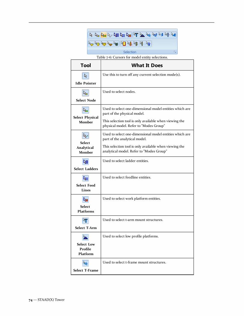
Tool What It Does
Idle Pointer
Use this to turn off any current selection mode(s).
Select Node
Used to select nodes.
Select PhysicalMember
Used to select one-dimensional model entities which arepart of the physical model.
This selection tool is only available when viewing thephysical model. Refer to "Modes Group"
SelectAnalyticalMember
Used to select one-dimensional model entities which arepart of the analytical model.
This selection tool is only available when viewing theanalytical model. Refer to "Modes Group"
Select Ladders
Used to select ladder entities.
Select FeedLines
Used to select feedline entities.
SelectPlatforms
Used to select work platform entities.
Select T-Arm
Used to select t-armmount structures.
Select LowProfilePlatform
Used to select low profile platforms.
Select T-Frame
Used to select t-frame mount structures.
Table 7-6: Cursors for model entity selections.
74— STAAD(X) Tower

Tool What It Does
Select SectorFrame
Used to select sector frame mount structures.
Select SideArm
Used to select side armmount structures.
Select MountPipe
Used to select mount pipes supporting appurtenances.
Select IceShield
Used to select an ice shield component.
Select DishWithoutRadome
Used to select a dish antenna without a radome cover.
Select DishWith Radome
Used to select a dish antenna with a radome cover.
Select DishWith Shroud
Used to select a shrouded dish antenna (HP dish).
Select GridDish
Used to select a grid dish.
Select Para-Reflector Dish
Used to select a para reflector dish.
Select PanelAntenna
Used to select a panel antenna.
Select YagiAntenna
Used to select a Yagi-Uda array (direction antenna).
User Manual — 75
Chapter 7 Command Reference: The Ribbon Toolbar
7.2 Model Tab

Tool What It Does
Select DipoleAntenna
Used to select a dipole antenna.
Select OmniAntenna
Used to select an omni antenna.
Select TMA
Used to select a tower mounted amplifier.
7.3 View tabContains tools for manipulating the View pane. You can toggle the views of members by class, change theview orientation, and switch between viewing the physical and analytical models.
Tool Description
PhysicalModel
Used to toggle the display of the physical model elements in theView pane (default view). The physical view mode is typically theenvironment in which you will construct tower models.
AnalyticalModel
Used to toggle the display of the physical model elements in theView pane. The analytical view mode is used for reviewing themathematical model which will be used by the STAAD(X) enginein analysis.
Note: Certain view features, such as member releases, mayonly be viewed in the Analytical Model display mode.
Monopole tower physical sections are sub-divided to maximumanalytical lengths based on selected code requirements (typically afive foot maximum analytical length).
Tools group Contains View From, Rotate, and Zoom tools used to control theView pane.
Selectiongroup
Contains a set of tools used for selecting physical model objects inthe View pane.
See "Selection Group" on page 73
Table 7-7: View tab tools
76— STAAD(X) Tower

Tool Description
Preferencesgroup
Used to toggle the view of members, nodes, and appurtenances bycategory.
StructuralDiagramscontrols
Used to control the graphic display details included in the Viewpane. By selecting the Apply Immediately option in the drop-down window, any selections made will be updated as soon as theyare selected. Otherwise, all changes will be applied once theApply button has been selected.
Take apicture
Opens the Take Picture dialog box, which is used to include modelviews or result diagrams in your report documents, or simplyexport images to external files.
View From tools
A set of tools used to control global orientation of the View pane by a set of predefined directions.
With the View Group on the Model Tab, there is a row of six tools which indicate highlighted faces of acube. Each of these changes the current Model View pane to align with either the positive or negativedirection on one of the three global axis.
A seventh tool highlights three faces of the cube. This changes the current Model View to an isometricview.
Note: View directions are absolute. Unlike Rotate View, these do not make incremental changes in thecurrent view but rather reset the current view to the selected direction.
Rotate View tools
Used to rotate the perspective in the View pane about all of the three global axis.
Tool What it DoesKeyboardCommand
Rotate Up
Rotates the active view counter-clockwise mannerabout the positive x-axis.
Ctrl + Up Arrow
Table 7-8: Rotate view tools
User Manual — 77
Chapter 7 Command Reference: The Ribbon Toolbar
7.3 View tab

Tool What it DoesKeyboardCommand
Rotate Down
Rotates the active view clockwise manner about thepositive x-axis.
Ctrl + Down Arrow
Rotate Left
Rotates the active view counter-clockwise mannerabout the positive y-axis.
Ctrl + Left Arrow
Rotate Right
Rotates the active view clockwise manner about thepositive y-axis
Ctrl + Right Arrow
Spin Left
Rotates the active view counter-clockwise about thepositive z-axis
Spin Right
Rotates the active view clockwise about the positive z-axis
Zoom tools
Used to control the zoom level within the View pane as well as pan about the view.
Tools What it Does
Zoom Window
Drag the mouse cursor to form a rectangle of the area youwant to fill the view pane with.
Zoom Out
Each click of this icon zooms the current view pane out by onestep.
Zoom Extents
Clicking this icon zooms the current view pane out to displaythe complete extents of the model.
Zoom In
Each click of this icon zooms the current view pane in by onestep.
Table 7-9: Zoom group tools
78— STAAD(X) Tower

Tools What it Does
Pan
Selecting this tool changes the mouse pointer to the Pan mode.Note the cursor changes to a hand. Click and hold the leftmouse button within the view pane to drag the model around.Note that the cursor changes reflect "grabbing" thescreen.You may release the mouse button and repeat to dragthe view as much as needed. Select thePantool again to exit Pan mode.
Preferences Group
Used to toggle the view of members, nodes, and appurtenances by category.
Members
You can toggle the graphical display of members within the View pane by type using thesebuttons. Clicking the Legs,Horizontals/Pull-offs, or Diagonals (Bracing) buttons will turnon the view of those members, respectively. You can combine them to show two or moremember types. Clicking the All Members button will reset the display. These commands donot affect the analytical model display mode.
Nodal
The Nodes and Supports buttons toggle the view each of these items, respectively.
When the Analytical Model view mode has been activated, you may also select theMemberReleases tool to view how member end specifications will be applied to the analytical model.Member releases are displayed as open circles near the end of the member. The memberToolTip will display additional information about the releases when the analytical memberselection tool is used.
Guys
If your model is a guyed tower, then the buttons to toggle the view of Guy Assemblies and
User Manual — 79
Chapter 7 Command Reference: The Ribbon Toolbar
7.3 View tab

Guy Cableswill be activated.
Faces
You can toggle the display of individual tower faces for self-supporting and guyed towerstructures.
Note: The tower legs on each side of the face will be displayed, along with all members inthe plane(s) of that tower face.
Appurtenances
These buttons allow you to toggle the display of tower appurtenances such as Antennas,Appurtenances, Platforms, Platforms, and Feedlines. For models where a given type ofappurtenance is not applicable, that toggle will be grayed out.
Structural diagram controls
Used to control the graphic display details included in the View pane. By selecting the Apply Immediatelyoption in the drop-down window, any selections made will be updated as soon as they are selected.Otherwise, all changes will be applied once the Apply button has been selected.
Color Tab
The color tab allows you to vary the color of displayed structural elements such as members, supports,and appurtenances.
80— STAAD(X) Tower

Change the Color of a Model Entity
1. Select the Structural Diagram pop-up dialog box from the View tab.
2. Select the Color tab in the dialog.
3. Select any color in the right column associated with the element you want to change. Thecolors can be selected either from the Custom tab, the Web (named colors) tab, or the Systemtab.
4. Select the Apply tool to update colors.
or
Select the Apply Immediately option to have all colors updated dynamically.
Use a Custom Color
1. When changing the color of a model entity as described above, select the Custom tab.
2. In any of the blank color spaces at the bottom of the dialog, right-click to open the Windowscolor picker dialog.
3. Use the color picker tool to select a hue and shade graphically.
or
Enter in numerical values for Hue, Saturation, and Lumosity.
or
Enter in numerical values for Red, Green, and Blue.
4. Select the Add to Custom Colors tool.
User Manual — 81
Chapter 7 Command Reference: The Ribbon Toolbar
7.3 View tab

5. Select the new color appears in the Custom colors grid.
6. Select the OK tool.
Label Tab
The Label tab allows you to toggle the display of element labels in the View pane.
Turn on Display Labels
1. Select the Structural Diagram pop-up dialog box from the View tab.
2. Select the Label tab in the dialog.
3. Select the box associated with any item label you want to be displayed.
4. Select the Apply tool to update labels.
or
Select the Apply Immediately option to have all colors updated dynamically.
82— STAAD(X) Tower
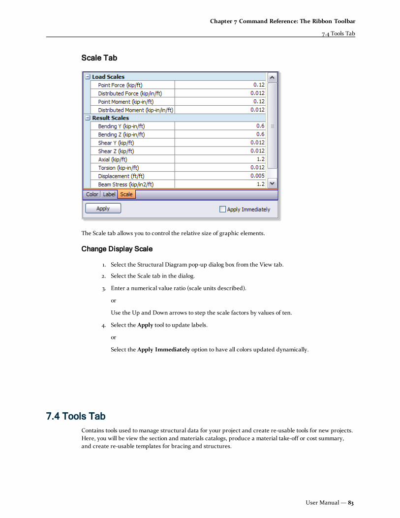
Scale Tab
The Scale tab allows you to control the relative size of graphic elements.
Change Display Scale
1. Select the Structural Diagram pop-up dialog box from the View tab.
2. Select the Scale tab in the dialog.
3. Enter a numerical value ratio (scale units described).
or
Use the Up and Down arrows to step the scale factors by values of ten.
4. Select the Apply tool to update labels.
or
Select the Apply Immediately option to have all colors updated dynamically.
7.4 Tools TabContains tools used to manage structural data for your project and create re-usable tools for new projects.Here, you will be view the section and materials catalogs, produce a material take-off or cost summary,and create re-usable templates for bracing and structures.
User Manual — 83
Chapter 7 Command Reference: The Ribbon Toolbar
7.4 Tools Tab

Tool Description
Split PhysicalLeg Members
Opens the Split Tower Member Leg dialog box, which isused to define member breaks in tower leg members byparameter.
Add HipMember
Opens the Add Hip Bracing Member dialog box, which isused to add a connecting two points within a tower bay (e.g.,bracing two diagonals out of plane) by selecting two existingnodes.
StructurePropertyCatalog
Opens the Structure Property Catalog dialog box, whichis used to add profile sections and associated materials to thetower model.
Steel CableCatalog
Opens the Steel Cable Explorer dialog box, which is usedto review and add steel cable profiles to your guyed towermodel.
Face BracingWizard
Opens the Define Bracing Pattern dialog box, which isused to define a custom face bracing pattern to add to theLibrary.
Plan BracingWizard
Opens the Define Bracing Pattern dialog box, which isused to define a custom horizontal bracing pattern to add tothe Library.
Table 7-10: Tools tab
Split Tower Leg Members dialog box
Used to define member breaks in tower leg members by parameter.
84— STAAD(X) Tower

Opens when the Split Physical Leg Members tool is selected.
Dialog Controls
Elevations list
All split definitions added to the current tower model are listed here.
Panel End tab
Used to select the Panel ID which will define the tower leg breaks. The tower legs are brokenat the top of the selected panel.
Custom tab
Used to specify the Height above base at which tower legs are broken. This allows you todefine tower leg breaks at any point along the vertical height of the tower model.
Remove
Used to remove the selected split definition from the Elevations list.
Add
Used to add a Panel End or Custom split definition to the Elevations list.
Done
Closes the dialog box and updates the model with the split definitions included in theElevations list.
Add Hip Bracing Member dialog boxUsed to add a connecting two existing points within a tower bay (e.g., bracing two diagonals out of plane)for a lattice tower structure.
Opens when the Add Hip Member tool is selected from the Tools ribbon tab.
Figure 7-1: The Add Hip Bracing Member dialog box
User Manual — 85
Chapter 7 Command Reference: The Ribbon Toolbar
7.4 Tools Tab

Add/Remove Hip Member
Select the action you want to perform for a hip member using the dialog box. Thecorresponding controls become active for your selection.
Type of Member
Select a redundant member classification by which the member will be grouped.
Panel No.
Specify a tower panel in which the member is to be added or removed. The Start Node andEnd Node lists are updated to include only existing nodes within the selected panel number.
Note: Hip members cannot span across panels.
Start Node
(Add Hip Member only) Select the node number which connects the start of the physicalmember.
End Node
(Add Hip Member only) Select the node number which connects the end of the physicalmember.
Section Profile
Select one of the available cross section profiles in the model.
Hint: Additional section profiles can be added using the Structure Property Catalog tool.
Member No.
(Remove Hip Member only) Select the hip member number from a list of hip members in theselected panel. This is the member that is removed when OK is clicked.
OK
When Add Hip Member is selected, this creates a hip member joining the two specifiednodes with the specified parameters. The program will check to ensure that no duplicatemembers are created.
Cancel
Closes the dialog box without creating a hip member.
Structure Property Catalog dialog box
Delete this text and replace it with your own content.
Standard tab
Provides you with catalog-listed shapes to use for your tower model.
86— STAAD(X) Tower

Standard Sections search criteria:
l Material — Select the material to be used
l Category — Specify which category of the material used
User Manual — 87
Chapter 7 Command Reference: The Ribbon Toolbar
7.4 Tools Tab

l Country — Specify the country where the section catalog is produced
l Specification — Specify the catalog to be used
l Profile Type — Specify the shape class
Material panel of the Property Catalog dialog box
Using the Structure Property Catalog
The geometric and material properties are added using the Structure Property Catalog. This centraldatabase contains all material and cross section data. The Structure Property Catalog dialog box isdivided into tabbed sections for rolled and prismatic sections. Either tab allows you to search databasesof cross-sectional shapes and add profile and material combinations to the tower model.
A list of all cross section profiles will be displayed in theModel > Physical Model > Properties> Profiles section of the Tower Model Explorer pane. Refer to this help topic for additional information onmanaging profiles and materials that have been added to your model file.s
Launching the Structure Property Catalog
1. From the Tools ribbon tab, select the Structure Property Catalog tool.
or
From theModel > Physical Model > Properties > Profile entry on the Tower ModelExplorer, select Add Section from the pop-up menu.
2. The Structure Property Catalog dialog box launches.
Adding a catalog section to the tower model
88— STAAD(X) Tower

1. Using the Structure Property Catalog dialog, select the criteria you want to use.
2. Press the Search button.
3. Select a section in the search results box and click Add Profile so that it is added to the list ofincluded profiles in the tower model.
or
Select both a section in the search results box and a material from the lower panel. Click AddProfile + Material so that both the profile and material are added to the tower model.
Hint:When a profile is selected, you can press the F2 key to select a new section size from the shapelist. The section profile is updated and any members with the previous size assigned will also beupdated with the new profile selection.
Available catalog shapes
STAAD(X) Tower contains an extensive catalog of standard shapes.
Country/Region CatalogShapes ClassesAvailable
United States AISC 7th Ed.(ASD)
L
AISC 13th Ed.(Imperial)
L, PIPE, 2L, HSS-ROUND, andSchifflerized L
AISC 9th Ed.(Imperial)
L, Pipe, 2L, HSS-Round, andSchifflerized L
API 5L All Steel Pipe
API 5L AlphaPipe
Pipe
India IS 808: 1989Generic
EA, UA, and TUBE
Table 7-11: List of Standard, Hot-Rolled Steel Catalog Shapes in STAAD(X) Tower
Schifflerized Angle
A standard angle section whose legs form a 60° angle instead of a 90°. These sections aredesignated by the letter V. Only equal leg angles are available in this shape class, which is mostcommonly used in three-legged towers.
User Manual — 89
Chapter 7 Command Reference: The Ribbon Toolbar
7.4 Tools Tab

Adding a material to the tower model
Note: Typically, a material that will be associated with a particular profile to complete a sectionproperty will be assigned from the Section Explorer when adding a profile.
1. Select theModel > Physical Model > Properties > Materials entry on the Tower ModelExplorer.
2. Right-click to open the pop-up menu and select Add Material.
3. Select theMaterial, Country, and Specification values you want to use. You may also selecta customMaterial Color to graphically represent this material.
4. Click Search.
5. Select a material from the search results list.
6. Click Add Material.
Steel Cable Explorer dialog box
Used to review and add steel cable profiles to your guyed tower model.
Opens when the Steel Cable Catalog tool is selected from the Tools ribbon tab.
90— STAAD(X) Tower

Adding a cable profile to the tower model
Note: Cable definitions are added using the Steel Cable dialog box.
1. Select the Steel Cable Catalog tool on the Tools ribbon tab.
The Steel Cable Explorer dialog box opens.
2. Select the Material and Standard from which you want to select a cable size.
The panes of the dialog box update to reflect your choice.
3. Double-click the Cable size you want to add to the profile list in the Tower Model Explorer.
Hint: The details of a selected cable profile are displayed at the bottom of the dialog.
User Manual — 91
Chapter 7 Command Reference: The Ribbon Toolbar
7.4 Tools Tab

Define (Face) Bracing Pattern dialog boxUsed to add a custom face panel pattern for your tower structure. Though STAAD(X) Tower includes anextensive list of commonly used bracing patterns for tower structures, you may find it necessary to addyour own. Your custom bracing patterns will be available along side the catalog patterns when selectingpanel bracing. Custom bracing panels will listed in theModel > Physical Model > Objects > Librariesentry on the Tower Model Explorer pane. See "Libraries" on page 173
Once you have added a custom bracing pattern, it will be available for future tower models as well whenyou run a new model wizard or edit panels in an existing model.
Opens when
l The Face Bracing Wizard tool is selected, or
l Define Bracing is selected from the Physical Model > Objects > Libraries pop-up menu inthe Tower Model Explorer pane.
Dialog Controls
Template
Control Description
Prototype Bracing Pattern Select one of the included bracing pattern
Bracing Title Specify a description which is used to inbracing library lists to refer to the newpattern.
Table 7-12: Define Bracing Pattern controls
Add: Node
92— STAAD(X) Tower

Control Description
Intersection This command will add a new node at theintersections of twomembers. You will beasked to specify twomembers by clickingthem. If these twomember segments do notintersect, a node will be added at theirprojected intersection. If two parallelmembers are selected, no node will beadded.
Extrapolate
Intermediate For this option, you must also specify thefractional length along a member where youwould like a new node added. Then youmust select the start and end nodes of themember in the pattern diagram. If youselect User Defined, then enter a valuebetween zero (0) and unity (1) as a ratio ofthe member length.
Intermediate Ratio Active when the Intermediate option hasbeen selected. Select one of the pre-definedration of member length or specify a UserDefined ratio.
Add Node Click this button to add a new node to thebracing pattern.
Table 7-13: Define Bracing Pattern controls
Add: Member
Control Description
Diagonal
Redundant Diagonal
Redundant Sub Diagonal
Secondary Horizontal
Redundant SubHorizontal
Redundant Vertical
Add Member Click this button to add a new member tothe bracing pattern.
Table 7-14: Define Bracing Pattern controls
Update
Creates a bracing pattern definition with the specified Bracing Title.
User Manual — 93
Chapter 7 Command Reference: The Ribbon Toolbar
7.4 Tools Tab

Cancel
Closes the dialog box without saving any changes since the last type Update button wasclicked.
Add a Custom Face Bracing Pattern
1. From the Tools ribbon tab, select the Face Bracing Wizard tool.
or
SelectDefine Bracing… from the pop-up menu on the Libraries entry in the Tower ModelExplorer pane.
The Define Bracing Pattern (face) dialog box opens.
2. Select a prototype bracing pattern from the predefined types (optional) if one is similar to thecustom pattern.
3. Enter an appropriate name in the Bracing Title field.
4. For each node or member you want to add, refer to the instructions below regarding Addinga Node or Adding a Member. Repeat to add as many new nodes or members as necessary.
5. Click the Update button to add the new bracing pattern (or click the Cancel button todiscard the new pattern).
Adding a Node
1. Select one of the following methods to add a node to the template:
2. Select the Add Node tool.
3. Depending on the method of addition selected, follow the instructions which appear in thebottom status bar.
Warning: An error message will be displayed if you attempt to create a duplicate node.
Adding a Member
1. Select the type of member you want to add to the template.
Note: Thought the member type does not affect the structural analysis directly, it willaffect how the structure is parametrically created and edited.
2. Select the Add Member tool.
3. Select the first and second nodes, respectively, to form the start and end of the additionalmember in the template.
94— STAAD(X) Tower

Warning: An error message will be displayed if you attempt to add a duplicate member or a zero-length member (e.g., start node and end node the same).
Deleting a Node or Member
1. Right click on the node or member you want to remove.
2. SelectDelete from the pop-up menu.
3. The item(s) selected for deletion will be highlighted and a confirmation dialog box will openasking to confirm their deletion.
4. Click Yes to proceed with the deletion.
Note: Removing nodes or members with dependant elements will require the deletion of dependants.These will be displayed when the confirmation dialog box opens.
Define (Plan) Bracing Pattern dialog boxUsed to define a custom horizontal bracing pattern to add to the Library.
Custom bracing horizontal plans will listed in theModel > Physical Model > Objects > Libraries entryon the Tower Model Explorer pane. See "Libraries" on page 173
Once you have added a custom bracing pattern, it will be available for future tower models as well whenyou run a new model wizard or edit panels in an existing model.
Dialog Controls
Template
User Manual — 95
Chapter 7 Command Reference: The Ribbon Toolbar
7.4 Tools Tab

Control Description
Tower Type Select the tower leg profile: Triangular orSquare
Prototype Bracing Pattern Select one of the included bracing pattern
Bracing Title Specify a description which is used to inbracing library lists to refer to the newpattern.
Table 7-15: Define Bracing Pattern controls
Add: Node
Control Description
Intersection This command will add a new node at theintersections of twomembers. You will beasked to specify twomembers by clickingthem. If these twomember segments do notintersect, a node will be added at theirprojected intersection. If two parallelmembers are selected, no node will beadded.
Extrapolate
Intermediate For this option, you must also specify thefractional length along a member whereyou would like a new node added. Then youmust select the start and end nodes of themember in the pattern diagram. If youselect User Defined, then enter a valuebetween zero (0) and unity (1) as a ratio ofthe member length.
Intermediate Ratio Active when the Intermediate option hasbeen selected. Select one of the pre-definedration of member length or specify a UserDefined ratio.
Add Node Click this button to add a new node to thebracing pattern.
Table 7-16: Define Bracing Pattern controls
Add: Member
Control Description
Horizontal Defines the physical member category formembers as Horizontal.
Table 7-17: Define Bracing Pattern controls
96— STAAD(X) Tower

Control Description
Add Member Click this button to add a new member tothe bracing pattern.
Update
Creates a bracing pattern definition with the specified Bracing Title.
Cancel
Closes the dialog box without saving any changes since the last type Update button wasclicked.
Add a Custom Plan Bracing Pattern
1. From the Tools ribbon tab, select the Plan Bracing Wizard tool.
The Define Bracing Pattern (plan) dialog box opens.
2. Select the Tower Type as either Triangular or Square.
3. Select a prototype bracing pattern from the predefined types (optional) if one is similar to thecustom pattern.
4. Enter an appropriate name in the Bracing Title field.
5. For each node or member you want to add, refer to the instructions below regarding Adding aNode or Adding a Member. Repeat to add as many new nodes or members as necessary.
6. Click the Update button to add the new bracing pattern (or click the Cancel button to discardthe new pattern).
Adding a Node
1. Select one of the following methods to add a node to the template:
2. Select the Add Node tool.
3. Depending on the method of addition selected, follow the instructions which appear in theHint field below the bracing diagram.
Warning: An error message will be displayed if you attempt to create a duplicate node.
Adding a Member
1. Select the Add Member tool.
2. Select the first and second nodes, respectively, to form the start and end of the additionalmember in the template.
User Manual — 97
Chapter 7 Command Reference: The Ribbon Toolbar
7.4 Tools Tab

Warning: An error message will be displayed if you attempt to add a duplicate member or a zero-length member (e.g., start node and end node the same).
Deleting a Node or Member
1. Right click on the node or member you want to remove.
Hint: Be cautious when clicking to ensure you are selecting the correct node or member.
2. SelectDelete from the pop-up menu.
3. The item(s) selected for deletion will be highlighted and a confirmation dialog box will openasking to confirm their deletion.
4. Click Yes to proceed with the deletion.
Note: Removing nodes or members with dependant elements will require the deletion of dependants.These will be displayed when the confirmation dialog box opens.
7.5 Components tabContains tools used to add tower components to your tower structure model.
Tool Description
T-Arm
Used to add a T-Arm support to the tower model.
Low ProfilePlatform
Used to add a Low Profile Platformmount to the towermodel.
T-Frame
Used to add a T-Frame mount to the tower model.
Table 7-18: Tools tab Discrete Appurtenance (Mounts) group
98— STAAD(X) Tower

Tool Description
Sector Frame
Used to add a Sector Frame mount to the tower model.
Side Arm
Used to add a Side Armmount to the tower model.
Pipe/Dish Mount
Used to add a Pipe mount to the tower model.
Ice Shield
Used to add a single Ice Shield to the tower model.
Tool Description
Guy Wires
Opens the Steel Cable dialog box, which is used to addcustom steel cable profiles to the program's database.
Coax Cables
Opens the Feed Line Shapes: Coaxial Cables dialog box,which is used to add custom coax data to the program for re-use.
WorkPlatform
Used to add a work platform to a latticed tower model. Workplatforms can square (four-sided towers only), triangular(three-sided towers only), or circular.
Table 7-19: Tools tab Discrete Appurtenance (Misc) group
User Manual — 99
Chapter 7 Command Reference: The Ribbon Toolbar
7.5 Components tab

Tool Description
Feed Line
Used to add a Feed Line definition to the Tower Model Explorerpane.
Ladder
Used to add a Ladder definition to the Tower Model Explorer pane.
Table 7-20: Tools tab Linear Appurtenances group
Note: The discrete (antennas, dishes, and mounts) and linear appurtenance (feed-lines inside andoutside) loading, except platform loads, cannot be considered for the analysis and design of monopoletowers.
Note: T-arms, T-frames, stand-offs, side arms, ice shields, and pipe mounts cannot be used in theanalysis and design.
Work Platform toolUsed to add tower platforms to your latticed tower model. Platforms are defined and added to thestructure through parameters in the Platform Properties. The program supports both square and roundplatforms shapes as well as full platforms or walkways.
Note: Discrete (antennas, dishes and Omni’s) appurtenances cannot be added to the faces of all thedifferent types of platforms.
Feedlines toolUsed to add a Feed Line definition to the model for self weight, wind, and ice load effects. Feed Lines aredefined and added to the structure through parameters in the Feed Line Properties.
Warning: This feature is considered a beta in V8i (SELECTseries 3) and is only applicable to 3 leggedtowers designed per TIA-222-F wind loads. A single set of feed-lines along a face can be consideredduring EIA/TIA-222-F design and analysis (Beta Feature) for 3-legged, self-supported tower only. Banjobrackets and t-brackets cannot be added for feed-lines.
Feedlines, also known as coax cables, are conduits for carrying electrical signals to the various antennas,dishes, etc. located on the tower. Feedlines are external components in case of self-supporting and guyed
100— STAAD(X) Tower

towers, and can be internal in case of monopoles. Custom coax data can be added to the program usingthe Feed Line Shapes: Coaxial Cables dialog box.
Ladder toolUsed to add a Ladder definition to the Tower Model Explorer pane. Ladders can be added to designatetheir associated dead and lateral loads
Note: Elements of the ladder are not designed by STAAD(X) Tower.
7.6 Results TabContains tools used to visualize results from the analysis on the model in the view pane. Here, you will beable to review member forces, member stresses, global reactions, and design results.
View Results Commands
The following commands are used to graphically display force, displacement, or stress results on thephysical model. The results are shown to scale (for scale settings, See "Scale Tab" on page 83) inwireframe, superimposed onto the current model view (Refer to "Modes Group" for model view settings).
The current load case may be selected by using the drop-down list in the Results group. This list includesall Primary Load Cases and Load Combinations included prior to running the most recent analysis.
Icon Description
Axial Force
The force along the local x-axis of the member.
Table 7-21: View Results commands
User Manual — 101
Chapter 7 Command Reference: The Ribbon Toolbar
7.6 Results Tab

Icon Description
Shear Y Force
The force along the local y-axis of the member.
Shear Z Force
The force along the local z-axis of the member.
Torsion
The twisting moment about the local x-axis of themember.
Bending Moment Y
The bending moment about the local y-axis of themember (generally weak-axis bending).
Bending Moment Z
The bending moment about the local z-axis of themember (generally strong axis bending).
Displacement
The deformed shape of the structure will bedisplayed.
Beam Stress
The combined stress along the local y-axis will bedisplayed for both above and below the neutral axisof the member.
Sup. Reaction Global support reactions values will be displayedalong each support. These will be listed in order offorce (X, Y, and Z) and moment (MX, MY, and MZ).
Show Results Group
This group provides you with tools to display all of the analysis results for a given load case. Select a loadcase from the menu of analyzed cases, then toggle on either force or stress results.
Tool What it does
ShowResultsBox
Used to open the Physical Member results dialog, which is used todisplay internal forces and displacements.
Table 7-22: Design Results group tools
102— STAAD(X) Tower

Tool What it does
ShowMemberStress
Used to display member section stresses at any point along thephysical member length.
ShowForceGraph
Used to open the Member Force Graph in the Output pane, which isused to display member forces plotted against the member length
LoadSelectionmenu
Used to select which load case for displaying results. This list isdynamically updated with all Primary Load Cases included in themost recent successful analysis.
See "Member Analysis Results" on page 59 for help using these tools.
Design Results tools
Used to display the design results once a successful code check has been performed.
Tool What it does
ShowAllResults
Used to review the code check status of members graphically and bythe Design Results Table.
Any members which have failed a code check will be displayed as redin the View pane and their Status will be set to Fail in the DesignResults Table.
ShowSelectiveResults
Used to review a more detailed set of results for a specific member.
The physical member properties and design parameters are displayedalong with the code check status. Also, the critical code checkinformation is presented along with each code check performed onthe selected member. Any code checks that exceed their allowablevalue will be highlighted for you.
Table 7-23: Design Results group tools
7.7 Report tabContains a number of features for formatting, viewing, and distributing your compiled reports. Once youload the Report tab, the Tower Model Explorer is replaced with two different side windows: the ReportDocument Map and the Selected Items List. These tools, along with the tools found along the ribbon bar,are used to add elements into your report, customize the format, and produce reports for external use.
User Manual — 103
Chapter 7 Command Reference: The Ribbon Toolbar
7.7 Report tab

Template Group
These commands allow you to create, modify, save, and load report templates.
Icon What it does
Load
Launches the Open Template dialog box. Here you will finda list of all saved template formats.
Prepare
Launches the Template Global Settings dialog box. Hereyou will find options for formatting aspects of reporttemplates.
Restore
This removes any changes made to a template since it wasloaded.
Clear
This deletes all template settings currently in use.
Save
Launches the Save Template dialog box so you may savethe current template settings for reuse.
Table 7-24: Report Template commands
Open Template Dialog
Template Name—A drop-down menu provides a list of all previously saved Templates.
Get Selected Entity List— Select this option to include any report objects which are in the includedtemplate's Selected Entity list.
104— STAAD(X) Tower

Get Each Object Customized Information— If the Get Selected Entity List option has been selected, thisoption may be selected to import any report object customizations which have been added to the selectedtemplate.
Template Global Settings
Save Template Dialog
Template Name— Enter a unique, alphanumeric name for the report template you want to save. Thecurrent report settings and options will be exported to this template name.
Note: If you enter the name of an existing template file, you will be prompted if you want to overwritethe existing file. This cannot be undone.
Save Selected Entity List— Select this option to include any report objects which are in the currentreport's Selected Entity list.
Save Each Object Customized Information— If the Save Selected Entity List option has been selected,this option may be selected to export any report object customizations which have been added to thecurrent report.
Set this Template as Default — Select this option to make the settings of this template the default whenthe Reports tab is opened.
Print Group
Commands for printing a hard copy of your report from STAAD(X) Tower.
User Manual — 105
Chapter 7 Command Reference: The Ribbon Toolbar
7.7 Report tab

Icon What it DoesKeyboardShortcut
Opens a Windows print dialog box toselect a printer and modify printerpreferences.
Ctrl + P
Quick Print
Sends the report directly to your defaultWindows printer.
Options
Inactive.
Table 7-25: Report Printing commands
Page Setup Group
Control the printed page size and layout of your report.
Icon What it Does
Header/Footer
Set the options for the header and footer of the reportdocument.
Scale
Opens the Scale Settings panel to set your report scale.
Margins
Opens theMargins gallery where you can select predefinedoptions or set custommargins.
Orientation
Opens the page Orientation gallery.
Size
Opens the Page Size gallery.
Table 7-26: Report page setup commands
106— STAAD(X) Tower

Scale Settings
Allows you to specify how the document should be scaled on a printed page.
Adjust to:— Set the scale based on the percentage to full size.
Fit to— Scale the report output based on page width.
Margins
The Margins tool opens the margins gallery, where allows you may select from a list of preset margin sizesor set CustomMargins.
Set Custom Margins
1. On the Reports ribbon tab, Click the Margins tool.
2. Select CustomMargins … at the bottom of the gallery list. The Page Setup dialog box opens.
User Manual — 107
Chapter 7 Command Reference: The Ribbon Toolbar
7.7 Report tab

3. Specify the Margins (in inches) in the Margins panel.
4. ClickOK.
Orientation
The Orientation tool opens the orientation gallery, where you can set the report page orientation toeither Portrait or Landscape.
Size
The Size tool opens the Page Size gallery, where you can select from a variety of common paper sizes foryour report output.
108— STAAD(X) Tower

Navigation Group
Here, you will find controls to navigate through your on-screen report.
Icon What it DoesKeyboardShortcut
Find
Opens the Find dialog boxwhich isused to search for specific text stringswithin your generated report.
First Page
Jumps the current report view to thefirst page.
Ctrl + Home
Previous Page
Steps the current report viewbackward one page.
Ctrl + Page Up
Next Page
Steps the current report view forwardone page.
Ctrl + PageDown
Last Page
Jumps the current report view to thelast page.
Ctrl + End
Table 7-27: Report screen navigation commands
User Manual — 109
Chapter 7 Command Reference: The Ribbon Toolbar
7.7 Report tab

Find dialog box
Used to search for specific text strings within your generated report.
Opens when you select the Find tool on the Report ribbon tab Navigation group.
Dialog Controls
Find what:
Specify a text string for which to search. Previously used text strings are available in the drop-down box by clicking the arrow.
Search Options
Select any combination of options to narrow your search:
l Match case— The search is case insensitive by default. This restricts the search touse on the letter case you enter.
l Match whole word— The search will return partial word matches by default. Thisoption restricts to only complete word matches (strings between whitespace andpunctuation).
l Search up— The search starts at the current point in the document and workstowards the end. This option reverses the search to move from the current pointtowards the beginning.
Find Next
Click this button to begin/continue the search
Close
This closes the Find dialog.
Zoom Group
A series of controls for setting the display of your current Report View.
110— STAAD(X) Tower
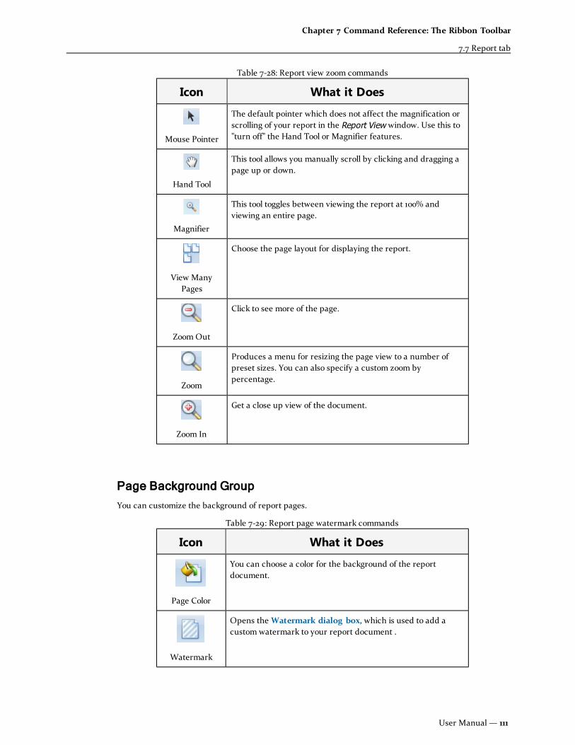
Icon What it Does
Mouse Pointer
The default pointer which does not affect the magnification orscrolling of your report in the Report View window. Use this to"turn off" the Hand Tool or Magnifier features.
Hand Tool
This tool allows you manually scroll by clicking and dragging apage up or down.
Magnifier
This tool toggles between viewing the report at 100% andviewing an entire page.
View ManyPages
Choose the page layout for displaying the report.
ZoomOut
Click to see more of the page.
Zoom
Produces a menu for resizing the page view to a number ofpreset sizes. You can also specify a custom zoom bypercentage.
Zoom In
Get a close up view of the document.
Table 7-28: Report view zoom commands
Page Background Group
You can customize the background of report pages.
Icon What it Does
Page Color
You can choose a color for the background of the reportdocument.
Watermark
Opens theWatermark dialog box, which is used to add acustom watermark to your report document .
Table 7-29: Report page watermark commands
User Manual — 111
Chapter 7 Command Reference: The Ribbon Toolbar
7.7 Report tab

Watermark dialog box
Used to add a custom watermark to your report document. Watermark images or text are often used toindicate that a document is to be treated specially (e.g., "Draft" or "For Internal Use Only").
Opens when theWatermark tool is selected from the Reports ribbon tab.
Text Watermark tab
Text
Enter a text string to use as a watermark. Common watermark text strings are available in adrop-down list by clicking the arrow.
112— STAAD(X) Tower

Direction
Specify the orientation of the text on the page using any of the preset options in the drop-downlist.
Font / Color / Size / Bold / Italic
Specify the look of the font using common typographical settings.
Transparency
Set the watermark transparency using the slider or text field. Zero represents an opaquewatermark; 255 will render the watermark entirely transparent.
Picture Watermark tab
Load Image …
Opens a Windows file open dialog box in order to select the image you want to use as awatermark (e.g.,a company or client logo).
Size mode
Specify how the watermark should be displayed if it is not the same width as the page:
l Clip— The left and right edges of the watermark will be clipped off if it is widerthan the page (at 100 dpi).
l Stretch— The watermark image will be stretched vertically and horizontally to fitthe entire page (this also means squashing if the image is larger than the page).This option does not keep the aspect ratio of the image in tact.
l Zoom— The watermark image will be resized to fill either the page width orheight, depending on which dimension ratio of the watermark is greater. Thisoption will keep the aspect ratio of the image in tact.
Horizontal / Vertical Alignment
Specify how the watermark image will be aligned on the page.
Transparency
User Manual — 113
Chapter 7 Command Reference: The Ribbon Toolbar
7.7 Report tab

Set the watermark transparency using the slider or text field. Zero represents an opaquewatermark; 255 will render the watermark entirely transparent.
Position and Range options
Position
Specify if the watermark is to appear in front of or behind (default) of the report content.
Page Range
The watermark may be added to All (default) pages or to a select range(s) of pages.
Clear All
Clears all text or image watermarks in the report.
OK
Accepts any changes made and closes the dialog.
Cancel
Closes the dialog box without saving any changes.
Export group
STAAD(X) Tower gives you the capability to save a prepared report in a variety of file formats for lateruse or distribution. The Export To… tools are used to save the file to a storage device (local hard drive,network drive, etc.). The E-Mail To… tools will open your default windows application and add the file asan e-mail attachment. Both will provide you with the same file options dialog before saving or attaching.
Tool What it does
PDF File
Opens the PDF Export Options dialog, which is used to savethe report as a portable document format (file extension.PDF) file. These files are commonly used to transport textand graphical data in a self-contained file. They require areader program, such as Adobe® Reader®.
HTML File
(Export to only) Opens the HTML Export Options dialog,which is used to save the report as a hypertext markuplanguage (file extension .HTM or .HTML) file. These files maycontain text, images, and formats in separate files(depending on the options selected). They are typically readby web browsers such as Microsoft Internet Explorer® andMozilla Firefox®.
Note: You cannot select HTML files for e-mailing. Use.MTH files instead for attaching a file which can be readby many web browsers.
Table 7-30: Export tools for saving and e-mail reports
114— STAAD(X) Tower

Tool What it does
MHT File
Opens the MHT Export Options dialog, which is used to savethe repot as a MIME HTML (.MHT) file. These files are self-contained html documents which can include rich datawhich can be read by Microsoft Internet Explorer® 5 orhigher.
RTF File
Opens the RTF Export Options dialog, which is used to savethe repot as a rich text file (file extension .RTF). Rich textfilescontains both text and images in a single file and alsopreserves much of the formatting from your report. Thesefiles can be read by a wide variety of word processingprograms, such as Microsoft Office Word® or SunOpenOffice®.
Excel File
Opens the XLS Export Options dialog, which is used to savethe report as a Microsoft Office Excel 2003 spreadsheet (fileextension .XLS). These files can contain images and textdata, as well as preserve the table structure. They also allowfor some richer formatting features for making your dataeasier to read. They are typically only readable byspreadsheet programs such as Microsoft Office Excel®, IBMLotus 1-2-3®, or Sun OpenOffice®.
CSV File
Opens the CSV Export Options dialog, which is used save thereport as a comma-separated values text file (file extension.CSV). These files are plain text with a specified contentdeliminater (typically a comma).
Note: No images will be included in this format.
Text File
Opens the Text Export Options dialog, which is used to savethe report as a plain text file. These files can be read by awide variety of programs and devices.
Note: No images will be included in this format.
Image File
Opens the Image Export Options dialog, which is used to savethe report to one of several image file types. Saving to animage file creates a raster image of the entire report output(though .WMF files can also include vector data). The data inthe image file is not directly editable, though image editorscan manipulate the file graphically. All information will behuman readable, though.
Note: Reports saved to image file formats will createsingle image files of the entire report, except for a.TIFF file which are multi-paged images.
User Manual — 115
Chapter 7 Command Reference: The Ribbon Toolbar
7.7 Report tab

Manage User Entities
User entries are report entities that you can use to add in external information or organize the report tobetter suit your needs. You can include additional images (diagrams), notes, or rich text documents aswell as group other report entities in the final report document.
Clicking the button (Manage User Entities) displays the Manger User Entities menu.
Add Diagrams, Notes, or Rich Text
You can import external content for inclusion in your STAAD(X) Tower reports. Such items are calledUser Entries. These may be images, plain text files, or rich text files.
1. Open the Manage User Entities menu.
2. Select Add Diagram to add an image file
or
Select Add Notes to add a text file as a note
or
Select Add Rich Text to add formatted text.
3. Provide a Item Label, Footer/Header text (for diagrams and notes, respectively), and specify afile for use in Item Link.
116— STAAD(X) Tower

File Formats
Diagrams — External image files to be used as report diagrams must be either JPEG (.jpg) or Bitmap(.bmp) types.
Notes — Documents to be used as notes must be plain text files with a .txt extension. These may becreated or edited with any plain text editor (such as Notepad).
Rich Text — External documents to be included must be in the Rich Text (.rtf) format. Most any wordprocessing software have the ability to save files in this format. No footer or headers are used when thesedocuments are added in the file. They will simply be inserted inline.
Report User Groups
You may create your own group definitions for how information in a report is organized.
To open the User Group management dialog:
1. Select Add/Update/Delete User Group from the Manage User Entities menu.
2. The User Group management dialog box opens.
Add a Report Group
1. Open the Add/Update/Delete dialog.
2. In the Report Group Header text box, enter a section title as you want it to appear in thereport.
Previous entries will appear in the list box below when the arrow is clicked.
3. Select all the Report Entities you want to have included in this Report User Group.
4. Click the (Add Group) button.
Note: Select the Immediately Refresh option before updating to have the report re-generated with thenew group.
> Update Existing Report Group
Report Group entities may be re-organized similarly to other report entities.
1. Open the Add/Update/Delete dialog.
2. Select the group want to change in the Report Group Header text box.
3. Select or unselect the Report Entities you want to have included in this Report User Group.
4. Click the (Update Group) button.
To have these changes reflected in the Selected Items List:
1. Click the (Update Selected Items List) button.
User Manual — 117
Chapter 7 Command Reference: The Ribbon Toolbar
7.7 Report tab
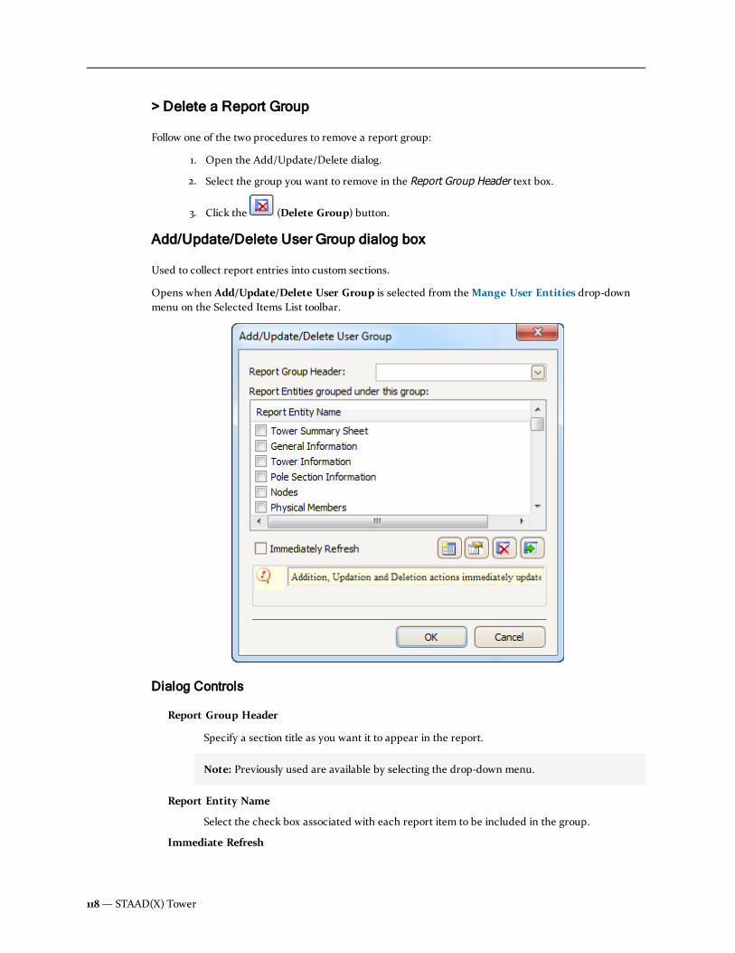
> Delete a Report Group
Follow one of the two procedures to remove a report group:
1. Open the Add/Update/Delete dialog.
2. Select the group you want to remove in the Report Group Header text box.
3. Click the (Delete Group) button.
Add/Update/Delete User Group dialog box
Used to collect report entries into custom sections.
Opens when Add/Update/Delete User Group is selected from theMange User Entities drop-downmenu on the Selected Items List toolbar.
Dialog Controls
Report Group Header
Specify a section title as you want it to appear in the report.
Note: Previously used are available by selecting the drop-down menu.
Report Entity Name
Select the check box associated with each report item to be included in the group.
Immediate Refresh
118— STAAD(X) Tower

Select this option to update the report group immediately. Otherwise, the report must beregenerated for the Group to update.
Add Group
Used add a report group with the specified header.
Update Group
Used to update the items included in the User Group. A message dialog box will openconfirming you want to update the Selected Items List.
Delete Group
Removes the selected User group from the Report.
Note: The report items which make up a group are still available to be included individuallyor as other groups.
Update Selected Items List
Updates the Selected Items List in the main window to include any changes made to thecurrent Report Group.
OK
Closes the dialog.
Cancel
Closes the dialog box without saving any changes.
User Manual — 119
Chapter 7 Command Reference: The Ribbon Toolbar
7.7 Report tab

120— STAAD(X) Tower
Chapter 7
7.7 Report tab

Chapter 8
Command Reference:Tower Model Explorer
This section contains details on using the Tower Model Explorer pane which contains elements of themodel in a familiar Windows tree outline view.
8.1 Project Information 121
8.2 Physical Model 122
8.3 Analysis 187
8.4 Design 191
8.1 Project InformationContains meta data about the model. When you select this item, the properties panel displays all theavailable fields for Project Information.
All tower models contain the Project Information section, though the contents of the Tower Informationand Tower Job Information fields are optional.
User Manual — 121

Tower Information
Project level information which describes the particular project. Tower Name and TowerDescription can be any string of characters.
Tower Job Information
Project level information which you supply for record keeping in your organization. JobName, Job Number, Client Name, Engineer Name, and Approved By can be any string ofcharacters.Worked On and Approved On are date formats. You can edit manually or usethe drop down calendar to select a date for these fields.
File Information
Relates to the computer file for the STAAD(X) Tower model. The File Name, File Path, and FileSize are displayed in non-editable fields.
Changing project information
1. Select theModel > Project Information branch of the Tower Model Explorer pane.
The job properties are displayed in the Properties pane.
2. Add, edit, or delete data in the Job Information fields as needed.
Hint: You can leave any of these fields blank or remove existing information by pressingthe Delete key.
Warning: You cannot edit File Information fields while the file is open. File name andlocation of a model may be changed in Windows Explorer provided that the model is notcurrently open in STAAD(X) Tower. However, doing so may result in unintendedconsequences for the recent files list.
8.2 Physical ModelContains all the information for physical model entities such as sections, materials, objects, and loads.When selected, this section also displays general information in the Properties pane about the towermodel.
Changing some physical model properties
Some of the physical model properties may be changed.
1. Select theModel > Physical Model > Tower Information branch of the Tower ModelExplorer pane.
The general information is displayed in the Properties pane.
122— STAAD(X) Tower
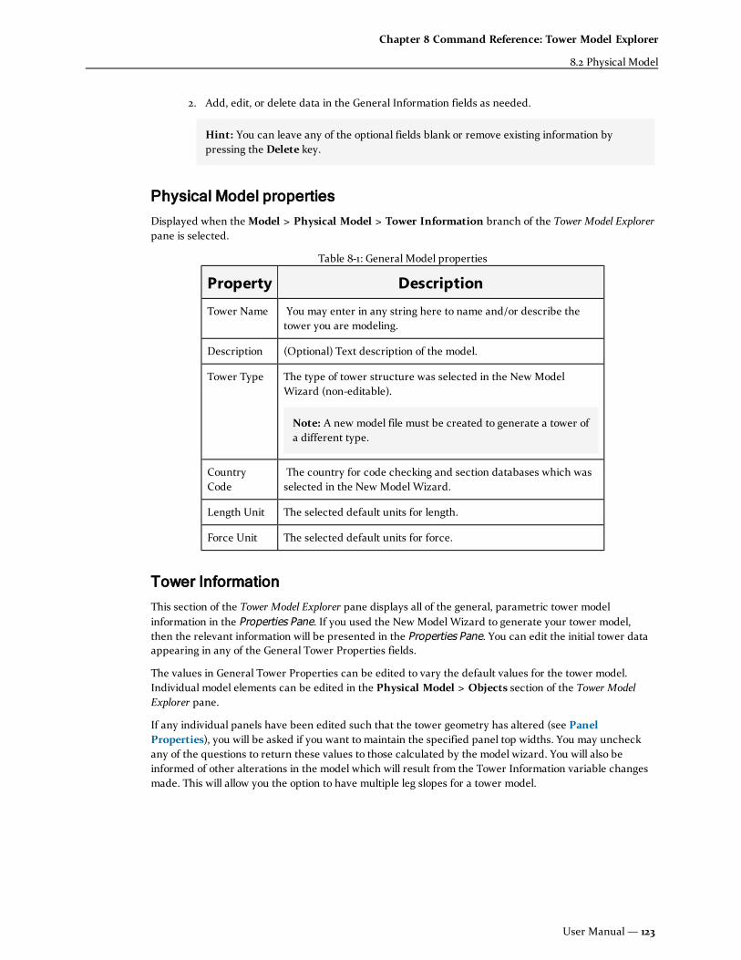
2. Add, edit, or delete data in the General Information fields as needed.
Hint: You can leave any of the optional fields blank or remove existing information bypressing the Delete key.
Physical Model properties
Displayed when theModel > Physical Model > Tower Information branch of the Tower Model Explorerpane is selected.
Property Description
Tower Name You may enter in any string here to name and/or describe thetower you are modeling.
Description (Optional) Text description of the model.
Tower Type The type of tower structure was selected in the New ModelWizard (non-editable).
Note: A new model file must be created to generate a tower ofa different type.
CountryCode
The country for code checking and section databases which wasselected in the New Model Wizard.
Length Unit The selected default units for length.
Force Unit The selected default units for force.
Table 8-1: General Model properties
Tower Information
This section of the Tower Model Explorer pane displays all of the general, parametric tower modelinformation in the Properties Pane. If you used the New Model Wizard to generate your tower model,then the relevant information will be presented in the Properties Pane. You can edit the initial tower dataappearing in any of the General Tower Properties fields.
The values in General Tower Properties can be edited to vary the default values for the tower model.Individual model elements can be edited in the Physical Model > Objects section of the Tower ModelExplorer pane.
If any individual panels have been edited such that the tower geometry has altered (see PanelProperties), you will be asked if you want to maintain the specified panel top widths. You may uncheckany of the questions to return these values to those calculated by the model wizard. You will also beinformed of other alterations in the model which will result from the Tower Information variable changesmade. This will allow you the option to have multiple leg slopes for a tower model.
User Manual — 123
Chapter 8 Command Reference: Tower Model Explorer
8.2 Physical Model

General Properties for Monopole towers
For towers with the monopole type listed under the Physical Model properties, the following GeneralTower Properties are presented in the Properties pane.
Property Description
Base TowerType
Defines how the cross section varies along the height of thetower structure: stepped or tapered (non-editable).
BaseElevation
The elevation of the tower above surrounding topography.Changing the Base Elevation value does not affect the geometryof the tower but will affect wind loading conditions.
Tower Height The height of the tower above the base elevation.
Bottom / TopDiameter
Specify the nominal diameter at the bottom and top of the tower,respectively.
Number ofSections
The tower is divided into the number of section divisionsspecified.
Number ofFacets
For tapered monopole sections, select the cross-section type bynumber of facets. For stepped monopole sections, the crosssection is always round.
Table 8-2: Monopole Tower: General Properties
General Properties for Self-Supporting towers
For towers with the self-supporting type listed under the Physical Model properties, the followingGeneral Tower Properties are presented in the Properties pane.
Property Description
Legs The number of tower legs in the model (non-editable).
Base Width The panel face width at the base of the tower.
Table 8-3: Self Supporting Tower: General Properties
124— STAAD(X) Tower

Property Description
Top Width The panel face width at the top of the tower.
Note: The slope of the tower legs (and, thusly, the slopepanel sides) is determined by Base Width, Top Width, andTower Height above base. However, you can edit the panelwidth of individual panels to alter the slope above and belowthat panel top.
BaseElevation
The elevation of the tower above surrounding topography.Changing the Base Elevation value does not affect the geometryof the tower but will affect wind loading conditions.
Tower Height The height of the tower above the base elevation.
Sections The number of tower sections along the height of the tower.
No. Of Bays The number of panel bays used in each section.
Note: If you have edited any of the Sections to have adifferent number of bays, the minimum number of bays persection is displayed in the Tower Information.
Panels The number of panel divisions along the height of the tower.
Note: You can also change the number of Panels in thetower model. The number of panels is counted up from thebase, such that higher values will add panels to the top of thestructure and lower values will remove the top panels. Thetop-most panel will maintain the Top Width value you havespecified. Therefore, the slope of the new panels will bedetermined by either the Base Width and Tower Height or bythe upper-most Top Panel Width and panel heights abovethat point (see Panel Properties for these variables).
Horizontals Select this box if horizontal members are present at the top ofeach panel.
Bracing Select the typical bracing pattern you want to apply for all panelfaces by default. Individual panels and panel faces may beedited individually to change from the default selected here.
General Properties for Guyed towers
For towers with the self-supporting type listed under the Physical Model properties, the following GeneralTower Properties are presented in the Properties pane.
User Manual — 125
Chapter 8 Command Reference: Tower Model Explorer
8.2 Physical Model

Property Description
Base TowerType
Indicates if the tower is square (four-legged) of triangular (three-legged) (non-editable).
BaseElevation
The elevation of the tower above surrounding topography.Changing the Base Elevation value does not affect the geometryof the tower but will affect wind loading conditions.
Tower Height The height of the tower above the base elevation.
Base FaceWidth
The panel face width at the base of the tower.
Note: If the Tapered at Base option is selected below, thiswidth will be used at the top of the highest tapered panel.That is, the panel width at the point of inflection between thetapered slope and the upper tower slope will be set equal tothis specified width.
Top FaceWidth
The panel face width at the top of the tower.
Number ofPanels
The number of panel divisions along the height of the tower.
Tapered atBase
Select this option to specify if tower model will be tapered at thebase level.
TaperedPanels
Specify the number of tapered panels at the base of the tower ifthe tapered option has been selected above.
Horizontals Select this option if horizontal members are present at the top ofeach panel.
PanelBracing
Select the typical bracing pattern you want to apply for all panelfaces by default. Individual panels and panel faces may be editedindividually to change from the default selected here.
Guy MountType
Select type of guy mount you want to use as a default for thismodel. Mounts may be changed individually in the model.Choose from:
l Corner Mount
l Face Mount
l Torque Arm Corner Mount
l Torque Arm Star Mount
Spread Specify the distance between the tip of the adjacent torque arms.
Torque ArmStyle
If you selected eitherTorque ArmCorner or Star Mount in the default type, you must also specifythe Torque Arm type.
Table 8-4: Guyed Tower: General Properties
126— STAAD(X) Tower

Properties
Contains the material and section information which has been added to the model file.
Profiles
Profiles describe the geometric properties assigned to a model entity. A list of all cross section profiles willbe displayed in theModel > Physical Model > Properties > Profiles section of the Tower ModelExplorerWindow. If you used a wizard to create your model, then any profiles you selected for themember classes are already listed there.
Note: Profiles must be added to the Tower Model Explorer before they may be used in members orengineering entities.
Assigning a profile
Once a profile has been added to the model, you need to assign it to the appropriate members.
1. Select the member(s) you want have a profile assigned to, either from the Tower ModelExplorer or the View pane.
2. Select the profile you want to use from theModel > Physical Model > Properties > Profilessection of the Tower Model Explorer.
3. From the pop-up menu of this profile, select Assign.
Changing a profile
Profiles themselves are non-editable. You may change the profile that you have added to the model file toa different profile within the same class.
1. When a profile is selected, press the F2 key
2. Select a new section size from the shape list.
The section profile is updated and any members with the previous size assigned will also beupdated with the new profile selection.
Additionally, if a custom shape is needed, you may create a user-defined profile with a catalog section as atemplate.
Materials
The list of material and grade combinations that have been added for use in the physical model aredisplayed in the Physical Model > Properties > Materials section of the Tower Model Explorer pane.
Note: Materials are non-editable and cannot be deleted from a tower model. To view materialproperties, you can select them in the Tower Model Navigator and the properties will be displayed inthe Properties pane.
User Manual — 127
Chapter 8 Command Reference: Tower Model Explorer
8.2 Physical Model

Assigning a material
1. Select the member(s) you want have a material assigned to, either from the Tower ModelExplorer or the View pane.
2. Select the material type you want to use from theModel > Physical Model > Properties >Materials section of the Tower Model Explorer.
3. From the pop-up menu of this material, select Assign.
Objects
Contains all of the tower model's physical objects.
Panels
A list of all panels along the height of the tower structure will be displayed in theModel > PhysicalModel > Objects > Panels section of the Tower Model Explorer pane. This allows you to manipulateindividual panels parametrically, instead of making changes or updates at the member or node level.
Panels are numbered starting with the first at the base and increasing along the tower height (positive Ydirection).
Note: Panels can only be added or removed by editing the Tower Information properties. The totalnumber of panels can be edited there, with panels counted up from the base.
Editing a panel
All panels will have the default properties as you specified in the New Tower Model wizard. A few simplecontrols allow you to edit the panel properties to generate irregular or specialized tower structures.
1. From theModel > Physical Model > Objects > Panels section of the Tower Model Explorer,select the panel which you want to edit.
All physical members within this panel will be shown rendered in the main View pane whileall other members in model will be shown in wireframe.
2. The parametric properties of the selected panel are displayed in the Properties pane.
Panel properties
By default, the tower structures created by the wizard have a constant taper and all panels have uniformheight (unless the Constant Slope option was deselected in the wizard, then the top panel will be madestraight).
128— STAAD(X) Tower

User Manual — 129
Chapter 8 Command Reference: Tower Model Explorer
8.2 Physical Model

Property Description
Panel ID This program assigned integer is used to identify the panel (non-editable).
Ht aboveBase
The height above the tower base to the top of the selected panel(non-editable)
Panel Height You may edit the Panel Height of each panel. To change theautomatically calculated panel height, specify the desired valueand press the Return key (or simply click outside of the field).
Note: The top panel height is non-editable. To extend the toppanel, the total tower height must be edited in the TowerInformation properties.
Top FaceWidth
Indicates the width at the panel top (non-editable).
Taper Panel Select this option to have the panel tapered with the tower taperfactor as determined by the wizard. Otherwise, this panel willhave the same top and bottom
Bottom FaceWidth
Indicates the width at the panel bottom (non-editable).
Apply to allfaces?
Select this option to use the bracing pattern selected for Face Afor all faces at this panel level.
Panel Faces The bracing pattern of each face of the selected panel may bevaried from the specified default pattern. Predefined or custompatterns from your Library are available in the drop-down list.Selecting the Top Horizontal box includes a horizontal brace atthe top of each face of the panel. Selecting the Apply to AllFaces? option will update all faces for the last selection made toany one. This keeps all of the bracing constant for all faces of theselected Panel.
Top Face:Bracing Type
Select a horizontal bracing pattern, if necessary, for thehorizontal tower section formed by the tops of each face at thispanel. Predefined or custom patterns from your Library areavailable in the drop-down list.
Table 8-5: Panel Properties
Displaying the panels table
For Self-Supporting Tower structures, you can display the panels table. This table can be used forreviewing and editing panels in one place.
1. Right click on theModel > Physical Model > Objects > Panels section of the Tower ModelExplorer.
130— STAAD(X) Tower

2. Select Show Self-Supported Panels Table from the pop-up menu.
The Panels table opens in the Output pane.
Sections
A list of all monopole sections along the height of the tower structure will be displayed in theModel> Physical Model > Objects > Sections section of the Tower Model Explorer pane. This allows you tomanipulate individual sections parametrically, instead of making changes or updates at the member ornode level.
Sections are numbered starting with the first at the top and increasing down the tower height (negative Ydirection).
Note: Each section consists of a single round or tapered member but sections are not the same as thecomponent member.
Note: Sections can only be added or removed by editing the general tower properties, found in TowerInformation. The total number of sections can be edited there, with panels counted up from the base.
Editing a section
All panels will have the default properties as you specified in the New Tower Model wizard. A few simplecontrols allow you to edit the panel properties to generate irregular or specialized tower structures.
1. From theModel > Physical Model > Objects > Sections section of the Tower ModelExplorer, select the section which you want to edit.
The parametric properties of the selected panel are displayed in the Properties pane
Section properties
Monopole towers do not have panels, but pole sections (which appear under the Panels section of theTower Model Explorer).
User Manual — 131
Chapter 8 Command Reference: Tower Model Explorer
8.2 Physical Model

Note: Only properties in black text on a white background are editable. Other properties in gray areinactive and are for information only.
Property Description
Section Program assigned identification number for the selectedmonopole section.
Elev. above Base Elevation at the top of the selected section above the basesupport of the monopole. Calculated by the Length ofselected sections and length of lower section(s).
Length The specified length of the selected section. Sectionsdefault to equal divisions along the specified tower height.
Note: The section length just above the tower basemay not be edited directly. It is calculated as the totaltower height above the base minus all other sectionlengths.
No. of Sides A round monopole simply displays Round for thisparameter.
Profile The physical member section specification is listed here.Any section which has been added to the model's Profilesmay be selected from the drop-down list. Thecorresponding Physical Member properties are updated.
Diameter The outer diameter of the selected Profile is displayedhere.
Wall Thickness The wall thickness of the selected Profile is displayedhere.
D/T Ratio The ratio of diameter to thickness is displayed here.
Table 8-6: Pole Section Information: Round
Property Description
Section Program assigned identification number for the selectedmonopole section.
Elev. above Base Elevation at the top of the selected section above the basesupport of the monopole.
Table 8-7: Pole Section Information: Tapered Monopole
132— STAAD(X) Tower

Property Description
Length
The specified length of the selected section. Sectionsdefault to equal divisions along the specified tower height.
Note: The section length just above the tower basemay not be edited directly. It is calculated as the totaltower height above the base minus all other sectionlengths.
Lap Splice Displays the actual length of the lap splice between theselected Pole Section and the section below it. TheRequired Lap Splice value is used by default but youspecify
No. of Sides The number of tapered tube facets for the selectedsection.
Top Depth/Dia. The ratio of diameter at the top of the section to thicknessis displayed here.
Bottom Depth/ Dia. The ratio of diameter at the bottom of the section tothickness is displayed here.
Thickness The wall thickness of the selected Profile is displayedhere.
GalvanizingThickness
The thickness of the galvanization coating is displayedhere.
Slope The slope of the taper along the
Required Lap Splice Displays the calculated length of the lap splice betweenthe selected Pole Section and the section below it.
Splice Check Displays the status of the lap splice code check.
Slope Check Displays the status of the slope code check.
Bend Radius As per TIA, the bend radius is equal to four times thethickness for tapered, n-sided polygon sections.
Displaying the sections table
1. Right click on theModel > Physical Model > Objects > Sections section of the Tower ModelExplorer.
2. Select Show Pole Sections Table from the pop-up menu.
The Pole Sections table opens in the Output pane.
User Manual — 133
Chapter 8 Command Reference: Tower Model Explorer
8.2 Physical Model

Nodes
All of the nodes in the model are listed in this branch of the Navigation Tree. Nodes are addedautomatically in the physical modeling process.
Node properties can be reviewed by one of the following:
1. Use the Select Node tool and highlight the node(s) you want to review in the View pane.
2. Expand the Physical Model > Objects > Nodes section of the Tower Model Explorer. From thepop-up menu, select Show Nodes. Select the node from the list you want to review.
The Node properties are displayed in the Properties Window.
Note: Nodal properties cannot be directly edited from the Properties Window. They are forinformation purposes only.
Members
TheModel > Physical Model > Objects > Members section of the Tower Model Explorer contains sub-sections for each of the physical object entities that may be present in your tower model. The sectionscan each be expanded for displaying and editing some entities.
The members are separated into tower structure element types such as legs, diagonals, horizontals, etc.
Note:When using the parametric modeling capabilities of STAAD(X) Tower, physical members areadded by changing model parameters such as panel bracing patterns.
134— STAAD(X) Tower

Display a list of all members in a classification
Initially, all of the individual physical member entries of any classification (i.e., legs, horizontals, diagonals,etc.) are not displayed. To display one such list:
1. Right-click on the corresponding section of theModel > Physical Model > Objects> Members > classification entry on the Tower Model Explorer pane. and select Show allDiagonal Members from the pop-up menu.
2. Click the to expand the list.
Hint: Diagonal members are listed from bottom to top of the structure and from face A to face C or D(for three- or four-sided tower structures, respectively).
3. Click on any diagonal member in either the Tower Model Explorer pane list or the View pane todisplay parameters in the Properties pane.
Refer to Edit a Member for information on property fields.
Editing a physical member
Before you beginTo see a list of all physical members of a particular classification, you must first display the list in theTower Model Explorer pane.
1. Either
select the physical member entry in theModel > Physical Model > Objects > Members >member type entry on the Tower Model Explorer pane
or
select the physical member graphically in the View pane using the Select Physical Membertool.
The properties for the selected physical member are displayed in the Properties pane forediting.
Member Releases
Each (linear) member in STAAD(X) Tower if restrained at both ends with six degrees of freedom, unless arelease is specified. In other words, all members are rigidly connected the nodes. You have the option torelease each of the degrees of freedom as well as specify a partial release by providing a spring constant.
Note: If the member end is a cantilever end or is supported, those conditions govern the degree offreedom at that location.
User Manual — 135
Chapter 8 Command Reference: Tower Model Explorer
8.2 Physical Model

Release Types
Specification Description
Full Fixed Degree of freedom is fully restrained at the node.
Full Release Degree of freedom has no restraint at the node.
Partial(Spring) Release
Degree of freedom is restrained to the node by the value ofthe spring constant specified.
Table 8-8: Release specifications
User-Specified End Releases
One or both ends of a member can be released. Members are assumed to be rigidly framed into joints inaccordance with the structural type specified. When this full rigidity is not applicable, you can setindividual force components at either end of the member to zero. By specifying release components,individual degrees of freedom are removed from the analysis.
Specifying a member end release
1. With the member selected, expand the Start Release and/or End Release section of theSpecification Information in the Properties pane.
2. Check the box to activate the release at the Start or End of the member.
3. For each of the end degrees of freedom you want to release, select Full Release from theassociated force/ moment menu.
136— STAAD(X) Tower

4. To specify a partial release, select Partial Release and provide a spring constant.
Note: Release components are given in the local coordinate system for each member.
Axial-only members
You may specify axial load-only members in STAAD(X) Tower. There are three different methods forspecifying an axial load member:
Specification Description
Truss Member A member which is only capable of carrying axial load,though in either tension or compression. Often, bracingmembers in a frame will use this specification. A Trussmember has only a single degree of freedom - axialdeformation. Any applied member loads are redistributedequally to each end as joint loads.
Compression OnlyMember
Compression -only members are truss members that arecapable of carrying compression forces only. Thus, they areautomatically inactivated for load cases that create tensionin them.
Tension OnlyMember
Tension-only members are truss members that are capableof carrying tensile forces only. Thus, they are automaticallyinactivated for load cases that create compression in them.
Table 8-9: Axial Only Member specifications
Specifying an axial-only member
Warning: A custom End Release should not be applied on a member which is declared Truss,Tension Only, or Compression Only.
1. Select the member which you want to specify as an axial-only member.
2. From the Properties pane, under Specification Information, set the options for which axial-only specification you want to use.
Member Offsets
Some members of a structure may not be concurrent with the incident joints thereby creating offsets.This offset distance is specified in terms of global or local coordinate system (i.e. X, Y and Z distances fromthe incident joint). Secondary forces induced, due to this offset connection, are taken into account in
User Manual — 137
Chapter 8 Command Reference: Tower Model Explorer
8.2 Physical Model
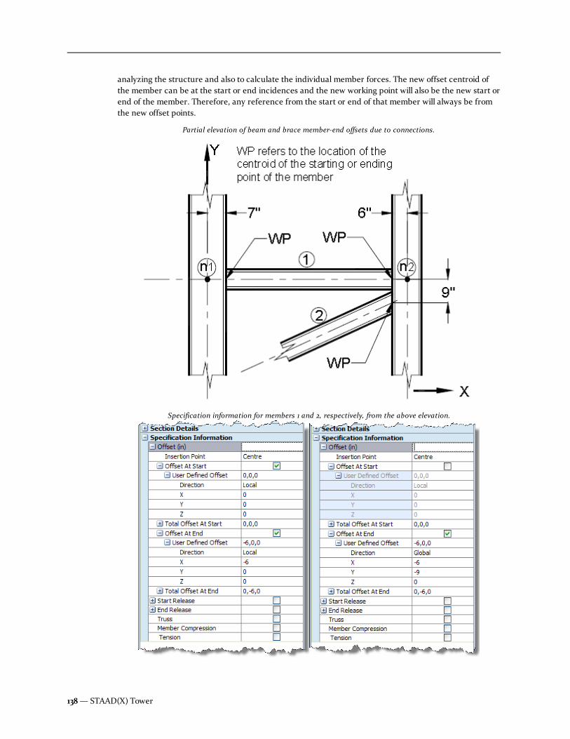
analyzing the structure and also to calculate the individual member forces. The new offset centroid ofthe member can be at the start or end incidences and the new working point will also be the new start orend of the member. Therefore, any reference from the start or end of that member will always be fromthe new offset points.
Partial elevation of beam and brace member-end offsets due to connections.
Specification information for members 1 and 2, respectively, from the above elevation.
138— STAAD(X) Tower

Insertion Point
STAAD(X) Tower provides you with the option of offsetting linear entities with regards to the local x-axisof that element. An imaginary line can be assumed that connects the two end points, or nodes, of amember. Under normal circumstances, this line passes through the centroid of the members profile (thisis the "center" insertion point). You can use the Insertion Point feature to specify pre-defined offsets,based on shape-specific geometric points.
When adding a new member, the insertion point may be set using the drop-down Add Member menufrom the Model ribbon tab.
Local Coordinate System
A local coordinate system is associated with each member. Each axis of the local orthogonal coordinatesystem is also based on the right hand rule. The following figure shows a beammember with start and end(e.g.,joints 'i' and 'j', respectively). The positive direction of the local x-axis is determined by joining start toend and projecting it in the same direction. The right hand rule may be applied to obtain the positivedirections of the local y and z axes. The local y and z-axes coincide with the axes of the two principalmoments of inertia. The local coordinate system is always rectangular.
Leg Members
Legs are physical members with a generally vertical (parallel to the global Y axis) orientation that form thecorners of self-supporting or guyed towers.
You can assign a section to all leg members when using the model wizard to generate your towerstructure. Each leg member will be a continuous member unless you have specified a maximum sectionlength which is exceeded or the structure geometry is altered such that a leg member has a discontinuity.
Note: The number and pattern of leg members are defined in the General Tower Properties. Thesecannot be directly added or deleted.
Hint: In theModel > Physical Model > Objects > Members > Legs entry on the Tower ModelExplorer pane, leg members are listed from bottom to top of the structure and from leg 1 to 3 or 4 (forthree- or four-sided tower structures, respectively). When legs are broken by discontinuities in thetower slope or by maximum length, multiple leg members
Horizontals
Horizontals are physical members oriented parallel to the global X-Z plane. These secondary members arein plane of the tower face and lay between two adjacent panel sections.
You can select to include horizontals automatically when using the model wizard to generate your towerstructure (self-supporting and guyed towers). You can also assign a section to all horizontal members atthis time.
Note: Horizontal members are added or removed by means of selecting the appropriate panel patternwhen selecting panels. Horizontal members are selected for each panel. You may also generate custompanels using the library editor.
User Manual — 139
Chapter 8 Command Reference: Tower Model Explorer
8.2 Physical Model

Hint: In theModel > Physical Model > Objects > Members > Horizontals entry on the TowerModel Explorer pane, horizontal members are listed from bottom to top of the structure and from faceA to face C or D (for three- or four-sided tower structures, respectively).
Diagonal Members
Diagonals are physical members oriented in the tower panel plane. These secondary members generallyform the intermediate bracing of a panel pattern.
You can assign a section to all diagonal members when using the model wizard to generate your towerstructure (self-supporting and guyed towers).
Note: Diagonal members are added or removed by means of selecting the appropriate panel patternwhen selecting panels. You may also generate custom panels using the library editor.
Hint: In theModel > Physical Model > Objects > Members > Diagonals entry on the Tower ModelExplorer pane, diagonal members are listed from bottom to top of the structure and from face A to faceC or D (for three- or four-sided tower structures, respectively).
Redundant Members
These are physical members oriented in the tower panel plane. These tertiary members form theintermediate bracing of a panel pattern along with the diagonal members. Multiple sections in theModel> Physical Model > Objects > Members > Redundant Members entry on the Tower Model Explorerpane are included to represent the various classifications of redundant members.
Redundant members inherit their section from diagonals when using the model wizard to generate yourtower structure (self-supporting and guyed towers).
Note: Redundant members are added or removed by means of selecting the appropriate panel patternwhen selecting panels. You may also generate custom panels using the library editor.
Hint: In theModel > Physical Model > Objects > Members > Redundant Members entry on theTower Model Explorer pane, redundant members are listed from bottom to top of the structure andfrom face A to face C or D (for three- or four-sided tower structures, respectively).
Guy Cables
Guy cables are physical members which provide stability to guyed structures.
The cable sections used for guys are selected when using the model wizard to generate your guyedtower structure.
Note: Guy cable members are added or removed by means of selecting the appropriate guy mountpatterns when specifying guy levels.
Hint: Guy cables are listed from bottom to top of the structure and from face A to face C or D (forthree- or four-sided tower structures, respectively).
140— STAAD(X) Tower

Guy Levels
Individual guy cables are connected to the main tower structure in a regular pattern which is specified byselecting a mount type. This pattern can repeat at different heights along the tower, each of which arereferred to as a guy level. Each guy level consists of several guy connections to the main tower structure.In the case of torque armmounts, additional members are used to transfer forces from the tower to theguys.
Adding a guy level
1. Right click on theModel > Physical Model > Objects > Guy Levels entry on the TowerModel Explorer pane and select Add Guy Level from the pop-up menu.
The Add Guy Level dialog box opens.
2. Enter the parameters for the new guide level.
3. ClickOK.
The new guy level and guy cables are added to the guyed tower model.
Editing a guy level
You can review a list of cable levels in the Tower Model Explorer pane:
Note: Editing guy mount properties will affect all guys at that level.
1. Select theModel > Physical Model > Objects > Guy Levels entry on the Tower ModelExplorer pane.
2. Click the to expand the list.
Hint: Guy cables are listed from bottom to top of the structure and from face A to face C or D (forthree- or four-sided tower structures, respectively).
User Manual — 141
Chapter 8 Command Reference: Tower Model Explorer
8.2 Physical Model

3. Click on any cable member in either the Tower Model Explorer pane list or the View pane todisplay parameters in the Properties pane.
Guy Level properties
Display the guy level properties by selecting a guy level in the Tower Model Explorer pane.
Property Description
Level An identification number assigned automatically. This is not directly editable.
Leg/Face The tower leg or tower face to which the guy mount is connected.
Mount heightabove Base
The elevation above tower base where the guy levels are attached to the main tower structure.
AnchorRadius
The straight-line distance (in the X-Z plane) from the center of the tower structure to the guyanchor.
AnchorElevation
The elevation above tower base where the guys at this level are anchored. Enter a negativevalue if the anchor elevation is below that of the base of the tower.
Note: Editing anchor radius or elevation will affect all guy anchors in the tower model.
Guy MountType
This describes the connection method which the guy cables are connected to the main towerstructure. The Spread value and Torque Arm Style values are required for corner or starmount types. See the following section on guy mount types.
Table 8-10: Guy Level properties
142— STAAD(X) Tower

Property Description
Spread (Corner or Star Mount styles only)
Torque ArmStyle
(Corner or Star Mount styles only)
Property Description
Standard Material used for the cable.
Designation Cable size used.
Apply at SameLevel
Select this option to have the cable properties applied to allguys at this guy level.
Table 8-11: Cable properties
Guy Mount types
There are four mount types available:
User Manual — 143
Chapter 8 Command Reference: Tower Model Explorer
8.2 Physical Model

MountType
Description Diagram
Corner Mount essentiallyprovides the wayto attach the guycable fromindividual legsand anchored atthe available baseelevation levelwhile respectingthe anchor radiusvalue for the guylevel. Thedirection ofanchoring mustmake an angle of45 degrees fromX direction incase of 4 leggedguy tower.
Four leg corner mount
Three leg corner mount
Table 8-12: Guy Mount types
144— STAAD(X) Tower

MountType
Description Diagram
Face guy cablemounting the twoguy cables fromindividual legsconstituting thevertical/inclinedboundary of theface of interestwill be pulledtogether to meetin a singularanchoring pointfound atconvenient baseelevation level.Each of these twoguy cables willsubtend sameangle with theX/Z direction asdecided by theface of interest.
Four leg face mount
Three leg face mount
User Manual — 145
Chapter 8 Command Reference: Tower Model Explorer
8.2 Physical Model

MountType
Description Diagram
Torque ArmCorner
two pulled offguy cables drivenout from twoadjacent face'storque armassembly getsunited at theconvenient baseanchor point. Incase of four (4)legged guy towerthe individualcables will makesame angle withthe imaginarydiagonals of thesquare tower.The imaginarydiagonals willmake 45 degreewith the principaltowerconstruction axis(X/Z).
Four leg torque arm corner mount
Three leg torque arm corner mount
146— STAAD(X) Tower

MountType
Description Diagram
Torque ArmStar
involves specifictorque armassemblies atuser specifiedguy level fromwhich the cableis pulled off andis anchored atthe convenientbase anchorpoint. Thedirection ofstressed cableswill always beparallel to theprincipal axis ofmain towerconstruction likeX/Z in case theguy tower hasfour (4)construction legs. Four leg torque arm star mount
Three leg torque arm star mount
Torque Arm styles
Both the corner mount and star mount types use torque arms to transfer forces into the guys. If either ofthese are selected, a torque arm style must also be specified. There are four styles available:
User Manual — 147
Chapter 8 Command Reference: Tower Model Explorer
8.2 Physical Model
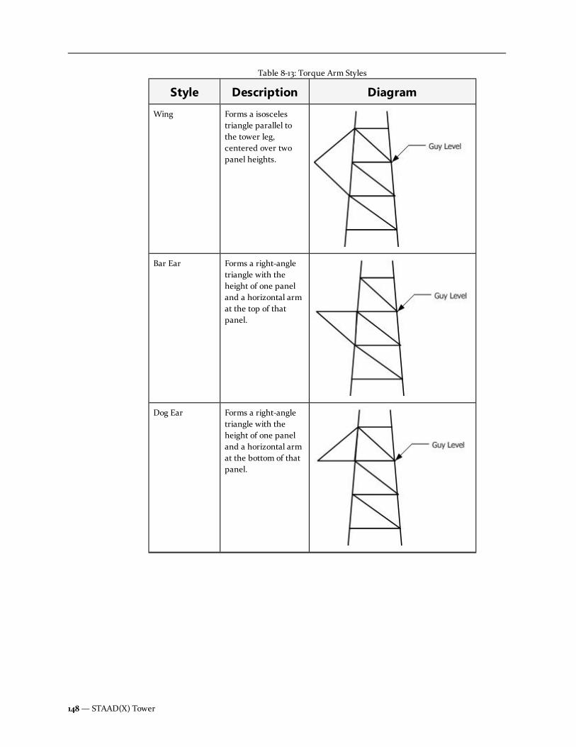
Style Description Diagram
Wing Forms a isoscelestriangle parallel tothe tower leg,centered over twopanel heights.
Bar Ear Forms a right-angletriangle with theheight of one paneland a horizontal armat the top of thatpanel.
Dog Ear Forms a right-angletriangle with theheight of one paneland a horizontal armat the bottom of thatpanel.
Table 8-13: Torque Arm Styles
148— STAAD(X) Tower

Style Description Diagram
Cantilever A single cantileveredmember is used atthe panel heightspecified.
Additionally, when a torque arm is used, the spread value must be specified. This is the distance betweenthe guy end points on two adjacent torque arms.
Components
You can add multiple components to the tower physical model. Components are considered for bothgravity and lateral loads. They can be either selected from vendor catalog lists included in the interface orcustom components may be generated parametrically.
Note: If you have opened a STAAD(X) Tower file created in a previous version of the program whichcontains Antennas or Appurtenances, these will be listed here as in previous versions of the program.These files may be analyzed and designed as in previous versions. If additional components must beadded, the new mount tools must be used.
Mounts
A list of all mounts which have been added to the structure is displayed in theModel > Physical Model> Objects > Components > Mounts section of the Tower Model Explorer pane.
Individual mount pipes and their attached appurtenances are includes as children of the associatedmount.
Mount properties
The Properties pane displays the mount properties when a mount is selected in theModel > PhysicalModel > Objects > Components > Mounts section of the Tower Model Explorer pane.
Parameter Description
Mount Number Integer assigned by the program to identify the mount. (non-editable)
Elevation Height above ground of the mount.
Table 8-14: Mount properties
User Manual — 149
Chapter 8 Command Reference: Tower Model Explorer
8.2 Physical Model

Parameter Description
Type of Mount Select the type of mount from the drop-down list. Not all mounttypes are available for all tower types.
No of mounttypes
ForT-ArmarmSide Armmount types, select the number of arms at this mount location.These will be
Appurtenance properties
The Properties pane displays the appurtenance properties when an antenna is selected in theModel> Physical Model > Objects > Components > Mounts > Mount # > … > Antenna # - type sectionof the Tower Model Explorer pane or using the antenna type selection tools in the View pane.
Parameter Description
Antenna Number Integer assigned by the program to identify theplatform. (non-editable)
Loading Classification SelectExisting,Reserved, orProposedfrom the drop-down list in order to classify themount.
Manufacturer Select a catalog manufacturer to automaticallypopulate the size and weight.
Model No. Select an antenna model number from the selectedManufacturercatalog.
Antenna Type Select the type of antenna:
l Dipole
l Dish
l Omni
l Panel
l Yagi
Refer to the antenna type properties below forsettings appropriate to the selected antenna type.
Table 8-15: Appurtenance properties
150— STAAD(X) Tower

Parameter Description
Length of Antenna Type the length of the antenna along the towerheight (global Y axis).
Azimuth Type the rotation of the antenna with respect to themount. Rotation is measured perpendicular to thelocal mount azimuth, clockwise.
Ka, Front/Side The shielding factor for appurtenances, as used inthe front (along global X direction) and side (alongglobal Z direction) wind. This value is applicable fordesign per the TIA-222-G code only.
Note: The Ka factor for other appurtenances isconservatively taken as 1 per Section 2.6.9.2 ofthe TIA-222-G code. This is the default value.
Horizontal Offset Location of the appurtenance from the face of thestructure/leg.
Lateral Offset Location of the pipe mount and attached antennasalong the width of the mount. This option can alsobe used when the azimuth is not zero.
Note: Based on the Azimuth, you can definethe lateral offset to locate the force pointapplication.
Vertical Offset Used to shift a particular mount pipe and antennaabove or below the elevation of the mount.
EPA or Area (CaAa) (EPA for EIA/TIA-222-G) The effective projectedarea (EPA) values for Front (wind along X)—(EPA)
N—and Side (wind along Z)—(EPA)
T—with
and without ice are calculated and displayed here.
(CaAa used for EIA/TIA-222-F) For discrete andlinear appurtenances, this value is C
aAa, where:
Ca= the force coefficient
determined by Section 2.3.7 in theTIA-222-F code
Aa= projected area of the
component, with or without ice forthe appropriate field.
Weight The weight of the platform with and without ice iscalculated and displayed here.
No of TMA For panel antennas, select the number… , up to six.
User Manual — 151
Chapter 8 Command Reference: Tower Model Explorer
8.2 Physical Model

Parameter Description
Width of Panel Antenna Type the height of the panel antenna.
Depth of Panel Antenna Type the width of the panel antenna.
Table 8-16: Panel Antenna properties
Parameter Description
Dipole Type Select the number of bays in the dipole antenna: 2, 4, 6, 8, or10.
Table 8-17: Dipole Antenna properties
Parameter Description
Dish AntennaDiameter
Outer diameter of the dish antenna.
Dish Type Select the dish type:
l Grid
l HP Dish
l Parabola without Radome
l Parabola with Radome
l Para Reflector
Dish AppurtenanceArea (No Ice / Ice)
The effective projected area without and with ice (both1/2 inch and 2 inch of ice are calculated).
Table 8-18: Dish Antenna properties
T-Arm properties
The Properties pane displays the t-arm properties when a t-arm is selected in theModel > PhysicalModel > Objects > Components > Mounts > Mount # > t-arm elev.-Leg section of the Tower ModelExplorer pane or using the Select T-Arm tool in the View pane.
Parameter Description
T- Arm Number Integer assigned by the program to identify the platform. (non-editable)
LoadingClassification
SelectExisting,Reserved, orProposedfrom the drop-down list in order to classify the mount.
Manufacturer n/a
Table 8-19: T-Arm properties
152— STAAD(X) Tower

Parameter Description
Model No. n/a
Orientation Select the tower leg from which the T-arm is supported.
Stand-OffDistance
Type the length of the support mount (i.e., the distance between thepanel face, tower leg, or pole and the cross arm).
Width of T-Arm Type the length of the armmember.
Add SupportArm
Set this option to include a support armmember for the T-Arm.
Support ArmElevation
Type an elevation of the support armmember.
HorizontalOffset
Location of the appurtenance from the face of the structure/leg.
Lateral Offset Location of the pipe mount and attached antennas along the width ofthe mount. This option can also be used when the azimuth is not zero.
Note: Based on the Azimuth, you can define the lateral offset tolocate the force point application.
Vertical Offset Used to shift a particular mount pipe and antenna above or below theelevation of the mount.
Ka, Front/Side The shielding factor for appurtenances, as used in the front (alongglobal X direction) and side (along global Z direction) wind. This valueis applicable for design per the TIA-222-G code only.
Note: The Ka factor for other appurtenances is conservativelytaken as 1 per Section 2.6.9.2 of the TIA-222-G code. This is thedefault value.
User Manual — 153
Chapter 8 Command Reference: Tower Model Explorer
8.2 Physical Model

Parameter Description
Azimuth forMount Rotation
Type the angle between a line normal to a plane tangent to the towerstructure and the support arm, measured clockwise. Refer to "A" inthe figure below.
Figure 8-1: Azimuths for t-arm mounts A) for mount rotation and B) for armrotation
Azimuth forArm Rotation
Type the angle between a line normal to the mount and the crossarm. Refer to "B" in the figure above.
EPA or Area(CaAa)
(EPA for EIA/TIA-222-G) The effective projected area (EPA) values forFront (wind along X)—(EPA)
N—and Side (wind along Z)—(EPA)
T—
with and without ice are calculated and displayed here.
(CaAa used for EIA/TIA-222-F) For discrete and linearappurtenances, this value is C
aAa, where:
Ca= the force coefficient determined by Section 2.3.7
in the TIA-222-F code
Aa= projected area of the component, with or without
ice for the appropriate field.
Weight The weight of the t-arm with and without ice is calculated anddisplayed here.
No. of MountPipes
Select the number of mount pipes arranged along the t-arm (up tosix). Mount pipes are arranged equally spaced along the arm, withone at each end (unless a single mount pipe is selected for a arm, inwhich case it is placed in the center of the arm).
154— STAAD(X) Tower
Low Profile Platform properties
The Properties pane displays the low profile platform properties when a low profile platform is selected intheModel > Physical Model > Objects > Components > Mounts > Mount # > Low ProfilePlatform # section of the Tower Model Explorer pane or using the Select Low Profile Platform tool inthe View pane.
Parameter Description
Low ProfilePlatformNumber
Integer assigned by the program to identify the platform. (non-editable)
LoadingClassification
SelectExisting,Reserved, orProposedfrom the drop-down list in order to classify the mount.
Manufacturer n/a
Model No. n/a
Shape Only triangular low profile platforms are supported.
Width ofPlatform
Type a width (face of triangle) for the platform.
Grating Set this option if the platform includes catwalk grating along theedges.
No. ofHandrails
Select the number of handrails along each edge, up to six.
Top-mostHandrailElevation
Type the elevation above ground of the top handrail. The No. ofHandrails selected (if any) are distributed between theplatform and this elevation.
Azimuth Type the angle measured parallel to the global X axis and FaceC of a the triangular platform.
Ka, Front/Side The shielding factor for appurtenances, as used in the front(along global X direction) and side (along global Z direction)wind. This value is applicable for design per the TIA-222-G codeonly.
Note: The Ka factor for other appurtenances isconservatively taken as 1 per Section 2.6.9.2 of the TIA-222-G code. This is the default value.
Table 8-20: Low Profile Platform properties
User Manual — 155
Chapter 8 Command Reference: Tower Model Explorer
8.2 Physical Model

Parameter Description
HorizontalOffset
Location of the appurtenance from the face of thestructure/leg.
Lateral Offset Location of the pipe mount and attached antennas along thewidth of the mount. This option can also be used when theazimuth is not zero.
Note: Based on the azimuth, you can define the lateraloffset to locate the force point application.
Vertical Offset Used to shift a particular mount pipe and antenna above orbelow the elevation of the mount.
No. of MountPipes: FaceA/B/C
Select the number of mount pipes arranged along the platformface (up to six). Mount pipes are arranged equally spaced alongthe face, with one at each end (unless a single mount pipe isselected for a face, in which case it is placed in the center ofthe face).
No. of MountPipes: LegA/B/C
Select if a mount pipe is included at the corner leg of theplatform.
EPA or Area(CaAa)
(EPA for EIA/TIA-222-G) The effective projected area(EPA) values for Front (wind along X)—(EPA)
N—and Side (wind
along Z)—(EPA)T—with and without ice are calculated and
displayed here.
(CaAa used for EIA/TIA-222-F) For discrete and linearappurtenances, this value is C
aAa, where:
Ca= the force coefficient determined by Section
2.3.7 in the TIA-222-F code
Aa= projected area of the component, with or
without ice for the appropriate field.
Note: Refer to Section 2.6.2.9.4 of the TIA-222-G code fordetermination of the EPA for low profile platforms.
Weight The weight of the platform with and without ice is calculatedand displayed here. You may type in override values ifnecessary.
T-Frame properties
The Properties pane displays the t-frame properties when a t-frame is selected in theModel > PhysicalModel > Objects > Components > Mounts > Mount # > T-Frame elev.-Leg section of the TowerModel Explorer pane or using the Select T-Frame tool in the View pane.
156— STAAD(X) Tower

Parameter Description
T- FrameNumber
Integer assigned by the program to identify the platform. (non-editable)
LoadingClassification
SelectExisting,Reserved, orProposedfrom the drop-down list in order to classify the mount.
Manufacturer n/a
Model No. n/a
Orientation Select the tower leg to which the T-Frame mount is connected.
Stand-OffDistance
Type the length of the support mount (i.e., the distance between thepanel face, tower leg, or pole and the cross arm).
Width of T-Arm Type the length of the armmember.
Tie Back Set this option to include…
No. of MountPipes
Select the number of mount pipes arranged along the t-frame (up tosix). Mount pipes are arranged equally spaced along the arm, withone at each end (unless a single mount pipe is selected for a arm, inwhich case it is placed in the center of the arm).
Ka, Front/Side The shielding factor for appurtenances, as used in the front (alongglobal X direction) and side (along global Z direction) wind. This valueis applicable for design per the TIA-222-G code only.
Note: The Ka factor for other appurtenances is conservativelytaken as 1 per Section 2.6.9.2 of the TIA-222-G code. This is thedefault value.
HorizontalOffset
Location of the appurtenance from the face of the structure/leg.
Lateral Offset Location of the pipe mount and attached antennas along the width ofthe mount. This option can also be used when the azimuth is not zero.
Note: Based on the Azimuth, you can define the lateral offset tolocate the force point application.
Vertical Offset Used to shift a particular mount pipe and antenna above or below theelevation of the mount.
Table 8-21: T-Frame properties
User Manual — 157
Chapter 8 Command Reference: Tower Model Explorer
8.2 Physical Model

Parameter Description
Azimuth forMount Rotation
Type the angle between a line normal to a plane tangent to the towerstructure and the support frame, measured clockwise. Refer to "A" inthe figure below.
Figure 8-2: Azimuths for t-frame mounts A) for mount rotation and B) forframe rotation
Azimuth forArm Rotation
Type the angle between a line normal to the mount and the crossarm. Refer to "B" in the figure above.
Area The effective projected area (EPA) values for Front (wind along X)—(EPA)
N—and Side (wind along Z)—(EPA)
T—with and without ice are
calculated and displayed here.
For discrete and linear appurtenances, this value is CaAa, where:
Ca= the force coefficient determined by Table 2-8 in
the TIA-222-G code
Aa= projected area of the component, with or without
ice for the appropriate field.
Weight The weight of the t-frame with and without ice is calculated anddisplayed here.
Sector Frame properties
The Properties pane displays the sector frame properties when a sector frame is selected in theModel> Physical Model > Objects > Components > Mounts > Mount # > Sector Frame elev.-Leg section
158— STAAD(X) Tower

of the Tower Model Explorer pane or using the Select Sector Frame tool in the View pane.
Parameter Description
Sector FrameNumber
Integer assigned by the program to identify the platform. (non-editable)
LoadingClassification
SelectExisting,Reserved, orProposedfrom the drop-down list in order to classify the mount.
Manufacturer n/a
Model No. n/a
Orientation Select the tower leg to which the T-Frame mount is connected.
Stand-OffDistance
Type the length of the support mount (i.e., the distance between thepanel face, tower leg, or pole and the cross arm).
Width Type the length of the armmember.
Tie Back Set this option to…
No. of MountPipes
Select the number of mount pipes arranged along the t-frame (up tosix). Mount pipes are arranged equally spaced along the arm, withone at each end (unless a single mount pipe is selected for a arm, inwhich case it is placed in the center of the arm).
Ka, Front/Side The shielding factor for appurtenances, as used in the front (alongglobal X direction) and side (along global Z direction) wind. This valueis applicable for design per the TIA-222-G code only.
Note: The Ka factor for other appurtenances is conservativelytaken as 1 per Section 2.6.9.2 of the TIA-222-G code. This is thedefault value.
HorizontalOffset
Location of the appurtenance from the face of the structure/leg.
Lateral Offset Location of the pipe mount and attached antennas along the width ofthe mount. This option can also be used when the azimuth is not zero.
Note: Based on the Azimuth, you can define the lateral offset tolocate the force point application.
Vertical Offset Used to shift a particular mount pipe and antenna above or below theelevation of the mount.
Table 8-22: T-Frame properties
User Manual — 159
Chapter 8 Command Reference: Tower Model Explorer
8.2 Physical Model
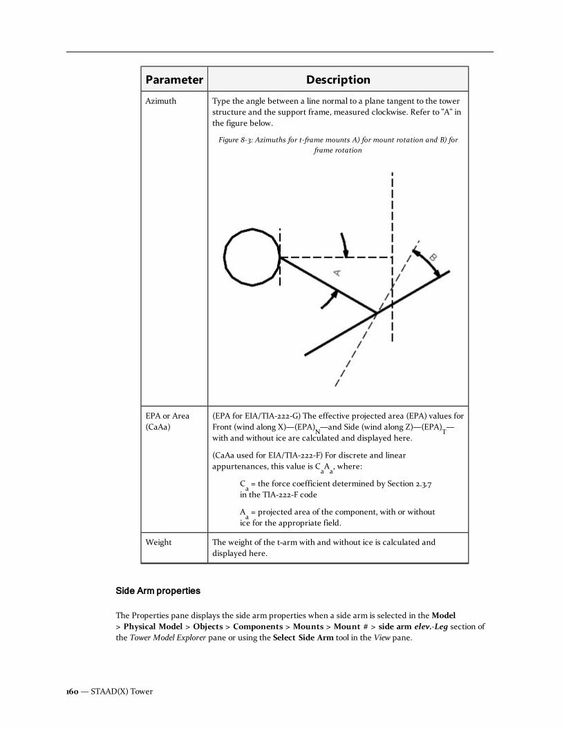
Parameter Description
Azimuth Type the angle between a line normal to a plane tangent to the towerstructure and the support frame, measured clockwise. Refer to "A" inthe figure below.
Figure 8-3: Azimuths for t-frame mounts A) for mount rotation and B) forframe rotation
EPA or Area(CaAa)
(EPA for EIA/TIA-222-G) The effective projected area (EPA) values forFront (wind along X)—(EPA)
N—and Side (wind along Z)—(EPA)
T—
with and without ice are calculated and displayed here.
(CaAa used for EIA/TIA-222-F) For discrete and linearappurtenances, this value is C
aAa, where:
Ca= the force coefficient determined by Section 2.3.7
in the TIA-222-F code
Aa= projected area of the component, with or without
ice for the appropriate field.
Weight The weight of the t-arm with and without ice is calculated anddisplayed here.
Side Arm properties
The Properties pane displays the side arm properties when a side arm is selected in theModel> Physical Model > Objects > Components > Mounts > Mount # > side arm elev.-Leg section ofthe Tower Model Explorer pane or using the Select Side Arm tool in the View pane.
160— STAAD(X) Tower

Parameter Description
Side ArmNumber
Integer assigned by the program to identify the side armmount. (non-editable)
LoadingClassification
SelectExisting,Reserved, orProposedfrom the drop-down list in order to classify the mount.
Manufacturer n/a
Model No. n/a
Orientation Select the tower leg from which the side armmount issupported.
Stand-OffDistance
Type the length of the support mount (i.e., the distancebetween the panel face, tower leg, or pole and the end of theside arm).
No. of MountPipes
Select the number of mount pipes arranged along the t-arm (upto six). Mount pipes are arranged equally spaced along the arm,with one at each end (unless a single mount pipe is selected fora arm, in which case it is placed in the center of the arm).
Ka, Front/Side The shielding factor for appurtenances, as used in the front(along global X direction) and side (along global Z direction)wind. This value is applicable for design per the TIA-222-G codeonly.
Note: The Ka factor for other appurtenances isconservatively taken as 1 per Section 2.6.9.2 of the TIA-222-G code. This is the default value.
HorizontalOffset
Location of the appurtenance from the face of thestructure/leg.
Lateral Offset Location of the pipe mount and attached antennas along thewidth of the mount. This option can also be used when theazimuth is not zero.
Note: Based on the Azimuth, you can define the lateraloffset to locate the force point application.
Vertical Offset Used to shift a particular mount pipe and antenna above orbelow the elevation of the mount.
Table 8-23: Side Arm properties
User Manual — 161
Chapter 8 Command Reference: Tower Model Explorer
8.2 Physical Model

Parameter Description
Azimuth Type the angle between a line normal to a plane tangent to thetower structure and the side arm, measured clockwise.
EPA or Area(CaAa)
(EPA for EIA/TIA-222-G) The effective projected area(EPA) values for Front (wind along X)—(EPA)
N—and Side (wind
along Z)—(EPA)T—with and without ice are calculated and
displayed here.
(CaAa used for EIA/TIA-222-F) For discrete and linearappurtenances, this value is C
aAa, where:
Ca= the force coefficient determined by Section
2.3.7 in the TIA-222-F code
Aa= projected area of the component, with or
without ice for the appropriate field.
Weight The weight of the side arm with and without ice is calculatedand displayed here.
Mount Pipe properties
The Properties pane displays the mount pipe properties when a mount pipe is selected in theModel> Physical Model > Objects > Components > Mounts > Mount # > … > Mount Pipe # section ofthe Tower Model Explorer pane or using the Select Mount Pipe tool in the View pane.
Parameter Description
Mount Number Integer assigned by the program to identify the platform. (non-editable)
LoadingClassification
SelectExisting,Reserved, orProposedfrom the drop-down list in order to classify the mount.
Manufacturer n/a
Model No. n/a
Length ofMount Pipe
Type the length of the mount pipe.
Diameter ofMount Pipe
Type the outer diameter of the mount pipe.
Orientation Select the tower leg to which the mount pipe is attached.
Table 8-24: Mount Pipe properties
162— STAAD(X) Tower

Parameter Description
Ka, Front/Side The shielding factor for appurtenances, as used in the front(along global X direction) and side (along global Z direction)wind. This value is applicable for design per the TIA-222-Gcode only.
Note: The Ka factor for other appurtenances isconservatively taken as 1 per Section 2.6.9.2 of the TIA-222-G code. This is the default value.
HorizontalOffset
Location of the appurtenance from the face of thestructure/leg.
Lateral Offset Location of the pipe mount and attached antennas along thewidth of the mount. This option can also be used when theazimuth is not zero.
Note: Based on the Azimuth, you can define the lateraloffset to locate the force point application.
Vertical Offset Used to shift a particular mount pipe and antenna above orbelow the elevation of the mount.
EPA or Area(CaAa)
(EPA for EIA/TIA-222-G) The effective projected area(EPA) values for Front (wind along X)—(EPA)
N—and Side
(wind along Z)—(EPA)T—with and without ice are calculated
and displayed here.
(CaAa used for EIA/TIA-222-F) For discrete and linearappurtenances, this value is C
aAa, where:
Ca= the force coefficient determined by
Section 2.3.7 in the TIA-222-F code
Aa= projected area of the component, with or
without ice for the appropriate field.
Weight The weight of the mount with and without ice is calculatedand displayed here.
Antenna Set this option if an antenna is attached to this mount pipe(box is checked by default).
Ice Shield properties
The Properties pane displays the ice shield properties when an ice shield is selected in theModel> Physical Model > Objects > Components > Mounts > Mount # > ice shield # section of the TowerModel Explorer pane or using the Select Ice Shield tool in the View pane.
User Manual — 163
Chapter 8 Command Reference: Tower Model Explorer
8.2 Physical Model

Parameter Description
Ice ShieldNumber
Integer assigned by the program to identify the platform. (non-editable)
LoadingClassification
SelectExisting,Reserved, orProposedfrom the drop-down list in order to classify the mount.
Manufacturer n/a
Model No. n/a
Orientation Select the tower leg to which the mount pipe is attached.
Width (Side) Type the width along the side of the ice shield (i.e., thedimension away from the tower structure).
Width (Front) Type the width across the front of the ice shield (i.e., thedimension tangent to the tower structure).
Ka, Front/Side The shielding factor for appurtenances, as used in the front(along global X direction) and side (along global Z direction)wind. This value is applicable for design per the TIA-222-Gcode only.
Note: The Ka factor for other appurtenances isconservatively taken as 1 per Section 2.6.9.2 of the TIA-222-G code. This is the default value.
HorizontalOffset
Location of the appurtenance from the face of thestructure/leg.
Lateral Offset Location of the pipe mount and attached antennas along thewidth of the mount. This option can also be used when theazimuth is not zero.
Note: Based on the Azimuth, you can define the lateraloffset to locate the force point application.
Vertical Offset Used to shift a particular mount pipe and antenna above orbelow the elevation of the mount.
Azimuth Type the angle between a line normal to a the tangent at themount and the centerline of the ice shield.
Table 8-25: Ice Shield properties
164— STAAD(X) Tower

Parameter Description
EPA or Area(CaAa)
(EPA for EIA/TIA-222-G) The effective projected area(EPA) values for Front (wind along X)—(EPA)
N—and Side
(wind along Z)—(EPA)T—with and without ice are calculated
and displayed here.
(CaAa used for EIA/TIA-222-F) For discrete and linearappurtenances, this value is C
aAa, where:
Ca= the force coefficient determined by
Section 2.3.7 in the TIA-222-F code
Aa= projected area of the component, with or
without ice for the appropriate field.
Weight The weight of the platform with and without ice is calculatedand displayed here.
TMA
A list of all tower mounted amplifiers (TMA) which have been added to the structure is displayed in theModel > Physical Model > Objects > Components > Mounts > … > TMA # section of the TowerModel Explorer pane.
A TMA (also referred to as a mast head amplifier) is a low-noise amplifier mounted as close as possible toan antenna. In STAAD(X) Tower, these are assumed to be mounted to the back of a panel antenna.
TMA properties
The Properties pane displays the tma properties when a tma is selected in theModel > Physical Model> Objects > Components > Mounts > … Antenna # > TMA # section of the Tower Model Explorerpane or using the Select TMA tool in the View pane.
Parameter Description
TMA Number Integer assigned by the program to identify the platform. (non-editable)
LoadingClassification
SelectExisting,Reserved, orProposedfrom the drop-down list in order to classify the mount.
Manufacturer n/a
Model No. n/a
Table 8-26: Tower Mounted Amplifier properties
User Manual — 165
Chapter 8 Command Reference: Tower Model Explorer
8.2 Physical Model

Parameter Description
Length of TMA The dimension of the amplifier parallel to the tower face(Azimuth = 0).
Width of TMA The dimension of the amplifier along the tower height (global Yaxis).
Depth of TMA The dimension of the amplifier in thickness (away from thetower face when Azimuth = 0).
HorizontalOffset
Location of the appurtenance from the face of thestructure/leg.
Lateral Offset Location of the pipe mount and attached antennas along thewidth of the mount. This option can also be used when theazimuth is not zero.
Note: Based on the Azimuth of TMA, you can define thelateral offset to locate the force point application.
Vertical Offset Used to shift a particular mount pipe and antenna above orbelow the elevation of the mount.
Ka, Front/Side The shielding factor for appurtenances, as used in the front(along global X direction) and side (along global Z direction)wind. This value is applicable for design per the TIA-222-G codeonly.
Note: The Ka factor for other appurtenances isconservatively taken as 1 per Section 2.6.9.2 of the TIA-222-G code. This is the default value.
Azimuth ofTMA
Type the rotation of the antenna with respect to the mount.Rotation is measured perpendicular to the local mountazimuth, clockwise.
EPA or Area(CaAa)
(EPA for EIA/TIA-222-G) The effective projected area(EPA) values for Front (wind along X)—(EPA)
N—and Side (wind
along Z)—(EPA)T—with and without ice are calculated and
displayed here.
(CaAa used for EIA/TIA-222-F) For discrete and linearappurtenances, this value is C
aAa, where:
Ca= the force coefficient determined by Section
2.3.7 in the TIA-222-F code
Aa= projected area of the component, with or
without ice for the appropriate field.
Weight The weight of the amplifier with and without ice is calculatedand displayed here.
166— STAAD(X) Tower
Antennas
A list of all dish antennas which have been added to the structure is displayed in theModel > PhysicalModel > Objects > Components > Mounts > … > Antenna # section of the Tower Model Explorerpane.
Note: Dish antennas are only available for self-supporting and guyed tower models created in previousversions of STAAD(X) Tower.
Dish Antenna properties
The Properties pane displays the dish antenna properties when a mount is selected in theModel> Physical Model > Objects > Components > Antennas section of the Tower Model Explorer pane.
Property Description
Antenna No. Program generated number identification number.
Title Program generated title for the selected.
Mount.Pattern
Currently inactive.
Leg ID Specify the tower leg to which the antenna is anchored.
OffsetDistance
The distance from the face of the supporting element (e.g.,towerleg) to the antenna.
Node No The node which the antenna support is connected to in theanalytical model.
Height Displays the elevation above the tower base (non-editable).
AzimuthAngle
The angle of rotation in a plane parallel to the XZ plane.
Note: The reference line from which this local azimuth valueis measured is taken as a line that is 135° from each adjacentleg of a square tower or 150° from each adjacent leg of atriangular tower.
XZ Angle The angle of rotation as measured from the XZ plane.
Model Name You may select the antenna type by catalog description fromthe drop-down menu in this field.
Mode ID
ProductName
Table 8-27: Dish Antenna properties
User Manual — 167
Chapter 8 Command Reference: Tower Model Explorer
8.2 Physical Model

Property Description
Manufacturer
Outer Dia,Depth, andWeight
Displays parameters for the selected dish antenna (non-editable).
Appurtenances
A list of all appurtenances which have been added to the structure is displayed in theModel > PhysicalModel > Objects > Components > Appurtenances section of the Tower Model Explorer.
Note: Appurtenances are only available for self-supporting and guyed tower models created inprevious versions of STAAD(X) Tower.
Appurtenance properties
The Properties pane displays the appurtenance properties when a mount is selected in theModel> Physical Model > Objects > Components > Appurtenances section of the Tower Model Explorerpane.
Parameter Description
Appurtenance No. This program-generated number is used to identify eachladder element.
Title (Optional) Add a short title or description of the ladderelement.
Alignment Dictates whether appurtenance will be placed in parallelto the global vertical axis (Vertical) or the local x-axis of the supporting member (Aligned).
Leg ID Specify the tower leg to which the appurtenance isanchored.
Offset Distance The distance from the face of the supporting element(e.g.,tower leg) to the appurtenance. The initial value willbe such that, with a vertical alignment, one or both endsof the appurtenance is held tight to the supportingmembers.
Height above Base Displays the elevation above the tower base (non-editable).
Table 8-28: Appurtenance parameters
168— STAAD(X) Tower

Parameter Description
Azimuth Angle The angle of rotation in a plane parallel to the XZ plane.
Note: The reference line from which this localazimuth value is measured is taken as a line that is135° from each adjacent leg of a square tower or 150°from each adjacent leg of a triangular tower.
AppurtenanceShape Data
You may select the appurtenance type by catalogdescription from the drop-down menu in this field.
Note: The remaining non-editable fields will displaythe dimensions and weights associated with theselected appurtenance.
Work Platforms
A list of all monopole antenna platforms which have been added to the structure is displayed in theModel > Physical Model > Objects > Components > Platforms section of the Tower Model Explorerpane.
Note: Monopole antenna platforms can be mounted on monopole tower models only.
Work Platform properties
The Properties pane displays the platform properties when a platform is selected in theModel> Physical Model > Objects > Components > Work Platforms section of the Tower Model Explorerpane or using the Select Platforms tool in the View pane.
Property Description
Platform No The automatically generated number for a specific platform entity(non-editable).
ElevationAbove Base
Specify the elevation above the tower base. This value is requiredfor the platform's weight and effective area to be considered intower loads.
Shape Select either a Square or Circular platform shape from the drop-down list.
Structure Select the platform structure type.
Type Select either a Full Platform (covers the complete width of thetower) or a Walkway (a narrow walkway structure surroundingthe tower legs).
Table 8-29: Work Platform properties
User Manual — 169
Chapter 8 Command Reference: Tower Model Explorer
8.2 Physical Model
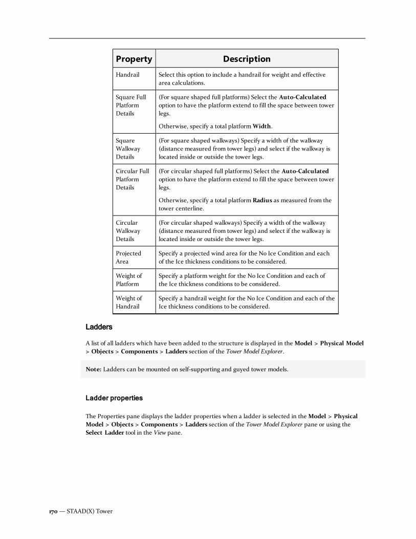
Property Description
Handrail Select this option to include a handrail for weight and effectivearea calculations.
Square FullPlatformDetails
(For square shaped full platforms) Select the Auto-Calculatedoption to have the platform extend to fill the space between towerlegs.
Otherwise, specify a total platformWidth.
SquareWalkwayDetails
(For square shaped walkways) Specify a width of the walkway(distance measured from tower legs) and select if the walkway islocated inside or outside the tower legs.
Circular FullPlatformDetails
(For circular shaped full platforms) Select the Auto-Calculatedoption to have the platform extend to fill the space between towerlegs.
Otherwise, specify a total platform Radius as measured from thetower centerline.
CircularWalkwayDetails
(For circular shaped walkways) Specify a width of the walkway(distance measured from tower legs) and select if the walkway islocated inside or outside the tower legs.
ProjectedArea
Specify a projected wind area for the No Ice Condition and eachof the Ice thickness conditions to be considered.
Weight ofPlatform
Specify a platform weight for the No Ice Condition and each ofthe Ice thickness conditions to be considered.
Weight ofHandrail
Specify a handrail weight for the No Ice Condition and each of theIce thickness conditions to be considered.
Ladders
A list of all ladders which have been added to the structure is displayed in theModel > Physical Model> Objects > Components > Ladders section of the Tower Model Explorer.
Note: Ladders can be mounted on self-supporting and guyed tower models.
Ladder properties
The Properties pane displays the ladder properties when a ladder is selected in theModel > PhysicalModel > Objects > Components > Ladders section of the Tower Model Explorer pane or using theSelect Ladder tool in the View pane.
170— STAAD(X) Tower

Parameter Description
Ladder ID This program-generated number is used to identify each ladderelement.
Description (Optional) Add a short title or description of the ladderelement.
Start Height Specify the elevation (global Y coordinate) of the bottom of thetower.
Note: Start height should be greater than or equal to theelevation at base of the tower model. Start height shouldalso be less than the total tower height.
End Height Specify the elevation (global Y coordinate) of the top of theladder.
Note: End height should be greater than the Start height.End height should also not exceed the elevation of the topof the tower structure.
Has Cage Select this option if the ladder has a safety cage.
Along (Currently,ladders may only be placed on a tower face.)
Face ID (Face only) Select the tower face ID to which the ladder isattached.
Position (Face only) Select if the ladder is attached to the inside oroutside of the selected tower face.
Face Offset (Face only) Specify the offset distance from the tower face tothe ladder centerline.
Lateral Shift (Face only, Optional) Shift a ladder placed on a tower facelaterally either direction along the face. The offset is specifiedas a fraction of the face width, with positive values shifting leftand negative values shifting right.
Accepted values range from -0.5 to 0.5.
Table 8-30: Ladder Properties
Feedlines
A list of all feedlines which have been added to the structure is displayed in theModel > Physical Model> Objects > Components > Feedlines section of the Tower Model Explorer pane.
Note: Feedlines can be mounted on self-supporting and guyed tower models.
User Manual — 171
Chapter 8 Command Reference: Tower Model Explorer
8.2 Physical Model

Feedline properties
The Properties pane displays the feedline properties when a feedline is selected in theModel> Physical Model > Objects > Components > Feedlines section of the Tower Model Explorer pane orusing the Select Feedline tool in the View pane.
Parameter Description
Feedline ID This program-generated number is used to identify each feedline element.
Description
Coax Cable
Start Height Specify the elevation (global Y coordinate) of the bottom of thetower.
Note: Start height should be greater than or equal to theelevation at base of the tower model. Start height shouldalso be less than the total tower height.
End Height Specify the elevation (global Y coordinate) of the top of thefeed line.
Note: End height should be greater than the Start height.End height should also not exceed the elevation of the topof the tower structure.
Along (Currently, feed lines may only be placed on a tower face.)
Position (Face only) Select if the feed line is attached to the inside oroutside of the selected tower face.
Leg/ Face ID (Face only) Select the tower face ID to which the feed line isattached.
Note: Only one set of feed-lines can be added on a singleface.
Face Offset (Face only) Specify the offset distance from the tower face tothe feed line centerline.
Lateral Shift (Face only, Optional) Shift a feed line placed on a tower facelaterally either direction along the face. The offset is specifiedas a fraction of the face width, with positive values shifting leftand negative values shifting right.
Accepted values range from -0.5 to 0.5.
Table 8-31: Feed Line properties
172— STAAD(X) Tower

Parameter Description
ConsiderTorque
Allow Sheilding
Ka Factor (NoIce / Ice)
Libraries
User defined bracing patterns will appear here.
In order to create or edit User Defined Bracing patters, use either the Face Bracing Wizard or PlanBracing Wizard tool.
Supports
A list of all support types which have been added to the structure is displayed in theModel > PhysicalModel > Supports section of the Tower Model Explorer pane.
Adding a support type
1. Select theModel > Physical Model > Supports section of the Tower Model Explorer pane.
2. From the pop-up menu, select either
l Add Pinned Support
l Add Fixed Support
l Add Fixed-But Support
A new entry is added for the selected support type.
Next, the support type should be assigned to one or more nodes.
Assigning support types to model nodes
To assign any support, following the steps mentioned below.
Method 1
1. From the Model ribbon tab, click the Node Selection cursor.
2. Select the desired support type in the navigation explorer
3. Select the target node/ nodes
4. Move the mouse over the selected support in the navigation explorer
5. Assign pop-up menu will appear near the selected support item
6. Select Assign pop-up menu item
User Manual — 173
Chapter 8 Command Reference: Tower Model Explorer
8.2 Physical Model

Method 2
1. Chose the Node Selection cursor
2. Select the target node/ nodes
3. In the node(s) property list, select the desired kind of support from the list.
Method 3
1. Open the Nodes Table in the output pane.
2. Select the row that contains the target node information.
3. Change the cell value under the support column.
Editing a fixed-but support type
Note: Both Fixed and Pinned supports are pre-defined and their properties cannot be edited.
1. Select the support type in theModel > Physical Model > Supports section of the TowerModel Explorer pane.
2. The parameters are displayed in the Properties pane.
3. Select the correspond options to release either force or moment in the indicated direction.
4. Spring constants can be defined instead of releases in the second panel.
Display the Support Assignments table
1. Select the Model > Physical Model > Supports section of the Tower Model Explorer pane.
2. From the pop-up menu, select Show Support Assignment Table.
The Support Assignment table opens in the Output pane.
Loads
Physical loads will be grouped in this section of the Tower Model Explorer pane.
Load Generation Parameters
STAAD(X) Tower includes tools for rapidly adding code defined wind and seismic loads to your towermodel.
174— STAAD(X) Tower

Wind/Ice Load Definitions per TIA/EIA-222 codes
The parameters for a TIA/EIA 222G or 222F wind/ice load are displayed in the properties
Property Description
ReferenceNumber
A value automatically generated by the application (non editable).
Description You may provide a brief description here for identifying theparameter set. Any alpha-numeric string is allowed.
Sate Select the target US State name from the all exhaustive list.
County Select the target county name pertaining to the selected state.
Basic WindSpeed
For the specified geographic location (state/ county combination);retrieved from the TIA database.
Note: The basic wind speed information (EIA/TIA-222-F)cannot be modified.
WindAzimuths
By default 0 deg, 45 deg, 90 deg for a square structure, and 0 deg,60 deg, and 90 deg for a triangular structure (non editable).
Ice Load Select this option if ice load is required for this tower model loaddefinition.
Type of Ice Select either solid or rime as per requirement.
Ice Density This value is determined based on type of ice selected above(normally 56 lb/ft3 for solid ice and 30 lb/ft3 for rime ice).
Ice Thickness This value is retrieved from the TIA database based on geographiclocation but you may edit if necessary.
Wind Speed(Ice)
This is the concurrent wind speed with ice load. This will defaultto 75% of the basic wind speed without ice, but you may edit it ifnecessary.
Wind Speed(Service)
Specify a wind speed used for service load conditions.
Note: The default is 50 mph, as specified in the TIA-222Fcode. A warning dialog box opens if this value is edited.
Table 8-32: TIA-222FWind Type properties
User Manual — 175
Chapter 8 Command Reference: Tower Model Explorer
8.2 Physical Model

Property Description
Load Cases Select which load type and direction you want to be generated asa primary load case. Any or all of the following six different sets ofload cases can be added based on this definition:
l wind without ice from 0 degree
l wind without ice from 45 / 60 degree
l wind without ice from 90 degree
l concurrent wind with ice from 0 degree
l concurrent wind with ice from 45 / 60 degree
l concurrent wind with ice from 90 degree
Note: Any of these load cases, when applied, will createcorresponding reference load case that can be assigned bythe user on the entire model.
Property Description
ReferenceNumber
A value automatically generated by the application (noneditable).
Description You may provide a brief description here for identifying theparameter set. Any alpha-numeric string is allowed.
Sate Select the target US State name from the all exhaustive list.
County Select the target county name pertaining to the selected state.
No Ice The basic wind speed without ice for the specified state/ countycombination retrieved from the TIA database
Ice for the specified state/ county combination retrieved from theTIA database
Note: The minimum basic wind speed and minimum icethickness per TIA-222-G cannot be considered for theanalysis and design.
Service for the specified state/ county combination retrieved from theTIA database
WindAzimuths
By default 0 deg, 45 deg, 90 deg for a square structure, and 0deg, 60 deg, and 90 deg for a triangular structure (non editable).
Thickness The ice thickness value is retrieved from the TIA database basedon geographic location but you may edit if necessary.
Density Normally an ice density of 56 lb/ft3 is used.
Table 8-33: TIA-222GWind Type properties
176— STAAD(X) Tower

Property Description
Classification Class I / Class II / Class III as per requirement, based on usage ofthe structure.
Type Tower structures are considered latticed structures.
ExposureCategory
Select wind exposure category B / C / D as dictated bysurrounding site conditions.
Category You must select the appropriate topographic categorydescription as per code requirement.
Height ofCrest (H)
For topographic categories 2, 3, and 4, you must also specify theheight of the escarpment, hill, or ridge on which the structure islocated.
TopographicFactor (Kzt)
For topographic category 5, you must specify a site specifytopographic factor.
Load Cases Select which load type and direction you want to be generated asa primary load case. Any or all of the following nine different setsof load cases can be added based on this definition:
l wind without ice from 0 degree
l wind without ice from 45 / 60 degree
l wind without ice from 90 degree
l concurrent wind with ice from 0 degree
l concurrent wind with ice from 45 / 60 degree
l concurrent wind with ice from 90 degree
l wind (service) from 0 degree
l wind (service) from 45 / 60 degree
l wind (service) from 90 degree
Note: Any of these, when applied, will create correspondingreference load case that can be assigned by the user on theentire model.
Note: The Ka factor for linear and discrete appurtenances per TIA-222-G cannot be modified. Theprogram considers Ka =1 by default.
Seismic Load definitions per TIA/EIA-222G code
The parameters for a TIA/EIA 222G seismic load are displayed in the properties
User Manual — 177
Chapter 8 Command Reference: Tower Model Explorer
8.2 Physical Model

Property Description
ReferenceNumber
A value automatically generated by the application (noneditable).
Description You may provide a brief description here for identifying theparameter set. Any alpha-numeric string is allowed.
AnalysisProcedure
Only Method 1 as described in the code is currently supported
Classificationof Structure
Select either Class I / Class II / Class III as per requirement
ImportanceFactor
Taken from Table 2-3 in TIA-222-G, based on the classification ofthe structure.
Ss Spectral response acceleration at short period, to be specified asper requirement
S1 Maximum considered earthquake spectral response accelerationat one second, to be specified as per requirement
Site Class A to F, to be specified as per requirement
Table 8-34: TIA-222G Seismic properties
Load Groups
The Load Groups item in the navigation explorer contains the collection of user-defined reference loadcases.
A Load Group only has an inherent class (e.g., dead, live, wind, seismic, etc.) and no other parameters.However, each component load item within a load group has its unique property list where you canspecify the typical parameters for that load.
Seismic load groups
For seismic loads as per the TIA 222 G standard, if the corresponding Load Generation Parameter isdefined properly, you can the seismic load in any available reference load case.
Under such reference load cases (or load groups), you can add other types of loads as well using thepop-up menu. The other types of load items that can be added are:
l Joint Loads
l Member Loads like uniform force load, concentrated force load, uniformmoment load,concentrated moment load, trapezoidal load, and linearly varying load.
Note: The add loads pop-up menu is only available to user-created load groups. Generated load groupsmay only be assigned and cannot have additional loads added.
Adding a load group
You can add a Load Group (by default referred as Load Group followed by an unique identification
178— STAAD(X) Tower

number) under the Load Groups item in the navigation explorer.
1. Select theModel > Physical Model > Loads > Load Groups entry in the Tower ModelExplorer.
2. From the pop-up menu, select Add Load Group.
3. A new Load Group entry appears in the list below this entry.
Hint: If reference load cases for wind and / or ice are created from the Load Generation Parametersfollowing the TIA-222-F and TIA-222-G codes, then those reference load cases are added in thecollection automatically.
Changing a load type for a load group
Use the following procedure to change the load type.
1. Select the load group you want to edit from theModel > Physical Model > Loads > LoadGroups entry in the Tower Model Explorer pane.
The Load Group properties are displayed in the Properties pane.
2. Select the appropriate Load Typewhich best describes the load applied..
Assigning generated wind, ice, or seismic loads
Except the selfweight load, all other reference loads need to be assigned. Since wind, ice and seismic loadsare assigned on the entire structure, no selection is necessary for assignment.
Hint: For joint load or member load assignment, you must select the target joint(s) or member(s),respectively, prior to the assignment. This is done by individual load, rather than by load group. Refer toload types.
1. Select the load group you want to assign from theModel > Physical Model > Loads > LoadGroups entry in the Tower Model Explorer.
2. From the pop-up menu, select Assign.
Selfweight
Selfweight is the automatically calculated dead load of the physical model elements and components.
If the selfweight load was applied from the Setup Wizard, then that selfweight load gets added in thecollection Selfweight as a reference load case automatically. If this option was not selected during theSetup Wizard, then you may add a new load group and add a selfweight load to it.
Note: Once added, a selfweight load cannot be deleted from the model file.
Adding selfweight load
This procedure is not necessary if you selected the selfweight option in the new tower model wizard.
User Manual — 179
Chapter 8 Command Reference: Tower Model Explorer
8.2 Physical Model

1. Right click on the load group where you want to add selfweight on theModel > PhysicalModel > Loads > Load Groups entry in the Tower Model Explorer pane and selectSelfweight Load > Add Selfweight Load from the pop-up menu.
An entry for the selfweight load is added and the selfweight load is automatically assigned toall members and components based on their properties.
2. From the pop-up menu, select Selfweight Load > Add Selfweight Load.
3. An entry for the selfweight load is added below.
Note: The selfweight load does not need to be assigned. It will automatically be assigned toall members and components based on their properties.
In some instances, you may want to change the direction or load factor on the selfweight load once theload is added.
Selfweight properties
Displayed when theModel > Physical Model > Loads > Load Groups entry is selected in the TowerModel Explorer pane.
Property Description
Direction Select which Global direction along which the selfweight load willact. As gravity/vertical is always defined parallel to the global Yaxis in a parametric tower model, this will typically beY.
Factor Specify a ratio factor for the selfweight load. This factor will be adirect multiplier to the weight as determined by the material andgeometry properties of the members and components. Thedefault value is 1 (i.e., 100%).
Table 8-35: Selfweight Load properties
Joint Load
Joint loads, both forces and moments, may be applied to any free joint of a structure. These loads act inthe global coordinate system of the structure. Positive forces act in the positive coordinate directions.Any number of loads may be applied on a single joint, in which case the loads will be additive on thatjoint.
Adding a joint load
1. Expand theModel > Physical Model > Loads > Load Groups section of the Tower ModelExplorer pane.
2. Select the load group where you want to add a joint load.
3. From the load group's pop-up menu, select Joint Load > Add Joint Load.
4. A new joint load appears in the load group with the default properties.
180— STAAD(X) Tower

Specifying a joint load magnitude
A single joint load may have a force parallel to and a moment about each global axis. There are no otherparameters to be set for a joint load.
1. Select the joint load you want to edit.
2. The load parameters are specified in the Properties pane.
3. Edit any force or moment value and press the Return key.
Note: Enter values for Fx, Fy, Fz (forces in corresponding global directions), Mx, My and Mz(moments in corresponding global directions), as needed.
Assigning a joint load
1. Use the Node Selection tool to select the node(s) in the View pane to which you want to applythe joint load.
2. From the joint load's pop-up menu (Expand theModel > Physical Model > Loads > LoadGroups section of the Tower Model Explorer pane if you cannot see it), select Assign.
3. The load will appear on the structure in the View pane when selected in the Tower ModelExplorer pane.
Member Loads
STAAD(X) Tower provides you with three types of member loads may be applied directly to a member ofa structure. These loads are uniformly distributed loads, concentrated loads, and linearly varying loads(including trapezoidal). Uniform loads act on the full or partial length of a member. Concentrated loadsact at any intermediate, specified point. Linearly varying loads act over the full length of a member.Trapezoidal linearly varying loads act over the full or partial length of a member. During analysis,trapezoidal loads are converted into a uniform load and several concentrated loads.
You may specify any number of loads to act upon a member in any independent loading condition.Member loads can be specified in the member coordinate system or the global coordinate system.Uniformly distributed member loads provided in the global coordinate systemmay be specified to actalong the full or projected member length. Refer to the figure below to find the relation of the member tothe global coordinate systems for specifying member loads. Positive forces act in the positive coordinatedirections, local or global, as the case may be.
User Manual — 181
Chapter 8 Command Reference: Tower Model Explorer
8.2 Physical Model

Figure 8-4: Member load configuration. Variables d and w are input via the Properties pane.
Adding a member load
1. Expand theModel > Physical Model > Loads section of the Tower Model Explorer pane.
2. Select the load group to which you want to add a new member load.
3. From the load group pop-up menu, select theMember Load > menu and then select thetype of member load you want to add (refer to list of descriptions above).
4. A new member load is added to the load group with default load properties.
5. The pointer changes to a member selection cursor in the View pane. Clicking on a memberwill assign the new load.
Specifying member load magnitude and distance
1. Select the member load you want to edit using either the Select Load tool or by selecting theentry in the Tower Model Explorer pane.
2. The load properties are specified in the Properties pane.
182— STAAD(X) Tower

Assigning member load to a member
1. Use the Physical Member Selection tool to select the member(s) in the View pane to whichyou want to apply the member load.
2. From the member load's pop-up menu (Expand theModel > Physical Model > Loads> Load Groups section of the Tower Model Explorer pane if you cannot see it), select Assign.
3. The load will appear on the structure in the View pane when selected in the Tower ModelExplorer pane.
Member load properties
The following types of member load are available to you, with multiple options covering most all memberload conditions:
l A uniformmember load can be specified as either Force or Moment.
Property Description
UDL / URM The uniformly distributed load or moment is specified inthe UDL or UDM variable, respectively. Specify themagnitude of the load here, with appropriate sign (+/-).
d1 Specifies the distance from the start of the member tothe start of the uniform load.
Note: All distances (dn) are taken along the local
axis.
d2 Specifies the distance from the start of the member tothe end of the uniform load.
d3 specifies the distance from the centerline of the member(local y-axis) to the load.
Direction Select which direction to apply the force, with axis inlocal or global coordinate systems in the menu.
Table 8-36: Uniformly Distributed Load properties
l A Force or Moment applied to a single point along the length of a member.
Property Description
P The concentrated load or moment is specified by the Pvariable.
Table 8-37: Concentrated Member Load properties
User Manual — 183
Chapter 8 Command Reference: Tower Model Explorer
8.2 Physical Model

Property Description
d1 Specifies the distance from the start of the member tothe location of the concentrated load.
Note: All distances (dn) are taken along the local
axis.
d2 specifies the distance from the centerline of the member(local y-axis) to the load.
Direction Select which direction to apply the force, with axis inlocal or global coordinate systems in the menu.
l A load that varies linearly along the member's length. A Linearly Varying Load is appliedover the full length of the member whereas a Trapezoidal Loadmay act over the full orpartial length of the member. Both Linearly Varying Loads and Trapezoidal loads act throughthe centroid of the member.
Property Description
w1 Specify the magnitude of the load closest to the start ofthe member. Selecting this option and specifying thesevalues is used for either a Linear or Trapezoidal load.
w2 Specify the magnitude of the load closest to the end ofthe member. Selecting this option and specifying thesevalues is used for either a Linear or Trapezoidal load.
w3 specifies the magnitude of the load at mid-span of atriangular loading.
Note: You must select an option for specifying w1
and w2(for a linear or trapezoidal member loads) or
w3(for triangular member loads).
d1 Specifies the distance from the start of the member tothe location of the concentrated load.
Note: All distances (dn) are taken along the local
axis.
d2 specifies the distance from the centerline of themember (local y-axis) to the load.
Direction Select which direction to apply the force, with axis inlocal or global coordinate systems in the menu.
Table 8-38: Linearly Varying Load properties
184— STAAD(X) Tower

Note: If any load start or end values result in the load extending beyond the length of the member, theload is truncated to the member start or end, respectively.
Wind/ Ice Loads
There are multiple wind or wind/ ice load combination loads that you may add to your tower model.
Hint: In order to use wind/ice loads, you must first create a set of associated Wind/Ice LoadParameters or Wind Intensity (for Wind on Open Structures).
Note: Once it has been added, a wind/ice load cannot be deleted from the model file.
Adding a wind/ice load
1. Expand theModel > Physical Model > Loads > Load Groups section of the Tower ModelExplorer pane.
2. Select the load group where you want to add a wind/ ice load.
3. From the load group's pop-up menu, selectWind/ Ice Load and then the specific wind/ iceload you want to add.
4. A new load appears in the load group with the default properties.
Wind/Ice load properties
The following properties are displayed for a wind/ice load.
Property Description
Ref. No A value automatically generated by the application (non editable).
Description Add an optional description for this wind/ice parameter set.
ZoneIdentification
Select the State and Country in which the tower is located.
Wind Speed Wind speeds for No Ice, Ice, and Service conditions, as providedin the associated wind parameters (non editable).
Apply LoadCase
Select the applied load case used from the drop-down list. Thisaccounts for azimuth, inclusion of ice, and load level.
Ice Density This value is determined based on type of ice selected above(normally 56 lb/ft3 for solid ice and 30 lb/ft3 for rime ice).
Ice Thickness This value is retrieved from the TIA database based on geographiclocation (non editable).
Table 8-39: Wind/Ice 222G Load properties
User Manual — 185
Chapter 8 Command Reference: Tower Model Explorer
8.2 Physical Model
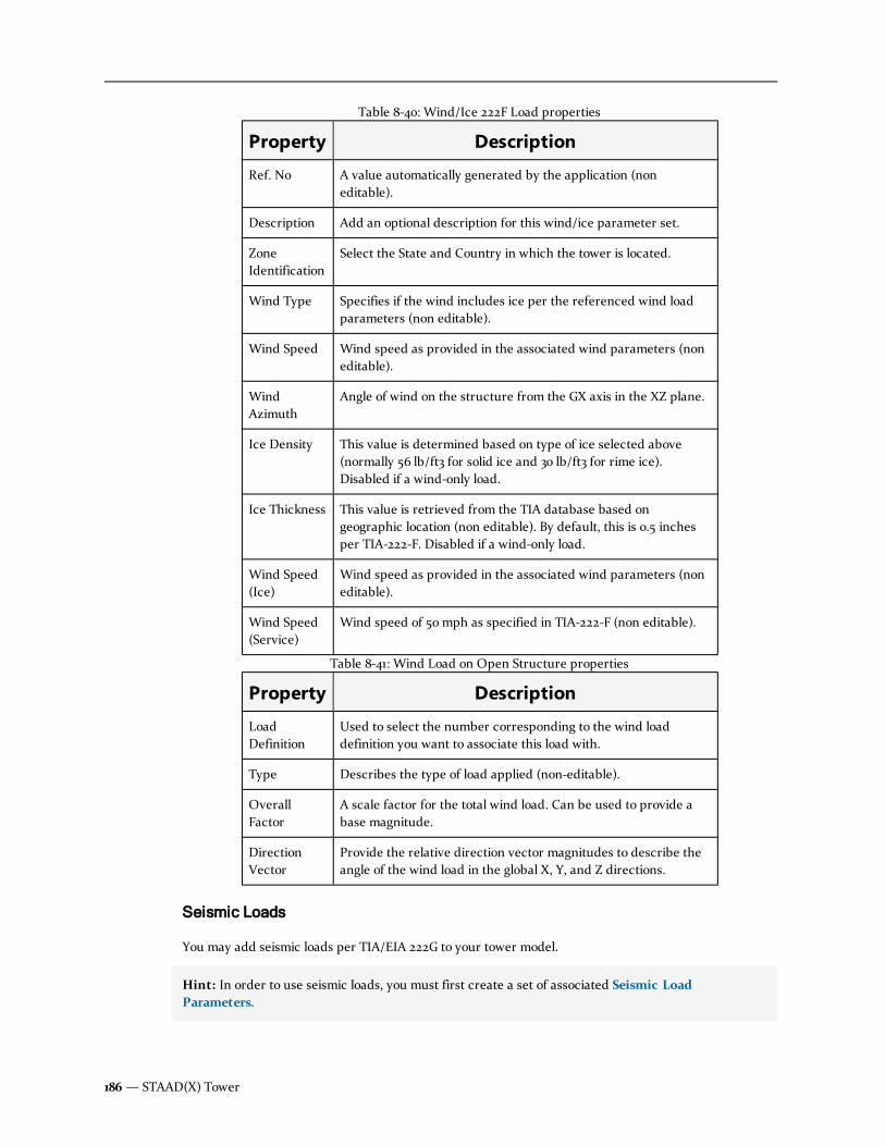
Property Description
Ref. No A value automatically generated by the application (noneditable).
Description Add an optional description for this wind/ice parameter set.
ZoneIdentification
Select the State and Country in which the tower is located.
Wind Type Specifies if the wind includes ice per the referenced wind loadparameters (non editable).
Wind Speed Wind speed as provided in the associated wind parameters (noneditable).
WindAzimuth
Angle of wind on the structure from the GX axis in the XZ plane.
Ice Density This value is determined based on type of ice selected above(normally 56 lb/ft3 for solid ice and 30 lb/ft3 for rime ice).Disabled if a wind-only load.
Ice Thickness This value is retrieved from the TIA database based ongeographic location (non editable). By default, this is 0.5 inchesper TIA-222-F. Disabled if a wind-only load.
Wind Speed(Ice)
Wind speed as provided in the associated wind parameters (noneditable).
Wind Speed(Service)
Wind speed of 50 mph as specified in TIA-222-F (non editable).
Table 8-40: Wind/Ice 222F Load properties
Property Description
LoadDefinition
Used to select the number corresponding to the wind loaddefinition you want to associate this load with.
Type Describes the type of load applied (non-editable).
OverallFactor
A scale factor for the total wind load. Can be used to provide abase magnitude.
DirectionVector
Provide the relative direction vector magnitudes to describe theangle of the wind load in the global X, Y, and Z directions.
Table 8-41: Wind Load on Open Structure properties
Seismic Loads
You may add seismic loads per TIA/EIA 222G to your tower model.
Hint: In order to use seismic loads, you must first create a set of associated Seismic LoadParameters.
186— STAAD(X) Tower

Seismic load properties
Displayed when theModel > Physical Model > Loads > Load Groups section of the Tower ModelExplorer pane is selected.
Direction
Select which Global (GX or GZ) direction the selfweight load will act along.
8.3 AnalysisThe Analysis branch of the Tower Model Explorer pane contains all the information for analytical modelentities such as member segments, nodes, and primary load cases.
Whole Model
The Whole Model is the default analysis model. As the name suggests, this is a mathematical model whichis decomposed from the entire physical model for the purpose of analysis.
When the Whole Model is selected, the Properties pane displays options used to specify the method ofanalysis to be used by the STAAD engine along with details for the selected method.
Analysis model properties
Displayed when the Analysis > Whole Model section of the Tower Model Explorer pane is selected.
Property Description
Method Select one of the following analysis methods from the drop-downlist:
l 1st Order Analysis
l P-Delta Analysis
No ofIteration
For either 1st Order Analysis or P-Delta Analysis methods, youmust specify the number of iterations the program shall use.
The default number of iterations is set to one (1) for the P-Deltaoptions. Between 3 and 30 iterations is a recommended range formost structures.
Table 8-42: Analysis Model properties
User Manual — 187
Chapter 8 Command Reference: Tower Model Explorer
8.3 Analysis
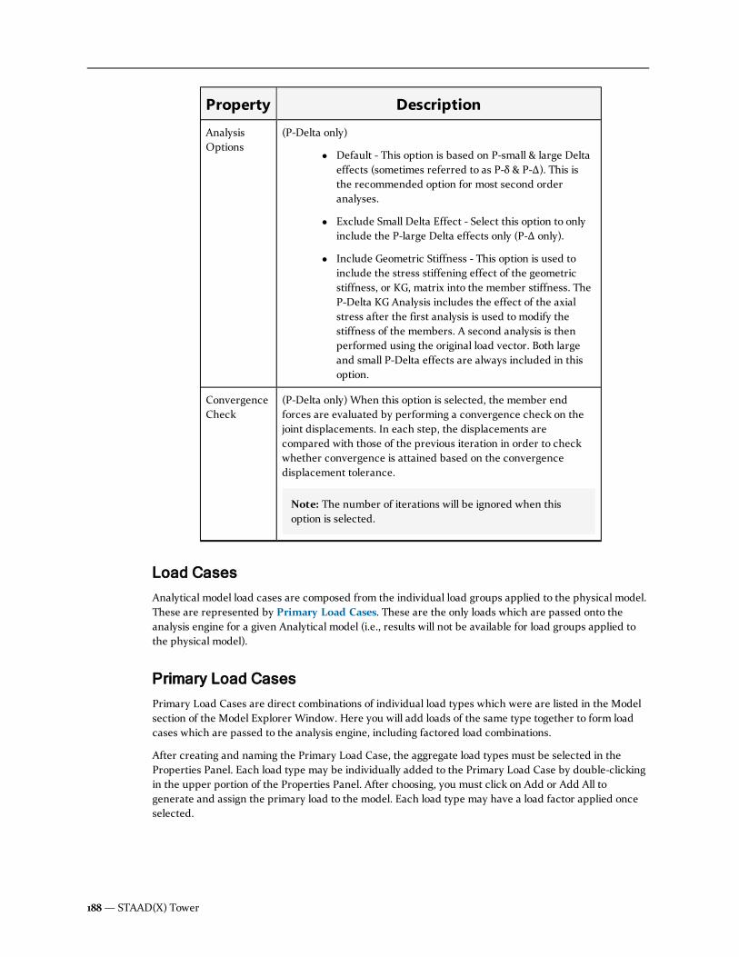
Property Description
AnalysisOptions
(P-Delta only)
l Default - This option is based on P-small & large Deltaeffects (sometimes referred to as P-δ & P-Δ). This isthe recommended option for most second orderanalyses.
l Exclude Small Delta Effect - Select this option to onlyinclude the P-large Delta effects only (P-Δ only).
l Include Geometric Stiffness - This option is used toinclude the stress stiffening effect of the geometricstiffness, or KG, matrix into the member stiffness. TheP-Delta KG Analysis includes the effect of the axialstress after the first analysis is used to modify thestiffness of the members. A second analysis is thenperformed using the original load vector. Both largeand small P-Delta effects are always included in thisoption.
ConvergenceCheck
(P-Delta only) When this option is selected, the member endforces are evaluated by performing a convergence check on thejoint displacements. In each step, the displacements arecompared with those of the previous iteration in order to checkwhether convergence is attained based on the convergencedisplacement tolerance.
Note: The number of iterations will be ignored when thisoption is selected.
Load Cases
Analytical model load cases are composed from the individual load groups applied to the physical model.These are represented by Primary Load Cases. These are the only loads which are passed onto theanalysis engine for a given Analytical model (i.e., results will not be available for load groups applied tothe physical model).
Primary Load Cases
Primary Load Cases are direct combinations of individual load types which were are listed in the Modelsection of the Model Explorer Window. Here you will add loads of the same type together to form loadcases which are passed to the analysis engine, including factored load combinations.
After creating and naming the Primary Load Case, the aggregate load types must be selected in theProperties Panel. Each load type may be individually added to the Primary Load Case by double-clickingin the upper portion of the Properties Panel. After choosing, you must click on Add or Add All togenerate and assign the primary load to the model. Each load type may have a load factor applied onceselected.
188— STAAD(X) Tower

Analytical Objects
The physical model is decomposed into analytical objects for the purpose of analysis. Selecting theModel> Analysis > Whole Model > Analytical Objects section of the Tower Model Explorer pane displays theanalytical model for review.
See Also: View Modes
Nodes
A list of all analytical nodes is displayed under this entry of the Tower Model Explorer pane. These entitiesare not directly editable. You must edit the physical model elements.
Members
A list of all analytical members is displayed under this entry of the Tower Model Explorer pane. Theseentities are not directly editable. You must edit the physical model elements.
Results
Upon performing an analysis on the model, tables and graphs of the results of that analysis will beavailable in this section of the Tower Model Explorer.
Displacements Results
Results on the geometric displacement of the tower structure elements under applied loads are foundhere.
Node Displacements
This section provides you with a table for the displacements and rotations at each analytical node in themodel for every primary load case. The table includes displacements parallel to the global coordinatesystem, as well as the resultant displacement distance, and the rotation of the node about each of theglobal axis.
Deflected Profile
Horizontal Deflection
Used to display the horizontal deflection graph for the structure.
Tilt
Used to display the tilt graph for the tower structure.
Twist
Used to display the twist graph for the tower structure.
Displaying the joint displacement table
1. Select theModel > Analysis >Whole Model > Results > Displacement Results > NodeDisplacements section of the Tower Model Navigator.
User Manual — 189
Chapter 8 Command Reference: Tower Model Explorer
8.3 Analysis

2. From the pop-up menu, select Show Joint Displacements Table.
3. The table is displayed on the Joint Displacements Table tab in the Output pane.
Force Results
Results on the internal forces and stresses of the tower structure elements under applied loads arefound here.
Linear Members
Display Member End Forces
Used to open the Member End Force table, which displays the forces and moments in alldegrees of freedom at the either end of each analytical member segment.
Force/ Displacements
Used to open the Physical Member results query dialog by selecting a member of interest inthe View pane.
Member Force Graphs
Used to open the Member Force Diagrams tab in the Output pane by selecting a member ofinterest in the View pane.
Member Stresses
Used to open the Member Section Stresses query in the Properties pane by selecting amember of interest in the View pane.
Displaying leg compression curves
For each leg of the tower structure, STAAD(X) Tower generates envelope diagrams of the axialcompression along that leg's height. To view a specific leg's compression curve:
1. Under theModel > Analysis >Whole Model > Results > Force Results > LegCompression Curves section of the Tower Model Navigator, select the entry for the leg youwant to inspect.
2. The compression curve with the envelop of analyzed loads for the selected leg is thendisplayed in the Properties pane.
190— STAAD(X) Tower

Reaction Results
Results on the tower structure boundary conditions under applied loads are found here.
8.4 DesignThe Design branch of the Tower Model Explorer pane displays results of your member code check fordesigning tower structures.
Note: Design results are not available until a successful analysis and code check are performed.
User Manual — 191
Chapter 8 Command Reference: Tower Model Explorer
8.4 Design

192— STAAD(X) Tower
Chapter 8
8.4 Design

Chapter 9
Tutorials
This section contains several tutorial examples which you can follow to further explore the program.
9.1 Tutorial for Self-Supporting Tower 194
9.2 Tutorial for Monopole Tower 202
9.3 Tutorial for Guyed Tower 206
9.4 Create custom panel bracing pattern 209
User Manual — 193

9.1 Tutorial for Self-Supporting Tower
Create a Basic Self-Supporting Structure
1. Launch STAAD(X) Tower
2. Select Create a New Model link in the Start Page’s Project Task panel.
The Setup Wizards dialog box opens displaying the welcome page.
3. Select Self- Supporting type of tower.
4. Select the Next > tool to proceed to the Setup Wizard for Self- Supporting Towers.
5. Provide the following set of mandatory input in the Setup Wizard
A. A. General Tower Properties:
l Tower Name:
l Tower Description:
l Country Code: US
194— STAAD(X) Tower
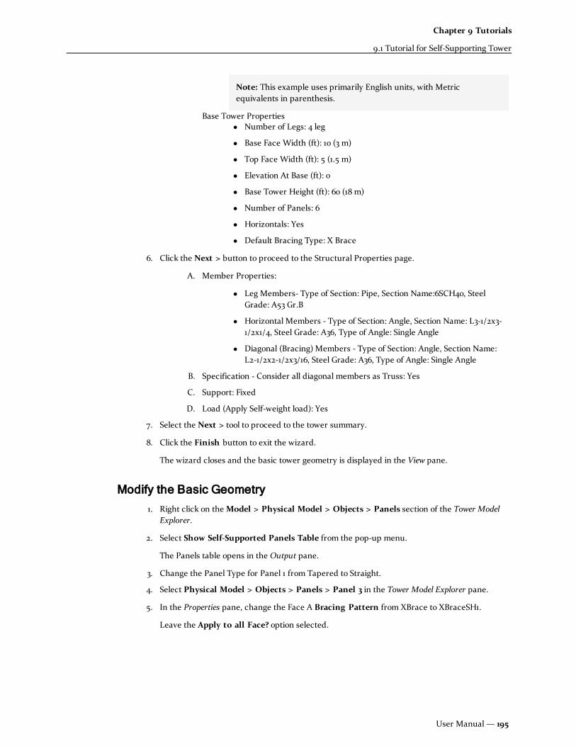
Note: This example uses primarily English units, with Metricequivalents in parenthesis.
Base Tower Propertiesl Number of Legs: 4 leg
l Base Face Width (ft): 10 (3 m)
l Top Face Width (ft): 5 (1.5 m)
l Elevation At Base (ft): 0
l Base Tower Height (ft): 60 (18 m)
l Number of Panels: 6
l Horizontals: Yes
l Default Bracing Type: X Brace
6. Click the Next > button to proceed to the Structural Properties page.
A. Member Properties:
l Leg Members- Type of Section: Pipe, Section Name:6SCH40, SteelGrade: A53 Gr.B
l Horizontal Members - Type of Section: Angle, Section Name: L3-1/2x3-1/2x1/4, Steel Grade: A36, Type of Angle: Single Angle
l Diagonal (Bracing) Members - Type of Section: Angle, Section Name:L2-1/2x2-1/2x3/16, Steel Grade: A36, Type of Angle: Single Angle
B. Specification - Consider all diagonal members as Truss: Yes
C. Support: Fixed
D. Load (Apply Self-weight load): Yes
7. Select the Next > tool to proceed to the tower summary.
8. Click the Finish button to exit the wizard.
The wizard closes and the basic tower geometry is displayed in the View pane.
Modify the Basic Geometry
1. Right click on theModel > Physical Model > Objects > Panels section of the Tower ModelExplorer.
2. Select Show Self-Supported Panels Table from the pop-up menu.
The Panels table opens in the Output pane.
3. Change the Panel Type for Panel 1 from Tapered to Straight.
4. Select Physical Model > Objects > Panels > Panel 3 in the Tower Model Explorer pane.
5. In the Properties pane, change the Face A Bracing Pattern from XBrace to XBraceSH1.
Leave the Apply to all Face? option selected.
User Manual — 195
Chapter 9 Tutorials
9.1 Tutorial for Self-Supporting Tower

Hint: You can also update panel bracing patterns from within the Panels table. Make sureto update each face if you perform this action in the table.
6. Repeat steps 4 and 5 so that all faces in Panel 4 use the KBraceDown pattern, all faces inPanel 5 use the DoubleK1BraceDown pattern, and all faces in Panel 6 use the K2BraceDownpattern.
Hint: At any point of time you can switch to the View page to explore the different viewing utilities(like physical/analytical model, member filters such as only legs/horizontals/bracing members, facewise views, etc.)
Add Antennas and Appurtenances
1. Select the Antenna tool found on the Components ribbon tab.
The mouse pointer changes to the Add Antenna cursor in the View pane.
2. Click on Leg B near the of panel 4 to place the antenna.
Hint: If you need to place the antenna on a different leg, simply select a different Leg ID inthe Antenna's property list.
3. Select the Antenna using either the Select Antenna tool (found on the Model tab)
or
by selecting the entry in the Tower Model Explorer pane,
and then change theModel Name to a P-180-6r.
Hint: You can begin typing the Model Name in the field to quickly find it's entry in thedrop-down list.
4. Repeat Steps 2 through 3 to add a #05223 model dish antenna to Leg A at the top of Panel 2.
5. Select the Appurtenance tool found on the Components ribbon tab.
The mouse pointer changes to the Add Appurtenance cursor in the View pane.
6. Click on Leg B near the top of Panel 1, approximately where you would like to place theappurtenance.
Hint: The point clicked will be the height of the bottommost duct of the appurtenance;limited to the top of the tower. Therefore, you should click somewhere in the middle of theleg member.
7. Select the Appurtenance using either the Select Appurtenance tool,
or
by selecting the entry in the Tower Model Explorer pane,
196— STAAD(X) Tower

and then change the Offset Distance to 10 in (25 cm) the Description to a2980.005/2980.015.
8. Repeat steps 5 through 7 to add a 06010 Omni to Leg D near the top of Panel 2 and a DV70-10to Leg D near the top of Panel 1. Change the Offset Distance of the DV70-10 to 12 in. (30cm) and the Azimuth angle to -30.0 degrees.
Add Platforms, Ladders, and Feed Lines
1. Select theWork Platform tool found on the Components ribbon tab.
A new Platform is added to theModel > Physical Model > Objects > Components > WorkPlatforms section of the Model Tower Explorer window. This item is selected and theproperties are displayed in the Properties pane.
2. Specify the Elevation Above Base as 60.0 ft (18 m), which corresponds to the top of thetower.
The work platform is displayed in the View pane.
3. Remove the check from the Auto Calculated option in the Square Full Platform Details andspecify aWidth of 10.0 ft (3 m).
4. Select the Feed Line tool found on the Components ribbon tab.
A new Feed Line is added to theModel > Physical Model > Objects > Components> Feedlines section of the Model Tower Explorer window. This item is selected and theproperties are displayed in the Properties pane.
5. Specify the End Height and Start Height as 55 ft (16.5 m) and 2 ft (0.67 m), respectively.
Hint: Enter the End Height first, as the program will not allow a Start Height that exceedsthe value of the End Height.
The feed line is displayed in the View pane.
6. Change the Face Offset to 10 in. (25 cm) and the Lateral Shift to -0.25.
7. Select the Ladder tool found on the Components ribbon tab.
A new Ladder is added to theModel > Physical Model > Objects > Components> Ladders section of the Model Tower Explorer window. This item is selected and theproperties are displayed in the Properties pane.
8. Specify the End Height as 60 ft (18 m).
The ladder is displayed in the View pane.
9. Change the Face Offset distance to 12 in. (30 cm) and the Face Id to B.
Add Loads
1. Right-click theModel > Physical Model > Loads > Load Generation Parameters section ofthe Tower Model Explorer pane and select Add Wind/Ice Parameters > TIA/EIA[222G]Definition from the pop-up menu.
2. In the Properties pane, set the following parameters:
User Manual — 197
Chapter 9 Tutorials
9.1 Tutorial for Self-Supporting Tower

l Zone Identification is set to Dade County, Florida.
l Structure Classification = Class II
l Exposure Category = D
l Select Load Cases for Wind (No Ice) = 0 degree, 45 degree, and 90 degree.
Hint: A new Load Group is selected for each of the Load Case options selected in the LoadDefinition properties.
3. Right-click theModel > Physical Model > Loads > Load Generation Parameters sectionof the Tower Model Explorer pane and select Add Seismic Parameters > TIA/EIA[222G]Definition from the pop-up menu.
4. In the Properties pane, set the following parameters:
l Structure Classification = Class II
l Site Class = C
5. Right click theModel > Physical Model > Loads > Load Groups section of the TowerModel Explorer pane and select Add Load Group from the pop-up menu.
6. Right click on this new Load Group and select Seismic Load > Add Seismic [TIA-222G]Load from the pop-up menu.
A new Seismic Load entry is added to the Load Group with the default direction of GX.
7. Repeat Steps 5 and 6 to add a second Seismic Load. Set the direction of this load toGZ.
8. Assign the Wind/Ice and Seismic load groups to the model by right clicking each in the TowerModel Explorer pane and selecting Assign.
The load icon in the Tower Model Explorer tree turns green once the load has beensuccessfully assigned. No element selection is necessary to assign wind/ice or seismic loadsand no assignment is necessary for selfwieght loads.
Create Primary Loads and Perform Analysis
1. Right-click theModel > Analysis > Whole Model > Load Cases > Primary section of theTower Model Explorer pane and select Add Primary Load Case from the pop-up menu.
2. In Properties pane, select (Select All) for Load Group Type.
All the Load Groups are listed in the Available Load Groups table.
3. Select both Load Group 1 and 2 in the list and select the Add tool.
Hint: Hold the CTRL key down to select multiple load groups.
4. Repeat Steps 1 through 3 to create the following primary load cases:
198— STAAD(X) Tower

PrimaryLoad Case
No.
ComponentLoad Group
No.s
1 1, 2: DL + W0
2 1, 3: DL + W45
3 1, 4: DL + W90
4 1, 5: DL + EX
5 1, 6: DL + EZ
5. Select the Run Analysis tool from the Model ribbon tab.
Note: If you have not saved the file, you will be prompted to save the tower file prior toanalysis.
The analysis process is displayed in the output window.
Review Analysis Results
1. Select the Results > Displacement Results > Node Displacements section of the TowerModel Explorer pane.
The Joint Displacement table opens in the Output pane.
2. Select the Results > Force Results > Linear Members > Member End Forces section of theTower Model Explorer pane.
The Member End Forces table in the Output pane.
3. Select the Results > Reaction Results > Reactions section of the Tower Model Explorer pane.
The Support Reaction table in the Output pane.
4. On the Results ribbon tab, select the any of the Axial Force, Shear Y Force, Shear Z Force,Torsion, Bending Moment Y, Bending Moment Z, Displacement, Beam Stress, and SupportReaction tools
The corresponding diagrams are displayed on the structure in the View pane.
5. Select the Show Result Box tool and then select any physical member.
The Results dialog box opens which can then be used to display the internal forces anddisplacements anywhere along the physical member length.
Hint: You may need to select the Select Physical Member tool on either the Model or Viewribbon tabs, if not selected earlier.
User Manual — 199
Chapter 9 Tutorials
9.1 Tutorial for Self-Supporting Tower

Hint: You may select any other physical member and the dialog box opens. Select theShow Result Box tool again to close the dialog box when you are finished.
6. Select the Show Force Graph tool and then select any physical member.
The graph opens in the Output pane.. Now move the slider at different distances to seedifferent member forces.
Hint: Select the Show Force Graph tool again to close the dialog box when you arefinished.
7. Select Show Member Stress tool and then select any physical member.
The Corner Stresses dialog box opens in the Properties pane.
The slider tool can be used to display the Corner stresses anywhere along the length of themember.
Hint: Select the Show Member Stress tool again to close the dialog box when you arefinished.
8. Expand the Results > Displacement Results > Deflected Profile section of the TowerModel Explorer pane and select the Horizontal Deflection, Tilt, and Twist entries in thenavigation pane.
The corresponding deflection diagrams are individually displayed on the structure in theProperties pane.
9. Select the Results > Force Results > > Leg Compression Curves > Leg A section of theTower Model Explorer pane.
The corresponding leg compression graph is displayed in the Properties pane..
Repeat this step for other legs to view the corresponding diagrams.
Perform Member Design and Review Results
1. Select TIA-222-G as the Active Design Code from the Model ribbon tab.
2. Select the Check Slenderness tool.
Any members which do not meet slenderness criteria per the selected code are listed in theOutput pane. Selecting the entry will also highlight this member in the View pane.
3. Select the Code Check tool.
The progress of the code check is displayed in the Output pane.
4. Select Show All Results tool from the Results ribbon tab.
The Design Results table opens in the Output window to display the critical information forall members. Members which have failed a design check are highlighted in the View window.
5. Select the Show Selective Result tool and select any physical member.
This will display a table comprising of detail design results for the selected physical member
200— STAAD(X) Tower

Edit Members and Re-Design
1. Select the Split Physical Leg Members tool found on the Tools ribbon tab.
The Split Tower Leg Members dialog box opens.
2. Select Top of Panel ID 1 on the Panel End tab and click the Add button.
Each of the continuous leg members are broken into separate members at the top of thebottom-most panel.
3. Select the Done tool to close the dialog.
4. Select the Structure Property Catalog tool found on the Tools ribbon tab.
5. Use the filters to select a 8SCH40 Pipe from the AISC: 13 Ed. catalog with A53 Gr. B steel.
6. Select the Add Profile + Material tool.
The new section profile is added to theModel > Physical Model > Properties > Profilessection of the Tower Model Explorer pane.
7. Select the physical leg member sections in the bottom-most panel (Physical Members 1through 4) and select the Pipe8SCH40 profile for their section.
Hint: This can be performed by using the Select Physical Member tool in the View paneor by selecting the Physical Members in the theModel > Physical Model > Objects >Members > Legs section of the Tower Model Explorer pane.
8. Perform the Analysis and Design steps again to review results of the updated model.
User Manual — 201
Chapter 9 Tutorials
9.1 Tutorial for Self-Supporting Tower

9.2 Tutorial for Monopole Tower
Create a Tapered Monopole Structure
1. Launch STAAD(X) Tower
2. Select Create a New Model link in the Start Page’s Project Task panel.
The Setup Wizards dialog box opens displaying the welcome page.
3. SelectMonopole type of tower.
4. Select the Next > tool to proceed to the Setup Wizard.
5. Provide the following set of mandatory input in the Setup Wizard for Monopoles.
A. General Tower Properties
l Country Code: US
l Design Code: TIA-222-G
B. Monopole Tower Properties
l Type of Monopole: Tapered
l Elevation At Base (ft): 0
202— STAAD(X) Tower

l Base Tower Height (ft): 120
l Number of Section: 4
l Number of Sides: OctDecagonal (18)
l Select the option to include a Round Monopole Extension.
C. Member Properties
l Type of Section: Tapered Tube
l Depth/Dia of Tube at top (in): 24
l Tube Thickness at top (in): 0.25
l Tube thickness at base (in): 0.50
l Galvanizing thickness (in): 0.0625
l Tapered factor (in/ft): 0.3
l Material & Grade: Steel / A572 Gr. 65
l Default Support - Fixed
l Self weight Load - Applied
Hint: At any point of time you can switch to the View page to explore the different viewing utilities (likephysical/analytical model, member filters such as only legs/horizontals/bracing members, face wiseviews, etc.)
Create Primary Loads and Perform Analysis
1. Right click on theModel > Physical Model > Objects > Sections entry in the Tower ModelExplorer pane.
2. Select Show Tapered Pole Sections Table from the pop-up menu.
The Pole Sections table opens in the Output pane
3. Select Pole Section 4 and change the Length value to 30 ft.
4. Select the Model > Physical Model > Profile >Add Pipe entry in of the Tower Model Explorerpane.
5. Select A Section Explorer window will open up
6. Click Search Button and select the Section Named PIPE8XXS, PIPE6XXS, PIPE5XXS and Clickthe Add ToModel button one by one
7. Select the Physical Member Cursor and select the Physical Member corresponding to PoleSection 2
8. In the properties pane change the Section from PIPE10SCH60 to PIPE8XXS in the sectionscombo box
9. Next select the Physical Member corresponding to Pole Section 3
10. In the properties pane change the Section from PIPE10SCH60 to PIPE6XXS in the sectionscombo box
11. Next select the Physical Member corresponding to Pole Section 4
User Manual — 203
Chapter 9 Tutorials
9.2 Tutorial for Monopole Tower

12. In the properties pane change the Section from PIPE10SCH60 to PIPE5XXS in the sectionscombo box
Add Components and Loads
1. Select theMonopole Mount tool from the Component ribbon tab.
The mouse pointer changes to the Add Monopole Mount cursor in the View pane.
2. Click on the Tower Model at a desired position
3. Repeat the above step for two times and thus three platforms are mounted on the model
4. Visit Physical Model > Components > Platforms to see those platforms
5. In the Tower Model Explorer pane, select Load > Load Generation Parameters
6. Select Add Wind/Ice Parameters and then select TIA/EIA[222G] Definition
7. In the Properties pane change the classification option to Class II and make the Exposurecategory to option D
8. Explore the option Load Cases and check the wind (no ice) load case option for 0 degree, withice 45 degree.
Simultaneously Load Groups are generated in the navigation window.
9. Explore the load groups and right click on the individual load groups and click the Assignoption to assign Load Groups to the model
Analysis
1. In the Tower Model Explorer pane, select Analysis > Whole Model > Load Cases > Primary
2. From the pop-up menu of Primary tree node create a new primary load case, i.e., PrimaryLoad Case1
3. Select the option Primary Load Case1 and then select Load group 1 and 2 and click add
4. From the pop-up menu of Primary tree node create a new primary load case, i.e., PrimaryLoad Case2
5. Select the option Primary Load Case2 and then select Load group 1 and 3 and click add
6. From the pop-up menu of Primary tree node create a new primary load case, i.e., PrimaryLoad Case3
7. Select the option Primary Load Case3 and then select Load group 1 and 4 and click add
8. From the pop-up menu of Primary tree node create a new primary load case, i.e., PrimaryLoad Case4
9. Select the option Primary Load Case4 and then select Load group 1 and 5 and click add
10. To analyze the model go to Run Analysis menu item in the tool bar and click it. You will beasked to save the tower file prior to analysis
Post Analysis Results
1. In the Tower Model Explorer pane, select Results > Displacement Results > NodeDisplacements. Thus you can view the Joint Displacement Table in the output pane
204— STAAD(X) Tower

2. Select Results > Force Results > Linear Members > Member End Forces. This will bring up theMember End Forces Table in the output pane
3. Select Results > Reaction Results > Reaction to see the Support Reaction Table in a similar way
4. From the Model page go to the Results page
5. Select the buttons named Axial Force, Shear Y Force, Shear Z Force, Torsion, Bending MomentY, Bending Moment Z, Displacement, Beam Stress, and Support Reaction all available in thetool bar one by one to see the corresponding diagrams respectively
6. Chose physical member selection cursor, if not selected earlier
7. Select the Show Result Box button in the tool bar and then select any physical member. A pop-up window will appear which will show the changing values with the change in length
8. Toggle off the Show Result Box Button
9. Select Show Member Stress button in the tool bar and then select any physical member. Aproperty pane will appear which will show the Corner stresses by varying the slider
10. Select the Show Force Graph button in the tool bar and then select any physical member. Thegraph will appear in the output pane. Now move the slider at different distances to seedifferent member forces
11. Toggle off the Show Force Graph button
12. Select Show Member Stress button in the tool bar and then select any physical member. Thecorresponding UI will appear in the property pane. By varying the slider measure the Cornerstresses.
13. Toggle off the Show Member Stress button
14. Select Results > Displacement Results > Deflected Profile > Horizontal Deflection in thenavigation pane. The deflection diagram will appear in the property pane
15. Select Results > Displacement Results > Deflected Profile > Tilt in the navigation pane. The tiltdiagram will appear in the property pane
16. Select Results > Displacement Results > Deflected Profile > Twist in the navigation pane. Thetwist diagram will appear in the property pane
17. To performMember Design go back to the Model page and select the menu item named TIA-222-G and then Check Code
18. Once the code checking is performed successfully, switch back to the Results page.
19. Select Show All Results button in the tool bar. This will generate a table comprising of criticalinformation for all members along with graphical representation of the failed and passedmembers
20. Toggle off the Show All Results button
21. Select the Show Selective Result button in the tool bar and select any physical member. Thiswill display a table comprising of detail design results for the selected physical member
Report Generation
1. Select Report Button in the toolbar. Explore the tree node named Reports and drag theelements which you want to view in the Report Entity Pane
2. The reports will be generated and click the option Export To in the toolbar and select thedesired file format you want and save the file
User Manual — 205
Chapter 9 Tutorials
9.2 Tutorial for Monopole Tower

9.3 Tutorial for Guyed Tower1. Launch STAAD(X) Tower
2. Select Create a New Model link in the Start Page’s Project Task panel
3. In the Setup Wizards welcome page select Guyed type of tower
4. Provide the following set of mandatory input in the Setup WizardA. Base Tower Properties
l Number of Legs: 4 leg
l Elevation At Base (ft): 0
l Base Tower Height (ft): 100
l Base Face Width (ft):5
l Tapered At Base: Yes
l Horizontals: Yes
l Number of Panels: 10
l Number of Tapered Panels: 3
l Default Bracing Type: None
B. Guy Level Informationl Guy Level 1: Yes - Elevation: 30, Standard: ASTM, Size: Cable-2, AnchorRadius: 60
l Guy Level 2: Yes - Elevation: 60, Standard: ASTM, Size: Cable-2,Anchor Radius: 60
l Guy Level 3: Yes - Elevation: 90, Standard: ASTM, Size: Cable-2,Anchor Radius: 60
C. Member Propertiesl Maximum Permissible Length (ft): 0 [No restrictions]
l Leg Members - Type of Section: Angle, Section Name: L2x2x1/8, SteelGrade: A36
l Horizontal Members - Type of Section: Angle 83, Section Name:L2x2x1/8, Steel Grade: A36,
l Diagonal (Bracing) Members - Type of Section: Angle, Section Name:L2x2x1/8, Steel Grade: A36
l Guy Pull Of Member
l Type of Section: Angle, Section Name: L2x2x1/8, Steel Grade: A36
l Guy Diagonal Member - Type of Section: Angle, Section Name:L2x2x1/8, Steel Grade: A36
D. Specification - Consider all diagonal members as Truss: Yes
206— STAAD(X) Tower

E. Support At Base Node: Fixed
F. Support At Anchor Node: Pinned
G. Load (Apply Self-weight load): Yes
Hint: At any point of time you can switch to the View page to explore the different viewing utilities (likephysical/analytical model, member filters such as only legs/horizontals/bracing members, face wiseviews, etc.)
5. Load GenerationA. In the Tower Model Explorer pane, select Load > Load Generation Parameters
B. Select Add Wind/Ice Parameters and then select TIA/EIA[222G] Definition
C. In the Properties pane change the classification option to Class II and make theExposure category to option D
D. Explore the option Load Cases and check the wind (no ice) load case option for 0degree and wind (ice) 0 degree
E. Simultaneously Load Groups are generated in the navigation window. Explore theload groups and right click on the individual load groups and click the Assignoption to assign Load Groups to the model
6. AnalysisA. In the Tower Model Explorer pane, select Analysis > Whole Model > Load Cases >
Primary
B. From the pop-up menu of Primary tree node create a new primary load case, i.e.,Primary Load Case1
C. Select the option Primary Load Case1 and then select Load group 1 and 2 and clickadd
D. From the pop-up menu of Primary tree node create a new primary load case, i.e.,Primary Load Case2
E. Select the option Primary Load Case2 and then select Load group 1 and 3 and clickadd
F. From the pop-up menu of Primary tree node create a new primary load case, i.e.,Primary Load
G. To analyze the model go to Run Analysis menu item in the tool bar and click it. Youwill be asked to save the tower file prior to analysis
7. Post Analysis TableA. In the Tower Model Explorer pane, select Results > Displacement Results > Node
Displacements. Thus you can view the Joint Displacement Table in the output pane
B. Select Results > Force Results > Linear Members > Member End Forces. This willbring up the Member End Forces Table in the output pane
C. Select Results > Reaction Results > Reaction to see the Support Reaction Table in asimilar way
D. From the Model page go to the Results page
E. Select the buttons named Axial Force, Shear Y Force, Shear Z Force, Torsion,Bending Moment Y, Bending Moment Z, Displacement, Beam Stress, and Support
User Manual — 207
Chapter 9 Tutorials
9.3 Tutorial for Guyed Tower

Reaction all available in the tool bar one by one to see the correspondingdiagrams respectively
F. Chose physical member selection cursor, if not selected earlier
G. Select the Show Result Box button in the tool bar and then select any physicalmember. A pop-up window will appear which will show the changing values withthe change in length
H. Toggle off the Show Result Box Button
I. Select Show Member Stress button in the tool bar and then select any physicalmember. A property pane will appear which will show the Corner stresses byvarying the slider
J. Select the Show Force Graph button in the tool bar and then select any physicalmember. The graph will appear in the output pane. Now move the slider atdifferent distances to see different member forces
K. Toggle off the Show Force Graph button
L. Select Show Member Stress button in the tool bar and then select any physicalmember. The corresponding UI will appear in the property pane. By varying theslider measure the Corner stresses.
M. Toggle off the Show Member Stress button
N. Select Results > Displacement Results > Deflected Profile > Horizontal Deflectionin the navigation pane. The deflection diagram will appear in the property pane
O. Select Results > Displacement Results > Deflected Profile > Tilt in the navigationpane. The tilt diagram will appear in the property pane
P. Select Results > Displacement Results > Deflected Profile > Twist in thenavigation pane. The twist diagram will appear in the property pane
Q. Select Results > Force Results > Leg Compression Curves > Leg A in thenavigation pane. The corresponding leg compression graph will be displayed inthe property pane. Repeat the same for other legs
R. To performMember Design go back to the Model page and select the menu itemnamed Check Code
S. Once the code checking is performed successfully, switch back to the Resultspage.
T. Select Show All Results button in the tool bar. This will generate a tablecomprising of critical information for all members along with graphicalrepresentation of the failed and passed members
U. Toggle off the Show All Results button
V. Select the Show Selective Result button in the tool bar and select any physicalmember. This will display a table comprising of detail design results for theselected physical member
8. Report Generation A. Select Report Button in the toolbar. Explore the tree node named Reports and
drag the elements which you want to view in the Report Entity Pane
B. The reports will be generated and click the option Export To in the toolbar andselect the desired file format you want and save the file
208— STAAD(X) Tower

9.4 Create custom panel bracing patternIf the panel bracing pattern you need to use is not included in the STAAD(X) library of patterns, you caneasily create a template to re-use. In this example, you will generate a variation of the K1 Brace Downpattern.
Use a prototype pattern to create the redundant diagonals
1. Select the Face Bracing Wizard tool found on the Tools ribbon tab.
The Define Bracing Pattern dialog box opens.
2. In the Prototype Bracing Pattern.l type KBraceDown
or
l select KBraceDown from the drop-down menu.
Hint: It is helpful to familiarize yourself with the types of patterns already included in theSTAAD(X) library, which can help save you time when you use these as prototypes.
3. Select the Intermediate & 1/2 Intermediate Ratio options and click Add Node.
4. Click the node labeled 1 and then the node labeled 4 (top and bottom nodes of the left chordleg).
A new node, labeled 6, is added 1/2 along the length of member 1 (the left chord leg).
User Manual — 209
Chapter 9 Tutorials
9.4 Create custom panel bracing pattern

5. Repeat step 4 to create new nodes 1/2 way along members 5, 6 and 2, in that order (diagonalsand then right chord leg)
Hint: If you make a mistake in adding a node or member, you can right click on theincorrect element and select Delete to remove it.
Nodes 7, 8, and 9 are created. The diagonal members are split into two separate analyticalmembers as well.
6. Select the Redundant Diagonalmember option and then click Add Member.
7. Click the node labeled 4 and then the node labeled 7.
A new redundant diagonal member is added between the panel corner and the mid-point ofthe left diagonal (one of the new nodes you created in step 5).
8. Repeat step 8 to add another redundant diagonal member between nodes 3 and 8 (mirroredabout the vertical panel centerline).
The pattern should now appear as the following figure:
Add redundant members to the left half
You will now complete the redundant members in the left half of the panel face.
1. Select the Secondary Horizontal option and click Add Member.
2. Click the node labeled 6 and then the node labeled 7.
A horizontal member is added between the two nodes.
3. Add nodes at the 1/2 intermediate point along members 5 and 9, in that order (the loweranalytical elements of the diagonals and the newly created redundant diagonals).
4. Select the Intermediate & 1/4 Intermediate Point options and click Add Node.
5. Click the node labeled 1 and then the node labeled 4 (top and bottom nodes of the left chordleg).
A new node, labeled 12, is added 1/4 along the length of member 1 (the left chord leg).
6. Repeat steps 4 and 5 to add nodes at the 3/4 along the left chord leg.
210— STAAD(X) Tower

7. Add Redundant Sub-Horizontal members between nodes 10 and 12 and between nodes 11 and13.
8. Add Redundant Sub-Diagonal members between nodes 6 and 11 and between nodes 6 and 10.
The pattern should now appear as the following figure:
You can now repeat this series of steps to mirror the secondary horizontal, redundant sub-horizontal, andredundant sub-diagonal members on the right side of the panel pattern.
Name and save the new pattern
1. In the Bracing Title field, type K1RH2BraceDown.
2. ClickUpdate.
The panel is saved.
3. Click Cancel.
The dialog box closes.
The panel type is now saved to the library of panels and can be used in the current model as well as anyother self-supporting or guyed tower model. You can even use this panel type as a prototype forgenerating more custom panels.
User Manual — 211
Chapter 9 Tutorials
9.4 Create custom panel bracing pattern

212— STAAD(X) Tower

Chapter 10
Engineering Reference
This section contains some basic methodology and assumptions used in STAAD(X) Tower.
10.1 Bracing Patterns 213
10.2 Monopole Design Methodology 217
10.1 Bracing PatternsSTAAD(X) Tower ships with a wide variety of commonly used panel patterns.
The various members that make up a panel are classified as follows:
Legs
Vertical or mostly vertical members forming the outside edges of a panel.
Horizontals
Primary, horizontal (parallel to the X-Z plane) members. These form the top edge of a panel.
User Manual — 213

Diagonals
Primary members not parallel to the legs or top horizontal connecting those members.
Redundant Diagonals
Secondary, diagonal members connecting diagonals and/or other members.
Redundant Sub-diagonals
Tertiary, diagonal members
Secondary Horizontals
Secondary, horizontal members connecting diagonals and/or legs.
Redundant Sub-horizontals
Redundant Verticals
Naming Conventions
The nomenclature used for bracing patterns is as follows:
A letter and/or phrase to describe the basic layout of the diagonals. The letter is typically a Romancharacter which resembles the primary diagonal layout in shape.
Examples:
l XBrace: Cross bracing which forms an "X" in shape.
l KBrace: Diagonals intersecting the horizontal member at its midpoint, thus forming a "K" inshape (rotated 90°).
l DoubleKBrace: Diagonals intersecting a secondary horizontal, thus forming two "K" shapesback-to-back.
214— STAAD(X) Tower

Panel Face Bracing Patterns
None DiagonalDown DiagonalUp XBrace
CXBrace
Note: Brace members do notconnect where they cross.
TXBrace XBraceRD1 XBraceRD2
XBraceRD3 XBraceRD4 XBraceRD5 XBraceSH1
XBraceRH1RD3 XBraceRH1RD4 XBraceRH3RD4 KBraceUp
Table 10-1: Panel face bracing types and their names
User Manual — 215
Chapter 10 Engineering Reference
10.1 Bracing Patterns

TKBraceUp KBraceDown TKBraceDown KBraceLeft
KBraceRight DiamondBrace DoubleKBrace K1BraceDown
K1BraceUp K2BraceDown K2BraceUp K3BraceDown
K3BraceUp K4BraceDown K4BraceUp K3ABraceDown
K3ABraceUp K4ABraceDown K4ABraceUp DoubleK1BraceDown
216— STAAD(X) Tower

DoubleK2BraceDown DoubleK3BraceDown DoubleK4BraceDown DoubleK3ABraceDown
DoubleK4ABraceDown CrankedBrace PortalBrace
10.2 Monopole Design MethodologyTechnical reference material on procedures performed during the analysis and design of monopole towerstructures.
Monopole Design per TIA-222-F
The design philosophy and procedure for member selection and code checking are based upon theprinciples of allowable stress design.
According to EIA/TIA-222-F Section 3.1.1, the members shall be designed in accordance with theappropriate AISC or AISI specifications. Member stresses are calculated per AISC ASD Specifications forStructural Steel Buildings, 9th Edition (hereafter, AISC ASD).
Where the 222-F specification does not specifically address a design issue, values from the 222-Gspecification have been used.
Compression
l Round Monopoles
The cross section slenderness is checked against the criteria provided in AISC ASD:
i. Compact Section—when D/t < 3,300/Fy, the allowable axial stress, F
a= 0.6·F
y
Where:
User Manual — 217
Chapter 10 Engineering Reference
10.2 Monopole Design Methodology

D = outside diameter of a circular hollow section, in.
t = wall thickness of section, in.
Fy= Yield stress of steel, ksi
ii. Non-Compact Section—when 3,300/Fy< D/t < 13,000/F
y, the allowable stress
Fa= 662/(D/t) + 0.4·F
y
l Tapered Monopoles
The maximumw/t ratio is evaluated just above the splice location.
The cross section slenderness and allowable stress is evaluated per TIA-222-F Section 3.1.15.1and Table 5 and varies with the number of facets in the cross section:
i. Compact Section
No. ofSides
Crit.Ratio,λp
n-sided 200
18 200
16 215
12 240
8 260
If the slenderness ratio, (Fy)1/2· w/t < λ
p, Fa= 0.6·F
y.
Where:
w = actual flat side dimension but not taken less than thedimension calculated using a bend radius of 4t, in.
t = wall thickness of section, in.
Note: For 18- and n-sided polygon, the more accurate values for allowable stressgiven in the TIA-222-G standard have been used (1.17(29,000)1/2 200).
ii. Non-Compact Section—For sections with a slenderness ratio, λp< (F
y)1/2· w/t
< 365
No. ofSides
Fa, ksi
n-sided
218— STAAD(X) Tower

No. ofSides
Fa, ksi
18
16
12
8
Bending
l Round Monopoles
i. Compact Section—when D/t < 3,300/Fy, the allowable axial stress, F
b= 0.66·F
y
ii. Non-Compact Section—when 3,300/Fy< D/t < 13,000/F
y, the allowable stress
Fb= F
a
l Tapered Monopoles
Fb= F
a
Combined Compression and Bending
Equations H1-2 and H1-3 of AISC ASD are used to evaluate the interaction of axial and bending stresses.According to TIA-222-F Section 3.1, the allowable stress may be increased by 1/3 for structures up to 700 ftin height.
When fa/Fa≤ 0.15,
Monopole Design per TIA-222-G
The design philosophy and procedure for member selection and code checking are based upon theprinciples of load and resistance factor design.
Slenderness Checks
According to TIA-222-G (Table 4-8), the ratio w/t shall not exceed 2.14/√(E/Fy).
Axial Compression
The design axial strength is taken as:
User Manual — 219
Chapter 10 Engineering Reference
10.2 Monopole Design Methodology

φcPn= φ
c(AgFcr)
Where:
φc= 0.85, resistance factor for axial compression
Ag= gross area of member
Fcr= critical stress for axial compression
a. For λc≤ 1.5,
b. For λc> 1.5,
Where:
F'y= Effective yield stress. For polygonal tubular steel members, this value
shall be determined by Table 4-8 in the TIA-222-G code.
E = Modulus of elasticity
K = effective length factor
L = laterally unbraced length of member
r = governing radius of gyration about the axis of buckling
Bending
According to TIA-222-G Section 4.5.4.1, the ratio D/t shall not exceed 400 for tubular round members.
The design flexural moment is taken as:
φfMn
Where:
φf= 0.90, resistance factor for flexure
For tubular round member, Mnis determined as follows:
a. For D/t ≤ 0.0714E/Fy,
Mn= F
yZ
b. For 0.0714E/Fy< D/t ≤ 0.309E/F
y,
c. For 0.309E/Fy< D/t ≤ 400,
220— STAAD(X) Tower

Where:
D = outer diameter of the tubular member
t = wall thickness of the tubular member
E = modulus of elasticity
S = elastic section modulus
Z = plastic section modulus
For polygonal tubular members, Mn= F'
yS.
Where:
F'y= effective yield stress as determined in Table 4-8.
S = minimum elastic section modulus
Combined Compression and Bending
Tubular round members subject to both axial compression and bending shall satisfy the following:
a. When ,
but Pu/(φ
aPn) shall not exceed 1.0.
b. When ,
For tubular poles, the following interaction equation shall also be satisfied:
When Tu/(φ
TTn) > 0.2, M
n≤ F'
yS
Where:
φv= 0.90, resistance factor for shear
φT= 0.90, resistance factor for torsion
Pu= axial compressive force due to factored loads
Pn= nominal axial resistance, as determined above
Muw= flexural moment due to factored loads
Mnw= nominal flexural resistance, as determined above
User Manual — 221
Chapter 10 Engineering Reference
10.2 Monopole Design Methodology

Vu= transverse shear force due to factored loads
Vn= 0.5F'
yA, nominal shear resistance
F'y= effective yield stress as determined in Table 4-8.
S = minimum elastic section modulus
Tu= torsional moment due to factored loads
Tn= F'
y(J/c), nominal torsoinal resistance
J = polar moment of inertia
c = distance from the neutral axis to the extreme fiber
Splice Connections
The slip type splices in tubular pole structures must have a minimum length of 1.5 times the inside widthof the base of the upper section. The inside width is taken between flats for a polygonal tubular section.
Monopole Design per IS 802,806
Overview of the implementation of Indian Standard code of practice IS:802 (Part 1/Sec 2):1992 for thestructural steel design of tower structures. The design philosophy and procedural logistics for memberselection and code checking are based upon the principles of allowable stress design. Twomajor failuremodes are recognized: failure by overstressing, and failure by stability considerations. The followingsections describe the salient features of the allowable stresses being calculated and the stability criteriabeing used. Members are proportioned to resist the design loads without exceeding the allowablestresses and the most economic section is selected on the basis of least weight criteria. The codechecking part of the program checks stability and strength requirements and reports the criticalcondition.
Pipe sections are designed per IS 806
Slenderness Checks
Ref Cl 6.3 of IS:802 (Part 1/Sec 2) : 1992
l Member types Type-1, Type-2, Type-3: KL/r ≤ 120
l Member types Type-4, Type-5, Type-6, Type-7: KL/r ≤ 200
l Member type Type-8: KL/r ≤ 250
l Member type Type-9: KL/r ≤ 400
Axial Compression
Ref Cl 5.2 of IS:802 (Part 1/Sec 2) : 1992
a. When KL/r ≤ Cc, then
222— STAAD(X) Tower

b. When KL/r > Cc, then
Where:
E = modulus of elasticity, in MPa
Fy= yield strength of steel, in MPa
Fcr= critical stress, as determined by the slenderness parameter:
i. Condition when b/t < 210/√(Fy) < 25,
Fcr= F
y
ii. Condition when b/t < 378/√(Fy) < 25,
iii. Condition where 25 > b/t > 378/√(Fy),
Axial Tension
Cl 5.1 of IS:802 (Part 1/Sec 2) : 1992
The allowable tensile stress, on the net effective sectional area of members, multiplied by the appropriatefactor of safety shall not exceed minimum guaranteed yield stress of the material.
Thus, the permissible stress in axial tension, σatin MPa on the net effective area of the sections shall not
exceed Fy, the minimum guaranteed yield stress of the material. Thus,
σat≤ F
y
Bending
Combined Compression and Bending
Splice Connections
User Manual — 223
Chapter 10 Engineering Reference
10.2 Monopole Design Methodology

224— STAAD(X) Tower
Chapter 10
10.2 Monopole Design Methodology

Chapter 11
Index
1
1st Order Analysis 187
2
2nd Order Analysis 187
A
American code 56
Analysis 187
Analytical Model 187
Analytical Objects 189
Antenna See Components, Antenna
Application Menu 7
Appurtenance See Components,Appurtenances
B
Boundary Terms See Supports
C
Cable Profile
Adding 91
Code Check 56, 71
Code Selection 56, 71
Components 149
Antenna 167
Appurtenances 168
Feed Lines 100, 171
Ladders 170
Platform 169
Work Platform 169
Coordinates 15
Cross-Section 88
D
Degree of Freedom 135
Design 191
Design Code 56
Diagram
Horizontal Deflection 62
Tilt 62
Twist 63
Dish Antenna See Components,Antenna
Displacement 189
E
Explorer Window 9
F
Feed Line See Components, FeedLines
First Order Analysis 187
Forces 190
G
Geometric Stiffness 188
Guy Cable
Adding a Profile 91
STAAD(X) Tower Manual — 225

Index: Guyed – Self-Supporting
Guyed 33
Guy Cables See Members, guycables
Guy Level 141
Guy Mount 143
H
Horizontal Deflection diagram 62
I
Indian code 56
IS 800 56
IS 806 56
IS 800 See Indian code, IS 800
IS 806 See Indian code, IS 806
L
Ladder See Components, Ladders
Lattice Tower See Self-Supporting
Libraries 173
Linear Elastic Analysis 187
Load Cases 188
Primary 188
Load Groups 178
Loads 174
joint 180
member 181
seismic 186
selfweight 179
wind and ice 185
M
material 88, 127
Members
diagonal 140
guy cables 140
horizontals 139
legs 139
Monopole 21
Monopole Sections 131
Mount Pipe
Properties 162
Mounts 149
Properties 149
O
Offsets 137
Insertion Point 139
Member End 137
P
P-Delta Analysis 187
Panel 128
Partial Release 135
Primary Load Cases See Load Cases,Primary
Profile 88
R
Release 135
Report
Picture 64
Restrained 135
Results 189
displacement 189
force 190
Reactions 191
Ribbon 7
S
Schifflerized Angle 89
Scroll Wheel 11
Second Order Analysis 187
Section 88
Sections See Monopole Sections
Selection 73
making a 17, 73
Self-Supporting 29
226— STAAD(X) Tower Manual

Index: Shapes – Zoom
Shapes 88
Slenderness 56, 71
Snapshot 64
STAAD(X) button 7
Static Analysis 187
Steel Cable Explorer dialog 90
Structure Propety Catalog 88
Support Reactions table 63
Supports 173
T
Tables 73
TIA/EIA 56
Tilt diagram 62
Torque Arm 147
Tower Model explorer 9
Tower Mounted Amplifiers 165
Adding 47
Twist diagram 63
U
Units 14
V
View 72
Direction 77
Rotate 77
Zoom 78
View pane 10
W
Wizard
Guyed 33
Monopole 21
Self-Supporting 29
Z
Zoom 78
STAAD(X) Tower Manual — 227


Chapter 12
List of Tables
Table 2-1: Help Menu navigationtools.
12
Table 2-2: Available units ofLength and Force in STAAD(X)Tower
14
Table 3-1: General Towerparameters
24
Table 3-2: Monopole Towerparameters
25
Table 3-3: Member Properties:Stepped Monopole parameters
27
Table 3-4: Member Properties:Tapered Monopole parameters
27
Table 3-5: Load parameters 28
Table 3-6: General Towerparameters
30
Table 3-7: Base Tower parameters 30
Table 3-8: <type> Memberparameters
32
Table 3-9: Load parameters 33
Table 3-10: General Towerparameters
35
Table 3-11: Base Tower parameters 35
Table 3-12: Guy Level parameters 37
Table 3-13: Length of Sectionparameters
40
Table 3-14: <type> Memberparameters
40
Table 3-15: Load parameters 41
Table 7-1: File level tools found inthe Start Tab > File Group
70
Table 7-2: Analysis group tools 70
Table 7-3: Design group tools 71
Table 7-4: Default contents of theQuick Access Toolbar, with theirfunctions.
71
Table 7-5: View group tools 72
Table 7-6: Cursors for modelentity selections.
74
Table 7-7: View tab tools 76
Table 7-8: Rotate view tools 77
Table 7-9: Zoom group tools 78
Table 7-10: Tools tab 84
Table 7-11: List of Standard, Hot-Rolled Steel Catalog Shapes inSTAAD(X) Tower
89
Table 7-12: Define Bracing Patterncontrols
92
Table 7-13: Define Bracing Patterncontrols
93
Table 7-14: Define Bracing Patterncontrols
93
Table 7-15: Define Bracing Patterncontrols
96
Table 7-16: Define Bracing Patterncontrols
96
Table 7-17: Define Bracing Patterncontrols
96
Table 7-18: Tools tab DiscreteAppurtenance (Mounts) group
98
STAAD(X) Tower Manual — 229

Index: –
Table 7-19: Tools tab DiscreteAppurtenance (Misc) group
99
Table 7-20: Tools tab LinearAppurtenances group
100
Table 7-21: View Resultscommands
101
Table 7-22: Design Results grouptools
102
Table 7-23: Design Results grouptools
103
Table 7-24: Report Templatecommands
104
Table 7-25: Report Printingcommands
106
Table 7-26: Report page setupcommands
106
Table 7-27: Report screennavigation commands
109
Table 7-28: Report view zoomcommands
111
Table 7-29: Report pagewatermark commands
111
Table 7-30: Export tools for savingand e-mail reports
114
Table 8-1: General Modelproperties
123
Table 8-2: Monopole Tower:General Properties
124
Table 8-3: Self SupportingTower: General Properties
124
Table 8-4: Guyed Tower: GeneralProperties
126
Table 8-5: Panel Properties 130
Table 8-6: Pole SectionInformation: Round
132
Table 8-7: Pole SectionInformation: Tapered Monopole
132
Table 8-8: Release specifications 136
Table 8-9: Axial Only Memberspecifications
137
Table 8-10: Guy Level properties 142
Table 8-11: Cable properties 143
Table 8-12: Guy Mount types 144
Table 8-13: Torque Arm Styles 148
Table 8-14: Mount properties 149
Table 8-15: Appurtenanceproperties
150
Table 8-16: Panel Antennaproperties
152
Table 8-17: Dipole Antennaproperties
152
Table 8-18: Dish Antennaproperties
152
Table 8-19: T-Arm properties 152
Table 8-20: Low Profile Platformproperties
155
Table 8-21: T-Frame properties 157
Table 8-22: T-Frame properties 159
Table 8-23: Side Arm properties 161
Table 8-24: Mount Pipeproperties
162
Table 8-25: Ice Shield properties 164
Table 8-26: Tower MountedAmplifier properties
165
Table 8-27: Dish Antennaproperties
167
Table 8-28: Appurtenanceparameters
168
Table 8-29: Work Platformproperties
169
Table 8-30: Ladder Properties 171
Table 8-31: Feed Line properties 172
Table 8-32: TIA-222F Wind Typeproperties
175
Table 8-33: TIA-222G Wind Typeproperties
176
Table 8-34: TIA-222G Seismicproperties
178
Table 8-35: Selfweight Loadproperties
180
230— STAAD(X) Tower Manual

Index: –
Table 8-36: Uniformly DistributedLoad properties
183
Table 8-37: Concentrated MemberLoad properties
183
Table 8-38: Linearly Varying Loadproperties
184
Table 8-39: Wind/Ice 222G Loadproperties
185
Table 8-40: Wind/Ice 222F Loadproperties
186
Table 8-41: Wind Load on OpenStructure properties
186
Table 8-42: Analysis Modelproperties
187
Table 10-1: Panel face bracingtypes and their names
215
STAAD(X) Tower Manual — 231


Bentley Systems, Incorporated
685 Stockton Drive, Exton, PA 19341 USA
610-458-5000
www.bentley.com
User Manual — 233

234— STAAD(X) Tower
Chapter 13