stability analysis of a high-speed seal test rotor with ... · pdf filewith the original...
TRANSCRIPT
Margaret P. Proctor
Glenn Research Center, Cleveland, Ohio
Edgar J. Gunter
RODYN Vibration Analysis, Inc., Charlottesville, Virginia
Stability Analysis of a High-Speed Seal TestRotor With Marginal and Extended Squeeze-FilmDampers—Theoretical and Experimental Results
NASA/TM—2007-214849
July 2007
ISCORMA–4–201
https://ntrs.nasa.gov/search.jsp?R=20070025190 2018-05-03T14:47:58+00:00Z
NASA STI Program . . . in Profile
Since its founding, NASA has been dedicated to the
advancement of aeronautics and space science. The
NASA Scientific and Technical Information (STI)
program plays a key part in helping NASA maintain
this important role.
The NASA STI Program operates under the auspices
of the Agency Chief Information Officer. It collects,
organizes, provides for archiving, and disseminates
NASA’s STI. The NASA STI program provides access
to the NASA Aeronautics and Space Database and its
public interface, the NASA Technical Reports Server,
thus providing one of the largest collections of
aeronautical and space science STI in the world.
Results are published in both non-NASA channels and
by NASA in the NASA STI Report Series, which
includes the following report types:
• TECHNICAL PUBLICATION. Reports of
completed research or a major significant phase
of research that present the results of NASA
programs and include extensive data or theoretical
analysis. Includes compilations of significant
scientific and technical data and information
deemed to be of continuing reference value.
NASA counterpart of peer-reviewed formal
professional papers but has less stringent
limitations on manuscript length and extent of
graphic presentations.
• TECHNICAL MEMORANDUM. Scientific
and technical findings that are preliminary or
of specialized interest, e.g., quick release
reports, working papers, and bibliographies that
contain minimal annotation. Does not contain
extensive analysis.
• CONTRACTOR REPORT. Scientific and
technical findings by NASA-sponsored
contractors and grantees.
• CONFERENCE PUBLICATION. Collected
papers from scientific and technical
conferences, symposia, seminars, or other
meetings sponsored or cosponsored by NASA.
• SPECIAL PUBLICATION. Scientific,
technical, or historical information from
NASA programs, projects, and missions, often
concerned with subjects having substantial
public interest.
• TECHNICAL TRANSLATION. English-
language translations of foreign scientific and
technical material pertinent to NASA’s mission.
Specialized services also include creating custom
thesauri, building customized databases, organizing
and publishing research results.
For more information about the NASA STI
program, see the following:
• Access the NASA STI program home page at
http://www.sti.nasa.gov
• E-mail your question via the Internet to
• Fax your question to the NASA STI Help Desk
at 301–621–0134
• Telephone the NASA STI Help Desk at
301–621–0390
• Write to:
NASA Center for AeroSpace Information (CASI)
7115 Standard Drive
Hanover, MD 21076–1320
National Aeronautics and
Space Administration
Glenn Research Center
Cleveland, Ohio 44135
Prepared for the
Fourth Biennial International Symposium on Stability Control of Rotating Machinery (ISCORMA–4)
sponsored by the Bently Pressurized Bearing Company
Calgary, Alberta, Canada, August 27–31, 2007
Margaret P. Proctor
Glenn Research Center, Cleveland, Ohio
Edgar J. Gunter
RODYN Vibration Analysis, Inc., Charlottesville, Virginia
Stability Analysis of a High-Speed Seal TestRotor With Marginal and Extended Squeeze-FilmDampers—Theoretical and Experimental Results
NASA/TM—2007-214849
July 2007
ISCORMA–4–201

Available from
NASA Center for Aerospace Information
7115 Standard Drive
Hanover, MD 21076–1320
National Technical Information Service
5285 Port Royal Road
Springfield, VA 22161
Available electronically at http://gltrs.grc.nasa.gov
Trade names and trademarks are used in this report for identification
only. Their usage does not constitute an official endorsement,
either expressed or implied, by the National Aeronautics and
Space Administration.
This work was sponsored by the Fundamental Aeronautics Program
at the NASA Glenn Research Center.
Level of Review: This material has been technically reviewed by technical management.
This report is a preprint of a paper intended for presentation at a conference.
Because changes may be made before formal publication, this preprint is made available
with the understanding that it will not be cited or reproduced without
the permission of the author.

NASA/TM—2007-214849 1
Stability Analysis of a High-Speed Seal Test Rotor With Marginal and Extended Squeeze-Film Dampers—Theoretical and
Experimental Results
Margaret P. Proctor National Aeronautics and Space Administration
Glenn Research Center Cleveland, Ohio 44135
Edgar J. Gunter
RODYN Vibration Analysis, Inc. Charlottesville, Virginia 22903
Abstract A case study of a high-speed seal test rotor shows how rotor dynamic analysis can be used to
diagnose the source of high vibrations and evaluate a proposed remedy. Experimental results are compared with the synchronous and non-synchronous whirl response analysis of a double overhung, high-speed seal test rotor with ball bearings supported in 5.84- and 12.7-mm-long, un-centered squeeze-film oil dampers. Test performance with the original damper of length 5.84 mm was marginal. Non-synchronous whirling occurred at the overhung seal test disk and there was a high amplitude synchronous response near the drive spline above 32,000 rpm. Nonlinear synchronous unbalance and time transient whirl studies were conducted on the seal test rotor with the original and extended damper lengths. With the original damper design, the nonlinear synchronous response showed that unbalance could cause damper lockup at 33,000 rpm. Alford cross-coupling forces were also included at the overhung seal test disk for the whirl analysis. Sub-synchronous whirling at the seal test disk was observed in the nonlinear time transient analysis. With the extended damper length of 12.7 mm, the sub-synchronous motion was eliminated and the rotor unbalance response was acceptable to 45,000 rpm with moderate rotor unbalance. Seal test rotor orbits and vibration levels with the extended squeeze film dampers showed smooth operation to 40,444 rpm.
Nomenclature C damper radial clearance Cd damping coefficient D damper inner diameter Kb bearing stiffness Kd damper stiffness coefficient Kdyn dynamic damper stiffness coefficient Kxy cross coupled stiffness Kyx cross coupled stiffness
L damper length Q aerodynamic cross-coupling coefficient R damper radius Ub unbalance ε eccentricity ratio μ oil viscosity ω angular velocity

NASA/TM—2007-214849 2
Introduction NASA has a high temperature, high speed seal rig to test seals over a range of conditions
including those expected in advanced gas turbine engines (refs. 5 and 6). The design is similar to certain high-speed aircraft high pressure (HP) gas turbine rotors with squeeze-film oil dampers. The double overhung rotor has a 21.6 cm seal test disk and is supported by rolling element bearings in squeeze film dampers to provide system damping. The maximum design speed of 43,140 rpm could not be achieved due to high vibration at the seal test disk and at the spline connection to the drive shaft. There were indications of both sub- and super-harmonic whirl motion at the seal test disk and high synchronous response at the balance piston and drive spline. Experimental data indicated both a critical speed and a non-synchronous whirling problem with the rig. DyRoBes, a commercially available rotordynamic analysis package (ref. 3), was used to model and analyze the seal test rotor and its drive system to assess the possible source of and solution to the vibration problem in the seal rig. The analysis showed that the seal test rotor can be successfully operated to its maximum design speed of 43,140 rpm if the squeeze film damper lengths are extended to 12.7 mm and the seal test rotor is well balanced (ref. 7).
Based on these findings the squeeze film dampers were redesigned to extend their length and they were installed in the seal test rig. A hot spin test was then conducted with a worn out brush seal installed at the test disk. The maximum desired operating speed of 40,444 rpm was successfully obtained and the rig operation was smooth and quiet. After the test the rotor orbit data were examined using Fast Fourier Transform (FFT) analysis to look at the frequency, amplitude, and phase content. This same FFT analysis technique was used to re-analyze data from a room temperature spin test of the seal test rotor with the original squeeze film dampers without a test seal installed. The seal test rotor and the squeeze film dampers will be described and the results of these tests presented. Comparisons will be made to rotordynamic stability analysis done previously to further understanding of the seal test rotor behavior and its operational limits.
1. Seal Test Rotor
1.1 Rotor System and Instrumentation
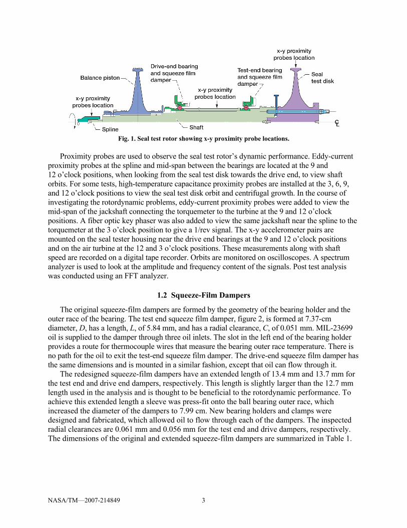
The seal test rotor, shown in figure 1, consists of a high temperature alloy shaft with two overhung disks. The test rotor is supported in two rolling element bearings. These bearings are in turn supported in squeeze film damper bearings. The 21.6-cm, overhung seal test disk is piloted into the end of the shaft and clamped in place with six studs and retaining nuts. A test end insert is clamped between the seal test disk and the shaft and provides a rotor for a single knife-edge seal, which is part of an air buffer seal that prevents hot gases from reaching the oil-lubricated bearings. A balance piston is mounted on the opposite end of the shaft and is retained by a lock washer and locknut. The split inner race angular contact ball bearings are mounted on the shaft between the two disks and separated by a bearing spacer. They are clamped in position by a shoulder on the shaft and a lock washer and locknut. The bearings are mounted in oil squeeze-film dampers. The drive end of the shaft has an external spline. The drive system consists of a 44.8 kW air turbine and a torque meter connected to each other by a jack shaft with internal straight splines at both ends. A similar jack shaft connects the torque meter to the seal test rotor. The alignment of the drive system to the seal test rotor is fixed by the housings for the jack shafts, torque meter, and turbine, which pilot to each other and pilot to the seal test rig housing.
NASA/TM—2007-214849 3
Fig. 1. Seal test rotor showing x-y proximity probe locations.
Proximity probes are used to observe the seal test rotor’s dynamic performance. Eddy-current
proximity probes at the spline and mid-span between the bearings are located at the 9 and 12 o’clock positions, when looking from the seal test disk towards the drive end, to view shaft orbits. For some tests, high-temperature capacitance proximity probes are installed at the 3, 6, 9, and 12 o’clock positions to view the seal test disk orbit and centrifugal growth. In the course of investigating the rotordynamic problems, eddy-current proximity probes were added to view the mid-span of the jackshaft connecting the torquemeter to the turbine at the 9 and 12 o’clock positions. A fiber optic key phaser was also added to view the same jackshaft near the spline to the torquemeter at the 3 o’clock position to give a 1/rev signal. The x-y accelerometer pairs are mounted on the seal tester housing near the drive end bearings at the 9 and 12 o’clock positions and on the air turbine at the 12 and 3 o’clock positions. These measurements along with shaft speed are recorded on a digital tape recorder. Orbits are monitored on oscilloscopes. A spectrum analyzer is used to look at the amplitude and frequency content of the signals. Post test analysis was conducted using an FFT analyzer.
1.2 Squeeze-Film Dampers
The original squeeze-film dampers are formed by the geometry of the bearing holder and the outer race of the bearing. The test end squeeze film damper, figure 2, is formed at 7.37-cm diameter, D, has a length, L, of 5.84 mm, and has a radial clearance, C, of 0.051 mm. MIL-23699 oil is supplied to the damper through three oil inlets. The slot in the left end of the bearing holder provides a route for thermocouple wires that measure the bearing outer race temperature. There is no path for the oil to exit the test-end squeeze film damper. The drive-end squeeze film damper has the same dimensions and is mounted in a similar fashion, except that oil can flow through it.
The redesigned squeeze-film dampers have an extended length of 13.4 mm and 13.7 mm for the test end and drive end dampers, respectively. This length is slightly larger than the 12.7 mm length used in the analysis and is thought to be beneficial to the rotordynamic performance. To achieve this extended length a sleeve was press-fit onto the ball bearing outer race, which increased the diameter of the dampers to 7.99 cm. New bearing holders and clamps were designed and fabricated, which allowed oil to flow through each of the dampers. The inspected radial clearances are 0.061 mm and 0.056 mm for the test end and drive dampers, respectively. The dimensions of the original and extended squeeze-film dampers are summarized in Table 1.

NASA/TM—2007-214849 4
Fig. 2. Test-end damper bearing.
TABLE 1.—SQUEEZE-FILM DAMPER DIMENSIONS
Squeeze film damper Diameter, cm (in.)
Length, mm (in.)
Radial clearance, mm (in.)
Original 7.37 (2.9000) 5.84 (0.230) 0.051 (0.0020) Extended, test end 7.99 (3.1452) 13.4 (0.527) 0.061 (0.0024) Extended, drive end 7.99 (3.1453) 13.7 (0.541) 0.056 (0.0022)
The damper is referred to as an un-centered squeeze-film damper since it does not have a
mechanical centering spring. The damper design is similar to that encountered in various HP aircraft gas turbine rotors. Therefore, the damper design and test results have significance towards design of damper bearings for various aircraft engine components.
The unbalance response of the seal test rotor with the rolling element bearings mounted in squeeze film dampers is highly nonlinear in nature. For the analysis of the synchronous unbalance of the test rotor, the bearing assembly is considered as a combination of the rolling element bearing in series with the un-centered, cavitated or 180°, squeeze-film damper. The damper motion consists of precession but not rotation. Since the damper aspect ratio L/D < 1, the short bearing pi film version of Reynolds equation may be applied. For the case of unbalance response, it is further assumed that the damper motion is circular synchronous precession about the bearing center. This assumption is equivalent to the assumption that the rotating load significantly exceeds the gravitational bearing loading. Under these assumptions, the nonlinear stiffness coefficient is given as follows (ref. 4):
( )( )
3
221
2, ⎟⎠⎞
⎜⎝⎛
ε−
εωμ=ωε
CLRKd (1)
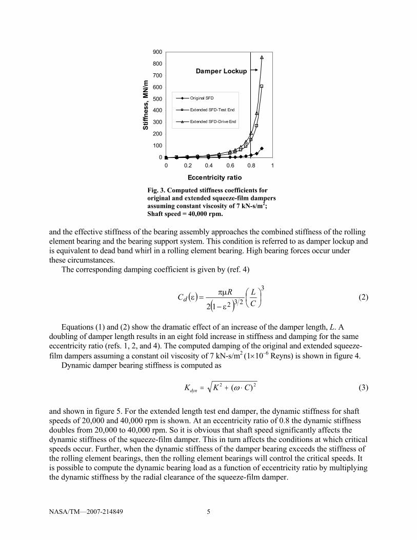
The damper radial stiffness Kd is a function of speed and eccentricity ratio. As the damper orbits outward to larger eccentricities, the damper stiffness increases. This can be seen in figure 3, which shows the computed stiffness of the original and extended squeeze-film dampers assuming a constant oil viscosity of 7 kN-s/m2 (1×10⁻⁶) Reyns. When the eccentricity ratio, the ratio of eccentricity to radial clearance of the squeeze-film damper, becomes greater than 40 percent the squeeze film damper behavior becomes non-linear. Squeeze-film damper stiffness increases rapidly at ε>0.4. At eccentricity ratios above 0.8 the radial damper stiffness becomes quite large
NASA/TM—2007-214849 5
0
100
200
300
400
500
600
700
800
900
0 0.2 0.4 0.6 0.8 1
Eccentricity ratio
Stif
fnes
s, M
N/m
Original SFD
Extended SFD-Test End
Extended SFD-Drive End
Damper Lockup
Fig. 3. Computed stiffness coefficients for original and extended squeeze-film dampers assuming constant viscosity of 7 kN-s/m2; Shaft speed = 40,000 rpm.
and the effective stiffness of the bearing assembly approaches the combined stiffness of the rolling element bearing and the bearing support system. This condition is referred to as damper lockup and is equivalent to dead band whirl in a rolling element bearing. High bearing forces occur under these circumstances.
The corresponding damping coefficient is given by (ref. 4)
( )( )
3
23212⎟⎠⎞
⎜⎝⎛
ε−
πμ=ε
CLRCd (2)
Equations (1) and (2) show the dramatic effect of an increase of the damper length, L. A
doubling of damper length results in an eight fold increase in stiffness and damping for the same eccentricity ratio (refs. 1, 2, and 4). The computed damping of the original and extended squeeze-film dampers assuming a constant oil viscosity of 7 kN-s/m2 (1×10⁻⁶ Reyns) is shown in figure 4.
Dynamic damper bearing stiffness is computed as
K K Cdyn = + ⋅2 2( )ω (3) and shown in figure 5. For the extended length test end damper, the dynamic stiffness for shaft speeds of 20,000 and 40,000 rpm is shown. At an eccentricity ratio of 0.8 the dynamic stiffness doubles from 20,000 to 40,000 rpm. So it is obvious that shaft speed significantly affects the dynamic stiffness of the squeeze-film damper. This in turn affects the conditions at which critical speeds occur. Further, when the dynamic stiffness of the damper bearing exceeds the stiffness of the rolling element bearings, then the rolling element bearings will control the critical speeds. It is possible to compute the dynamic bearing load as a function of eccentricity ratio by multiplying the dynamic stiffness by the radial clearance of the squeeze-film damper.

NASA/TM—2007-214849 6
0
10
20
30
40
50
60
70
80
90
0 0.2 0.4 0.6 0.8 1
Eccentricity ratio
Dam
ping
coe
ffici
ent,
kN-s
/m
Original SFD
Extended SFD-Test End
Extended SFD-Drive End
Damper Lockup
Fig. 4. Computed damping coefficients for original and extended squeeze-film dampers. Viscosity = 7 kN-s/m2.
0
100
200
300
400
500
600
700
800
900
0 0.2 0.4 0.6 0.8 1
Eccentricity ratio
Dyn
amic
stif
fnes
s, M
N/m
Original SFD, 40 krpm
Extended SFD-Test End,40 krpmExtended SFD-Drive End,40 krpmExtended SFD-Test End,20 krpm
Damper Lockup
Fig. 5. Computed dynamic stiffness. Viscosity =7 kN-s/m2.
2. Experimental Data
2.1 Spin Test With Original Squeeze-film Dampers
In November 2004, a spin test of the seal test rotor with the original squeeze-film damper design was conducted at room temperature conditions. No seal was installed. Shaft speed was increased in 5,000 rpm increments to 30,000 rpm. Dwell time at each speed step was approximately 5 minutes. Then speed was increased in 500 rpm increments to a maximum speed of 32,600 rpm. Then speed was reduced in approximately 5000 rpm increments with dwell times at

NASA/TM—2007-214849 7
Seal Test disk Mid-shaft Spline Jackshaft
Fig. 6. Orbits at 31,500 rpm with original squeeze-film dampers. Scale: ~ 1 mil/cm
each speed of approximately 1 minute. Shaft orbits provided the most obvious indication that a rotordynamic problem existed. Figure 6 shows the orbits at 31,500 rpm with multiple loops indicating both sub- and super-harmonic whirl at the test disk and super-synchronous response at the balance piston and drive shaft. The spline orbit is nearest the balance piston and the jackshaft orbit is in the drive system.
The recorded orbit data was played back into an ADRE system to perform an FFT analysis of the data. Since this data was recorded prior to the installation of a key phaser, the proximity probe at the 9 o’clock spline position was used to record the speed. A low-pass filter was used to remove the super-harmonic high frequency data to insure a good speed signal. Figures 7 and 8 show the waterfall plot and Bode diagram, respectively, of the proximity probe data measured at the test disk 12 o’clock location during the acceleration of the seal test rotor from 0 to 32,600 rpm.
The waterfall plot shows the amplitude and frequency content of the proximity probe signal at different shafts speeds. A high amplitude peak occurs at the frequency synchronous with the speed of rotation. Between approximately 10,000 and 15,000 rpm amplitude peaks appear at super-harmonic frequencies. At approximately 30,000 rpm amplitude peaks are excited at half the frequency of rotation indicating sub-synchronous whirl.
The corresponding Bode plot, figure 8, shows the synchronous phase lag angle and the amplitude of the direct signal and the synchronous or 1X component. The 180° drop in phase angle indicates a critical speed at approximately 21,000 rpm. The high amplitude of the direct signal between 10,000 and 15,000 rpm is super-synchronous or “dead band” whirl. Dead band whirl is very typical of squeeze-film dampers operating in their non-linear range. The sudden jump in the amplitude could represent large loads being transmitted to the rolling element bearings, which can cause distress and reduce bearing life.
Figure 9, from our previous paper (ref. 7), shows the seal test rig synchronous x and y accelerometer amplitude versus speed to 34,000 rpm. An apparent vertical (y) resonant mode is observed at 20,000 rpm. A much stronger resonant mode for the horizontal (x) accelerometer occurs at 32,000 rpm. The difference between the vertical and horizontal accelerometer readings is due to the differences in bearing and support horizontal and vertical stiffness and damping values for the two planes. This asymmetric effect is often observed in un-centered dampers with moderate unbalance.

NASA/TM—2007-214849 8

NASA/TM—2007-214849 9
Test Disk Mid-shaft Spline Jackshaft
Fig. 10. Seal test rotor orbits at 40,444 rpm with extended squeeze-film dampers. Scale: ~1 mil/cm.
2.2 Hot Spin Test With Extended Squeeze-Film Dampers
The hot spin test was conducted in November 2006 with the extended squeeze-film dampers installed. Due to a mishap, the spare shaft had to be used. All other components are the same. The balance of the assembly was checked and corrected as needed. A worn brush seal was installed at the test disk to allow functional verification of the balance piston to manage the axial thrust loads. Inlet air temperature to the test seal was 538 to 693 °C (1000 to 1100 °F). Figure 10 shows the seal test rotor orbits at 40,444 rpm. Motion at the test disk is small, approximately 0.0254 mm (0.001 in.).
The waterfall plot and Bode plot of the proximity probe data measured at the test disk 12 o’clock location during the acceleration of the seal test rotor from 0 to 40,444 rpm are shown in figures 11 and 12, respectively. The waterfall plot shows peak amplitudes at the frequency of rotation with small peaks at 2 times the frequency of rotation. The Bode plot shows small amplitudes. It does not show more than a 90° phase change over entire speed range, which is somewhat surprising. A 180° phase change is expected as the seal test rotor passes through each critical speed.
Fig. 9. x-y seal rig synchronous accelerometer amplitudes versus speed.

NASA/TM—2007-214849 10
A single-channel spectrum analyzer was used to measure the synchronous peak amplitudes of
the proximity probe at the seal test disk at each steady speed level as shown in figure 13. The test disk 12 o’clock probe data shows critical speeds at approximately 20,000 and 30,000 rpm. The 9 o’clock probe confirms a critical speed at approximately 30,000 rpm. It also appears some transition occurs around 5,000 rpm.

NASA/TM—2007-214849 11
3. Critical Speed Analysis
3.1 Critical Speed Analysis of Test Rig Including Drive System
In our previous paper (ref. 7) DyRoBes, a commercially available rotordynamic analysis package (ref. 3), was used to model and analyze the seal test rotor and its drive system to assess the possible source of and solution to the vibration problem in the seal rig. In this study the system critical speed analysis predicted first and second critical speeds at 21,113 and 33,500 rpm, respectively, which closely match the X-Y rig synchronous accelerometer data. The first and second critical speeds excited conical and bending modes, respectively, in the seal test rotor, but the drive system was relatively quiet and not a contributor to the vibration problem. Hence, the drive system could be omitted from further analysis (ref. 7).
3.2 Critical Speed Analysis of Seal Test Rotor
Figure 14 is a model of the seal test rotor. The un-centered squeeze film dampers used to support the ball bearings are highly nonlinear. However, it is still of value to evaluate the rotor undamped critical speeds in order to determine the rotor mode shapes and the corresponding energy distribution for each mode.
From our previous paper (ref. 7), constructing an undamped critical speed map (fig. 15) of the seal test rotor bounded the bearing stiffness between 175 and 298 MN/m. Further, the first mode potential energy distribution showed that two plane balancing is sufficient and that the test-end bearing controls sub-synchronous whirling. Second mode potential energy distribution indicated that the drive-end bearing controls the second critical speed. Figure 16 shows the first mode is essentially a conical rigid body mode with the seal test disk and the balance piston out of phase.
Figure 17 represents the second critical speed mode shape at 31,291 rpm for an assumed bearing stiffness of 175 MN/m. The second critical speed is a bending mode.

NASA/TM—2007-214849 12
Fig. 14. Model of seal test rotor with squeeze film dampers.
4. Dynamic Analysis
4.1 Original Squeeze-film Dampers
Nonlinear synchronous unbalance response analysis of the seal test rotor with the original damper bearing length of 5.84 mm and an unbalance at the seal test disk of 0.360 kg-mm showed high shaft displacements at speeds above 33,000 rpm which could damage the rotor. Examination of the mode shape indicates that the original damper bearings bottom out or “lock up” at 33,000 rpm. The time transient analysis of the seal test rotor with the original dampers indicated that the seal test rotor is sensitive to small cross coupling forces that could be generated in typical seals and that the maximum seal test disk orbit could exceed 0.2 mm if it had an unbalance of 0.360 kg-mm (ref. 7).
4.2 Extended Squeeze-Film Dampers
The synchronous unbalance response of the seal test rotor with increased squeeze film damper lengths of 12.7 mm and limiting the unbalance to 0.072 kg-mm at both the seal test disk and balance piston at 90° out of phase shows smooth rotor response to 50,000 rpm with little shaft bending. Figure 18 shows the transient response of the seal test rotor at 35,000 rpm with two planes of unbalance and aerodynamic cross-coupling. The aerodynamic cross-coupling simulates sealing loads on the test disk. Note the conical shaft motion with active damper motion. There is no indication of self excited whirl motion present in the transient analysis. Figure 19 represents the transient motion at 45,000 rpm. The motion is stable limit cycle whirl.
Fig. 16. First mode shape at 20,088 rpm with Kb= 175 MN/m.
Fig. 17. Second mode shape at 31,291 rpm with Kb = 175 MN/m.
Fig. 15. Critical speed map of seal test rotor with Linear bearings.

NASA/TM—2007-214849 13
Fig. 18. Transient seal test rotor motion at 35,000 rpm with enhanced squeeze-film dampers, L=12.7mm, Ub=0.072 kg-mm at balance piston and seal test disk, Q=876 kN-m.
Fig. 19. Transient motion at 45,000 rpm showing stable limit cycle whirl motion with enhanced damper, L=12.7 mm.
If the two plane unbalance is increased to 0.360 kg-mm then the transient response analysis
showed damper lockup at 33,600 rpm. Hence, analysis showed that the seal test rotor can be successfully operated to its maximum design speed of 43,140 rpm if the squeeze film damper lengths are extended to 12.7 mm and the seal test rotor is well balanced (ref. 7).
Discussion and Conclusions The extended squeeze-film dampers allowed the seal test rotor to be successfully operated
to 40,444 rpm, the desired maximum operating speed. Further, with the original undersized squeeze-film dampers there was risk of going into super-synchronous or deadband whirl, which can transmit excessive loads to the ball bearings and reduce their life. Improvements to the rotor balance would not reduce this risk. In fact, running with an unbalance might actually make the rotor whirl in the dampers, which is better than overloading the ball bearings. However, with the original length squeeze-film dampers the maximum operating speed could not be obtained.

NASA/TM—2007-214849 14
The initial design of squeeze-film dampers for high-speed rotors is difficult due to the nonlinear characteristics of the damper stiffness and damping. Rotordynamic analysis provided insight to the seal test rotor transient and dynamic behavior, predicted critical speeds in good agreement with experimental data, and proved to be a useful tool in determining how to improve the rotordynamic performance of the seal test rotor. Waterfall and Bode plots generated by FFT analysis of the experimental data revealed deadband whirl with the original dampers, which was missed during initial data analysis. Deadband whirl appears in these plots as a nonlinear jump region in which super-synchronous vibrations of the rotor occur. Deadband whirl can occur with any rolling element bearing system with clearance space. Conducting FFT analysis over the entire speed range and generating the waterfall plots of amplitude versus frequency and reviewing Bode plots is recommended to diagnose and understand a system’s rotordynamic behavior.
The length of the original squeeze-film damper was slightly more than doubled. Based on short bearing theory, this yields an eightfold increase in both stiffness and damping for a given whirl eccentricity. With the new damper design, whirl instability observed at the seal rotor test disk was removed along with the dead band whirl region and the high synchronous unbalance response. Theoretically, with sufficient rotor unbalance, nonlinear damper lock-up can also occur with the new damper design. The problem of squeeze-film damper lockup in a high-speed rotor system can be alleviated by proper damper support structure design. Redesigning the damper supports to alleviate damper lockup remains a subject for a future paper.
References 1. Barrett, L.E., and Gunter, E.J., Steady State and Transient Analysis of a Squeeze Film
Damper Bearing for Rotor Stability, NASA CR–2548, (1975). 2. Gunter, E.J., Barrett, L.E., Allaire, P.E., Design of Nonlinear Squeeze Film Dampers For
Aircraft Engines, ASME Journal of Lubrication, Vol. 92, No. 1 (1977) 57–64. 3. Chen, W.J., and Gunter, E.J., DyRoBes Reference Manual on Rotor Bearing Dynamics,
version 9, RODYN Vibration Analysis, Inc., Charlottesville, VA, 22903 (2004). 4. Chen, W.J., and Gunter, E.J., Introduction to Dynamics of Rotor-Bearing Systems, Trafford
Publishing, Victoria, B.C., Canada, (2005). 5. Proctor, M.P., Kumar, A., and Delgado, I.R., High-Speed, High-Temperature Finger Seal
Test Results, Journal of Propulsion and Power AIAA, Vol. 20, No. 2, (2004) 312–318. 6. Proctor, M.P., and Delgado, I.R., Leakage and Power Loss Test Results for Competing
Turbine Engine Seals, NASA/TM—2004-213049, ARL–TR–3157, GT2004–53935, (2004). 7. Proctor, M.P., and Gunter, E.J., Nonlinear Whirl Response of a High-Speed Seal Test Rotor
With Marginal and Extended Squeeze-Film Dampers, NASA/TM—2005-213808, ISCORMA-3 Paper No. 212, Cleveland, OH, (2005).

REPORT DOCUMENTATION PAGE Form Approved OMB No. 0704-0188
The public reporting burden for this collection of information is estimated to average 1 hour per response, including the time for reviewing instructions, searching existing data sources, gathering and maintaining the data needed, and completing and reviewing the collection of information. Send comments regarding this burden estimate or any other aspect of this collection of information, including suggestions for reducing this burden, to Department of Defense, Washington Headquarters Services, Directorate for Information Operations and Reports (0704-0188), 1215 Jefferson Davis Highway, Suite 1204, Arlington, VA 22202-4302. Respondents should be aware that notwithstanding any other provision of law, no person shall be subject to any penalty for failing to comply with a collection of information if it does not display a currently valid OMB control number. PLEASE DO NOT RETURN YOUR FORM TO THE ABOVE ADDRESS. 1. REPORT DATE (DD-MM-YYYY) 17-07-2007
2. REPORT TYPE Technical Memorandum
3. DATES COVERED (From - To)
4. TITLE AND SUBTITLE Stability Analysis of a High-Speed Seal Test Rotor With Marginal and Extended Squeeze-Film Dampers--Theoretical and Experimental Results
5a. CONTRACT NUMBER
5b. GRANT NUMBER
5c. PROGRAM ELEMENT NUMBER
6. AUTHOR(S) Proctor, Margaret, P.; Gunter, Edgar, J.
5d. PROJECT NUMBER
5e. TASK NUMBER
5f. WORK UNIT NUMBER WBS 561581.02.08.03.15.02
7. PERFORMING ORGANIZATION NAME(S) AND ADDRESS(ES) National Aeronautics and Space Administration John H. Glenn Research Center at Lewis Field Cleveland, Ohio 44135-3191
8. PERFORMING ORGANIZATION REPORT NUMBER E-16048-1
9. SPONSORING/MONITORING AGENCY NAME(S) AND ADDRESS(ES) National Aeronautics and Space Administration Washington, DC 20546-0001
10. SPONSORING/MONITORS ACRONYM(S) NASA
11. SPONSORING/MONITORING REPORT NUMBER NASA/TM-2007-214849
12. DISTRIBUTION/AVAILABILITY STATEMENT Unclassified-Unlimited Subject Category: 37 Available electronically at http://gltrs.grc.nasa.gov This publication is available from the NASA Center for AeroSpace Information, 301-621-0390
13. SUPPLEMENTARY NOTES
14. ABSTRACT A case study of a high-speed seal test rotor shows how rotor dynamic analysis can be used to diagnose the source of high vibrations and evaluate a proposed remedy. Experimental results are compared with the synchronous and non-synchronous whirl response analysis of a double overhung, high-speed seal test rotor with ball bearings supported in 5.84- and 12.7-mm-long, un-centered squeeze-film oil dampers. Test performance with the original damper of length 5.84 mm was marginal. Non-synchronous whirling occurred at the overhung seal test disk and there was a high amplitude synchronous response near the drive spline above 32,000 rpm. Nonlinear synchronous unbalance and time transient whirl studies were conducted on the seal test rotor with the original and extended damper lengths. With the original damper design, the nonlinear synchronous response showed that unbalance could cause damper lockup at 33,000 rpm. Alford cross-coupling forces were also included at the overhung seal test disk for the whirl analysis. Sub-synchronous whirling at the seal test disk was observed in the nonlinear time transient analysis. With the extended damper length of 12.7 mm, the sub-synchronous motion was eliminated and the rotor unbalance response was acceptable to 45,000 rpm with moderate rotor unbalance. Seal test rotor orbits and vibration levels with the extended squeeze film dampers showed smooth operation to 40,444 rpm. 15. SUBJECT TERMS Nonlinear whirl response; Squeeze-film dampers; Damper lockup; Rotordynamics
16. SECURITY CLASSIFICATION OF: 17. LIMITATION OF ABSTRACT
18. NUMBER OF PAGES
20
19a. NAME OF RESPONSIBLE PERSON Margaret P. Proctor
a. REPORT U
b. ABSTRACT U
c. THIS PAGE U
19b. TELEPHONE NUMBER (include area code) 216-977-7526
Standard Form 298 (Rev. 8-98)Prescribed by ANSI Std. Z39-18