stackup planning pt1 pcbd-june2015 - icd · in the ‘u’ bend coupling the signal many ... are...
TRANSCRIPT

16
S U M M A R Y
CO
LU
MN
For source-synchronous interfaces such as DDR memory, the data signals must arrive at the load at the same time as the clock or data strobe. This is done, for instance, by matching the lengths of all the signals between data lanes and strobes within a certain tolerance. For DDR2, this is 50 MIL within data lanes including the strobe. Address and command signals are not as critical with a tolerance of 200 MIL. However, matching the lengths does not mean that the propagation delay for each signal will be the same. Also, traces routed to length on different layers exhibit different delays and this is most evident when comparing microstrip (outer layers) to stripline
(inner layers) and is due to the difference in dielectric materials surrounding the traces.
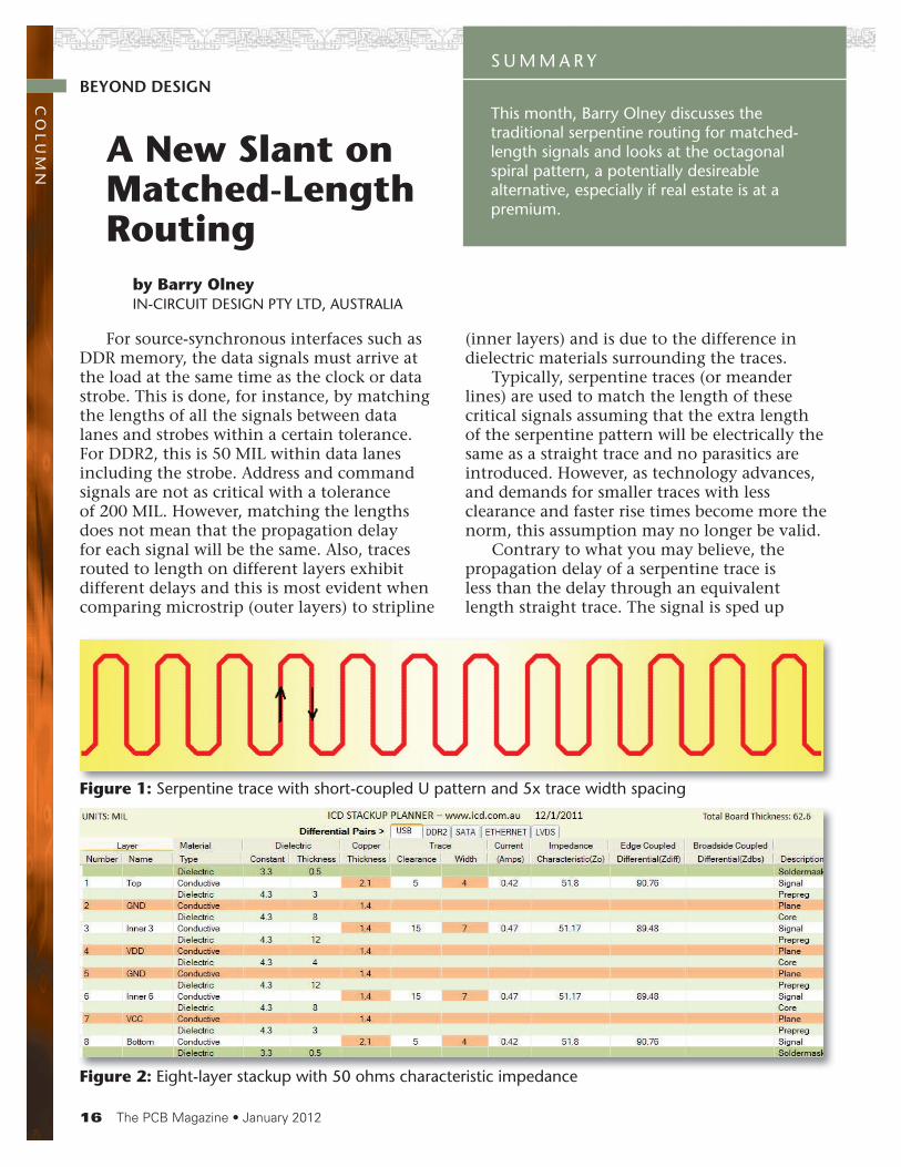
Typically, serpentine traces (or meander lines) are used to match the length of these critical signals assuming that the extra length of the serpentine pattern will be electrically the same as a straight trace and no parasitics are introduced. However, as technology advances, and demands for smaller traces with less clearance and faster rise times become more the norm, this assumption may no longer be valid.
Contrary to what you may believe, the propagation delay of a serpentine trace is less than the delay through an equivalent length straight trace. The signal is sped up
This month, Barry Olney discusses the traditional serpentine routing for matched- length signals and looks at the octagonal spiral pattern, a potentially desireable alternative, especially if real estate is at a premium.
A New Slant on Matched-Length Routing
by Barry Olney IN-CIRCUIT DESIGN PTY LTD, AUSTRALIA
BEYOND DESIGN
Figure 1: Serpentine trace with short-coupled U pattern and 5x trace width spacing
Figure 2: Eight-layer stackup with 50 ohms characteristic impedance

18
because a portion of the signal will propagate perpendicular to the serpentine. And, this also varies with the type of serpentine pattern used. For example, the serpentine pattern may have long parallel lengths spaced close together in the ‘U’ bend coupling the signal many times through the serpentine pattern. This self-coupling (forward and reverse crosstalk) shortens the electrical path.
Let’s have a look at the effects of altering the patterns. First, we must build the stackup so that we have 50 ohms characteristic impedance on all signals so that we can compare apples to apples. Figure 2 was built with the ICD Stackup Planner (download from www.icd.com.au).
I first created a layout, placed three drivers and loads, then routed three different microstrip trace patterns with identical lengths and series terminators (Figure 2a).
All traces have the same attributes:
Driver: CMOS, 3.3V, 300pS *Trace length: 12000 +/- 10 MIL *Trace width: 4 MILImpedance: ~ 50 ohmSeries Terminator: 43.8 ohm
As you can see, there is crosstalk between each segment of the closely coupled serpentine trace. The coupled region is actually the entire length of the serpentine trace although the
1. Straight trace 12 inch (reference trace)
2. Serpentine trace with close coupling
3. Serpentine trace with 5 x trace width spacing
Figure 2a.
Figure 3: Serpentine trace with close coupling.
A NEW SLANT ON MATCHED-LENGTH ROUTING continues

19
software only displays the first few segments.* This model and trace length were chosen
to enable comparison to Howard Johnson’s simulations 4
We can see from Figures 4 and 5 that the 5x trace width spacing serpentine trace has less noise and the delay matches the straight reference trace very closely.
For decades, RF engineers have been using printed circuit coils to create specialized inductors in their designs. Inductors may be etched directly into the PCB by laying out the trace in a spiral pattern. Some of these patterns are quite complex and are best left to the experts as many consider this a black art. In
1928, Wheeler first developed an equation to calculate the inductance of a planar octagonal spiral coil inductor.
Figure 4: Closely-coupled serpentine trace vs. straight trace (microstrip)
Figure 5. Serpentine trace with 5x trace spacing vs. straight trace (microstrip)
A NEW SLANT ON MATCHED-LENGTH ROUTING continues
Green is driver Red is straight (reference) trace.Blue is the closely coupled serpentine trace which leads the reference trace by 150 pS. The peaks in the blue serpentine trace (from 4 to 6nS) are the reverse and forward cross-talk respectively from the close coupling.
Green is driver Red is straight (reference) trace.Blue is the 5 x trace width spacing serpentine trace which leads the reference trace by 15 pS. The peak in the blue serpentine trace (around 5nS) is the forward crosstalk.
where n = number of turns a = (Diameter max + Diameter min)/4 c = (Diameter max - Diameter min)/2

20
A NEW SLANT ON MATCHED-LENGTH ROUTING continues
The serpentine pattern was replaced by the octagonal spiral inductor in Figure 6. A trace was routed from the driver, through the series terminator, then to a via at the centre of the spiral. The pattern then spirals out using a 4-MIL trace with 4-MIL spacing to give 10.25 turns. Using Wheeler’s equation above, the inductance is calculated at ~ 3nH.
Notice that the current flow in the coil is in the same direction. Therefore, there is no reverse crosstalk, but only forward crosstalk.
The coupled region is actually the entire spiral although the software only displays the first few segments. It is difficult to route with modern shape-based interactive routers
as the trace tends to clean up behind the cursor, eliminating the spiral. With all glossing and post-route clean-up turned off, it can be completed quite quickly. The nice thing about the spiral pattern is that it is very compact.
Let’s compare this to that of the serpentine trace, first simulating it on the outer (microstrip) layers.
Serpentine (blue) leads the straight reference trace (red) by 150 pS. Spiral (violet) is leading the reference trace by 22 pS.
As can be expected, the octagonal spiral inductor has a huge 500-mV peak from the effects of forward crosstalk. No reverse crosstalk is present.
Figure 7: Octagonal spiral inductor forward crosstalk (microstrip)Fi 7
Figure 8: Octagonal spiral inductor (violet) vs. the closely coupled serpentine trace (blue) – (microstrip)
Figure 6: Planar octagonal spiral coil inductor.

21
A NEW SLANT ON MATCHED-LENGTH ROUTING continues
In this case, the spiral’s delay is much less than the closely coupled serpentine trace. Since we would not normally have 12 inches of trace on a high-speed design, we can divide this by 6 to give us approximately 2 inches of length, which is more the norm. Therefore, the serpentine trace will be leading the straight reference trace by 25 pS and the spiral will be
just 3.6 pS ahead of the reference trace. But, crosstalk has dramatically increased.
In theory, the forward crosstalk or far end crosstalk does not exist in the stripline configuration. So let’s see how the spiral performs embedded between the planes in a stripline construction (Figure 9).
The straight reference trace (red), the
Figure 9: Serpentine (with 5x trace width spacing) vs. spiral pattern (stripline)
Figure 10: (left) EMI from the serpentine pattern (microstrip) 51.54 dB @ 952 MHz and 50.82 dB @ 4.76 GHz, (right) EMI from the spiral pattern (microstrip) 50.54 dB @ 952 MHz and 37.63 dB @ 4.24 GHz

22
serpentine with 5x spacing (blue) and the spiral (violet) are now routed on layer 3 (stripline) and the forward crosstalk is eliminated as predicted. The spiral trace now leads the straight trace by ~ 60 pS and the serpentine lags by 10 pS. Dividing the results again by 6 (to bring us back to the real world) gives the relative delay at 2 inches: Spiral leads the straight line by 10 pS and the serpentine lags by 1.66 pS. So, with the negligible 10-pS lead, the spiral pattern has potential as an alternative to serpentine routing.
Normally, one would be concerned about a crosstalk level of 500 mV, which was exhibited on the microstrip spiral pattern (Figure 8), as it may well exceed the noise margin. But is this really crosstalk? Crosstalk is the unintentional electromagnetic coupling between traces on a PCB — normally between two or more different signals where one is an aggressor that
imposes noise on the victims. But in this case, we have the same signal imposing noise on itself. So the peak that we have called forward crosstalk is actually just overshoot of 500 mV at the top on the rising edge. This overshoot does not affect timing and has little effect on the signal integrity. But does it create radiation (EMI)?
For the stripline configurations, where the waveforms are almost identical for both serpentine and spiral patterns, the EMI is also identical. But for microstrip configurations, the radiation is quite different. One would not normally route 12-inch traces, as previously stated on high-speed designs, so we can expect the level to be high in both cases.
It is interesting to note in Figure 10 that the radiation level below 3-GHz peaks at exactly the same frequency (51 dB @ 952 MHz) for both the serpentine and spiral, which is the 7th harmonic. However, at higher frequencies the radiation rolls off for the spiral pattern emitting 13 dB less radiation, with fewer harmonics, around 5 GHz. This is interesting because one would expect this to be the opposite since overshoot or ringing is generally a source of radiation.
The serpentine pattern on the microstrip layer acts as an antenna emitting radiation from the ends of the ‘U’ bends. A Meander-line Antenna (MLA) is a type of microstrip antenna first developed in 1953, but recently become very popular in mobile devices as it is extremely compact, low profile and easy to fabricate. The MLA can be a half wavelength dipole or a quarter wavelength ground plane format.
One can see (Fig. 11) the large magnitude of current on the end sections of the meander-
Figure 11: Current magnitude of a microstrip meander-line antenna 7 — meander trace (left) and the ground plane (right)
Figure 12: Area of the serpentine pattern (with 5x trace width spacing) vs. spiral pattern.
A NEW SLANT ON MATCHED-LENGTH ROUTING continues

23
VID
EO
INT
ER
VIE
W
Editor Ray Rasmussen sat down recently with Dr. Markus Riester of maris TechCon, who discusses some of the issues he addressed during a panel session on reliability in medical electronics at productronica 2011.
Reliability in Medical Electronicsby Real Time with...productronica 2011
Barry Olney is Managing Director of In-Circuit Design Pty Ltd. (ICD), Australia, a PCB Design Service Bureau and Board Level Simulation Specialist. Among others through the years, ICD was awarded “Top 2005 Asian Distributor Marketing and “Top 2005 Worldwide Distributor Marketing by
Mentor Graphics, Board System Division. For more information, contact Barry Olney at +61 4123 14441 or email at [email protected].
ofAuanAm
Wo
line. These are essentially the only source of radiation — the wave resonates between the microstrip antenna and the ground plane. The serpentine pattern may not be an efficient antenna but nevertheless is acting as a 50-ohm antenna, as the harmonics approach a multiple of a quarter wavelength, since it is driving a high impedance load.
In conclusion, serpentine traces are commonly used for matched length signals and supported by all popular EDA tools. It is therefore easier to follow tradition and use this pattern. It would be best using the serpentine pattern with at least 5x trace width spacing in a stripline configuration to reduce crosstalk and radiation.
However, as technology advances and demands for thinner traces with less clearance and faster rise times become more the norm, one may have to look at alternatives. As you can see from Figure 12 below, the octagonal spiral pattern takes up less than ¼ of the space (area) of the serpentine pattern. So, if real estate is at a premium then maybe it’s time to give the old spiral a go. PCB
References1. PCB Design Techniques for DDR, DDR2 &
DDR3 — Barry Olney2. Advanced Design for SMT — Barry Olney3. Design for EMC — Barry Olney4. High-Speed Signal Propagation, Advanced
Black Magic – Howard Johnson5. Method for Compressing Serpentine Trace
Routing on Printed Circuit Boards – Bogusch, Ernest B
6. Transmission Line Design Handbook – Wadell
7. The Study and Implementation of Meander-line Antenna for an Integrated Transceiver Design — MinJie Ma, Kai Deng
8. The ICD Stackup Planner can be downloaded from www.icd.com.au
realtimewith.com