staff.iha.dkstaff.iha.dk/lc/steel/samlet_plate_beams.docx · web view8 lateral torsional buckling...
TRANSCRIPT
Plated structural elements Case Study svenebbe
Filnavn: H:\public_html\Steel\Samlet
Forside
Table of Contents1 Description...............................................................................................................................................4
1.1 Building and structure.......................................................................................................................4
Figure 1. The building as axonometric view.........................................................................................4
2 Geometri..................................................................................................................................................4
Figure 2.1. Ceiling plane.......................................................................................................................4
Figure 2.2. Elevation of plated frame...................................................................................................5
Figure 2.2. Elevation of tapered frame................................................................................................5
Figure 2.4. Elevation of frame model...................................................................................................6
3 Loads........................................................................................................................................................6
3.1 Dead load...........................................................................................................................................6
3.2 Snow..................................................................................................................................................6
3.3 Wind..................................................................................................................................................6
4 Forces.......................................................................................................................................................9
Figure 4.1. Moment forces in unicross frame......................................................................................9
Figure 4.2. Moment.............................................................................................................................9
Figure 4.3. Shear Forces.....................................................................................................................10
Figure 4.4. Normal Forces..................................................................................................................10
5 Example..............................................................................................................................................11
Figure 1..............................................................................................................................................11
5.1 Cross sections..................................................................................................................................11
5.2 Normal stress...................................................................................................................................12
5.3 Section classes.................................................................................................................................12
5.4 Effective cross-section.....................................................................................................................12
5.5 Bending resistance...........................................................................................................................13
5.6 Normal stress Diagrams...................................................................................................................14
6 Shear resistance..................................................................................................................................14
1

Plated structural elements Case Study svenebbe
6.2 Contribution from the web..............................................................................................................15
Shear buckling coefficients....................................................................................................................16
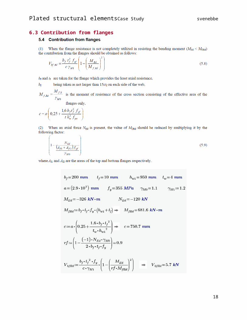
6.3 Contribution from flanges...................................................................................................................16
7 Lateral torsional buckling....................................................................................................................17
Torsion constant................................................................................................................................17
Warping constant..............................................................................................................................17
Critical moment.................................................................................................................................18
Interaction between shear force, bending moment and axial force......................................................18
Flange induced buckling........................................................................................................................18
Critical plate buckling stress for plates with one or two stiffeners in the..............................................18
compression zone..................................................................................................................................18
Plastic analysis of beam.........................................................................................................................18
Framed knee..........................................................................................................................................18
Support..................................................................................................................................................18
Finite Element Methods of analysis (FEM)............................................................................................18
Frame model.....................................................................................................................................18
Plate model........................................................................................................................................18
2
Plated structural elements Case Study svenebbe
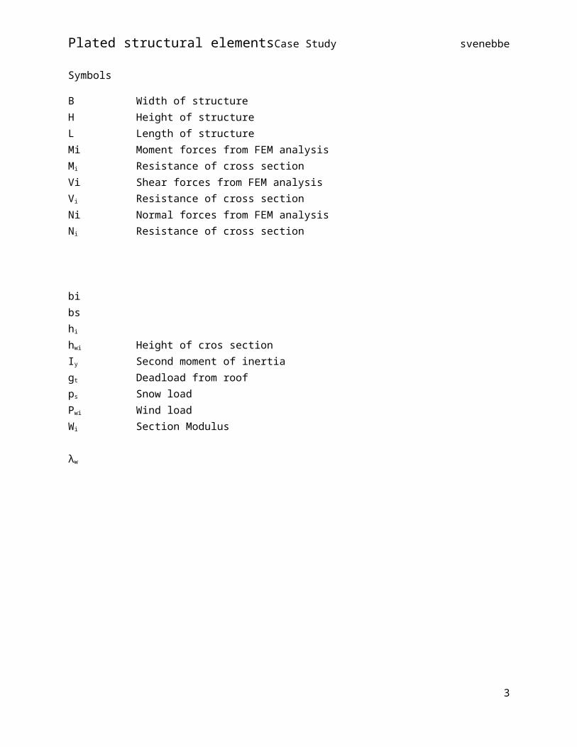
Symbols
B Width of structureH Height of structureL Length of structureMi Moment forces from FEM analysisMi Resistance of cross sectionVi Shear forces from FEM analysisVi Resistance of cross sectionNi Normal forces from FEM analysisNi Resistance of cross section
bibshi
hwi Height of cros sectionIy Second moment of inertiagt Deadload from roofps Snow loadPwi Wind loadWi Section Modulus
λw
3
Plated structural elements Case Study svenebbe
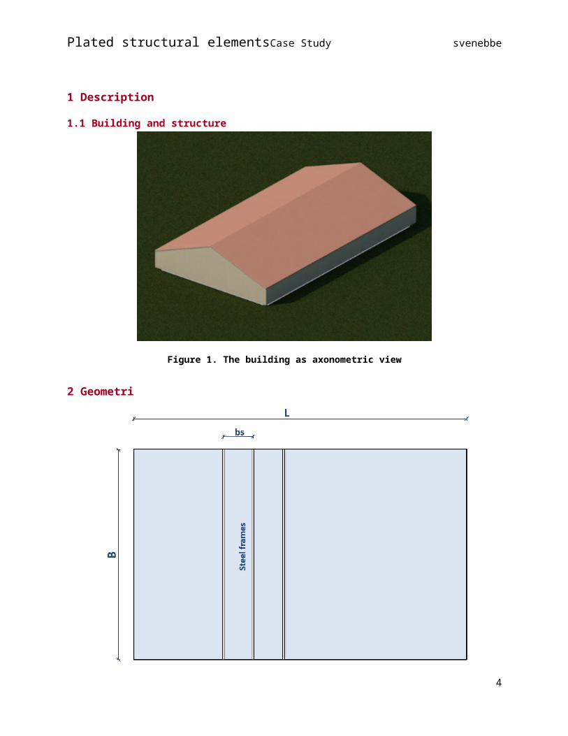
1 Description
1.1 Building and structure
Figure 1. The building as axonometric view
2 Geometri
4

Plated structural elements Case Study svenebbe
Figure 2.1. Ceiling plane
5
Plated structural elements Case Study svenebbe
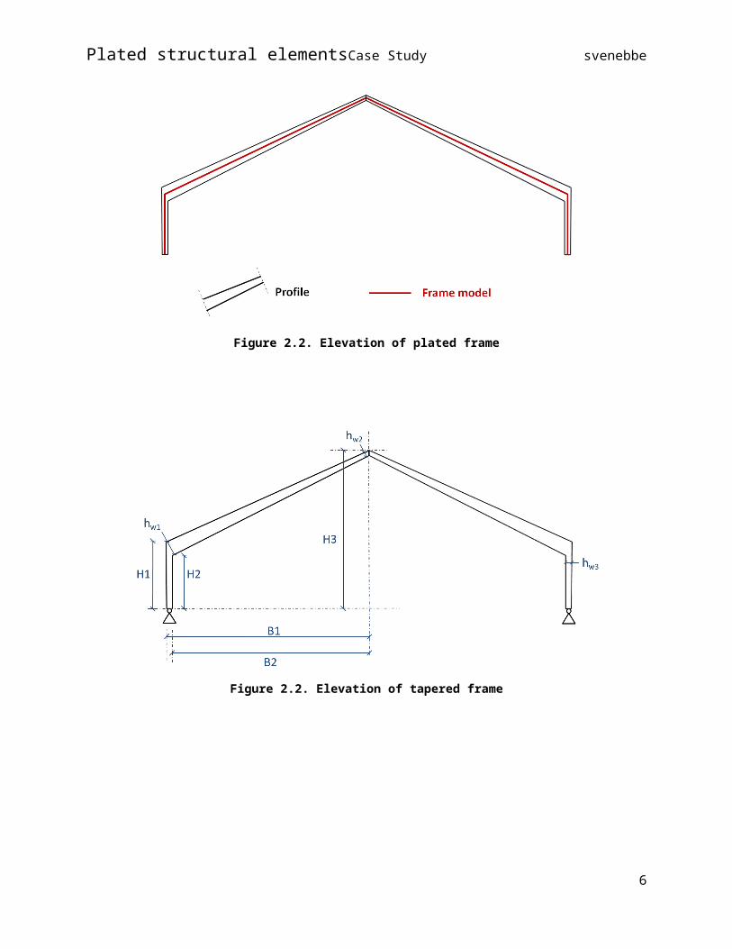
Figure 2.2. Elevation of plated frame
Figure 2.2. Elevation of tapered frame
6
Plated structural elements Case Study svenebbe
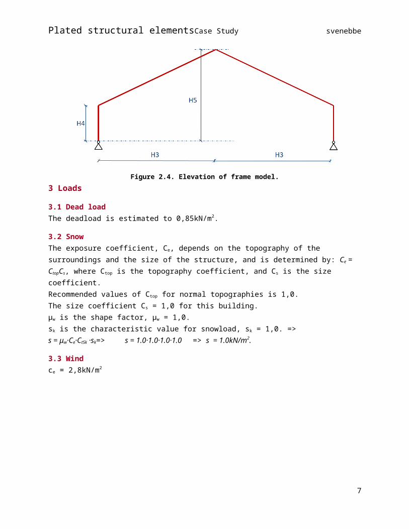
Figure 2.4. Elevation of frame model.
3 Loads
3.1 Dead loadThe deadload is estimated to 0,85kN/m2.
3.2 SnowThe exposure coefficient, Ce, depends on the topography of the surroundings and the size of the structure, and is determined by: Ce = CtopCs, where Ctop is the topography coefficient, and Cs is the size coefficient.Recommended values of Ctop for normal topographies is 1,0. The size coefficient Cs = 1,0 for this building.μw is the shape factor, μw = 1,0.sk is the characteristic value for snowload, sk = 1,0. =>s = μw·Ce·CtSk ·sk=> s = 1.0·1.0·1.0·1.0 => s = 1.0kN/m2.
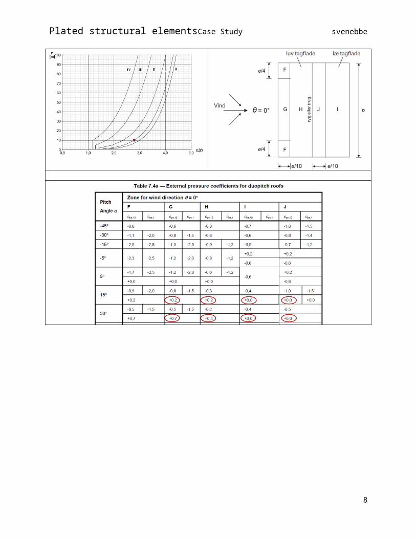
3.3 Windce = 2,8kN/m2
7
Plated structural elements Case Study svenebbe
8
Plated structural elements Case Study svenebbe
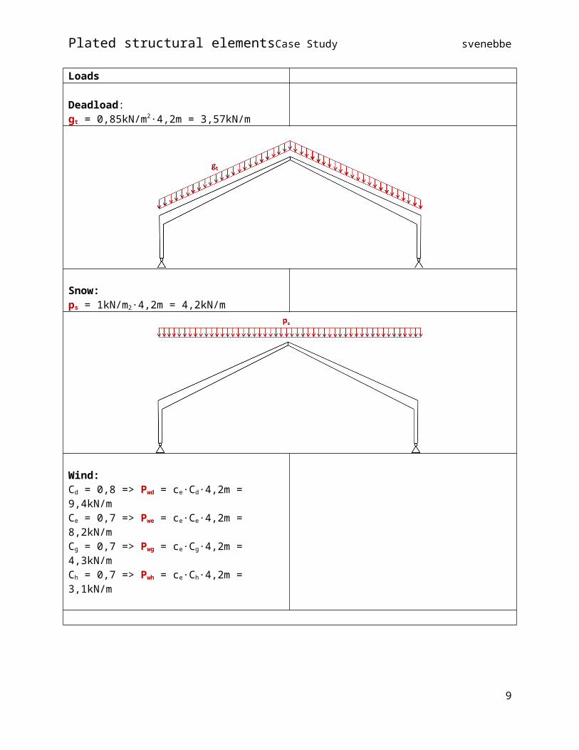
Loads
Deadload:gt = 0,85kN/m2·4,2m = 3,57kN/m
Snow:ps = 1kN/m2·4,2m = 4,2kN/m
Wind:Cd = 0,8 => Pwd = ce·Cd·4,2m = 9,4kN/mCe = 0,7 => Pwe = ce·Ce·4,2m = 8,2kN/mCg = 0,7 => Pwg = ce·Cg·4,2m = 4,3kN/mCh = 0,7 => Pwh = ce·Ch·4,2m = 3,1kN/m
9

Plated structural elements Case Study svenebbe
4 ForcesThe effect of the tapered section is determined:
Figure 4.1. Moment forces in unicross frame
Figure 4.2. Moment
10

Plated structural elements Case Study svenebbe
Figure 4.3. Shear Forces
Figure 4.4. Normal Forces
11

Plated structural elements Case Study svenebbe
5 Example
Figure 1
5.1 Cross sections hw2 = 380mm hw1 = 950mm
12
Plated structural elements Case Study svenebbe
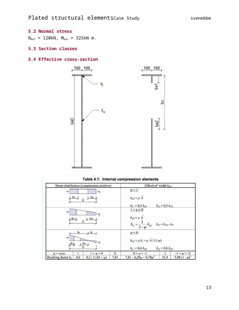
5.2 Normal stressNmin = 120kN, Mmin = 325kN·m.
5.3 Section classes
5.4 Effective cross-section
13

Plated structural elements Case Study svenebbe
hw1=950mm, tw=4mm
f y=355MPa Nmin=−120 kNMmin=−326 kNm
σ N=N min
AσM=
Mmin
W y
σ 1=σ N+σM
σ 2=σ N−σM
bc=hw 1 ·σ1
σ1−σ2Ψ=
σ2σ1
k σ=7,81−6,29 ·Ψ+9,78·Ψ 2
λw=hw 1
28,4 ·tw ·√ 235f y·√kσ
beff=ρ· bc
be1= ρ·beffbe2=ρ·beff
bh=ρ·(bc−(be1−be 2))
Sw=−bh ·tw ·(hw 1
2−be 1−
bh
2)
ρ=(λw−0,055 · (3+Ψ ))
λw2
5.5 Bending resistance
Cross section Section modulus Moment capacityPlastic 2,8·106·mm3 MpRd = 911·kNmElastic 2,4·106·mm3 MeRd = 785·kNmEffective 2,1·106·mm3 MefRd = 662·kNmFlanges only 1,9·106·mm3 MflRd = 620·kNm
14

Plated structural elements Case Study svenebbe
5.6 Normal stress Diagrams
15
Plated structural elements Case Study svenebbe
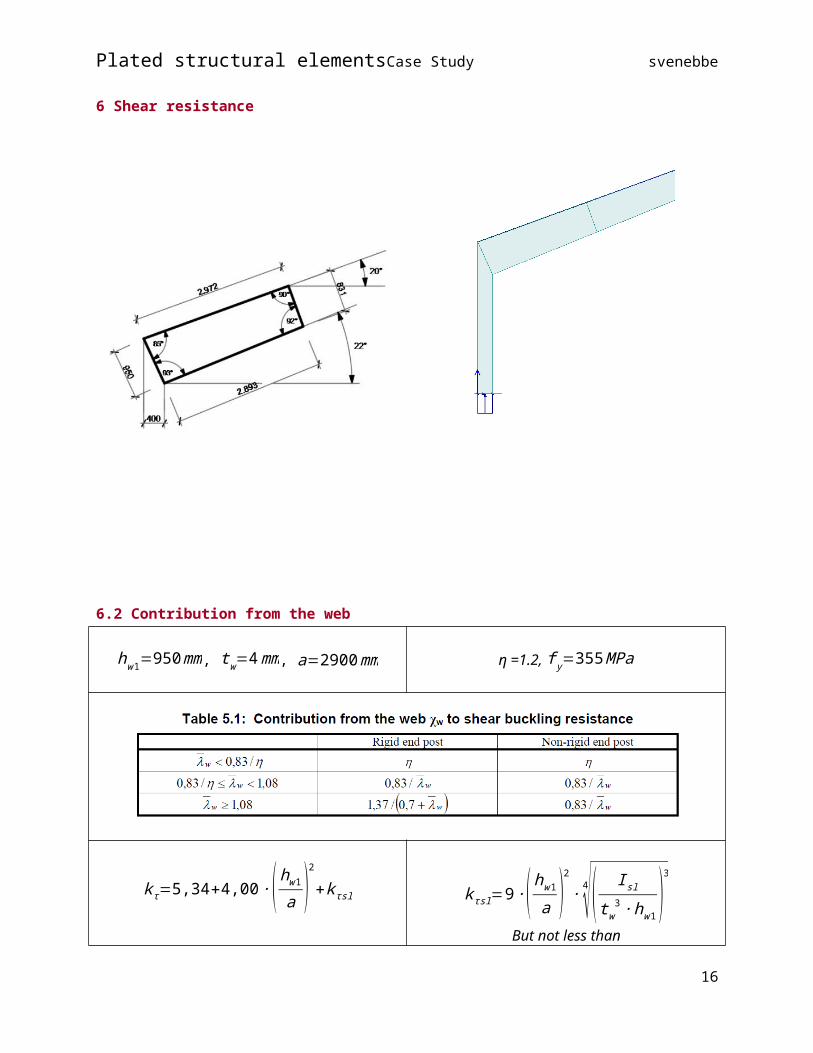
6 Shear resistance
6.2 Contribution from the web
hw1=950mm, tw=4mm, a=2900mm η =1.2, f y=355MPa
k τ=5,34+4,00 ·( hw 1a )2
+k τsl
ahw 1
>1
k τsl=0
k τsl=9 ·( hw1
a )2
· 4√( I sltw3 ·hw1
)3
But not less than
16

Plated structural elements Case Study svenebbe
k τ=5,762,1tw
· 3√ I s lhw 1
λw=hw 1
37,4 ·tw ·√ 235f y·√kτ V bw , Rd=
χw · f yw · hw 1 · tw√3 · γM 1
¿>V bw, Rd=166kN
Shear buckling coefficients
17
Plated structural elements Case Study svenebbe
6.3 Contribution from flanges
18
Plated structural elements Case Study svenebbe
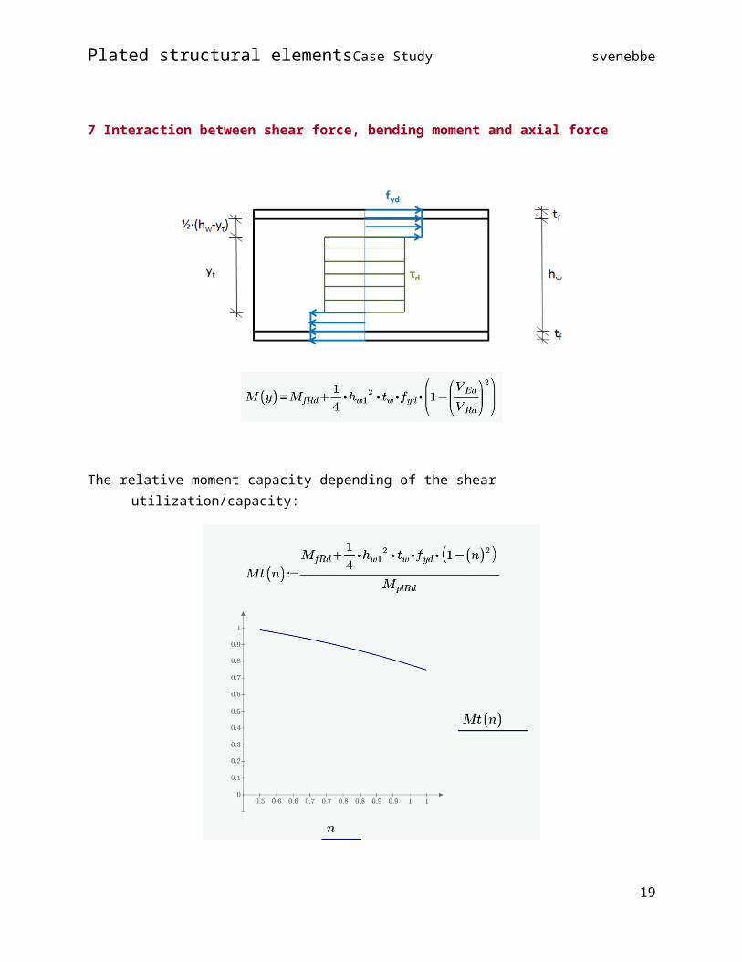
7 Interaction between shear force, bending moment and axial force
The relative moment capacity depending of the shear utilization/capacity:
19

Plated structural elements Case Study svenebbe
According to the Eurocode we have this expression:
If these two expressions for the moment capacity is shown together we have.
20

Plated structural elements Case Study svenebbe
21
Plated structural elements Case Study svenebbe
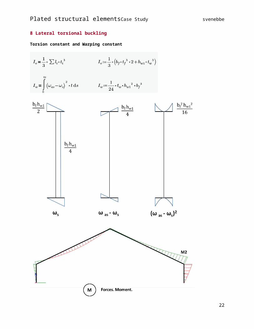
8 Lateral torsional buckling
Torsion constant and Warping constant
22
Plated structural elements Case Study svenebbe
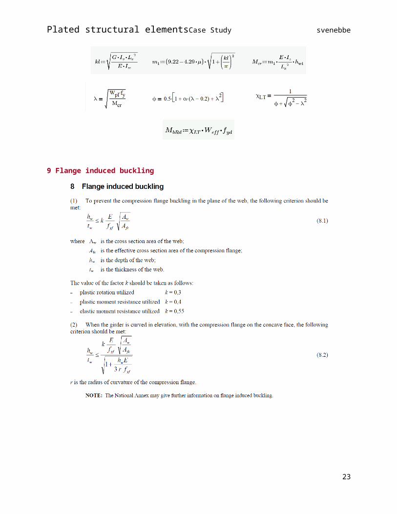
9 Flange induced buckling
23
Plated structural elements Case Study svenebbe
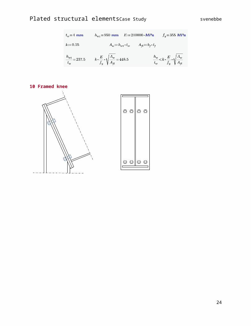
10 Framed knee
11 Critical plate buckling stress for plates with one or two stiffeners in thecompression zone
12 Plastic analysis of beam
13 Support
14 Finite Element Methods of analysis (FEM)
Plate model
24

Plated structural elements Case Study svenebbe
25