staging & air starting march 2012 -...
TRANSCRIPT
HPR Staging & Air Starting By Gary Stroick
Complex Rocket Design Considerations

1. Tripoli Safety Code 2. Technical Considerations 3. Clusters/Air Starts 4. Staging 5. Summary
2 © 2012 Off We Go Rocketry, LLC

3
1. Complex High Power Rocket. A high power rocket that is multi-staged or propelled by a cluster of rocket motors intended for simultaneous ignition at launch or in the air.
2. Stability. A person intending to operate a high power rocket shall determine its stability before flight. This person shall provide documentation of the location of the center of pressure and the center of gravity of the high power rocket to the RSO if the RSO requests same.
3. A person shall not be closer to the launch of a high power rocket than the applicable minimum safe distance set forth in the Safe Distance Table.
© 2012 Off We Go Rocketry, LLC

Motor Selection (Air Start, Cluster or Multi Stage) Propellant Type
▪ Hard Starting Motors (e.g. Greens) – NOT!
▪ AeroTech ▪ Blue Thunder
▪ White Lightning
▪ Cesaroni ▪ Black pellet design permits use of all propellant types
Core Size ▪ Smaller is Better (e.g. usually implies easier starting)
4 © 2012 Off We Go Rocketry, LLC
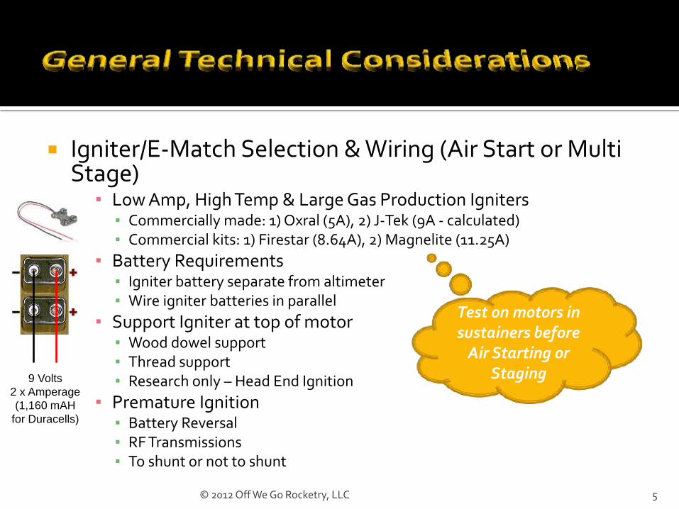
Igniter/E-Match Selection & Wiring (Air Start or Multi Stage)
▪ Low Amp, High Temp & Large Gas Production Igniters ▪ Commercially made: 1) Oxral (5A), 2) J-Tek (9A - calculated) ▪ Commercial kits: 1) Firestar (8.64A), 2) Magnelite (11.25A)
▪ Battery Requirements ▪ Igniter battery separate from altimeter ▪ Wire igniter batteries in parallel
▪ Support Igniter at top of motor ▪ Wood dowel support ▪ Thread support ▪ Research only – Head End Ignition
▪ Premature Ignition ▪ Battery Reversal ▪ RF Transmissions ▪ To shunt or not to shunt
5
Test on motors in sustainers before
Air Starting or Staging
9 Volts
2 x Amperage
(1,160 mAH
for Duracells)
© 2012 Off We Go Rocketry, LLC

Why? Design Considerations Simulation Techniques Altimeter Requirements & Programming Launch Preparation
6 © 2012 Off We Go Rocketry, LLC

Cluster Additional set of challenges at current cert. level
▪ Igniting multiple motors simultaneously
▪ Combining multiple motor types
▪ Centering rings & motor mounts
Air Start All of the above plus
Electronics driven ignitions
Combine motors and delays for adjustable flight profile
7 © 2012 Off We Go Rocketry, LLC

Asymmetrical Thrust One or more motors do not ignite
One or more motors ignite late Resultant Flight Profile
Non-vertical flight
Unstable due to inadequate thrust (wind cocking)
Estimated altitude not reached
Deployment issues ▪ Late (if motor ejection is used)
▪ Zippering
▪ Stripping parachute
8 © 2012 Off We Go Rocketry, LLC

Motor Mounting Alignments
▪ Axially Parallel ▪ Unstable under Asymmetrical
Thrust
▪ Angled through Center of Gravity ▪ Stable under Asymmetrical
Thrust
Motor Retention ▪ Spacing between mounts
Layout Options ▪ Geometries must be
balanced
▪ Heterogeneous mount sizes 9
Inline geometries will always require the largest diameter airframe
© 2012 Off We Go Rocketry, LLC

2) Side by Side – Requires identical motors a) Not an option for Air Starting
3) Alternatives a) Triangle – Also requires identical motors but not an Air Starting option b) Inline – Outside motors must be identical may be used for Air Starting
4) Square – Motors opposite of center must be identical a) Up to two motor types may be used b) Up to one air start is possible
5) Star – Opposite motors must be identical a) Up to three motor types may be used b) Up to two air starts are possible
6) Hexagon – Opposite motors must be identical a) Six motor configuration (There is also a Rectangle Configuration)
i. Up to three motor types may be used ii. Up to two air starts are possible
b) Seven motor configuration i. Up to four motor types may be used ii. Up to three air starts are possible
10 © 2012 Off We Go Rocketry, LLC

Parallel Motor Mounts Add an Inside Tube, name it and mark as motor mount Add other components to the motor mount (engine block, …) If more motor tubes of this type are needed select Cluster
▪ For uniform mounts select the appropriate pattern and follow the Wizard instructions
▪ For non-uniform mounts select “User tube count & radius” option and follow the Wizard instructions
Select a motor mount and add a centering ring ▪ The necessary holes are automatically added ▪ Copy the centering ring and reposition as many times as needed
Canted motor mounts cannot be simulated Copy needed motor files Reduce thrust curve using cosine of motor mount angle
11 © 2012 Off We Go Rocketry, LLC
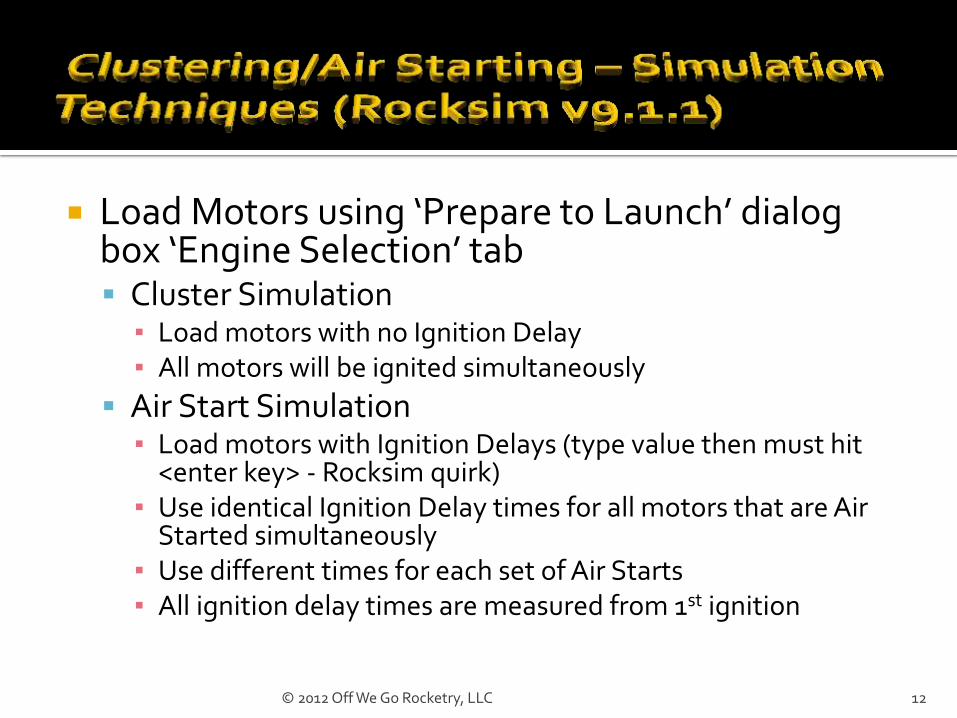
Load Motors using ‘Prepare to Launch’ dialog box ‘Engine Selection’ tab Cluster Simulation
▪ Load motors with no Ignition Delay ▪ All motors will be ignited simultaneously
Air Start Simulation ▪ Load motors with Ignition Delays (type value then must hit
<enter key> - Rocksim quirk) ▪ Use identical Ignition Delay times for all motors that are Air
Started simultaneously ▪ Use different times for each set of Air Starts ▪ All ignition delay times are measured from 1st ignition
12 © 2012 Off We Go Rocketry, LLC

MINIMUM
Timer(s) Pyro channel control based
on: Multiple Timed Delays
Two or more pyro channels
PREFERRED
Accelerometer with timer Pyro channel control based
on: Deceleration Detection
Timed Delay
Recognition of Multiple Deceleration Events
Barometer (for dual deployment of main)
Two or more pyro channels Tilt Detection
13 © 2012 Off We Go Rocketry, LLC
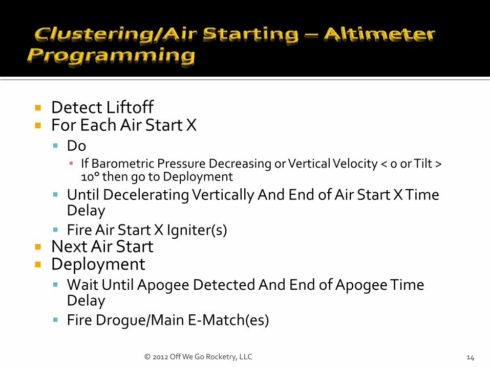
Detect Liftoff For Each Air Start X
Do ▪ If Barometric Pressure Decreasing or Vertical Velocity < 0 or Tilt >
10° then go to Deployment
Until Decelerating Vertically And End of Air Start X Time Delay
Fire Air Start X Igniter(s) Next Air Start Deployment
Wait Until Apogee Detected And End of Apogee Time Delay
Fire Drogue/Main E-Match(es)
14 © 2012 Off We Go Rocketry, LLC

Igniters Always wire in Parallel
Protect wires with Aluminum Tape Consider dipping in pyrogen
Solid Fuel Motors Roughen top grain core Lightly coat top grain core with pyrogen
Motor Mounts Cover empty mounts with Aluminum Tape
15 © 2012 Off We Go Rocketry, LLC

DO’S
Protect igniter wiring Design for motor retention Cant mounts through CG Simulate your flight Learn your altimeter and
programming alternatives Augment igniters and/or
motors Separate batteries for
igniters and altimeters
DON’TS
Use hard starting motors or large core motors
Wire igniters/e-matches in series
Use high ampere igniters
16 © 2012 Off We Go Rocketry, LLC

Why? Design Considerations Simulation Techniques Altimeter Requirements & Programming Launch Preparation
17 © 2012 Off We Go Rocketry, LLC
Additional set of challenges at current cert. level
Multiple flight profiles
Multiple deployments
Combined and individual stability profiles
Combination of multiple motor types
Construction challenges
▪ Sustainer/Booster coupling
▪ Electronics driven ignition
18 © 2012 Off We Go Rocketry, LLC
Failure Modes Stage ignition failure Late stage ignition Coupler malfunction Early, late or no deployment
Resultant Flight Profile Non-vertical flight Estimated altitude not reached Shred Deployment issues
▪ Motor ignition after parachute deployment ▪ Parachute deployment during motor burn ▪ Zippering ▪ Stripping parachute ▪ Negative Altitude Records (i.e., Core Sampling )
19 © 2012 Off We Go Rocketry, LLC

Inline Staging (Single Sustainer) Vertically stacked boosters and sustainer Each booster is discarded after motor burnout
Parallel Staging (Single Sustainer) Similar to Air Starting Boosters are externally attached to the sustainer Each booster separates from the sustainer after its motor
burns out Parasite Staging (Multiple Sustainers)
Similar to Air Starting Sustainers are externally attached to the booster Each sustainer separates after booster burn out
20 © 2012 Off We Go Rocketry, LLC
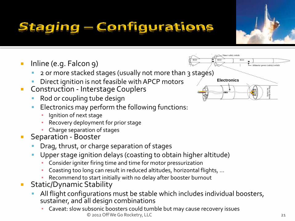
Inline (e.g. Falcon 9) 2 or more stacked stages (usually not more than 3 stages) Direct ignition is not feasible with APCP motors
Construction - Interstage Couplers Rod or coupling tube design Electronics may perform the following functions:
▪ Ignition of next stage ▪ Recovery deployment for prior stage ▪ Charge separation of stages
Separation - Booster Drag, thrust, or charge separation of stages Upper stage ignition delays (coasting to obtain higher altitude)
▪ Consider igniter firing time and time for motor pressurization ▪ Coasting too long can result in reduced altitudes, horizontal flights, … ▪ Recommend to start initially with no delay after booster burnout
Static/Dynamic Stability All flight configurations must be stable which includes individual boosters,
sustainer, and all design combinations ▪ Caveat: slow subsonic boosters could tumble but may cause recovery issues
21
Electronics
© 2012 Off We Go Rocketry, LLC

Parallel (e.g., Delta II) 2 or more external boosters Boosters ignited with sustainer, before, after, or any permutation
Construction - Booster Mounting to Sustainer Aft support options
▪ Guides with a pivot rod and notched guides on booster ▪ Explosive bolts
Fore support options ▪ Slotted booster with guides and pivot rod, sustainer hook ▪ Explosive bolts
Electronics may perform the following functions: ▪ Booster separation and recovery deployment ▪ Sustainer ignition and recovery deployment
Separation - Booster Charge or ejection separation of boosters Separate electronics activation
Static/Dynamic Stability Again sustainer with all booster flight configurations must be stable
Angle pods through CG when possible 22 © 2012 Off We Go Rocketry, LLC

Parasite (e.g., Space Shuttle kind of) 2 or more sustainers Sustainers ignited after booster burn out
Construction – Sustainer mounting to booster Aft support option
▪ Booster has notched supports for sustainer fins
Fore support option ▪ Booster fitting for sustainer launch lug or rail guide
Electronics may perform the following functions: ▪ Sustainer ignition, separation and recovery deployment ▪ Booster recovery deployment
Separation - Sustainer Thrust or charge separation
Static/Dynamic Stability Again booster with all sustainer flight configurations must be stable
23 © 2012 Off We Go Rocketry, LLC

‘Rocket design attributes’ tab Set ‘Number of stages:’ field (default is one)
▪ Use one for Parallel or Parasite designs ▪ Use two or more for Inline designs
‘Rocket design components’ tab Components
▪ Sustainer (Uppermost stage) ▪ Inline
▪ Booster or Booster 1 (1st stage) ▪ Booster 2 (2nd stage) ▪ Design and build each stage
There must be at least one motor mount per stage
▪ Parallel & Parasite ▪ Add one Pod per Booster/Sustainer, name each booster group, leave ejected
during simulations box checked, and set radial position ▪ Select Pod and build Booster/Sustainer with a motor mount
24 © 2012 Off We Go Rocketry, LLC

Load Motors using ‘Prepare to Launch’ dialog box ‘Engine Selection’ tab Inline Simulation
▪ Load motors with appropriate Ignition Delay (coast time) ▪ Booster motors must have a non-zero ejection delay value to stage (Rocksim
quirk) ▪ All motors will be ignited in stage sequence
Parallel Simulation ▪ Load Booster & Sustainer motors with appropriate Ignition Delays ▪ Use identical Ignition Delay times for all motors that are Boosting
simultaneously ▪ Booster separation occurs based on Ejection Delay (must have numeric value) ▪ All ignition delay times are measured from 1st ignition
Parasite Simulation (limited to one sustainer only!) ▪ Load Booster and Sustainer motors with appropriate Ignition Delays ▪ Booster separation occurs based on Ejection Delay (must have numeric value) ▪ All ignition delay times are measured from 1st ignition
25 © 2012 Off We Go Rocketry, LLC

MINIMUM
Timer(s) Pyro channel control based
on: Multiple Timed Delays
Two or more pyro channels
PREFERRED
Accelerometer with timer Pyro channel control based
on: Deceleration Detection
Timed Delay
Recognition of Multiple Deceleration Events
Barometer (for dual deployment of main)
Two or more pyro channels Tilt Detection
26 © 2012 Off We Go Rocketry, LLC
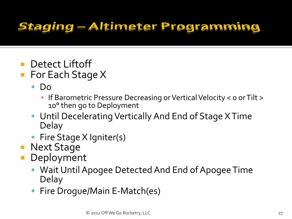
Detect Liftoff For Each Stage X
Do ▪ If Barometric Pressure Decreasing or Vertical Velocity < 0 or Tilt >
10° then go to Deployment
Until Decelerating Vertically And End of Stage X Time Delay
Fire Stage X Igniter(s) Next Stage Deployment
Wait Until Apogee Detected And End of Apogee Time Delay
Fire Drogue/Main E-Match(es)
27 © 2012 Off We Go Rocketry, LLC

Igniters Always wire in Parallel
Consider dipping in pyrogen Solid Fuel Motors
Roughen top grain core
Lightly coat top grain core with pyrogen
28 © 2012 Off We Go Rocketry, LLC

DO’S
Simulate your flight (all configurations)
Learn your altimeter and programming alternatives
Augment igniters and/or motors
Cant mounts through CG (if possible)
Use robust coupling and separation methods
Separate batteries for igniters and altimeters
DON’TS
Use hard starting motors or large core motors in sustainers
Wire igniters/e-matches in series
Use high ampere igniters
29 © 2012 Off We Go Rocketry, LLC

Many aspects of Air Starting and Staging are similar
Altimeter selection & programming
Some design elements
Motor and igniter preparation
Clustering, Air Starting & Staging provide new construction, electronics, and motor challenges at your current certification level
Combine all three for even greater challenges
30 © 2012 Off We Go Rocketry, LLC