stainless steel drain technology - pht group
TRANSCRIPT
www.pht.group
Stainless steel drain technologyProduct Catalog
www.pht.group
Table of Contents
Application overview for drains, channels and floor pans 04
Edge design for slotted-, box channels and floor pans 06
Installation examples for drains 08
Industry drains 10
www.pht.group
LEADING THROUGH INNOVATION
The success of our customers depends on a well-functioning holistic concept in which all individual components work together harmoniously. Whoever produces hygiene-sensitive products bearswith them a certain responsibility. As a successful, producing enterprise you have to keep manyaspects of the requirements and regulations of hygiene and food safety in mind.
We support you in this task and deliver customized hygiene solutions, as well as innovative technology. We develop the perfect fit, specific to your business, complete hygiene-concept andare reliably, along with our expertise, available by your side. In addition to this, after implementingour solution, we continue to be available to you for advice, regular service and for emergencies.
Your PARTNER for HYGIENE and TECHNOLOGY.
www.pht.group
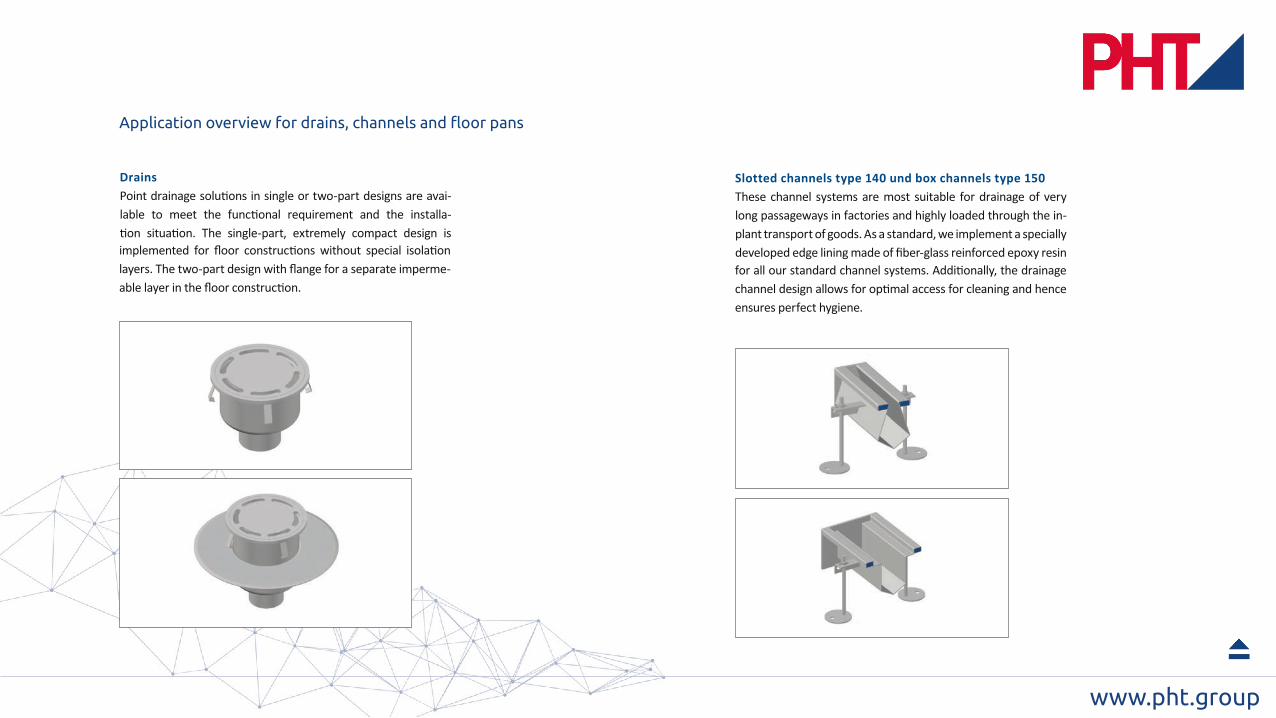
Drains
Application overview for drains, channels and floor pans
www.pht.group
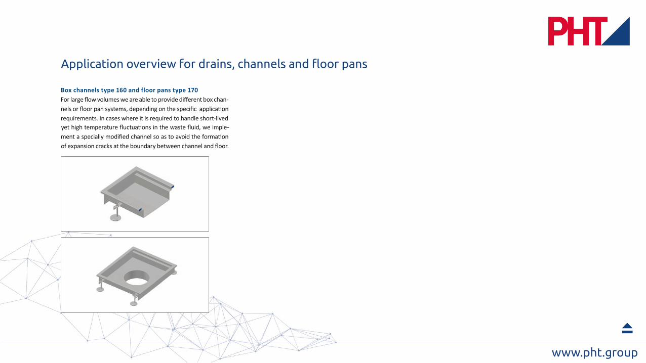
Application overview for drains, channels and floor pans

www.pht.group
40
15
12
RB
12
RB
industrial concrete. The rough surface of this special
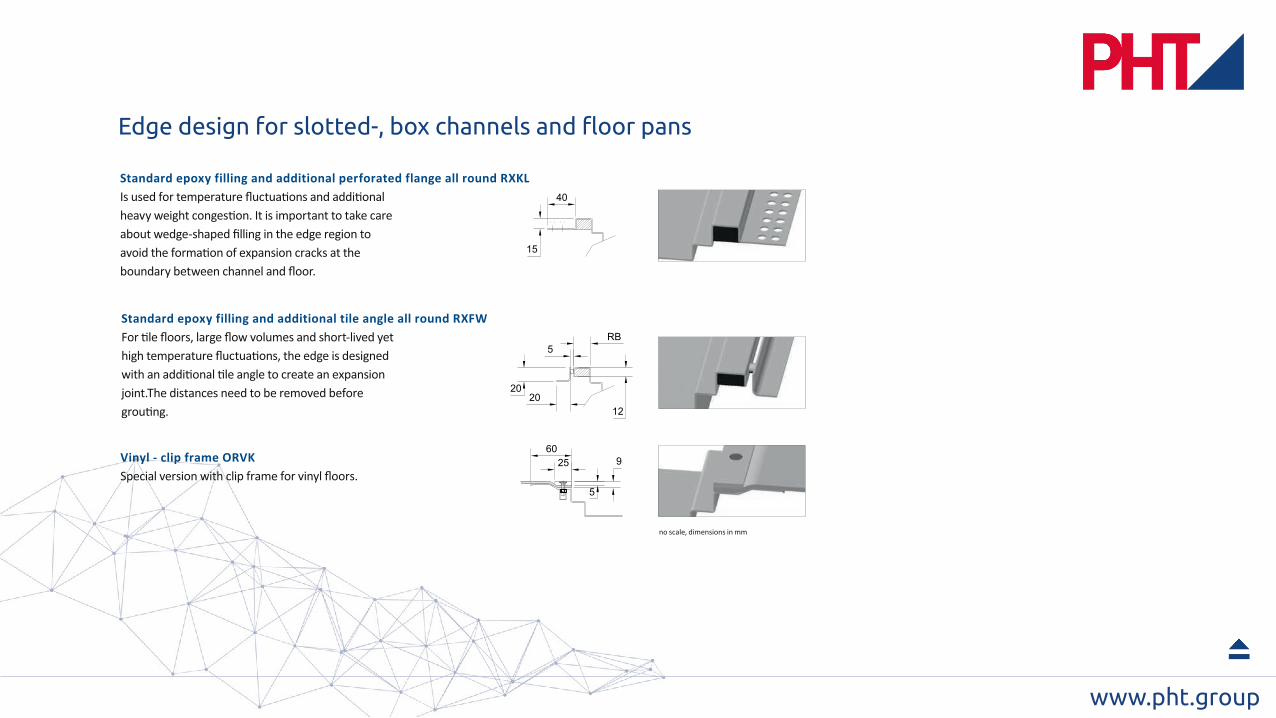
Edge design for slotted-, box channels and floor pans
www.pht.group
40
15
12
RB
2020
5
25 9
5
60
Edge design for slotted-, box channels and floor pans

www.pht.group
Floor coating 1cm
Foundation slab ca. 20cmas required
capillary level
PE - foil
! take care about correct drain pipe level !
Take care about wedge-shaped filling in the edge region
Sealing 1cm
Vapor barrier 0,5cm
Thermal insulation 12cm
Floor coating 1cm
Take care about wedge-shaped filling in the edge region
Pi-plate
Grout topping withgradient 12cm
Sloping screed ca. 20cmas required
Installation examples for drains

www.pht.group
Take care about wedge-shaped filling in the edge region
Floor coating 1cm
Foundation slab ca. 20cmas required
PE - Folie
Blinding layer ca. 5cm
capillary level
PE - foil
Floor coating 1cm
Sealing 1cm
Vapor barrier 0,5cm
Thermal insulation 12cm
Sloping screed ca. 20cmas required
Strip foundation for channel assembling ca. 6cm
Pi-plate
Grout topping withgradient 12cm
Take care about wedge-shaped filling in the edge region
Installation examples for channels
www.pht.group78
140
Ø 110
Ø 210
60
12
5
4
3
Ø 260
1
2345
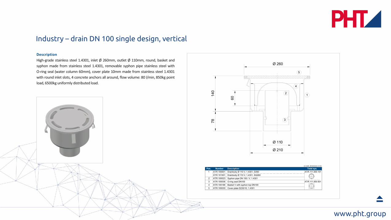
AT.R.100001 Drainbody Ø 110 V, 1.4301, D260 AT.R.111.300.101
Syphon pipe DN 100 / V, 1.4301O-ring seal DN100Basket V with syphon top DN100Cover plate D235/10, 1.4301
AT.R.100023AT.R.100036AT.R.100188AT.R.100030
AT.R.101001 Drainbody Ø 110 V, 1.4301, SQ260
AT.R.111.300.501
Pos. Number Describtion Total sys.no scale, dimensions in mm
Description
Industry – drain DN 100 single design, vertical

www.pht.group
1
2
5
4
3
170 150
Ø 210
Ø11
0
Ø 260
195
1
2
3
4
5
AT.R.100002 Drainbody Ø 110 H, 1.4301, D260 AT.R.112.300.101
Syphon pipe DN 100 / H, 1.4301
O-ring seal DN100Basket H with syphon top DN100
Cover plate D235/10, 1.4301
AT.R.100024
AT.R.100036
AT.R.100228
AT.R.100030
AT.R.101002 Drainbody Ø 110 H, 1.4301, SQ260
AT.R.112.300.501
Pos. Number Describtion Total sys. no scale, dimensions in mm
DescribtionDescription
Industry – drain DN 100 single design, horizontal

www.pht.groupH
A7
81
28
Ø 220
Ø 110
1
2
3
4
6
5
Ø 460
1
2
3
4
5
AT.R.100003 Downbody Ø 110 V, 1.4301,D220,FL AT.R.121.3xx.101
Syphon pipe DN 100 / V, 1.4301
O-ring seal DN100
Basket V with syphon top DN100
Cover plate D235/10, 1.4301
AT.R.100023
AT.R.100036
AT.R.100188
AT.R.100030
AT.R.121.3xx.501
6
Upperbody H250/D260/HA60-220, 1.4301AT.R.100010
Upperbody H350/D260/HA200-320, 1.4301AT.R.100011
121.301.101
60 - 220mm
121.302.101
200 - 320mm
Pos. Number Describtion Total sys.
no scale, dimensions in mm
Total system
adjustment range
AT.R. AT.R.
Description
Industry – drain DN 100 two-part design, horizontal
www.pht.group
195
153
Ø 220
HA
11013
6
6
2
1
3
4
5
Ø 460
12
345
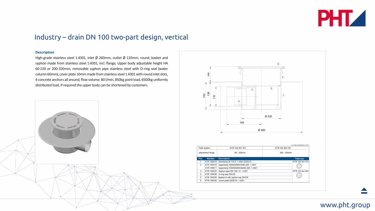
AT.R.100019 Downbody Ø 110 H, 1.4301,D220,FL AT.R.122.3xx.101
Syphon pipe DN 100 / H, 1.4301O-ring seal DN100Basket H with syphon top DN100Cover plate D235/10, 1.4301
AT.R.100024AT.R.100036AT.R.100228AT.R.100030
AT.R.122.3xx.501
6
Upperbody H250/D260/HA60-220, 1.4301AT.R.100010Upperbody H350/D260/HA200-320, 1.4301AT.R.100011
122.301.101
60 - 220mm
122.302.101
200 - 320mm
Pos. Number Describtion Total sys.
no scale, dimensions in mm
Total system
adjustment range
AT.R. AT.R.
Description
Industry – drain DN 100 two-part design, vertical
www.pht.group
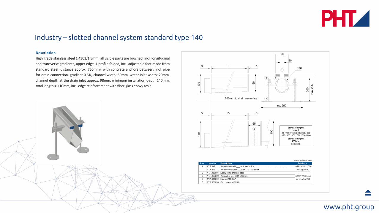
55 L
100
max 2
25
20
60
200
1
3
4
LV
140
5 5
100
60
ca. 250
65
5
2
50 / 100 / 150 / 200 / 250 / 300
350 / 400 / 450 / 500 / 550 / 600
Standard lengthsL (cm)
300 / 600
Standard lengthsLV (cm)
1
2
3
4
AT.R.142 . . . Slotted channel L___cm/h100/20/RX AT.R.142.0xx.020
Adjustable feet St37 L200mm
Hex nut M8 St37
CV connector DN 70
AT.R.103200
AT.R.100072
AT.R.100028
xx = L(cm)/10AT.R.149 . . . Slotted channel LV___cm/h140-100/20/RX
xx = LV(cm)/10
Pos. Number Describtion Total sys.no scale, dimensions in mm
5
Epoxy filling channel edgeAT.R.130005
200mm to drain centerline
020.xx0.941 .R.TA
Description
Industry – slotted channel system standard type 140

www.pht.group
plate made from 12mm stainless steel 1.4301
55 L
100
LV
140
5 5
100
60
65
6
max
225
ca. 300
200
4
1
144104
5
3
2
200mm to drain centerline
50 / 100 / 150 / 200 / 250 / 300350 / 400 / 450 / 500 / 550 / 600
300 / 600
Standard lengthsL (cm)
Standard lengthsLV (cm)
1
234
AT.R.152 . . . Box channel 152 L___cm/h100/12/RX AT.R.152.0xx.112
Adjustable feet St37 L200mmHex nut M8 St37
CV connector DN 70
AT.R.103200AT.R.100072
AT.R.100028
xx = L(cm)/10AT.R.159 . . . Box channel 152 LV___cm/h140-100/12/RX
xx = LV(cm)/105 Cover plate 152 L500/12-1.4301AT.R.191521
Pos. Number Describtion Total sys.no scale, dimensions in mm
6
Epoxy filling channel edgeAT.R.130005AT.R. 159.0xx.112
Description
Industry – box channel system standard type 150

www.pht.group
1 2
5
4
h100
/ h1
40
h100
= 2
25 ..
. h14
0 =
265
78
Ø 210Ø 110
6
3
200
Ø 260
1
2345
AT.R.100006 Drainbody Ø 110 V,D260,100/0/0/0 AT.R.111.3xx.101
Syphon pipe DN 100 / V, 1.4301O-ring seal DN100Basket V with syphon top DN100Cover plate D235/10, 1.4301
AT.R.100023AT.R.100036AT.R.100188AT.R.100030
AT.R.100007 Drainbody Ø 110 V,D260,100/0/100/0
AT.R.111.3xx.501
6 CV connector DN 70AT.R.100028
AT.R.111.341.101
h100 h100h100 h140 h140h140
AT.R.100008AT.R.100009
Drainbody Ø 110 V,D260,140/0/0/0Drainbody Ø 110 V,D260,140/0/140/0
Total system
Positioning
AT.R.111.342.101 AT.R.111.345.101 AT.R.111.346.101
Pos. Number Describtion Total sys.
no scale, dimensions in mm
Description
Industry – drain DN 100 single design, vertical, connection D76 for slotted channels type 140 and box channels type 150
www.pht.group
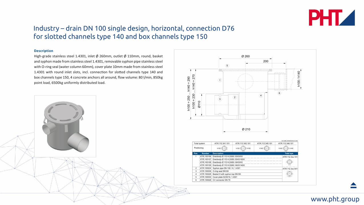
Ø 210
h100
= 2
30 ..
. h14
0 =
270
h100
= 2
50 ..
. h14
0 =
290
Ø11
0
200
1
24
6
3
h100
/ h1
40
Ø 260
5
1
2345
AT.R.100106 Drainbody Ø 110 H,D260,100/0/0/0 AT.R.112.3xx.101
Syphon pipe DN 100 / H, 1.4301O-ring seal DN100Basket H with syphon top DN100Cover plate D235/10, 1.4301
AT.R.100024AT.R.100036AT.R.100228AT.R.100030
AT.R.100107 Drainbody Ø 110 H,D260,100/0/100/0
AT.R.112.3xx.501
6 CV connector DN 70AT.R.100028
AT.R.112.341.101
h100 h100h100 h140 h140h140
AT.R.100108AT.R.100109
Drainbody Ø 110 H,D260,140/0/0/0Drainbody Ø 110 H,D260,140/0/140/0
AT.R.112.342.101 AT.R.112.345.101 AT.R.112.346.101
Pos. Number Describtion Total sys.
no scale, dimensions in mm
Total system
Positioning
Description
Industry – drain DN 100 single design, horizontal, connection D76 for slotted channels type 140 and box channels type 150
www.pht.group
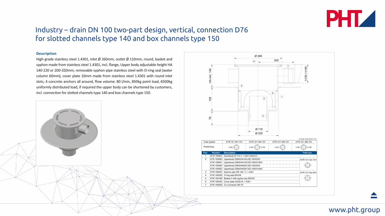
200
128
78
Ø 220
Ø 110
HA
min
. 140
1
2
3
4
5
6
7
Ø 260
h100 / h
140
3
4
5
AT.R.100060 Upperbody D260/HA140-220,100/0/0/0 AT.R.121.3xx.101
Syphon pipe DN 100 / V, 1.4301
O-ring seal DN100
Basket V with syphon top DN100
Cover plate D235/10, 1.4301
AT.R.100023
AT.R.100036
AT.R.100188
AT.R.100030
AT.R.100061 Upperbody D260/HA140-220,100/0/100/0
AT.R.121.3xx.501
6
CV connector DN 70AT.R.100028
AT.R.121.341.101
h100 h100h100 h140 h140h140
AT.R.100062
AT.R.100063
Upperbody D260/HA200-320,140/0/0/0
Upperbody D260/HA200-320,140/0/140/0
Total system
Positioning
AT.R.121.342.101 AT.R.121.345.101 AT.R.121.346.101
1A T.R.100003 Downbody Ø 110 V, 1.4301,D220,FL
2
7
Pos. Number Describtion Total sys.
no scale, dimensions in mm
1A
Description
Industry – drain DN 100 two-part design, vertical, connection D76 for slotted channels type 140 and box channels type 150
www.pht.group
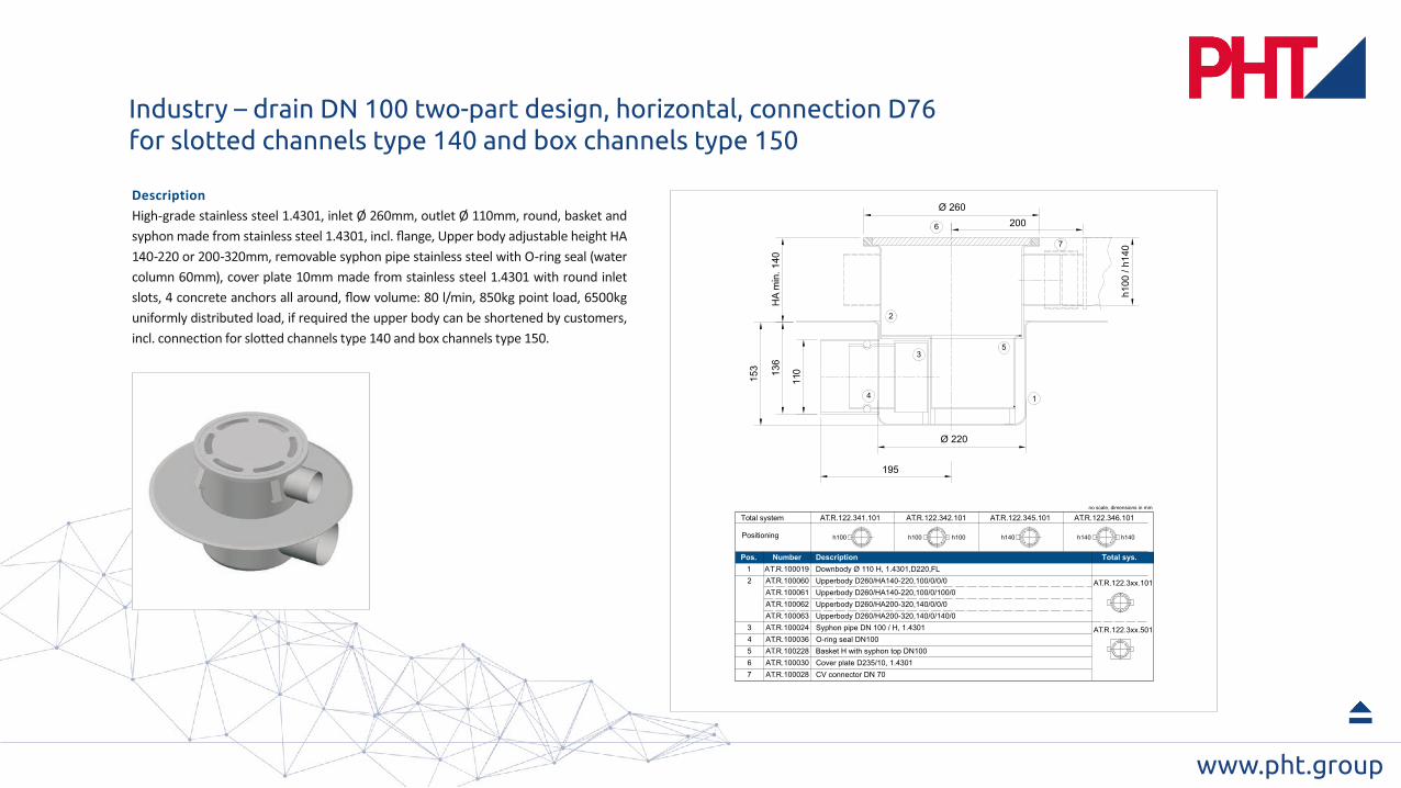
195
153
Ø 220
136
110
4 1
35
200
HA
min
. 140
2
6
7
Ø 260
h100
/ h1
40
345
AT.R.100060 Upperbody D260/HA140-220,100/0/0/0 AT.R.122.3xx.101
Syphon pipe DN 100 / H, 1.4301O-ring seal DN100Basket H with syphon top DN100Cover plate D235/10, 1.4301
AT.R.100024AT.R.100036AT.R.100228AT.R.100030
AT.R.100061 Upperbody D260/HA140-220,100/0/100/0
AT.R.122.3xx.501
6CV connector DN 70AT.R.100028
AT.R.122.341.101
h100 h100h100 h140 h140h140
AT.R.100062AT.R.100063
Upperbody D260/HA200-320,140/0/0/0Upperbody D260/HA200-320,140/0/140/0
Total system
Positioning
AT.R.122.342.101 AT.R.122.345.101 AT.R.122.346.101
1A T.R.100019 Downbody Ø 110 H, 1.4301,D220,FL2
7
Pos. Number Describtion Total sys.
no scale, dimensions in mm
1ADescription
Industry – drain DN 100 two-part design, horizontal, connection D76 for slotted channels type 140 and box channels type 150
www.pht.group
1234
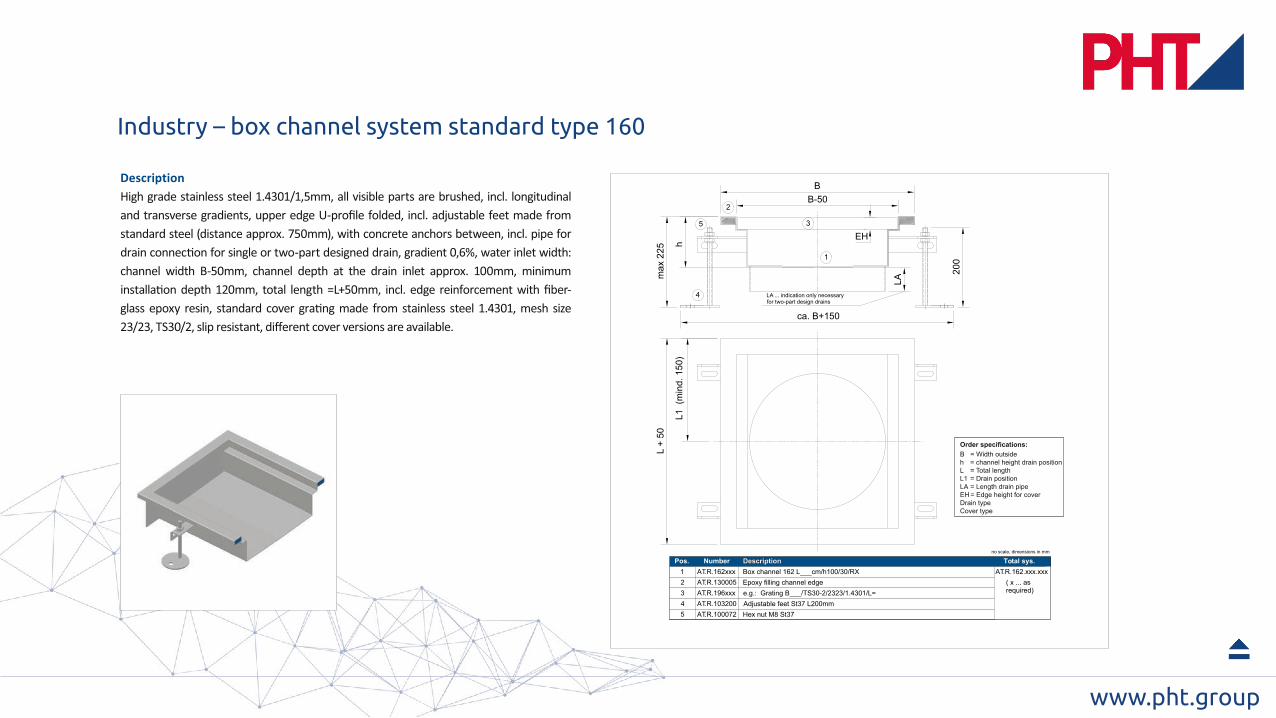
AT.R.162xxx Box channel 162 L___cm/h100/30/RX AT.R.162.xxx.xxx
Adjustable feet St37 L200mmHex nut M8 St37
AT.R.103200AT.R.100072
AT.R.196xxx e.g.: Grating B___/TS30-2/2323/1.4301/L=
Pos. Number Describtion Total sys.no scale, dimensions in mm
( x ... as required)
5
Epoxy filling channel edgeAT.R.130005
max
225
5
4
BB-50
ca. B+150
200
L +
50
L1 (
min
d. 1
50)
h
LA
1
3
2
EH
LA ... indication only necessaryfor two-part design drains
Description
B = Width outsideh = channel height drain positionL = Total lengthL1 = Drain positionLA = Length drain pipeEH = Edge height for coverDrain typeCover type
Industry – box channel system standard type 160

www.pht.group
max
225
5
4
WB
200
WL
L1W
T
LA
1
3
B1EB x EL
grating width RB = WB - 50
grat
ing
leng
th R
L =
WL
- 50
EH
LA ... indication only necessaryfor two-part design drains
2
Pos. Number Describtion Total sys.1234
AT.R.172xxx Floor pan 172 WLxWB/WT/30/RX AT.R.172.xxx.xxx
Adjustable feet St37 L200mmHex nut M8 St37
no scale, dimensions in mm
AT.R.103200AT.R.100072
( x ... as required)AT.R.197xxx e.g.: Grating LxBcm/TS30-2/23x23-1.4301
5
Epoxy filling channel edgeAT.R.130005
Description
WL = Length outsideWB = Width outsideWT = DepthL1/B1 = Drain positionLA = Length drain pipeEH = Edge height for coverDrain typeGrating type
Industry – floor pan system standard type 170
www.pht.group
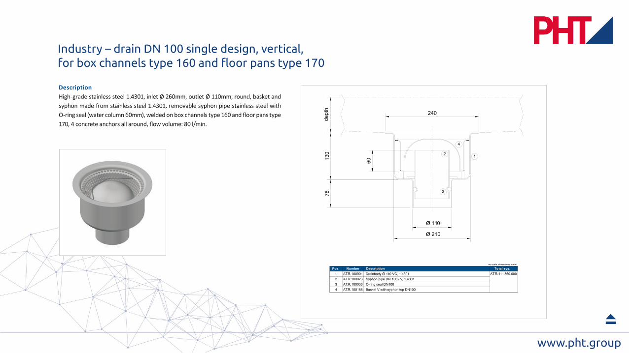
7813
0
Ø 110
Ø 210
60
12
4
3
240
dept
h
1234
AT.R.100901 Drainbody Ø 110 VC, 1.4301 AT.R.111.360.000Syphon pipe DN 100 / V, 1.4301O-ring seal DN100Basket V with syphon top DN100
AT.R.100023AT.R.100036AT.R.100188
Pos. Number Describtion Total sys.no scale, dimensions in mm
Description
Industry – drain DN 100 single design, vertical, for box channels type 160 and floor pans type 170

www.pht.group
ca. 240
1
24
3
170 15
0
Ø 210
Ø11
0
195dept
h
1234
AT.R.100902 Drainbody Ø 110 HC, 1.4301 AT.R.112.360.000Syphon pipe DN 100 / H, 1.4301O-ring seal DN100Basket H with syphon top DN100
AT.R.100024AT.R.100036AT.R.100228
Pos. Number Describtion Total sys.no scale, dimensions in mm
Description
Industry – drain DN 100 single design, horizontal, for box channels type 160 and floor pans type 170
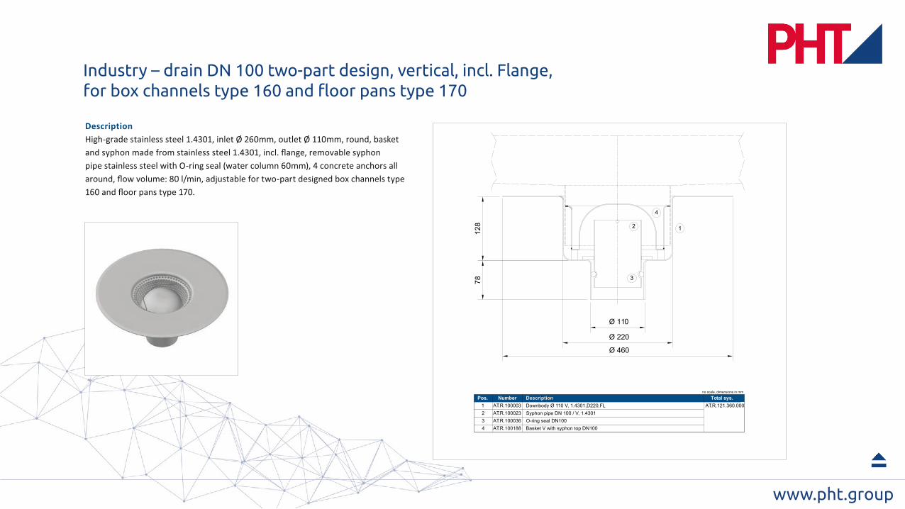
www.pht.group12
878
Ø 220
Ø 110
Ø 460
3
12
4
1234
AT.R.100003 Downbody Ø 110 V, 1.4301,D220,FL AT.R.121.360.000Syphon pipe DN 100 / V, 1.4301O-ring seal DN100Basket V with syphon top DN100
AT.R.100023AT.R.100036AT.R.100188
Pos. Number Describtion Total sys.no scale, dimensions in mm
Description
Industry – drain DN 100 two-part design, vertical, incl. Flange,for box channels type 160 and floor pans type 170
www.pht.group
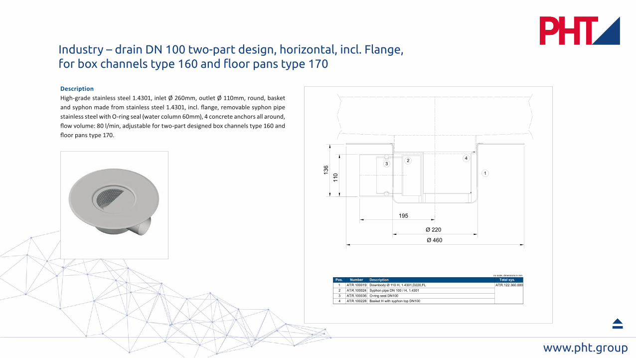
Ø 460
195
Ø 220
11013
6
1
23
4
1234
AT.R.100019 Downbody Ø 110 H, 1.4301,D220,FL AT.R.122.360.000Syphon pipe DN 100 / H, 1.4301O-ring seal DN100Basket H with syphon top DN100
AT.R.100024AT.R.100036AT.R.100228
Pos. Number Describtion Total sys.no scale, dimensions in mm
Description
Industry – drain DN 100 two-part design, horizontal, incl. Flange,for box channels type 160 and floor pans type 170
www.pht.group
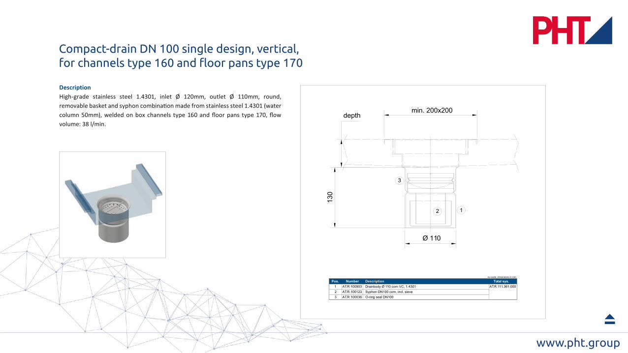
12
3
min. 200x200
Ø 110
130
depth
1
2
3
AT.R.100903 Drainbody Ø 110 com VC, 1.4301 AT.R.111.361.000
Syphon DN100 com, incl. sieve
O-ring seal DN100
AT.R.100123
AT.R.100036
Pos. Number Describtion Total sys.no scale, dimensions in mm
Description
Compact-drain DN 100 single design, vertical, for channels type 160 and floor pans type 170
www.pht.group
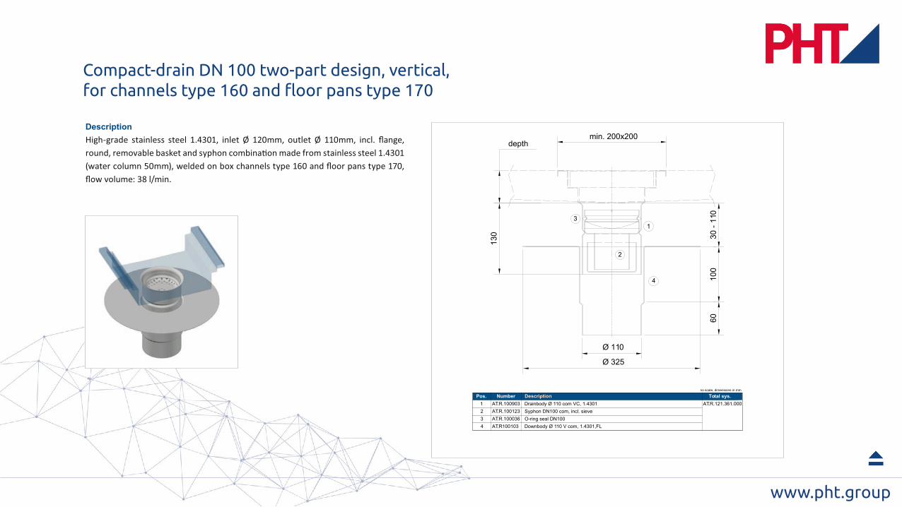
Description
1
2
3
min. 200x200
130
Ø 110
6010
0
4
30 -
110
Ø 325
depth
123
AT.R.100903 Drainbody Ø 110 com VC, 1.4301 AT.R.121.361.000Syphon DN100 com, incl. sieveO-ring seal DN100
AT.R.100123AT.R.100036
4 Downbody Ø 110 V com, 1.4301,FLAT.R100103
Pos. Number Describtion Total sys.no scale, dimensions in mm
Description
Compact-drain DN 100 two-part design, vertical, for channels type 160 and floor pans type 170
www.pht.group
PHT Germany – NorthAuf dem Tigge 33D-59269 BeckumTel. +49 (0) 25 21-82 39 [email protected]
PHT Germany – SouthFörchenholzstraße 19D-83646 Bad TölzTel. +49 (0) 80 41-799 [email protected]
PHT AustriaHeinrich Schneidmadl-Str. 15A-3100 St. PöltenTel. +43 (0) 27 42-90 01 31 [email protected]
PHT BeneluxDen Uitvanck 20NL-5688 XG OirschotTel. +31 (0) [email protected]
PHT South Africa137 Edison CrescentCenturion 0157Tel. +27 (0) 861 [email protected]