stainless steels in nuclear industry usage and special considerations issda nov 2014.pdf ·...
TRANSCRIPT

Stainless Steels in Nuclear Industry
– Usage and Special Considerations VIVEKANAND KAIN
BHABHA ATOMIC RESEARCH CENTRE, MUMBAI [email protected]
25 Years of Indian Stainless Steel Development Association
New Delhi, November 7, 2014
OUTLINE
NUCLEAR INDUSTRY: Constituents
INDIAN NUCLEAR POWER PROGRAM – STATUS
MAIN DEGRADATION MODES IN SERVICE
STAINLESS STEELS IN NUCLEAR INDUSTRY
“L” AND “LN” VARITIES: MAIN REQUIREMENTS
“NAG” STAINLESS STEELS FOR RECYCLE PLANTS

Nuclear Industry
Nuclear Reactors
Nuclear Spent
Fuel Reprocessing
& Waste Management
Plants
Heavy Water
Plants ITER
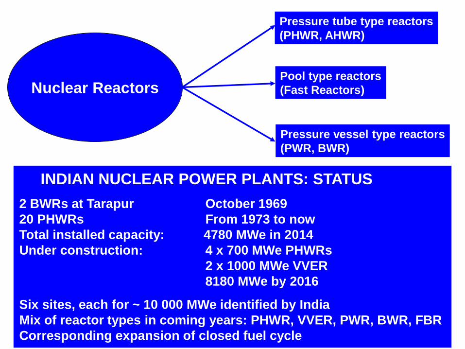
Nuclear Reactors
Pressure tube type reactors
(PHWR, AHWR)
Pool type reactors
(Fast Reactors)
Pressure vessel type reactors
(PWR, BWR)
INDIAN NUCLEAR POWER PLANTS: STATUS
2 BWRs at Tarapur October 1969
20 PHWRs From 1973 to now
Total installed capacity: 4780 MWe in 2014
Under construction: 4 x 700 MWe PHWRs
2 x 1000 MWe VVER
8180 MWe by 2016
Six sites, each for ~ 10 000 MWe identified by India
Mix of reactor types in coming years: PHWR, VVER, PWR, BWR, FBR
Corresponding expansion of closed fuel cycle

Dominant degradation mechanisms in
carbon steel/stainless steel
in Swedish nuclear power plants (2002)
Cause of IGSCC in reactors
Cracking data base as a basis for risk
informed inspection by Karen Gott, 10th International
conference on environmental degradation of materials in
nuclear power systems – Water reactors
Worldwide Corrosion Events in LWR
(1995 – 2004) R. Kilian, Areva, 2008
Stress corrosion cracking: 39%
Flow accelerated corrosion: 33.6%
Corrosion: 18.7%
Pitting: 1.4%
Under deposit corrosion/MIC: 5.3%
Galvanic corrosion: 1.1%
H induced cracking: 1.1% Core shroud SCC: non sensitized SS
Fukushima Core Shroud,
Shoji et al

STAINLESS STEELS IN NUCLEAR INDUSTRY
Nuclear Power Plants:
SS 316NG (Nuclear Grade)
SS 304L
SS 304LN
SS 403M
17 – 4 PH / 13 – 8 Mo
SS 440C
SS 420 mod
SS 410
SS 321
Nuclear Fuel Reprocessing & Waste management Plants:
SS 304L
SS 304L (Nitric Acid Grade - NAG)
SS 310L (NAG)
SFSP: SS304L/316L
Weld consumables
220 MWe PHWR:
~ 1000 T SS
15,000 m weld length

Surface area exposed to process fluid in a 540 MWe nuclear recator:
Liqid Zone Control system: SS 304L 140 m2
Liquid Poison Injection System SS 304L 35 m2
End Shield Cooling System SS 304L 1000 m2
Calandria Vault Cooling System SS 304L 2000 m2
SFSB Cooling System SS 304L 3000 m2
Moderator System SS 304L 3500 m2
Active Process Water System SS 304L 3500 m2
Service Water System SS 304L 2500 m2
Condensate System SS 304L 6250 m2
Feed Water System SS 304L 1400 m2
Make up Water System SS 304L 20 m2
Auxiliary Cooling Water System SSs 2000 m2
Non active Process water System SS 304L 1000 m2
Condenser Circulating Water System SSs 100 m2
Auxiliary Service Water System SSs 50 m2
Reactivity Control Mechanism: Various SSs
Total SS surface area: 20,000 m2

Long term service in nuclear reactors: austenitic SS in AHWR
• SS 316NG: Resists sensitization, LTS and sensitization induced IGSCC
• However, more prone to embrittlement of the weldment (ferrite phase)
due to aging at operating temperature for long term
• SS 304LN: Assessment of LTS, IGSCC and LTE being established
• Requires higher N levels for resistance against LTS and IGSCC
LOW TEMPERATURE SENITIZATION (LTS)
FOR SS 304L/LN STAINLESS STEELS
Creff(N) = % Cr – 0.2 (%Ni)
– 100 (%C) + 9.2N
Creff(N) > 16 would ensure that
LTS in the weld HAZ would not develop
to a level that makes it prone to SCC,
due to sensitization, in 100 years of
design life
Creff(N) < ?? NEED LARGER DATABASE
Creff(N) 11.38 14.53 15.34 16.46
Kain et al

APPROACHES:
1. Addition of oversized solute alloying
elements like Ce, Hf, Zr, Gd, and Pt
2. Grain Boundary Engineering:
• Twin/special grain boundaries
• Random grain boundaries
3. Heat Treatment to create initial segregation of Cr
– This would retard the onset of RIS
Making SS Resistant to RIS (Resistant against Irradiation assisted SCC in reactors)
Carbides after 6500C, 100h
SS 316 (0.06% C): Beneficial effect of Ce on thermal sensitization
Attacked Cr depletion after 6500C, 100h
No Ce 0.01wt% Ce 0.01wt% Ce No Ce
Bruemmer et al, JNM 1999
Kain et al, BARC

Controlling grain boundary nature to control
sensitization, IGC and IGSCC
1. Increase the fraction of special (S = 3 - 29) grain boundaries
( ~ 5% cold working + controlled solution annealing increases
the fraction of twin boundaries)
Makes precipitation of carbides difficult and improves resistance
to sensitization.
2. Increase fraction of random (S > 29) grain boundaries
( ~ 80% cold working + controlled solution annealing increases
the fraction of random boundaries)
Improves resistance to sensitization, IGC and IGSCC
1. Low carbon (<0.03%) grades
2. Stabilized (with Ti, Nb) grades
3. Use Solution annealed components
Methods to control sensitization & Inter Granular Corrosion

TWIN ENGINEERED STAIBNLESS STEELS Kokawa et at 2002
5% CW +
927°C, 72 h
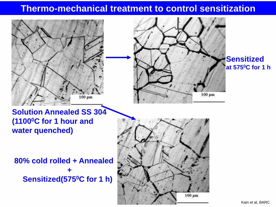
Solution Annealed SS 304
(11000C for 1 hour and
water quenched)
Sensitized at 5750C for 1 h
80% cold rolled + Annealed
+
Sensitized(5750C for 1 h)
Thermo-mechanical treatment to control sensitization
Kain et al, BARC
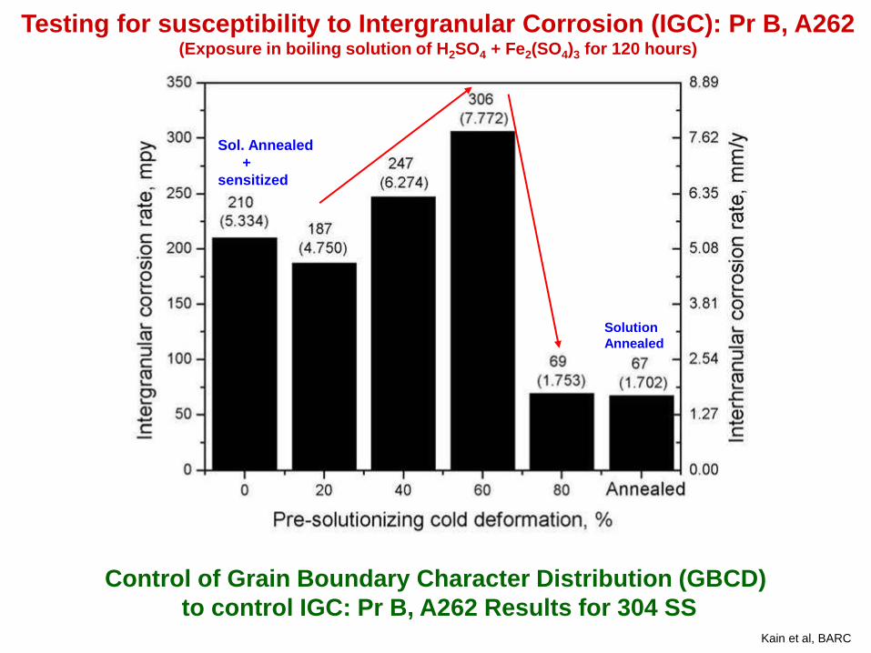
Control of Grain Boundary Character Distribution (GBCD)
to control IGC: Pr B, A262 Results for 304 SS
Sol. Annealed
+
sensitized
Solution
Annealed
Testing for susceptibility to Intergranular Corrosion (IGC): Pr B, A262 (Exposure in boiling solution of H2SO4 + Fe2(SO4)3 for 120 hours)
Kain et al, BARC

After DL-EPR test
After IGC
Test - Practice B
ASTM test
Severe IGC attack
No IGC attack
No attack
Deep attack
at grain
boundaries
Kain et al, BARC

Intergranular cracking Mixed mode of cracking
No cracks at high
percentage of reduction
After 200 hours testing in boiling 25% NaCl solution (pH=1.5):G 123, ASTM
80% CW + Sol. Annealed + Sensitized
Testing for susceptibility to IGSCC: U bent (strained) samples of cold
rolled, annealed and sensitized SS 304
40% CW+
Sol. Annealed
+ Sensitized
20% CW
+ Sol. Annealed
+ Sensitized
Kain et al, BARC

Main results of the
Orientation Imaging
Microscopy analysis
Tota
l (
S 3
– S
29)
Fracti
on
S
3 B
ou
nd
ary
Fract
ion
Fraction of random
boundaries increased
from 32% in as received
material to 77% in the
sample with 80% CW +
Annealing.
Connectivity of
random – random
boundary is required.
This required >75%
random boundaries.
U – Unidirectional Rolling
CR – Cross Rolling Kain et al, BARC

-250 -200 -150 -100 -50 0 50 100 150 200 250 300
0
50
100
150
200
-250 -200 -150 -100 -50 0 50 100 150 200 250 300
0
50
100
150
200
750C
41J
Absorbed energy v/s test temperature for AISI 403 SS
Before irradiation
After irradiation
Ab
so
rbed
En
erg
y, J
Test Temperature,0 C
SS 403 Modified: End Fitting Elements SS 403 Modified
SS 403
(Indian)
Carbon 0.15 0.06-0.15
Manganese 1.0 0.25-0.80
Phosphorus 0.04 0.03 max
Sulphur 0.03 0.03 max
Chromium 11.5-13.0 11.5-13.0
Nickel - 0.5 max
Silicon 0.5 0.5 max
Cobalt - 0.025 max
Boron - -
Copper - 600 ppm
max
Oxygen - 100 ppm
max
Nitrogen - 250 ppm
max
Hydrogen - 2 ppm max
Impurities
Cu+V+Sb+Al
+As
- 1500 ppm
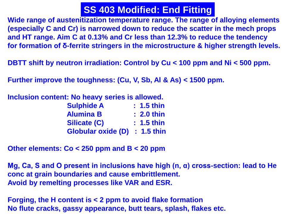
Wide range of austenitization temperature range. The range of alloying elements
(especially C and Cr) is narrowed down to reduce the scatter in the mech props
and HT range. Aim C at 0.13% and Cr less than 12.3% to reduce the tendency
for formation of δ-ferrite stringers in the microstructure & higher strength levels.
DBTT shift by neutron irradiation: Control by Cu < 100 ppm and Ni < 500 ppm.
Further improve the toughness: (Cu, V, Sb, Al & As) < 1500 ppm.
Inclusion content: No heavy series is allowed.
Sulphide A : 1.5 thin
Alumina B : 2.0 thin
Silicate (C) : 1.5 thin
Globular oxide (D) : 1.5 thin
Other elements: Co < 250 ppm and B < 20 ppm
Mg, Ca, S and O present in inclusions have high (n, α) cross-section: lead to He
conc at grain boundaries and cause embrittlement.
Avoid by remelting processes like VAR and ESR.
Forging, the H content is < 2 ppm to avoid flake formation
No flute cracks, gassy appearance, butt tears, splash, flakes etc.
SS 403 Modified: End Fitting
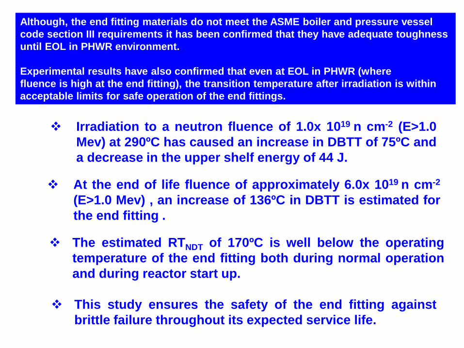
Irradiation to a neutron fluence of 1.0x 10¹⁹ n cm-2 (E>1.0
Mev) at 290ºC has caused an increase in DBTT of 75ºC and
a decrease in the upper shelf energy of 44 J.
At the end of life fluence of approximately 6.0x 10¹⁹ n cm-2
(E>1.0 Mev) , an increase of 136ºC in DBTT is estimated for
the end fitting .
This study ensures the safety of the end fitting against
brittle failure throughout its expected service life.
The estimated RTNDT of 170ºC is well below the operating
temperature of the end fitting both during normal operation
and during reactor start up.
Although, the end fitting materials do not meet the ASME boiler and pressure vessel
code section III requirements it has been confirmed that they have adequate toughness
until EOL in PHWR environment.
Experimental results have also confirmed that even at EOL in PHWR (where
fluence is high at the end fitting), the transition temperature after irradiation is within
acceptable limits for safe operation of the end fittings.

Presence of Sigma Phase in 17-4 PH Bobbin Shaft: DELETERIOUS s PHASE
s
Retained austenite
168 – 200 HV
Martensite
320 – 335 HV
Martensite
350 – 380 HV
Retained Austenite in SS 403 of End-Fitting Ferrite in Martensitic Stainless Steel SS 410
Loss of impact toughness
a
Kain et al, BARC

17 – 4 PH STAINLESS STEEL FOR FUELLING MACHINE
Shielding plug, Sealing plug
Cr: 15.5 – 17
Ni: 3 – 5
Cu: 3 – 5
Si: 1 max
Mn: 1 max
Nb: 0.15 – 0.45
C: 0.07 max
S: 0.03 max
P: 0.04 max
H 1100 condition: Sol Ann at 1035°C, 30 min + 580°C, 4 h, AC
During melting, aim to keep:
Cr < 16.5% to keep d- ferrite under control
C < 0.04 %to keep Mf ~ 30°C
Nb/C < 6 to keep impact toughness
High resistance to sliding wear, good toughness, shock resistance

Contamination during fabrication
Embedded iron in stainless steels Iron corrodes in moist atmospheres in coastal areas during
storage
Concentration of chlorides
Iron oxides are voluminous, causing high stresses
TGSCC of even annealed stainless steels during storage
· Organic contamination Grease, Oil, Crayon markings, Paint, Adhesive tape, Sediments,
Other sticky deposits
In aggressive environments it induces crevice corrosion
Removal essential in order to remove iron contamination
· Welding related contaminants Slag from coated electrodes
Heat tint
Arc strikes
Welding stop points
Weld spatter
Cold work/heavy machining leading to surface cold work/strain
Chloride build up during long term storage

16h exposure to Boiling Magnesium Chloride
Cracking throughout width along longitudinal direction
Circumferential cracking
10h exposure to Boiling MgCl2
Condenser tubes of SS 304: High residual stress
Stretch straightening – Longitudinal stresses ~ 2 Kg/mm2
Roller straightening:
Circumferential stresses
~ 20 Kg/mm2
Kain et al, BARC
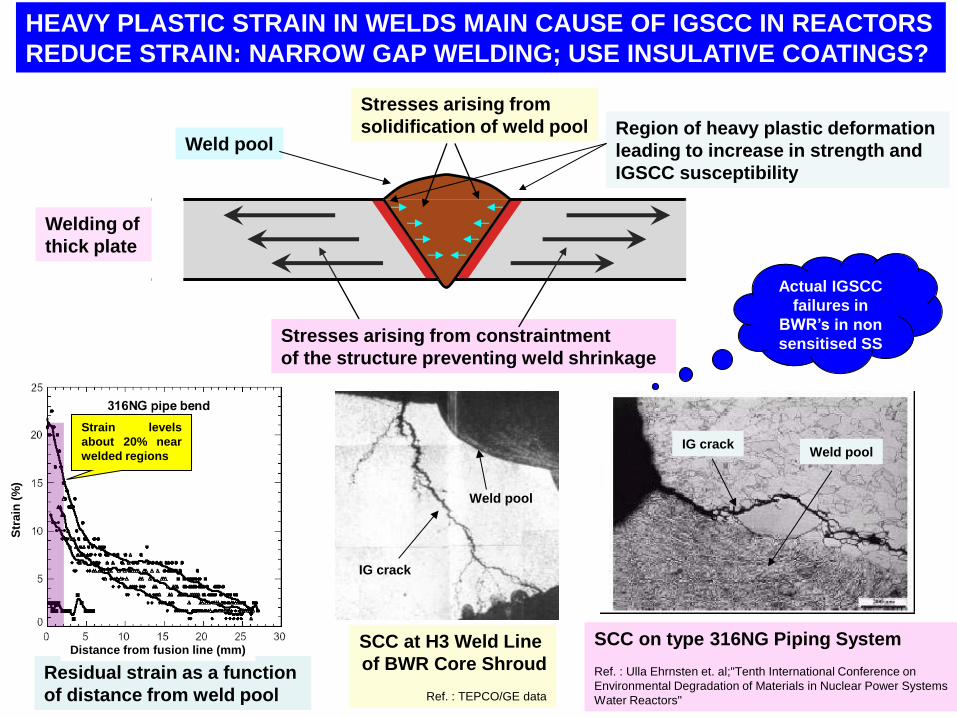
Stresses arising from
solidification of weld pool
Stresses arising from constraintment
of the structure preventing weld shrinkage
Region of heavy plastic deformation
leading to increase in strength and
IGSCC susceptibility
Weld pool
Welding of
thick plate
SCC at H3 Weld Line
of BWR Core Shroud
Ref. : TEPCO/GE data
IG crack
Weld pool
Actual IGSCC
failures in
BWR’s in non
sensitised SS
SCC on type 316NG Piping System
Ref. : Ulla Ehrnsten et. al;"Tenth International Conference on
Environmental Degradation of Materials in Nuclear Power Systems
Water Reactors"
IG crack Weld pool
Residual strain as a function
of distance from weld pool
Str
ain
(%
)
Distance from fusion line (mm)
Strain levels
about 20% near
welded regions
HEAVY PLASTIC STRAIN IN WELDS MAIN CAUSE OF IGSCC IN REACTORS
REDUCE STRAIN: NARROW GAP WELDING; USE INSULATIVE COATINGS?

The Tube side of weldment: Transformation of delta ferrite to sigma phase
and cracking during welding
5 – 6 % delta ferrite stringers in the tubes
KEEP DELTA FERRITE IN BASE METAL << 0.2%
After welding: HAZ
After welding: away from HAZ
Sigma
phase
Same morphology of the cracks and
sigma phase
Kain et al, BARC
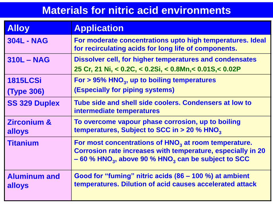
Alloy Application
304L - NAG For moderate concentrations upto high temperatures. Ideal
for recirculating acids for long life of components.
310L – NAG Dissolver cell, for higher temperatures and condensates
25 Cr, 21 Ni, < 0.2C, < 0.2Si, < 0.8Mn,< 0.01S,< 0.02P
1815LCSi
(Type 306)
For > 95% HNO3, up to boiling temperatures
(Especially for piping systems)
SS 329 Duplex Tube side and shell side coolers. Condensers at low to
intermediate temperatures
Zirconium &
alloys
To overcome vapour phase corrosion, up to boiling
temperatures, Subject to SCC in > 20 % HNO3
Titanium For most concentrations of HNO3 at room temperature.
Corrosion rate increases with temperature, especially in 20
– 60 % HNO3, above 90 % HNO3 can be subject to SCC
Aluminum and
alloys
Good for “fuming” nitric acids (86 – 100 %) at ambient
temperatures. Dilution of acid causes accelerated attack
Materials for nitric acid environments
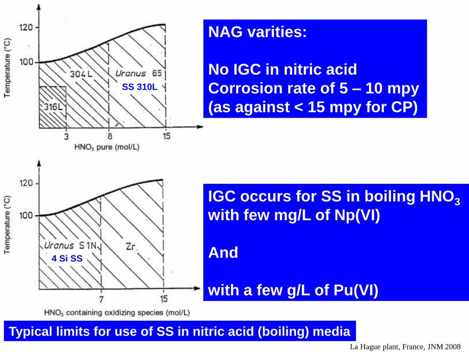
Typical limits for use of SS in nitric acid (boiling) media La Hague plant, France, JNM 2008
IGC occurs for SS in boiling HNO3
with few mg/L of Np(VI)
And
with a few g/L of Pu(VI)
SS 310L
4 Si SS
NAG varities:
No IGC in nitric acid
Corrosion rate of 5 – 10 mpy
(as against < 15 mpy for CP)

IGC testing in HNO3 environments: Sensitization induced
Chemical composition based parameter
Creffective = % Cr – 0.18 (%Ni) – 100 (%C)
Microstructure
Sensitize at 6770 C for 20 minutes: Coverage < 50 %
Sensitize at 6770 C for 1 hour: Coverage < 100 %
And Creffective > 14.0
SS 304 L would be resistant to
IGC in practice C, A262, ASTM
Vivekanand Kain, MSD, BARC, Mumbai Kain et al, BARC

Surfaces
exposed
to
oxidizing
acid
Dissolution of inclusions
Mechanism of
End Grain
Corrosion
Resultant IGC
Kain et al, BARC

End Grain Corrosion Test
• Exposure to boiling solutions
of 9N HNO3 + 1 g Cr+6/liter
• 4 periods of 24h each
304L NAG
304L Susceptibility to
End Grain Corrosion
• “Active” inclusions
• Flow lines and segregation
of Cr, Si and P along it
Material Corr. Rate Depth of
(mpy) Attack
304L (CP) 1020 500 mm
304L (NAG) 770 250 mm
Ti-5Ta-1.8Nb 0.17 Not visible
Welded
Ti-5Ta-1.8Nb 0.28 Not visible Kain et al, BARC

Corrosion in Magnox fuel dissolver:
Vapour phase
Local metal loss 2 - 5 mm deeper
than in base metal
Corrosion of seam welds
(End Grain Corrosion)
Forgings
(End Grain Corrosion)
Set in branches R D Shaw, Br Corr J, 1990

Improved Corrosion Resistance of Type 304 L Stainless Steel
– Nitric Acid Grade (NAG)
Element Composition, Wt.%
304L CP 304L NAG
C < 0.03 < 0.025
Si < 1.0 < 0.25
Mn < 2.0 < 2.0
P < 0.045 < 0.018
S < 0.03 < 0.015
Cr 18 – 20 18 – 20
Ni 8 – 12 9 - 11
O ~100 ppm < 50 ppm
N < 500 ppm < 200 ppm
Control of:
Sensitization: levels of C, Ni and Cr and Si & P
End Grain Corrosion: sulfide inclusions and segregation of Cr, Si and P
Uniform Corrosion: controlled cold work, nature of grain boundaries
Inclusions: Total (A +B + C + D) < 4.0 [C,D thin < 1.5, D thick < 1, others < 0.5]

304L CP G = 4.0 304L NAG G = 6.5
After resolution annealing (11000C, 30 min, WQ) and 6770C, 1h sensitization.
Average Corrosion Rate in five periods of practice C, A262
Heat Treatment Corrosion Rate (mpy)
CP NAG
As Received 12.0 4.0
AR + Sensitized 36.0 6.5
AR + Resolutionized +
Sensitized
44.0 7.0 Kain et al, BARC
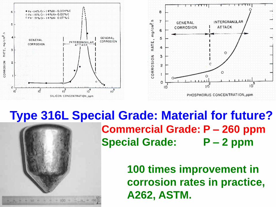
Type 316L Special Grade: Material for future? Commercial Grade: P – 260 ppm
Special Grade: P – 2 ppm
100 times improvement in
corrosion rates in practice,
A262, ASTM.

Liquid phase
Condensate
phase
Condensate phase corrosion in nitric acid:
IGA of annealed SS
Cr content vs. corrosion rate in boiling nitric acid
IGC OF NON-SENSITIZED STAINLESS STEELS IN
BOILING NITRIC ACID CONTAINING OXIDIZING IONS
Performance vs. Making, Shaping and Treating
of Stainless Steels – A few examples
Common melting techniques:
Arc/air induction melting followed by refining using
Argon Oxygen Decarburization (AOD)/Vacuum Oxygen
Decarburization (VOD) techniques
Special melting techniques:
Arc/air induction melting followed by refining using
Electro Slag Refining (ESR)
Arc/air induction melting followed by refining using
Creusot-Loire-Uddeholm (CLU) or Laddle Injection Control (LIC)
techniques

Cleanliness of alloy from different melting techniques
ESR produces clean stainless steels
1 2 3 4 5 6
Sulfide stringers Alumina
Oxides
Alumina

THANK YOU
INDIAN SS INDUSTRY HAS
THE CAPABILITY TO MEET
ALL THE REQUIREMENTS OF SS
NEEDS TO WORK CLOSELY WITH
NUCLEAR INDUSTRY
AND ESTABLISH THE BEHAVIOUR
OF SS IN GIVEN APPLICATION