stand 11.10.04 building instructions for the roke as w 19instructions... · • please do not...
TRANSCRIPT

Bauanleitung zu ROKE AS W 19 Seite
ROKE - Modelle, Roland Kern, Rosenstrasse 2, D - 72827 Wannweil, Telefon 0049 7121 - 57 336
1
Stand 11.10.04
Building instructions for the ROKE AS W 19
Thanks for the confidence into our products, which you proved with your purchase decision. The fact, that your decision was correct will be noticeable to you surely with the view of the supplied parts. All supplied parts are 100 % “made in GERMANY by ROKE”, and the worth of that, you´ll see when you´re assembling and flying this model. Should emerge questions during the building phase or later, don´t hesitate to contact us by phone within the office hours. Say us only the model-name, number of fuselage and wing, and we can discuss and eliminate immediately the ambiguity. This free telephone service applies, as long as you possess the model. That's ROKE!
Safety references Read and obey the building instructions.
• Do not make changes of the intended building method and at the intended materials. If you use other accessories or materials , make sure over their quality and efficiency.
• Consider above all also the data to the position of the center of gravity, the rudder deflections and the references to trimming and flying.
• Please do not improvise anything at the model, if on the flight area somewhat does not function correctly..
• An out of control gotten flight model can be a substantial danger for you and others. A liability insurance can release you from large problems, if despite all caution damage happens.
• Act responsibly and safetyconsciously; this begins with the building and ends after flying the model. You not only recompence yourself thereby, but help also to receive and spread the beautiful and instructive model flight haven.
Warning! Remote controlled flight models are not a toy in the usual sense. Their building and enterprise requires technical understanding, care relating to crafts and safetyconscious behavior. Errors or carelessness when building or flying can cause damages to property or personal injuries. Because manufacturers or salesmen do not have influence on normal building and enterprise of the flight model, expressly these dangers are called and any responsibility is excluded!
Some words to flight physics and to the model. Although our models should be flown actually elegantly and calmly (evenly model-faithfully), they exhibit nevertheless substantial security reserves, which concerns the maximum stress. For the AS W 19 the permissible load factor is 10 G. . That means, that during flight maneuvers the complete fuselage with tail-units may charge up to its 10-times of its weight the wings without damage.

Seite Bauanleitung zu ROKE AS W 19
ROKE - Modelle, Roland Kern, Rosenstraße 2, D - 72827 Wannweil, Telefon (49) 07121 - 57 336
2
If you insert additional parts (cameras, oversized batteries, heavy pilot-dolls etc.), this reduces proportionally to the ballast the maximum G-load. Surely you do not let along-fly G-meter in your model, and you cannot get conveyed the G-load during the flight. As reference point is considered: A cleanly flown looping produces G-forces of approximately 3 - 4 G.
GRP – parts: Our fuselages and other GRP-parts are manufactured from aviation-certified glass- and resin-sorts. The parts are strengthened up to quadruple layers in particularly stressed places. All GRP-parts are annealed 12 hours at 65° C and have thereby an optimal resistance to heat and deformation Wing and tail units (Elevator, rudder) The wing cores are cut from extremely hard polystyrene. Only select sheeting-wood is used. The basic-parts are purposefully several times glass-fiber reinforced. Particularly also the trailing-edges/ finishing-strips are strengthened doubly with glass fiber , in order to get high security against damage.
It is quite possible despite best material pre-sorting that the wings have around 2 % different weights. You can forget this however confidently, because we balance the wings dynamically after the completion. That means, both wings hold themselves the balance. Thus it is ensured that with neutral rudders the model flies in each speed straightforward and does not roll away whenn flying loopings..

Bauanleitung zu ROKE AS W 19 Seite
ROKE - Modelle, Roland Kern, Rosenstrasse 2, D - 72827 Wannweil, Telefon 0049 7121 - 57 336
3
For elevator and rudder we use easier polystyrene and Bblsa, so that you can fly if possible without ballast in the nose.
The lower edges at ailerons and elevators are rounded, in order to minimize the turbulences there.
Beginning of construction: The instructions were written in the sequence, how you should build the model.
Important note, which has validity for the entire building- instruction: For all gluings in GRP-fuselage the adhesive surfaces must be well abraded with sandpaper, in order to ensure optimal gluing!
Fuselage- reinforcement: Between the root-rib-ends, approx. 15 mm behind the brass-round-tube, must be fitted and glued in a 10 x 5 mm hardwood-strip in the fuselage. To prevent squeezing the fuselage between the leading-edges during rough landings, glue in between the root-rib-noses in the fuselage a 10 mm∅- beech-rod or a 10 mm∅- aluminium-rod.
Wing mount/cross-beam bridge/ wing-joiner:
At the root-ribs of the fuselage you drill the rectangular cutout for the wing-mount in the marked places and do over again with a file. Drill out for the rear steel of the wing with 4.5 mm∅ in the fuselage. Unscrew the shim of the cross-beam bridge. Insert the cross-beam bridge into the fuselage. Mark at both sides the correct length and remove the oversizes with a saw and a flat-file, thereafter deburr the edges and remove the splinters. The cross-beam bridge may not be under any circumstances longer, than the fuselage-width, rather should it be a minimum shorter than the fuselage-width. Now you shift the aluminum tongue- bag out from the brass- flat- pipe and deburr the tongue- bag and the brass- flat- pipe carefully. Now plug the parts together, screw the shim on and adjust with attached right wing the rear screw of the shim in the way, that the cross-beam bridge only with energy expenditure (approx. 4 - 7 kp of traction power) can be taken off from the wing steel. In order to reduce the friction of the wing tongue in the aluminum tongue-bag, please do not use fat, but take liquid separation-wax and coat the wing tongue, and immediately after several times push and pull again the wing-mount onto the wing steel.
(If you lubricate wing tongue or cross-beam bridge with fat, a sandkorn determined sometime and left unpleasant scratch marks)
Mark the front-side of the cross-beam-bridge, unscrew aluminum shim again, lead the cross-beam bridge into the fuselage and attach the wings The wings must be able to be aligned in such a way that they agree with the airfoil-ribs of the fuselage. Put the brass tube 96 mm long and 4/3∅ mm through the holes in the fuselage. If it is too long, shorten please. Now check whether the wings fit correctly If necessary accordingly adapt the fuselage-break-throughs for the brass tube, so that a tidy fit is reached. Now press and align both wings firmly to the fuselage-walls. Fix all parts with 5-min EPOXY at the fuselage- inner-walls. After hardening remove the wings carefully. Glue the cross-beam-bridge and the brass-round pipe with Epoxy/glass-splinter-mixture all around at the fuselage walls firmly.

Seite Bauanleitung zu ROKE AS W 19
ROKE - Modelle, Roland Kern, Rosenstraße 2, D - 72827 Wannweil, Telefon (49) 07121 - 57 336
4
In some cases it can occur that, particularly at the upper side of wing, between fuselage and wing a small gap is present, which resulted from manufacturing tolerances. In order to eliminate this gap, you proceed as follows: Put both wings to the fuselage. Check, whether the gap is due to the cross-beam bridge or adhesive remainders outstanding from the fuselage, which prevents a correct wing adjustment at the fuselage The wings must rest over approximately the entire profile length against the fuselage. If necessary you remove something material at the fuselage, so that the wings no longer can whip forward or in the back.
Adapt the wing to the fuselage outline: Coat the wing bearing surface of the fuselage several times with separation-wax. Fill the wing root-rib-upper-edge over the whole length with pastily thickened epoxy resin. The Epoxy should be max. 4 mm high and about 2 mm thick. Now put and press wings firmly on the fuselage. After hardening one loosens the wings by shaking from the fuselage. Now carefully remove overflowed resin with a sharpen-board at the surface of the wings.
Aileron linkage: Servos with approx. 15 to 20 Ncm adjusting force are completely sufficient. The further proceeding describes the sketch. Aileron deflections upward approx. 30°, downward approx. 20°
Spoiler linkage:
The spoilers built in this model are the thousandfold worked original TECK spoilers. The spoilers can be divided with simplest handles without tool, so that you can empty the spoiler-box completely for covering the wings For linking the spoilers you need two equivalent Servos with adjusting force approx. 15 Ncm. The servo-pivot should be so long that you reach a linkage-range of 17 mm. Insert the spoilerservos in such a way, that the linkage-wires run straight-lined to the spoiler.
• Set now with the remote control both Servos on the position "spoilers closed". Attach a clip
at each servo-arm.
• Push with tweezers the steel-wires, of the spoilers onto "closed".
• Shorten the steel wires so, that these reach approx. 7 mm far into the clevis inside.
• Abrade the ends of the drive steel wires well, tin these on a length of approx. 15 mm with soldering iron and radio-tin-solder.

Bauanleitung zu ROKE AS W 19 Seite
ROKE - Modelle, Roland Kern, Rosenstrasse 2, D - 72827 Wannweil, Telefon 0049 7121 - 57 336
5
• Drive the Servos on approximately central position and put the steel-wire by simultaneous adjusting the Servos toward "spoilers closed" into the threaded bore of the clevis.
• Solder the clevis with the steel wire now. (this must go fast, so that the clevis does not overheat and melt the servo pivot.
• Turn now both wings in normal-flight-position and drive the spoilers several times out and in. Examine thereby with slow control stick movement, whether both spoilers unlock and raising at the same time, and whether the spoilers in fully driven out position stand out equivalent far from the profile, this is very important!
• Inequalities have to be adjusted with the Computer-transmitter correctly. Or you correct at one wing the soldered connection.
Spoiler cover:
When flying, the spoilers whistle in "closed position", if you fly without cover. Furthermore the turbulence reduces the glide-ratio, if the spoilers are not covered.
Therefor you should cover the spoilers.
For this you make white ABS-plastic-strips, 1 mm thick, which are fit in into the spoiler pit, that they with little play between front and rear edge fit there very exactly. The length of the cover-strip should be shorter 2 mm than the cutout in the wing. For gluing the cover strip on you proceed as follows:
• Take a piece of transparent canopy material; Length somewhat more largely than spoiler length, approx. 60 - 100 mm wide.
• Spray the top side of the spoiler cover with a spray-glue easily and press these centrically on the canopy material.
• Put this unit in such a way on the wing that the ABS-cover comes in the pit to lie. Examine whether the ABS-strip did not twist, if necessary correct and then put aside.
• Raise the spoiler. On the spoiler put up in the distance of 1 - 2 cm small heaps STABILIT-express. The heaps should be high approx. 2 - 4 mm Ø to have and 1.5 - 2 mm.
• Now bring in and lock Spoiler. Put the plastic plate on the wing and position in such a way that the spoiler cover lies in the pit.
• Wait 20 min for hardening
• Now separate the transparent plastic-plate by careful one-sided raising slowly from the spoiler cover, drive out the spoiler and remove contactglue with cleaning gasoline. (In case the spoiler does not open with the servo, possibly some glue came to the wall of the spoiler-box). To eliminate, this glue must be cut along the cover with a thin, sharp scalpell..
• With the second wing you proceed as before described.
• Possibly not with the planking even parts of the ABS-spoiler-cover can equalized with a sandingpaper-board.

Seite Bauanleitung zu ROKE AS W 19
ROKE - Modelle, Roland Kern, Rosenstraße 2, D - 72827 Wannweil, Telefon (49) 07121 - 57 336
6
Installation horizontal tail unit/ elevator:
The screw-holes were marked in the fuselage and must be drilled with 5 mm∅ (correct in the distance if necessary, so that the nylon-screws can be passed through). Plug the screws into the elevator-holes and put the elevator on the vertical stabilizer. Is everythin o.k., remove elevator. Dip M5 nylon-screws into separation-wax, wait until dry,then plug them through the drillings in the elevator. Put the elevator on the fuselage, examine once again for correct adjustment. From fuselage-inside, the M5 nuts are now to be screwed onto the nylon screws. For glueing the nuts, the screws may be only easily tightened. Glue the Nuts with resin/microballons. After hardening unscrew the elevator, then remove overflowed resin possibly downward at the rear nut. Examine, (after the elevator has been screwed onto the fin), by exact looking from the rear, whether the elevator sits right-angled to the fuselage, and also parallel to the wings. The photo shows our GROB G 109, is from the sense in addition, valid for the AS W 19 too!
Now in the elevator a rudder horn is glued. For this you take a brass turnbuckle, or an aluminum- or GRP rudder-horn. The hole for the clevis should be approx. 25 mm under the upper edge of the elevator-rudder and in the side view exactly under the axis of rotation. (The v-cutout in the rudder, visible in the photo, is not necessary in the AS W 19!)
The elevator rudder horn is to be mounted approx. 10 mm off center, from the rear in the rudder. Insert rudderhorn, examine correct angle and length, hold it tight and glue it with 5-min-Epoxy. For linking the elevator a small servo (adjusting force of approx. 15 Ncm), above in the vertical stabilizer inserted, is suitable. For the servo lever laterally in the fin a slot is to be made.
In neutral position of the Servo and screwed-on elevator, also into neutral position, you can put a clevis on the rudder linkage, hang into the elevator-rudderhorn and solder the clevis with the linkage.

Bauanleitung zu ROKE AS W 19 Seite
ROKE - Modelle, Roland Kern, Rosenstrasse 2, D - 72827 Wannweil, Telefon 0049 7121 - 57 336
7
Another possibility: Attach the T-tail-crank No. 3519 into the vertical stabilizer, and connect the low end with a bowden-cable or a pushrod, to the servo in boat of the fuselage. At the upper end of the balance-beam a short linkage is made to the rudder horn. However the rudder horn is to be glued centrically in the rudder with this version. Rudder deflections elevator: 25º upward
20º downward
Vertical stabilizer ledge / Fin-post:
Make a ledge/ fin-post from hard Balsa, 10 mm thick. This must be limited in the width that the vertical stabilizer width corresponds to that of the rudder. Installation : Abrade first the vertical stabilizer insides with sandpaper, until no more gloss places are to be seen. Lay thickened Epoxy on at both insides of the vertical stabilizer and outside at the ledge. Now fit ledge in. The end of the ledge must lie approx. above 8 mm and down approx. 12 mm deepened (of the fuselage end forward transferred) in the fuselage. After inserting the Fin-post, set outside of the fin, near of the fin-end, on both sides, straight pine-ledges 20 x 20 mm, approx. 25 cm long. Take rubber bands, above and down, to press over the ledges to the fin.Examine from the rear- and front-side, before the resin hardens, that the fin was not rotated. If necessary correct.
Rudder
The rudder is built in so-called gap-free execution. Drill in the rudder nose down centrically a approx. 5 mm Ø hole, 4 cm far upward. The hole axle center should be exact on the splice-
ledge/polystyrene, that is 10 mm behind ledge-front-end. (see sketch) Glue the provided, 2 times bent steel wire-thorn in the fuselage-end down centrically. The pin standing upward must upward show approx. 2 mm behind the fuselage parallel to the vertical stabilizer conclusion. Now plug the aluminum-tube onto the steelwire-thorn in the fuselage, put the rudder onto the aluminium-tube and examine, whether the rudder can be aligned centrically, if necessary correct drilling. Remove the rudder, fill a little 5-min-EPOXY into the hole at the rudder-bottom. Attach rudder again and align and fix. Take it off again after it has hardened. The upper rudder-hinge is a piece aluminum-plate or GRP plate, approx. 2 cm long and 5 mm wide, above bonded into the fin, so that it stands approx. 6 mm to the rear over. After hardening you drill a 2 mmØ hole into that hinge-plate, approx. 2 mm behind of the fuselage-end and centrically. Now cut out at front at the ledge-top a channel, approx. 5 mm wide channel, 4 cm long and centrically downward. This serves the admission of the upper aluminum-hinge-pipe.

Seite Bauanleitung zu ROKE AS W 19
ROKE - Modelle, Roland Kern, Rosenstraße 2, D - 72827 Wannweil, Telefon (49) 07121 - 57 336
8
Put the bent 2mm-steel-wire from top through the hole in the upper hinge-plate of the fuselage, and put the aluminum-tube from down onto this steel wire. Put the rudder onto the lower turning-hinge. Check whether it can be aligned centrically (to correct, if necessary) Remove the rudder. Now fill into the recess for the upper hinge-tube thickened 5-min-EPOXY. Put the rudder onto the lower turning-steel. Align rudder above centrically and fix rudder with adhesive film. Now align fuselage with the nose upward in such a way, that the tube which was just be bonded, lies horizontally, until the adhesive is hardened. Remove rudder after hardening. Now onto the steel-thorn down in the fuselage put a washer, and then the rudder. Then pin the rudder above with the hinge plate and the steel wire together Put fuselage on the back, push rudder to the upper turning hinge and solder the washer with the lower steel thorn. examine the Rudder for free movement, if necessary improve.
Rudder- deflection: Approx.. 35° - 40° to both sides. The rudder horn is a 20 mm long piece of 2mm-steel, on which is up-soldered a brass ball (see photo). Make at the left front edge of the rudder a recess for rudder horn and clevis. (see photo) Drill into the recess in the rudder approximately centrically a hole with 2.5 mm, into which the rudder horn can be put. Now solder a threaded-bushing
M2 onto the steel-wire of the bowden cable and screw the ball joint body on Now install the rudder at the fuselage and press the rudderhorn-ball into the joint body. Pay attention to, that in rudder-neutral-position the ball-joint-body lightly touches the fuselage-wall, in order to receive greatest possible distance to the fulcrum. Now glue the steel wire of the rudderhorn with 5-min-EPOXY into the rudder
Installation of the retractable landing gear / RETRACT: (ordering separately)
The landing-gear-doors are drawn as fine raised line outside at the fuselage. Drill a 1 mm hole in any place of the lines, then extend this hole on the line, until a fretsaw-sheet comes through. Saw out with a fretsaw the retract-doors carefully .
Smooth now edges at the fuselage and the main-gear-doors.
Bevel now the longitudinal cuts at the fuselage and the doors according to sketch.
Now attach the doors from the

Bauanleitung zu ROKE AS W 19 Seite
ROKE - Modelle, Roland Kern, Rosenstrasse 2, D - 72827 Wannweil, Telefon 0049 7121 - 57 336
9
outside with adhesive film to the fuselage. consider please, that the doors are parallel and a gap of approx. 1/2 mm is present in the center, and a 1mm wide gap is needed for the silicone joint. If everything fits, press colorless silicone into the joint and smooth it with a wet finger into the appropriate form (see sketch) Wait at least 2 days for drying. Remove afterwards the adhesive tapes
After the wheel in the retractable landing gear is installed, take an approx. 10 mm wide strip from steel- or brass-sheet, bent it in such a way that it runs U-shaped in front around the wheel, and fasten it to the wheel-carriers.(glue or screw it). The U-shaped handle is to open the doors when driving out the RETRACT.
Set RETRACT into the fuselage and adjust it in such a way that the wheel, when driving out, has the same distance to the pit opening in front and in the back. In view from the rear and in front the wheel is to stand as exactly as possible perpendicularly in a line with the vertical stabilizer. Mark now with a pencil the exact position of the RETRACT. Take the retract out of the fuselage, remove the wheel. Fill up at the lower surfaces of the RETRACT resin/glass splinter mixture now. Put the RETRACT again into the before marked position in the fuselage. After hardening you can install the wheel again.
Take small hooks and glue them, in suitable place, onto the doors. In the hooks, rubbers-rings or springs can be hung in, which ensure that doors are closed, if the RETRACT brought in. At the other end of the rubbers or springs can be hung in a steel-hook (1 - 1,5 mm). You can fasten this steelhook to the lower screw of the cross-beam bridge Cabin- frame: (ordering separately)
Set cabin frame onto the fuselage and align it exactly. Attach cabin frame with tape firmly on the fuselage. Make the front locking pin from 4 mm steel, approx. 15 mm long. Drill with flat angle through the cabin-frame and fuselage the hole for the locking pin and put the pin into the hole. Subsequently, the canopy-lock is inserted in the back above for locking the canopy For this you drill through cabin-frame and fuselage at the same time with 3 mm Ø, afterwards remove the cabin frame and increase the hole in the fuselage with 5.5 mm Ø For using of the canopy-lock, you drill behind the cab-cutout a 15mm long and 2mm wide slit, into the fuselage Set cab-frame again properly on the fuselage and attach it with adhesive tape, then set in the canopy-lock from the rear by the fuselage into the cab-frame and glue it with thickened epoxy. Fill in that epoxy, through holes in the root-ribs
Canopy
Cut the canopy with a belt-saw on the correct measure. For this turn the saw blade, that the teeth show upward. Cut out canopy along the marked lines and adapt it to the cabin frame on the fuselage. Je nachdem, wie der cabin-frame eingebaut wurde, muß dieser nachgearbeitet werden. Das kann bedeuten, daß Überstände abgetragen oder Fehlstellen aufgefüttert werden müssen. The canopy may not rise up anywhere over the fuselage outline. The canopy can be made suitable very practically with a balsa mini block-flat. If everything fits, the fuselage within the range of the edge of cab is coated several times with separation wax or still better additionally with liquid foil-separation-agent.
Seite Bauanleitung zu ROKE AS W 19
ROKE - Modelle, Roland Kern, Rosenstraße 2, D - 72827 Wannweil, Telefon (49) 07121 - 57 336
10
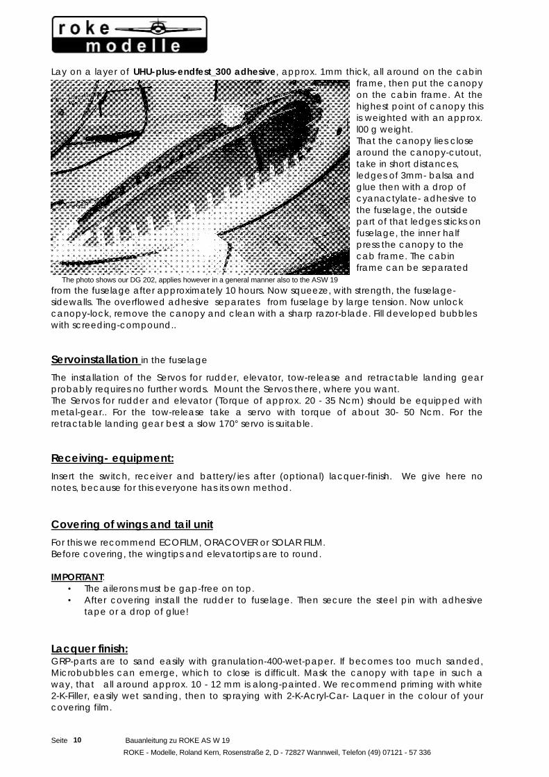
Lay on a layer of UHU-plus-endfest_300 adhesive, approx. 1mm thick, all around on the cabin frame, then put the canopy on the cabin frame. At the highest point of canopy this is weighted with an approx. l00 g weight. That the canopy lies close around the canopy-cutout, take in short distances, ledges of 3mm- balsa and glue then with a drop of cyanactylate- adhesive to the fuselage, the outside part of that ledges sticks on fuselage, the inner half press the canopy to the cab frame. The cabin frame can be separated
from the fuselage after approximately 10 hours. Now squeeze, with strength, the fuselage-sidewalls. The overflowed adhesive separates from fuselage by large tension. Now unlock canopy-lock, remove the canopy and clean with a sharp razor-blade. Fill developed bubbles with screeding-compound.. Servoinstallation in the fuselage
The installation of the Servos for rudder, elevator, tow-release and retractable landing gear probably requires no further words. Mount the Servos there, where you want. The Servos for rudder and elevator (Torque of approx. 20 - 35 Ncm) should be equipped with metal-gear.. For the tow-release take a servo with torque of about 30- 50 Ncm. For the retractable landing gear best a slow 170° servo is suitable. Receiving- equipment:
Insert the switch, receiver and battery/ies after (optional) lacquer-finish. We give here no notes, because for this everyone has its own method.
Covering of wings and tail unit
For this we recommend ECOFILM, ORACOVER or SOLAR FILM. Before covering, the wingtips and elevatortips are to round. IMPORTANT:
• The ailerons must be gap-free on top. • After covering install the rudder to fuselage. Then secure the steel pin with adhesive
tape or a drop of glue! Lacquer finish: GRP-parts are to sand easily with granulation-400-wet-paper. If becomes too much sanded, Microbubbles can emerge, which to close is difficult. Mask the canopy with tape in such a way, that all around approx. 10 - 12 mm is along-painted. We recommend priming with white 2-K-Filler, easily wet sanding, then to spraying with 2-K-Acryl-Car- Laquer in the colour of your covering film.
The photo shows our DG 202, applies however in a general manner also to the ASW 19

Bauanleitung zu ROKE AS W 19 Seite
ROKE - Modelle, Roland Kern, Rosenstrasse 2, D - 72827 Wannweil, Telefon 0049 7121 - 57 336
11
Balancing: (Center of gravity / C.G. C.G. = 75 to 85 mm behind wing-leading-edge (Depending upon personal flight style). The optimal Dihedral is about 1,3 °. Raise the model at the C.G. under the wing. The tail boom (the fuselage behind the wing) is to lie with the upper edge horizontally.
First flight:
start at a slope or by aerotowing against the wind. The model wins height in the gentle climb . In safety-height you make yourselves familiar with the rudders. Trim the Model for best gliding.
Spoiler effect:
If in the flight the spoilers are fully driven out, the model goes on the nose. If you do not steer against with the elevator, the model changes after some time into the dive. Thus watch !!! Mixing of the elevator to the spoiler is ideal function from approx. 3 to 10%. If you have possibility, use it!. By the way, the spoilers in the approach flight have as strong effect as with the original, thus sensitivly to proportionDrive out at ground level the spoilers max. 50%. Spoiler permit very high rates of descent. The speed will not automatically less, but has to be pulled away with the elevator. Additionally to spoilers can also still the ailerons be raised. This allows very precise and slow landings on the point. Therefor the ailerons are put up to 40°, which requires however then also a reduction of the elevator admixture. In extreme cases, even depth rudder mixing can be necessary. Find these adjustments yourself, when flying. Rolls, inverted flight, loopings and turns are possible with the model. Most beautifully however are quick past flights in small height and thermal gliding for hours up to the neck rigidity. You will experience it. Still something when landing: approach far, the gliding angle are outstanding!
Safety references: Model airplane flying with remote controlled models is a fascinating hobby. But as with many other things the adherence to certain guidelines is the condition for a safe and troublefree operation.
In particular flight models, in addition, fast auto and ship's models can cause damages to property or, still more badly, personal injuries.
Consider therefore the following safety guidelines and accomplish the aforementioned safety-checks in regular intervals.
Consider when building:
• All rudder deflections and linkages must be implemented in such a way, that the rudders can be easily moved. Keep the play as small as possible.
• Protect Receiver, batteries and Servos against vibrations.
• do not stretch cables or bend closely!

Seite Bauanleitung zu ROKE AS W 19
ROKE - Modelle, Roland Kern, Rosenstraße 2, D - 72827 Wannweil, Telefon (49) 07121 - 57 336
12
• Do not lead receiver antenna parallel to metal linkages.
• If your fuselage is metallic-lacquered, or a fuselage, that was made from carbon fiber, shift the receiver antenna outside of the fuselage.
• Avoid electrical crack-impulses (metal on metal).
• Prevent disturbances, caused by static loading, electrical ignition etc. by suitable shielding and spark-suppression.
Check the model regularly for...
• Linkage and rudders with low-friction and free from play.
• Stability and perfect condition of linkages, linking and hinges
• Breaks, tears, abraded positions etc..
• Cable and connectors on perfect condition and reliability of electrical contact.
Before flight:
• Transmitter- and receivers-batteries Charge carefully , charge examine.
• At the airfield you contact the flight-controller and announce your frequency, and co-ordinate with other pilots.
• Test the Range of your RC-equipment with pushed in antenna.
• Examine function of all rudders and secondary functions.
• If irregularities arise, don´t start to fly. Look for the errors, eliminate, control again.
During the flight:
• If you do not have flight experience, ask an experienced model pilot for help. The training with teacher/pupil-cable is best at the beginning.
• Do not fly over persons , also not in low height directly to them.
• Don´t fly risky maneuvers.
• If you determine arising disturbances, immediately terminate your flight.
• Replace defective parts only with original parts. Don´t try to repair remote control or their parts. Let repairs from authorized workshops accomplish. Ask your dealer for addresses of services stations.
• With attention of these references you fulfill the most important conditions for safe flying of your model. We wish you much joy thereby.
Bauanleitung zu ROKE AS W 19 Seite
ROKE - Modelle, Roland Kern, Rosenstrasse 2, D - 72827 Wannweil, Telefon 0049 7121 - 57 336
13
For your own security:
Examine after not-airfield-landings and hard landings immediately the model for visible and covered damage. If you´re not sure, that everything is correct, please stop flying and call us for advice.!
ROKE - Modelle Telephone 0049 7121 - 57 336 Roland Kern FAX 0049 7121 - 54 439 Rosenstrasse 2 D- 72827 Wannweil
Office hours Mon, Tuesday, Thursday and Friday 10:00- 12:30 / 14:30- 18:00 o'clock
Saturday 9:30 – 12:30 o'clock
On Wednesdays according to agreement
For emergencies not during the office hours ask for our D 2 - telephone number at international-phone-information..