standard 1/3 compressor pack control - · pdf file · 2017-10-20standard 1/3...
TRANSCRIPT
Application program for pCO
Standard 1/3 compressorpack control
Manual version: 1.0 - 21/10/94
Program code: EPSTDEFC2A
Rif.: 83EM

Ver. 1.0 dated 21/10/94 2
pCO controllerfor refrigeration
EPSTDIFC2A ver. 1.002 (normally closed inputs)
Functions performed by pCO:
- Control and regulation of a refrigeration system, max. 3 compressors
- Display of all measured values and set-points
- Possibility of selecting and successively modifying the regulation parameters
- Indication of any off-normal condition via acoustic and visual signals (BUZZER and ALARM MESSAGES)
- USER-UNIT communication interface (KEYPAD - DISPLAY - LED INDICATORS)
- Possible connection to remote supervisor via RS422 serial line.
Manuale Firma responsabile:
Versione 1.0 Data: 21/10/1994 Pagg. 37
Ver. 1.0 dated 21/10/94 3
Contents
pCO .....................................................................................................................4Main card ....................................................................................................4Terminal......................................................................................................5Configuration of pCO ..................................................................................6User Interface .............................................................................................6Inputs/Outputs ............................................................................................8Optional Cards and Eprom........................................................................11Before requesting Service.........................................................................12The program .............................................................................................13Software Initialization ................................................................................14Configuring pCO .......................................................................................15Using pCO ................................................................................................18
Mask Tree .........................................................................................................22General features .......................................................................................23MENU Masks ............................................................................................23INFO Masks..............................................................................................25
MAINTENANCE Masks ......................................................................26I/O Masks..................................................................................................28
CLOCK Masks ...................................................................................29SET-POINT Masks ...................................................................................30PROG Masks ............................................................................................31PROG+MENU Masks................................................................................34ALARM Masks ..........................................................................................36

Ver. 1.0 dated 21/10/94 4
pCO
The figure below shows all the components and optional devices of pCO dedicated to the controland regulation of refrigeration units.
Main card
The microprocessor-based main card is theintelligent part of the system since it carries outthe regulation program. It comes complete withterminals dedicated to the connection of the maindevices (eg. valves, compressors, fans). Thesoftware is contained in the Eprom whereas allparameters set by the User will be permanentlystored (also in the event of power source failure)into the EEprom.The main card can be connected to the Rs422serial line so as to providesupervisory/telemaintenance services (standardRS422 and Carel communication protocol).
NO11
C11
NC11
VG2
VG1
Y2
Y1B1
AVSS
B2
B3
B4
B5
B6
AVSS
AVSS
J14J15
G
G0
ID11R
ID11
ID12R
ID12
NO10
C10
NC10
NO9
C9
NC9
NO8
C8
NO7
C7
NO6
C6
NO13
C13
RS422
B8
B7
+24
IDCM2
ID10
ID9
ID8
ID7
ID6
IDCM1
ID5
ID4
ID3
ID2
ID1
NO12
C12
NO5
C5
NO4
C4
NO3
C3
NO2
C2
NO1
C1

Ver. 1.0 dated 21/10/94 5
Terminal
The terminal unit - managed by the microprocessor - comes complete with display, keypad and ledindicators. Setting the main control parameters (set-points, differential, alarm thresholds) andperforming any other operation is extremely simple.The terminal unit must be connected to the main card only when programming the instrument; afterthat, the two units can be disconnected.The terminal unit enables you to perform the following operations:
• initial programming via password;• possibility of modifying run-time any working parameter;• display of any alarm condition (via alarm messages and buzzer);• display of all measured values.
menu I/O set prog
info? on-off alarm enter
Terminal unit with open front panel lid

Ver. 1.0 dated 21/10/94 6
Configuration of pCO
The figure below shows the hardware architecture of pCO.
c
d
e f
g
i
j
h
Description of the components
1. Rubber keypad2. LCD display, 4 x 203. Polycharbonate front panel and front lid4. Connector for 24 Vac 50/60 Hz 15 VA power source or 24 Vdc 10 W5. Telephone connector for connection to terminal unit6. Clock card (optional)7. Program Eprom8. RS422 card for serial line connection to supervisory/telemaintenance systems

Ver. 1.0 dated 21/10/94 7
User Interface
Display
The Liquid Crystal Display shows the values of the controlled variables, selected set-points, alarmthresholds and any other information concerning the status of the unit. In the event of an off-normalcondition, a special alarm message will appear on the display.
Keypad
pCO comes complete with a 15 button keypad. Keypad and display represent the User Interface.Each button has a specific function, as listed below:
ON / OFF Operates and stops compressors and fans.
ALARM Goes to the first active alarm mask and turns off the buzzer. If pressed a second time on the active alarm mask, it resets the alarm and returns to the first mask again. If you press this button and there are no active alarms, the message 'NO ACTIVE ALARM' will appear on the display. All alarm masks can be scrolled by pressing the UP and DOWN buttons.
UP & DOWN When the cursor is on the HOME position, these buttons allow you to read allthe masks of a specific section (masks are organized in a loop structure). When the cursor is within a numeric field, the UP & DOWN button allow youto increase and decrease the value on which the cursor is positioned. When the cursor is on a choice field, pressing these buttons allows you to display all the options available (eg. Yes/No).
ENTER When the cursor is on the selection masks, press ENTER once to move the cursor to the first introduction field. Press ENTER again to confirm the set value and to move the cursor to the next field. When the cursor reaches the last field, it will return to the HOME position again (cursor at position 0,0 on the display).
MENU Press it to go to the MENU mask.
INFO Press it to go to the M_INFO1 mask.
MAINT Press it to go to the M_MAINT1 mask.
PRINT Usable only in models with printer.
I/O Press it to go to the IN_OUT1 mask.
TIME Press it to go to the CLOCK1 mask.

Ver. 1.0 dated 21/10/94 8
SET Press it to go to the M_SET1 mask.
PRG Press PROG to prompt the password. Introduce the correct password to gain access to the M_SERVICE mask.
MENU+PROG Press and release the MENU and PROG buttons SIMULTANEOUSLY. Then, introduce the password to gain access to the CONF_MACHINE1 mask.
Led Indicators
The keypad buttons and the green led indicators are placed side by side. Any time you press abutton, the corresponding green led will light up thus making it easier to identify which masksection you are using.
When pressing the MENU+PROG buttons to gain access to the configuration parameters, it is theled indicator corresponding to the PROG button that will light up.
There are other three led indicators under the following rubber buttons:
1. ON / OFF button green led indicator - Indicates that the unit is ON.
2. ALARM button red led indicator - Indicates an alarm condition.
3. ENTER button yellow led indicator - Indicates correct power supply.
Ver. 1.0 dated 21/10/94 9
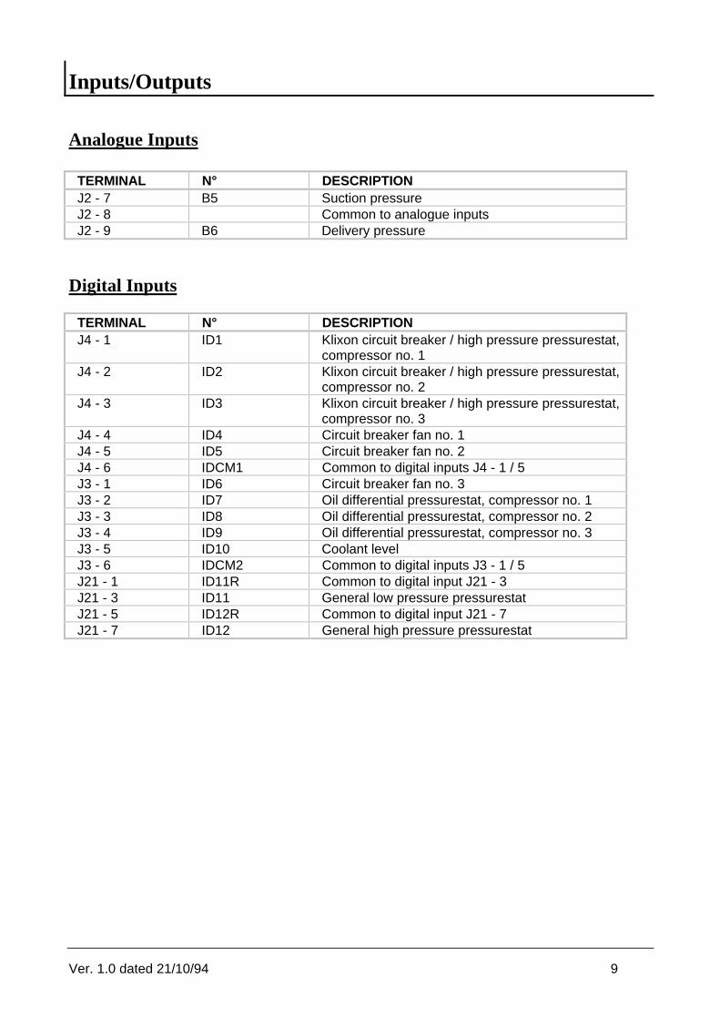
Inputs/Outputs
Analogue Inputs
TERMINAL N° DESCRIPTIONJ2 - 7 B5 Suction pressureJ2 - 8 Common to analogue inputsJ2 - 9 B6 Delivery pressure
Digital Inputs
TERMINAL N° DESCRIPTIONJ4 - 1 ID1 Klixon circuit breaker / high pressure pressurestat,
compressor no. 1J4 - 2 ID2 Klixon circuit breaker / high pressure pressurestat,
compressor no. 2J4 - 3 ID3 Klixon circuit breaker / high pressure pressurestat,
compressor no. 3J4 - 4 ID4 Circuit breaker fan no. 1J4 - 5 ID5 Circuit breaker fan no. 2J4 - 6 IDCM1 Common to digital inputs J4 - 1 / 5J3 - 1 ID6 Circuit breaker fan no. 3J3 - 2 ID7 Oil differential pressurestat, compressor no. 1J3 - 3 ID8 Oil differential pressurestat, compressor no. 2J3 - 4 ID9 Oil differential pressurestat, compressor no. 3J3 - 5 ID10 Coolant levelJ3 - 6 IDCM2 Common to digital inputs J3 - 1 / 5J21 - 1 ID11R Common to digital input J21 - 3J21 - 3 ID11 General low pressure pressurestatJ21 - 5 ID12R Common to digital input J21 - 7J21 - 7 ID12 General high pressure pressurestat

Ver. 1.0 dated 21/10/94 10
Digital Outputs
TERMINAL N° DESCRIPTIONJ5 - 4 / J5 - 5 1 - NO1 / C1 Compressor no. 1J5 - 1 / J5 - 2 2 - NO2 / C2 Compressor no. 2J6 - 10 / J6 - 11 3 - NO3 / C3 Compressor no. 3J6 - 7 / J6 - 8 4 - NO4 / C4 Fan no. 1J6 - 4 / J6 - 5 5 - NO5 / C5 Fan no. 2J24 - 7 / J24 - 8 6 - NO6 / C6 Fan no. 3J24 - 4 / J24 - 5 7 - NO7 / C7 Unit onJ22 - 5 / J22 - 6 10 - NO10 / C10 Delayed general alarmJ22 - 1 / J22 - 2 11 - NO11 / C11 General alarm
Analogue Outputs
TERMINAL N° DESCRIPTIONJ20 - 1 / 4 Y1 Fans Inverter
Relay outputs layout
c1NO1
c2NO2
c3NO3
Contactor compressor 1
Contactor compressor 2
Contactor compressor 3
c4NO4
c5NO5
c6NO6
Contactor fan 1
Contactor fan 2
Contactor fan 3
c7NO7
Delayed Alarm
24 / 220 Volt
c10
NO10
Unit on
c11
NO11 Alarm
Ver. 1.0 dated 21/10/94 11
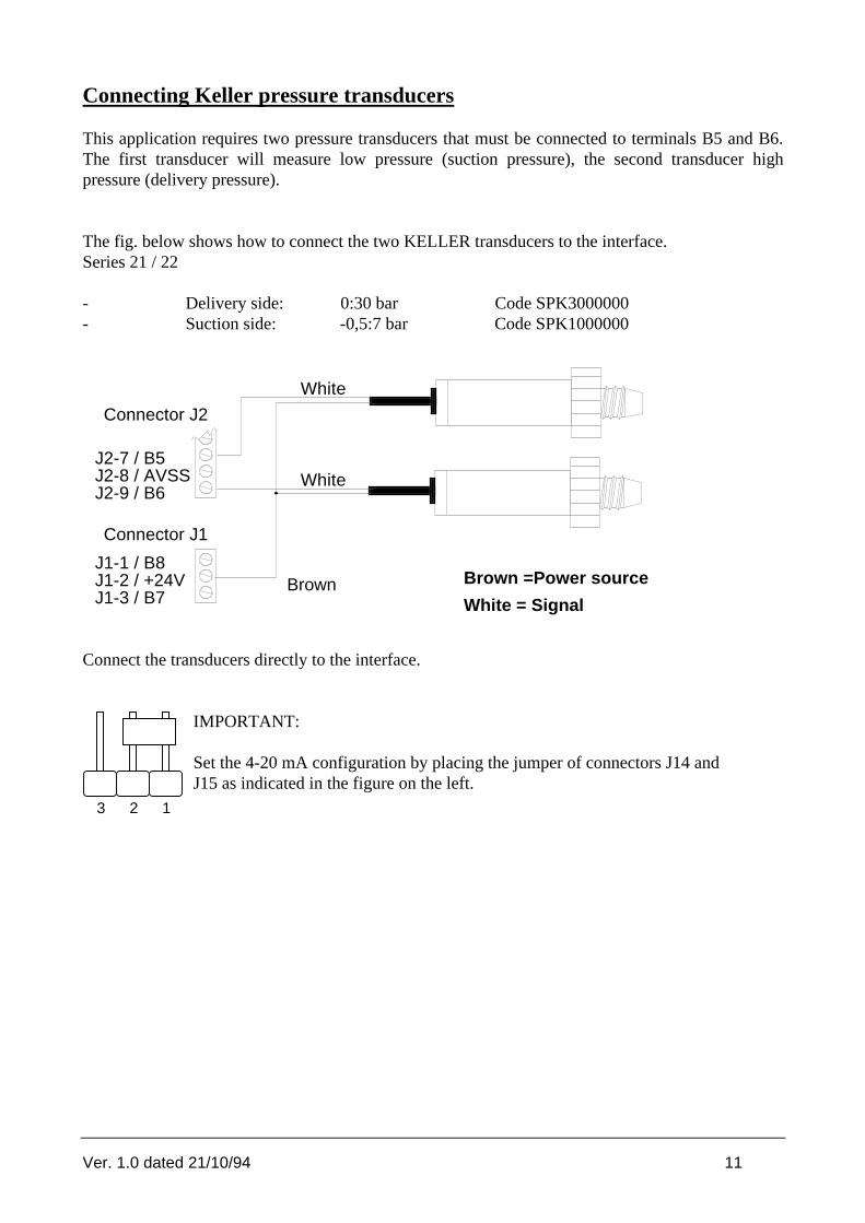
Connecting Keller pressure transducers
This application requires two pressure transducers that must be connected to terminals B5 and B6.The first transducer will measure low pressure (suction pressure), the second transducer highpressure (delivery pressure).
The fig. below shows how to connect the two KELLER transducers to the interface.Series 21 / 22
- Delivery side: 0:30 bar Code SPK3000000- Suction side: -0,5:7 bar Code SPK1000000
White
Brown Brown =Power source
White = Signal
J2-7 / B5J2-8 / AVSSJ2-9 / B6
Connector J2
J1-1 / B8J1-2 / +24VJ1-3 / B7
Connector J1
White
Connect the transducers directly to the interface.
IMPORTANT:
Set the 4-20 mA configuration by placing the jumper of connectors J14 andJ15 as indicated in the figure on the left.
3 2 1

Ver. 1.0 dated 21/10/94 12
Optional Cards and Eprom
Clock Card
Clock CardThe clock card - necessary to display current time and date - must bedirectly inserted into the main card through a plug-in connector. The clockcard is necessary to provide a time-zones control action. In the event ofpower supply failure to pCO, the clock card will be powered by a lithiumbattery for more than one month. For connection to the relative connector(6) see page 4 above.Code MNEWCLOCK0
RS422 Serial CardThe RS422 serial card allows pCO to be network connected into local orremote supervisory and telemaintenance systems. For connection to therelative connector (8) see page 4 above.
Mounting the EpromThe Eprom - separately supplied - contains the application program.
When inserting the eprom into its socket (see page 4) pay attention to align its polarity correctly (thenotch on the eprom must coincide with that of the socket). Insert the eprom carefully withoutbending or breaking its small pins.

Ver. 1.0 dated 21/10/94 13
Before requesting Service
THE UNIT DOES NOT STARTLed indicator (power on) OFF, Lcd off, other led indicators off.
Cause:a. no mains voltageb. transformer (220 - 24V) is not powered with 24 Vacc. 24V power supply connector is not well plugged-in
THE UNIT IS ON BUT:the alarm led indicator is ONthe LCD shows no messages or random messagesthe buzzer sounds
Cause:a. eprom inserted with wrong polarityb. pins of the eprom bentc. microprocessor chip damaged: contact qualified service personnel
WRONG INPUT SIGNALS READING
Cause:a. incorrect probe connectionsb. probes' wires must be placed far from electrical noises (power cables, contactors, high tension cables, etc.)c. incorrect connection between interfaces and controller (flat cables)d. incorrect power source to interfaces and probes
FAULTY EEPROM
a. contact qualified service personnel
pCO turns Off and On repeatedly (watch-dog) or it operates some (digital and/or analogue) outputsat random.
Cause:a. incorrect connections between interfaces and controllerb. power cables are too close to the microprocessors of the interfaces and to the control card.

Ver. 1.0 dated 21/10/94 14
The program
General description
pCO by Carel has been specifically designed to control and regulate refrigeration units with 1 to 3compressors as well as 1 to 3 condensation-removal fans. The activation of the compressorsdepends on the value measured by the suction trnasducer and on the selected set-point; theactivation of the fans depends on the delivery pressure value.The control of the pressure is based on a 'neutral zone regulation' that minimizes the changes ofpressure thus balancing the entire system. The system includes 12 digital inputs for the detection ofalarm signals. In case of off-normal condition, the interested device will be stopped and theOperator will be alerted by the buzzer and by a red led indicator placed on the front panel of theinstrument.Alarm, pressure and set-point messages are freely accessible whereas setting the workingparameters requires the introduction of a key word so as to prevent unauthorized access to theregulation data. It is possible to display a wide range of message masks by simply acting on thekeypad (eg. clock masks and pCO identification number, necessary to enable supervisory serviceswithin a local network). Access to the reserved masks requires a password (1234). These specialmasks contain the main working parameters of the system, eg. number of compressors, number offans, times, alarm thresholds, etc.The configuration masks - accessible via password only - afford you a special procedure wherebyyou can initialize pCO with factory-set parameters, making the configuration of the entire systemeven faster and easier.
Finally, remember that pCO can be easily connected to a SUPERVISORY COMPUTER for thecentralized control of any normal and off-normal condition of the system.

Ver. 1.0 dated 21/10/94 15
Software Initialization
Initializing the software means to set a series of important parameters such as:
- number of compressors and fans- control parameters (set-points, times, alarm thresholds, etc.)
All set data are permanently stored and retrieved any time pCO is turned ON. The very first timepCO is turned ON, we recommend cancelling the original data since they might be unsuitable foryour application requirements and then loading the factory-set parameters so as to make theinitialization procedure fast and easy.Follow these indications:
- Turn pCO ON. After a few seconds the main mask - MENU MASK - appears on the display.When starting pCO the very first time, ignore any alarms since they probably result from incorrect data.
- Press MENU + PRG simultaneously. Now you have to digit the password, necessary to prevent unauthorized access to the operational parameters (configuration section).
- Digit the correct password. After that the configuration masks can be accessed. Use the UP & DOWN buttons to reach the CONF_MACHINE7 mask allowing you to delete the back-upmemory and automatically set the entire range of factory-set values.
If some standard values do not suit your application requirements, just change them by entering thededicated selection mask/s.
- ¹ MANUFACTURER password: "1234" . We recommend keeping the password secret so asto prevent unauthorised access to the operational parameters. The Manufacturer password can be used when performing preliminary operations as well as any time you do not manage to gain access to the configuration mask by the SERVICE password in the CONF_MACHINE6 mask.

Ver. 1.0 dated 21/10/94 16
Configuring pCO
Number of compressors
You can select the number of compressors to be controlled directly through the maskCONF_MACHINE1. pCO manages 1 to 3 compressors having the same capacity as well as theirshifts.
Number of fans
You can select the number of fans to be controlled directly through the mask CONF_MACHINE2.pCO manages 1 to 3 fans and their shifts.
Optional devices
You can enhance the functions of the pCO controller by adding a series of optional devices (clockcard, RS422 serial card) that can be enabled by simply acting on the dedicated masks.
In order to enable the clock card it is necessary to set time and date in the dedicated mask. WhenpCO is network-connected into a supervisory/telemaintenance system by means of the RS422 serialcard, it is necessary to give each pCO a specific identification number so as to address messagescorrectly.
When giving each pCO its identification number,- do NOT give different pCOs the same address (each pCO must have its own identification
number);
- the addresses of the pCOs belonging to the same serial line must be consecutive, starting from no. 1.
Supervisor
The table below lists the variables pCO tramsits to the supervisory computer when network-connected into a centralized system.
MEANING TYPE IN/OUTStatus of compressor no. 1/3 Digital On dispalyStatus of fan no. 1/3 Digital On dispalyStatus of the system Digital selectableKlixon 1/3 circuit breaker (alarm) Digital On dispalyAlarm: oil differential pressurestat 1/3 Digital On dispalyAlarm: general high pressure (pressurestat) Digital On dispalyAlarm: general low pressure (pressurestat) Digital On dispalyCoolant level alarm Digital On dispalyAlarm: circuit breaker fan no. 1/3 Digital On dispalyAlarm: exceeded hours threshold of compressor no. 1/3 Digital On dispalyAlarm: high delivery pressure Digital On dispaly

Ver. 1.0 dated 21/10/94 17
Alarm: high suction pressure Digital On dispalyAlarm: suction probe broken or disconnected Digital On dispalyAlarm: delivery probe broken or disconnected Digital On dispalyAlarm: clock card broken or disconnected Digital On dispalyAlarm: eeprom damaged Digital On dispalyAlarm: low suction pressure Digital On dispalyGeneral alarm Digital On dispalyBuzzer off / alarm reset (like ALARM button) Digital SelectableCall supervisor Digital SelectableSuction pressure Analogue On displayDelivery pressure Analogue On displayCompressors set-point Analogue selectableCompressors differential Analogue selectableAlarm threshold: low suction pressure Analogue selectableAlarm threshold: high suction pressure Analogue selectableAlarm threshold: high delivery pressure Analogue selectableFans set-point Analogue selectableFans differential Analogue selectableON routine of the compressors Analogue On displayOFF routine of the compressors Analogue On displayNumber of compressors Integer SelectableNumber of fans Integre SelectableSetting the hour Integer SelectableSetting minutes Integer SelectableCurrent hour Integer On displayCurrent minutes Integer On displayTime to call the supervisor (set the hour) Integer SelectableTime to call the supervisor (set the minutes) Integer SelectableCompressors hours threshold Integer On displayWorking hours of compressor no. 1/3 Integer On display

Ver. 1.0 dated 21/10/94 18
Using pCO
Status of the system
The system can be ON, OFF or in the MANUAL functioning mode.
- It is possible to turn ON the refrigeration unit by pressing the ON button on the keypad or - in case of network connection to a centralized computer - by means of the external commandoperated by the supervisor. When the system is ON, compressors and fans will will be operated on the basis of the values measured by the pressure transducers.
- To turn the system off, press the OFF button on the keypad (this function must be enabled through the CONF_MACHINE4 mask) or send the 'off' command from the supervisor. In the event of low pressure alarm (broken probe), the system will automatically turn off. This function, however, must be previously enabled through the CONF_MACHINE4 mask. When the system is Off, all connected devices will turn Off.
- To activate the manual procedure, act on the masks M_MAINT6 and M_MAINT7 (protected by password). The manual procedure forces the unit into the Off status so that it will be possible to operate all connected devices manually, with the exception of the pressure control action and all alarm conditions that will be always automatically detected.
Compressors
The regulation action is based on a 'neutral zone control': when the pressure value goes below theset-point the compressors will be stopped, when the pressure exceeds the value given to set-point +differential, the compressors will be activated. Set differential and set-point in the dedicated mask.
stopcompressors
startcompressors
PRESSIONSUCTIONSET
POINT
DIFFERENTIALWhen the pressure value ranges between the set-point and the set-point + differential zone, thesystem will be under stable conditions (neutral zone) and there won't be any requests forcompressors ON/OFF.
Ver. 1.0 dated 21/10/94 19
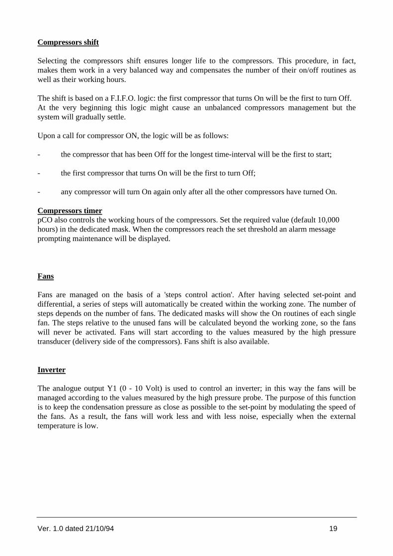
Compressors shift
Selecting the compressors shift ensures longer life to the compressors. This procedure, in fact,makes them work in a very balanced way and compensates the number of their on/off routines aswell as their working hours.
The shift is based on a F.I.F.O. logic: the first compressor that turns On will be the first to turn Off.At the very beginning this logic might cause an unbalanced compressors management but thesystem will gradually settle.
Upon a call for compressor ON, the logic will be as follows:
- the compressor that has been Off for the longest time-interval will be the first to start;
- the first compressor that turns On will be the first to turn Off;
- any compressor will turn On again only after all the other compressors have turned On.
Compressors timerpCO also controls the working hours of the compressors. Set the required value (default 10,000hours) in the dedicated mask. When the compressors reach the set threshold an alarm messageprompting maintenance will be displayed.
Fans
Fans are managed on the basis of a 'steps control action'. After having selected set-point anddifferential, a series of steps will automatically be created within the working zone. The number ofsteps depends on the number of fans. The dedicated masks will show the On routines of each singlefan. The steps relative to the unused fans will be calculated beyond the working zone, so the fanswill never be activated. Fans will start according to the values measured by the high pressuretransducer (delivery side of the compressors). Fans shift is also available.
Inverter
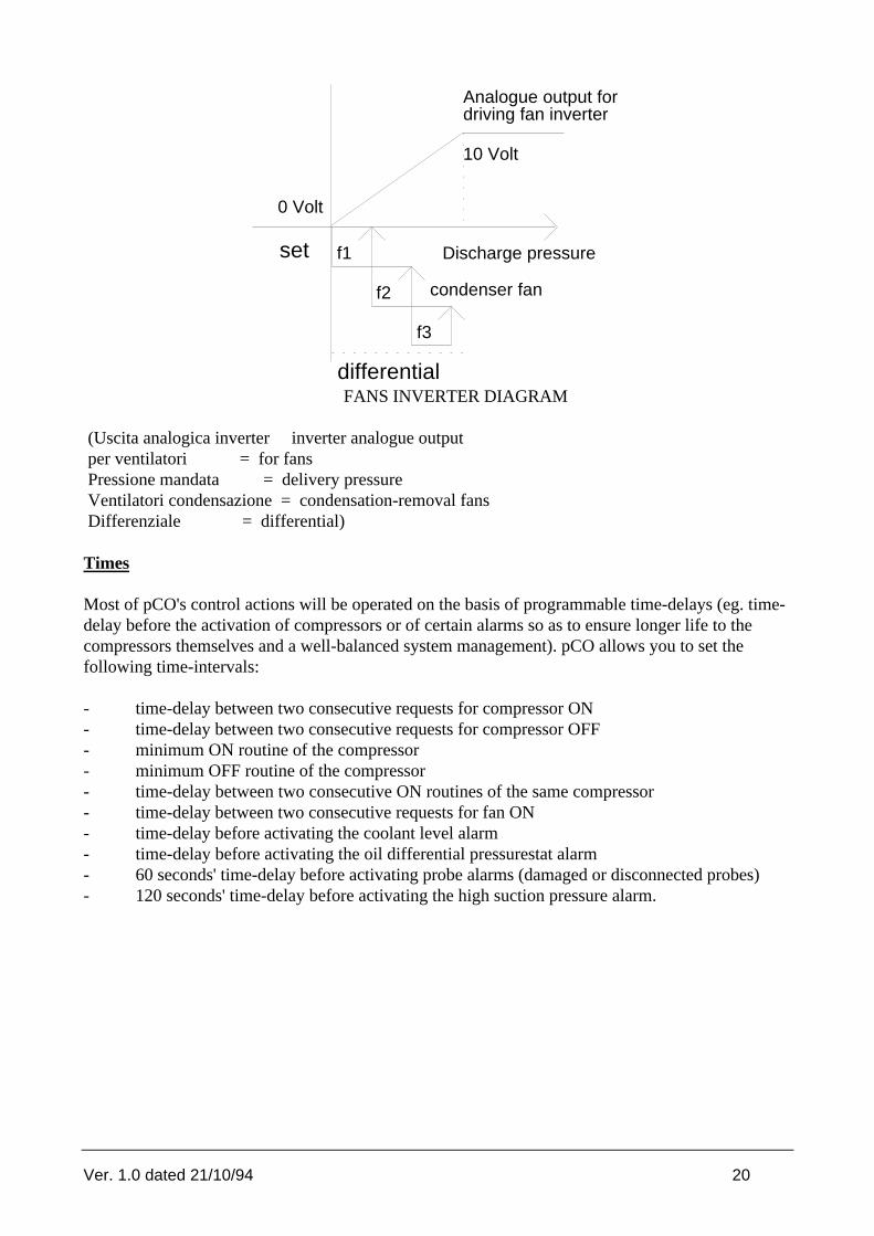
The analogue output Y1 (0 - 10 Volt) is used to control an inverter; in this way the fans will bemanaged according to the values measured by the high pressure probe. The purpose of this functionis to keep the condensation pressure as close as possible to the set-point by modulating the speed ofthe fans. As a result, the fans will work less and with less noise, especially when the externaltemperature is low.
Ver. 1.0 dated 21/10/94 20
set
differential
f1
f2
f3
Discharge pressure
0 Volt
10 Volt
Analogue output fordriving fan inverter
condenser fan
FANS INVERTER DIAGRAM
(Uscita analogica inverter inverter analogue output per ventilatori = for fans Pressione mandata = delivery pressure Ventilatori condensazione = condensation-removal fans Differenziale = differential)
Times
Most of pCO's control actions will be operated on the basis of programmable time-delays (eg. time-delay before the activation of compressors or of certain alarms so as to ensure longer life to thecompressors themselves and a well-balanced system management). pCO allows you to set thefollowing time-intervals:
- time-delay between two consecutive requests for compressor ON- time-delay between two consecutive requests for compressor OFF- minimum ON routine of the compressor- minimum OFF routine of the compressor- time-delay between two consecutive ON routines of the same compressor- time-delay between two consecutive requests for fan ON- time-delay before activating the coolant level alarm- time-delay before activating the oil differential pressurestat alarm- 60 seconds' time-delay before activating probe alarms (damaged or disconnected probes)- 120 seconds' time-delay before activating the high suction pressure alarm.

Ver. 1.0 dated 21/10/94 21
COMPRESSOR1
COMPRESSOR1
COMPRESSOR1
Minimum running time
on
off
Minimum "off" time
on
off
on
off
Interval between two successive starts of same compressor
on
off
on
off
on
off
off
on
on
off
off
on
COMPRESSOR1
COMPRESSOR2
COMPRESSOR1
COMPRESSOR2
Interval between starts of different compressors
Interval between stops of different compressor
Time-zones
The time-zone control action proves to be an extremely useful option allowing pCO to work with alower set-point during certain periods of the day and above all during the night, so as to avoidwasting energy. pCO has programmable time-zones. All you have to do is just set them (hour andminutes) and their relative set-points. The table below shows the working logic of a time-zonecontrol action.Eg:HOUR/MINUTE SETPOINT EFFECT06:00 0,9 bar from 06:00 to 07:00 set-point = 0,9 bar07:00 1 bar from 07:00 to 10:00 set-point = 1 bar10:00 1,1 bar from 10:00 to 17:00 set-point = 1,1 bar17:00 0,8 bar from 17:00 to 6:00 set-point = 0,8 bar
TIME
SETPOINT 0
0,20,40,60,8
11,2
6.00 7.00 10.00 17.00
0,91
1,1
19.126.00
7.00
10.00
17.00
In order to set time-zones, it is necessary to provide pCO with a clock card. It is possible to programup to 4 time-zones. Should you need less than 4, it is necessary to give the unused time-zones thesame values.The table below shows RIGHT and WRONG settings when using only TWO time-zones.

Ver. 1.0 dated 21/10/94 22
WRONG RIGHTHOUR/MINUTES SETPOINT ORE/MINUTI SETPOINT07:30 1 bar 07:30 1 bar18:00 0,8 bar 18:00 0,8 bar00:00 0 18:00 0,8 bar00:00 0 18:00 0,8 bar
All time-zones can be programmed according to your application requirements; if you do not selectany time-zone and relative set-point, the reference set-point will be that set through the M_SET1mask.
Default values
Default values can be automatically loaded through the 'DEFAULT' mask. The table belowindicates a list of default parameters (1st column), the mask where you can set/modify their value(2nd column) and the default value given to each specific parameter (3rd column).
PARAMETER MASk VALUENumber of compressors CONF_MACCHINA1 3Compressors shift enabled CONF_MACCHINA1 yesNumber of fans CONF_MACCHINA2 3Fans shift enabled CONF_MACCHINA2 yesHigh pressure probe min. limit CONF_MACCHINA3 0 barHigh pressure probe max. limit CONF_MACCHINA3 30 barLow pressure probe min. limit CONF_MACCHINA3 -0,5 barLow pressure probe max. limit CONF_MACCHINA3 7 barButton OFF enabled CONF_MACCHINA4 yesUnit turns OFF in the event of low pressure probe failure CONF_MACCHINA4 NoAutostart CONF_MACCHINA5 yesHigh pressure threshold (delivery side) M_SERVIZIO 20 barHigh pressure threshold (suction side) M_SERVIZIO 3 barLow pressure threshold (suction side) M_SERVIZIO1 0 barOil differential alarm delay M_SERVIZIO2 120 sCoolant level alarm delay M_SERVIZIO2 90 sRelay energization delay (alarm no. 16) M_SERVIZIO3 600 sTime-delay between consecutive requests for compressors ON M_SERVIZIO4 20 sTime-delay between consecutive requests for compressors OFF M_SERVIZIO4 10 sCompressors' min. ON routine M_SERVIZIO5 60 sCompressors' min. OFF routine M_SERVIZIO5 180 sMin. time-interval between 2 consecutive ON routines of the samecompressor
M_SERVIZIO6 360 sec
Time-delay between ON routines of different fans M_SERVIZIO7 2 secCompressors set-point M_SET1 1 barCompressors differential M_SET1 0,5 barFans set-point M_SET2 15,5 barFans differential M_SET2 1,5 barCompressors max. threshold M_MANUT3 10.000 hour

Ver. 1.0 dated 21/10/94 23
Mask Tree
General features
+--------------------+¦x RAW0 AL¦¦HOME RAW1 ¦¦ RAW2 ¦| RAW3 ¦+--------------------+
In the event of off-normal conditions, the 'AL' message flashes on the right-hand corner of thedisplay. The left-hand corner of the display represents the 'HOME' position.
+--------------------+¦ ¦¦ - WAIT - ¦¦ DATA READING ¦| ¦+--------------------+
This mask appears when you turn On the system. After about 5 seconds the main mask -MENU_MASK - will be displayed.
You can display pCO's masks by pressing the dedicated buttons on its front panel keypad (See'Keypad' above).

Ver. 1.0 dated 21/10/94 24
MENU Masks
MENU_MASK+--------------------+¦00/00/0000 00:00 AL¦¦In Pres. 00.0 bar¦¦Out Pres. 00.0 bar¦¦UNIT OFF *¦+--------------------+
This mask shows the values measured by the transducers. The second row indicates the lowpressure value relative to the suction side of the compressor, the third row indicates the highpressure value (relative to the delivery side of the compressor).
MENU_MASK1+--------------------+¦Neutral zone AL¦¦Compressors ¦¦Insertions 00.0 bar¦¦Stop 00.0 bar¦+--------------------+
This mask indicates the limit values of the neutral zone: the first row indicates the suction pressurevalue above which there is a request for compressor ON, the third row shows the suction pressurevalue under which one of the compressor will be forced to stop.
MENU2_MASK+--------------------+¦ On Of AL¦¦Step 1 00.0 00.0 ¦¦Step 2 00.0 00.0 ¦¦Step 3 00.0 00.0 ¦+--------------------+
This mask shows the values which determine the ON and OFF routines of the fans' steps.

Ver. 1.0 dated 21/10/94 25
INFO Masks
M_INFO1+--------------------+¦00/00/0000 00:00 AL¦¦ C.AR.EL. ¦¦ REFRIGERATION UNIT ¦¦ CONTROL BT ¦+--------------------+
The first row of this mask shows date (day/month/year) and time (hour/minute) and - in case of off-normal condition - an alarm message. This mask can be customized, depending on the type ofrefrigeration unit pCO will control. To change LT (Low Temperature) into HT (High Temperature)just press the ENTER button and then act on the UP or DOWN keys.
M_INFO2+--------------------+¦CAREL STANDARD AL¦¦COD. EPSTDEFC2A ¦¦Ver. 1.012 - ZAG ¦¦June 06 1994 ¦+--------------------+
The mask above shows the code of the eprom, as well as the program's version and date.
M_INFO3+--------------------+¦Test AL¦¦date: 00/00/00 ¦¦Refrigerant = R12 ¦¦ ¦+--------------------+
This mask allows you to set the time of the general test as well as the type of refrigerant the systemrequires.
Ver. 1.0 dated 21/10/94 26
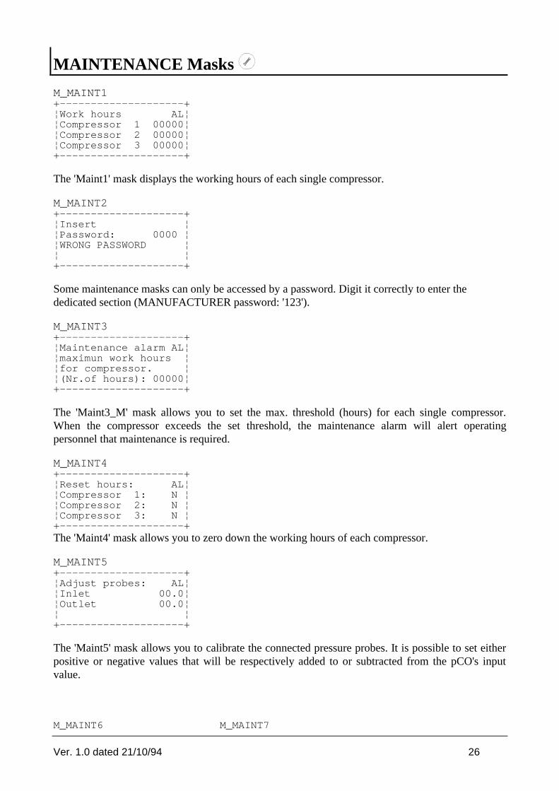
MAINTENANCE Masks
M_MAINT1+--------------------+¦Work hours AL¦¦Compressor 1 00000¦¦Compressor 2 00000¦¦Compressor 3 00000¦+--------------------+
The 'Maint1' mask displays the working hours of each single compressor.
M_MAINT2+--------------------+¦Insert ¦¦Password: 0000 ¦¦WRONG PASSWORD ¦¦ ¦+--------------------+
Some maintenance masks can only be accessed by a password. Digit it correctly to enter thededicated section (MANUFACTURER password: '123').
M_MAINT3+--------------------+¦Maintenance alarm AL¦¦maximun work hours ¦¦for compressor. ¦¦(Nr.of hours): 00000¦+--------------------+
The 'Maint3_M' mask allows you to set the max. threshold (hours) for each single compressor.When the compressor exceeds the set threshold, the maintenance alarm will alert operatingpersonnel that maintenance is required.
M_MAINT4+--------------------+¦Reset hours: AL¦¦Compressor 1: N ¦¦Compressor 2: N ¦¦Compressor 3: N ¦+--------------------+The 'Maint4' mask allows you to zero down the working hours of each compressor.
M_MAINT5+--------------------+¦Adjust probes: AL¦¦Inlet 00.0¦¦Outlet 00.0¦¦ ¦+--------------------+
The 'Maint5' mask allows you to calibrate the connected pressure probes. It is possible to set eitherpositive or negative values that will be respectively added to or subtracted from the pCO's inputvalue.
M_MAINT6 M_MAINT7

Ver. 1.0 dated 21/10/94 27
+--------------------+ +--------------------+¦Manual procedure AL¦ ¦Manual procedure AL¦¦Comp. 1: AUTOMATIC ¦ ¦Vent. 1: AUTOMATIC ¦¦Comp. 2: AUTOMATIC ¦ ¦Vent. 2: AUTOMATIC ¦¦Comp. 3: AUTOMATIC ¦ ¦Vent. 3: AUTOMATIC ¦+--------------------+ +--------------------+
Should your system require maintenance, you can use the manual function to check the status ofeach single device connected to pCO (compressors and fans). In this way you can directly operateany device ignoring their previously set time-delays . In the event of off-normal conditions duringthe manual stage, the relative alarms will be automatically displayed.

Ver. 1.0 dated 21/10/94 28
I/O Masks
IN_OUT1+--------------------+¦Digital inputs AL¦¦1-12 Open Close ¦¦01: CCCCC 6: CCCCC ¦¦11: CC ¦+--------------------+
The 'IN_OUT1' mask displays the status of the digital inputs numbered 1 - 12. 'C' stands for closed,'O' stands for open input.
IN_OUT2+--------------------+¦Analog inputs AL¦¦05: 00000 ¦¦06: 00000 ¦¦ ¦+--------------------+
This mask displays the status of current inputs no. 5 and 6.
IN_OUT3+--------------------+¦digital outputs AL¦¦1-11 Open Close ¦¦01: OOOOO 6: OO--O ¦¦11: O ¦+--------------------+
The 'IN_OUT3' mask displays the status of the digital outputs numbered 1-11. 'C' stands for closed,'O' stands for open input.
IN_OUT4+--------------------+¦Analog output AL¦¦01: 00000 ¦¦ ¦¦ ¦+--------------------+
This mask displays the status of the inverter analogue output.
Ver. 1.0 dated 21/10/94 29
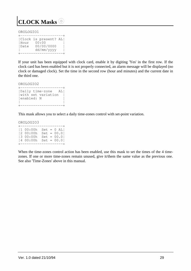
CLOCK Masks
OROLOGIO1+--------------------+¦Clock is present? AL¦¦Hour 00:00 ¦¦Date 00/00/0000 ¦¦ dd/mm/yyyy ¦+--------------------+
If your unit has been equipped with clock card, enable it by digiting 'Yes' in the first row. If theclock card has been enabled but it is not properly connected, an alarm message will be displayed (noclock or damaged clock). Set the time in the second row (hour and minutes) and the current date inthe third one.
OROLOGIO2+--------------------+¦Daily time-zone AL¦¦with set variation ¦¦enabled: N ¦¦ ¦+--------------------+
This mask allows you to select a daily time-zones control with set-point variation.
OROLOGIO3+--------------------+¦1 00:00h Set = 0 AL¦¦2 00:00h Set = 00.0¦¦3 00:00h Set = 00.0¦¦4 00:00h Set = 00.0¦+--------------------+
When the time-zones control action has been enabled, use this mask to set the times of the 4 time-zones. If one or more time-zones remain unused, give it/them the same value as the previous one.See also 'Time-Zones' above in this manual.

Ver. 1.0 dated 21/10/94 30
SET-POINT Masks
M_SET1+--------------------+¦Compressors AL¦¦Set point 00.0 bar¦¦Differ. 00.0 bar¦¦ ¦+--------------------+
The M_SET1 mask allows you to set the compressors set-point and differential. The set-pointdetermines the OFF routine of the compressors whilst the 'set-point + differential' value determinesthe ON routine of the compressors.
M_SET2+--------------------+¦Fans AL¦¦Set point 00.0 bar¦¦Differ. 00.0 bar¦¦ ¦+--------------------+
The M_SET2 mask allows you to set the fans set-point and differential. The values of the fans' stepswill be calculated within the set-point and set-point + differential ranges and will also depend on thenumber of fans.
M_SET3+--------------------+¦Inverter AL¦¦Set point 00.0 bar¦¦Differ. 00.0 bar¦¦ ¦+--------------------+
The M_SET3 mask allows you to set the inverter set-point and differential. When delivery pressure= set point, then inverter output = 0 Volt (max. 10 Volt when the pressure equals or exceeds set-point + differential).

Ver. 1.0 dated 21/10/94 31
PROG Masks
PASSWORD+--------------------+¦Insert the password ¦¦ 0000¦¦ ¦¦ ¦+--------------------+
All programming masks can only be accessed by a password (MANUFACTURER password, that is'1234' or SERVICE password, selected via the CONF_MACHINE6 mask). If pCO does not acceptthe Service password, use the Manufacturer password to gain access to the CONF_MACHINE6mask, then select again the Service password.
M_SERVIZIO+--------------------+¦High threshold AL¦¦Inlet 00.0 bar¦¦Outlet 00.0 bar¦¦ ¦+--------------------+
This mask allows you to set the max. suction and delivery pressure values. When pressure exceedsthe selected thresholds, the relative alarm will be displayed and the buzzer will sound.
M_SERVIZIO1+--------------------+¦Low threshold AL¦¦Inlet 00.0 bar¦¦ ¦¦ ¦+--------------------+
This mask allows you to set the min. suction pressure threshold. When suction pressure goes belowthe selected threshold, the relative alarm will be displayed and the buzzer will sound.
M_SERVIZIO2+--------------------+¦Alarm action AL¦¦delayed: ¦¦Oil Differ. 000 sec¦¦Liquid level 000 sec¦+--------------------+
This mask allows you: to set the time-delay before the activation of the oil differential alarmfollowing the compressor's action;- to set the time-delay before the activation of the coolant level alarm.

Ver. 1.0 dated 21/10/94 32
M_SERVIZIO3+--------------------+¦Alarm relay AL¦¦delayed for 000 sec¦¦ ¦¦ ¦+--------------------+
Digital output no. 10 can be used to signal any alarm condition. The Operator will be informed ofthe off-normal condition after the time-delay selected in this mask.
M_SERVIZIO4+--------------------+¦Compressors AL¦¦Time among two req.:¦¦Start 0000 sec¦¦Stop 0000 sec¦+--------------------+
This mask allows you to set the time-interval between two consecutive requests for compressorsON/OFF.
M_SERVIZIO5+--------------------+¦Compressor AL¦¦Minimum time of: ¦¦Start 0000 sec¦¦Stop 0000 sec¦+--------------------+
This mask allows you to set the minimum time-interval relative to each ON and OFF routine of thesame compressor.
M_SERVIZIO6+--------------------+¦Compressor AL¦¦Time among following¦¦starts of the same ¦¦compressor. 000 sec¦+--------------------+
This mask allows you to set the time-interval relative to consecutive ON routines of the samecompressor.
M_SERVIZIO7+--------------------+¦Fans AL¦¦Time among following¦¦starts 000 sec¦¦ ¦+--------------------+
This mask allows you to set the time-interval between two consecutive requests for fans ON.
M_SERVIZIO8+--------------------+¦Supervisor call: AL¦¦Enabled: N ¦¦Hour 00:00¦¦ ¦+--------------------+

Ver. 1.0 dated 21/10/94 33
In this mask you can set the time when pCO will call the supervisory pc, even though there are noalarms.

Ver. 1.0 dated 21/10/94 34
PROG+MENU Masks
CONF_MACCHINA1+--------------------+¦Compressors AL¦¦N. comp. enabled 0¦¦Automatic rotat. N ¦¦ ¦+--------------------+
This mask allows you to: set the number of compressors per circuit; set the number of capacity-controlled routines for each compressor; enable the automatic compressors shift.
CONF_MACCHINA2+--------------------+¦Fans AL¦¦N. fans. enabled 0¦¦Automatic rotat. N ¦¦ ¦+--------------------+
This mask allows you to set the number of fans to be controlled as well as the automatic fans shift.
CONF_MACCHINA3+--------------------+¦Out.press. end sc AL¦¦Min: 00.0 Max: 00.0 ¦¦In. press. end scale¦¦Min: 00.0 Max: 00.0 ¦+--------------------+
This mask allows you to set the operative parameters of delivery and suction pressure transducers.
CONF_MACCHINA4+--------------------+¦Unit off AL¦¦for maintenance: ¦¦Key OFF Y ¦¦Faulty probe N ¦+--------------------+
This mask allows you to select the mode for turning off the unit: by pressing the OFF button or inthe event of damaged/broken probe.
CONF_MACCHINA5+--------------------+¦Identification Nr AL¦¦pCO for supervisor ¦¦network: 000¦¦Automatic start N ¦+--------------------+
This mask allows you to set pCO's identification number (only when pCO is network-connectedinto a supervisory system). The last row allows you to set the type of starting mode in case of powerfailure: automatic or manual.
CONF_MACCHINA6+--------------------+¦New Password: AL¦¦ ¦

Ver. 1.0 dated 21/10/94 35
¦ 0000 ¦¦ ¦+--------------------+
This mask allows you to set a second SERVICE password to be used instead of theMANUFACTURER password.
CONF_MACCHINA7+--------------------+¦Insertion AL¦¦default values ¦¦Press UP/DOWN keys ¦¦N ¦+--------------------+
This mask allows you to automatically set factory-set parameters so as to make the installationprocedure very fast and easy. Each parameter has been given a specific value on the basis of themost common applications requirements in this field but - should it be inadequate - modify it bysimply entering the dedicated mask.

Ver. 1.0 dated 21/10/94 36
ALARM Masks
Important: use the UP/DOWN buttons to read all the masks relative to active alarms or alarms thatstill have to be reset. (See 'Keyboard' above).
NOAL+--------------------+¦ ¦¦ No active ¦¦ alarm ¦¦ ¦+--------------------+
This mask indicates that there are no active alarms.
AL1/AL3+--------------------+¦ ¦¦Overload Klixon / ¦¦pressure X high ¦¦ ¦+--------------------+
These alarm masks indicate either a klixon circuit breaker or the intervention of the high pressurepressurestat. As a consequence, the relative compressor will be stopped.
AL4/AL6+--------------------+¦ ¦¦Overload ¦¦Fan x ¦¦ ¦+--------------------+
In the event of fan circuit breaker, the relative fan will be stopped.
AL7/AL9+--------------------+¦Pressostat ¦¦oil differential x ¦¦or Demand Cooling ¦¦ ¦+--------------------+
Intervention of the oil differential pressurestat. The compressor relative to the circuit under alarmwill be stoppped.

Ver. 1.0 dated 21/10/94 37
AL10+--------------------+¦ ¦¦Liquid ¦¦Level ¦¦ ¦+--------------------+
High level of the coolant.
AL11+--------------------+¦ ¦¦Pressostat ¦¦Low Pressure ¦¦ ¦+--------------------+
AL12+--------------------+¦ ¦¦Pressostat ¦¦High Pressure ¦¦ ¦+--------------------+
A general high pressure condition makes all compressors stop.
AL13/15+--------------------+¦ ¦¦Mainternance ¦¦Compressor 1/3 ¦¦ ¦+--------------------+
This alarm mask informs the Operator that the working hours of the compressors exceed thepreviously set threshold. Contact maintenance service.
AL16+--------------------+¦ ¦¦Inlet probe ¦¦faulty or disconn. ¦¦ ¦+--------------------+
This alarm mask informs the Operator that the inlet probe is broken. The unit turns offautomatically - if such an option has been previously selected via dedicated mask.

Ver. 1.0 dated 21/10/94 38
AL17+--------------------+¦ ¦¦Outlet probe ¦¦faulty or disconn. ¦¦ ¦+--------------------+
Faulty outlet probe.
AL18+--------------------+¦ ¦¦High Pressure ¦¦inlet ¦¦ ¦+--------------------+
The suction probe measures too high pressure values in the circuit.
AL19+--------------------+¦ ¦¦High Pressure ¦¦Outlet ¦¦ ¦+--------------------+
The delivery probe measures too high pressure values in the circuit.
AL20+--------------------+¦ ¦¦Low Pressure ¦¦Inlet ¦¦ ¦+--------------------+
The suction probe measures too low pressure values.
AL30+--------------------+¦ ¦¦Faulty ¦¦Eeprom ¦¦ ¦+--------------------+
pCO's eeprom must be replaced. Contact qualified service personnel.

Ver. 1.0 dated 21/10/94 39
AL31+--------------------+¦ ¦¦Lack or faulty ¦¦clock ¦¦ ¦+--------------------+
The clock card has been erroneously selected or it is damaged.
Carel reserves the right to modify its products without prior notice.