standard ac motors world k series - eegholm
TRANSCRIPT

RoHS-Compliant
Standard AC Motors
World K SeriesInduction MotorsReversible MotorsElectromagnetic Brake MotorsTorque Motors

2
The World K Series -
The Standard AC Motors
Offering the Greatest Utility
for around the World
The World K Series is a global name of our standard
AC motors that is usable around the world. Its lineup has
been extended with the addition of models conforming to
the RoHS Directive.
Offering high reliability and wide range of variations,
the World K Series supports effective equipment design.

3
Induction Motors
Reversible Motors
Electromagnetic Brake Motors
Torque Motors
INDEXFeatures....................................................... P.4
Lineup .......................................................... P.6
Induction Motors ......................................... P.8
Reversible Motors .....................................P.42
Electromagnetic Brake Motors ..................P.67
Torque Motors ...........................................P.94
Right-Angle Gearheads ...........................P.108
Brake Pack SB50W ...............................P.114
Accessories .............................................P.121
Terminal Box TypeLead Wire Type
Terminal Box TypeLead Wire Type
2-Pole, High-Speed TypeLead Wire Type
Motor Frame Size �42 mm
Lead Wire Type
Motor Frame Size �42 mm

All World K Series models have a built-in overheat protection device and conform to major international safety standards.
� Motor Overheat Protection Device
� Thermal Protector:
A built-in feature of all motors with a frame size
of �70 mm or more.
� Impedance Protection:
Implemented in all motors with a frame size of
�60 mm or less✽.
✽ Torque motors with a frame size of �60 mm are also
equipped with a built-in thermal protector.
Usable with the power-supply voltages in major countries.
4
SafetyStandards for Safe, Reliable Operation
Worldwide Voltage Compatibility
Models certified under CCC (China Compulsory
Certification system) are also available. For details,
please contact your nearest Oriental Motor sales
office.
� Features of the World K Series
The World K Series supports the power-supply
voltages used in major countries. Motors meeting
the local voltage standard are readily available in
major countries in Asia, North America and Europe.� Applicable Standards
UL/CSA Standards
CE Marking (Low Voltage Directive)
If you're looking for reliable motors that can be used in various locations around the world, Oriental Motor has the answer with the World K Series.
These high-performance models are compatible with major international safety standards and voltage standards of each country and region,
and also come in a range of configurations, gearhead types and accessories.
The World K Series conforms to the RoHS Directive that prohibits the use of six chemical substances including lead and cadmium.
RoHS-Compliant
RoHS (Restriction of Hazardous Substances)
Directive:
Directive on restriction of the use of certain
hazardous substances in electrical and electronic
equipment (2002/95/EC).
The RoHS Directive prohibits the use of six
chemical substances in electrical and electronic
products sold in the E.U. member countries on or
after July 1, 2006. The six controlled substances
are: lead, hexavalent chromium, cadmium,
mercury and two specific brominated flame-
retardants (PBB and PBDE).
� Major Countries and Voltage Specifications
Country/region Power-supply voltage Frequency
SingaporeSingle-Phase 230 VAC
50 HzThree-Phase 400 VAC
Japan
Single-Phase 100 VAC
50 Hz/60HzSingle-Phase 200 VAC
Three-Phase 200 VAC
Korea
Single-Phase 110 VAC
60HzSingle-Phase 220 VAC
Three-Phase 200/220 VAC
Taiwan
Single-Phase 110 VAC
60HzSingle-Phase 220 VAC
Three-Phase 220 VAC
China Single-Phase 220 VAC 50 Hz
U.S.A.
Single-Phase 115 VAC
60HzSingle-Phase 230 VAC
Three-Phase 230 VAC
EUSingle-Phase 230 VAC
50 HzThree-Phase 400 VAC

"Long life, parallel shaft gearhead" as well as various gearheads can be available.
We offer a standard-compliant brake pack, as well as a range of accessories.
� Accessories
A range of accessories is available to facilitate
motor installation in your equipment. Choose one
according to the motor type you've selected.
� Standard-Compliant Brake Pack SB50WAn ideal brake pack for the
World K Series, the SB50Wp r o v i d e s u s e f u l f u n c t i o n s
such as instantaneous stop,
f o rward / reve rse ope ra t i on ,
electromagnetic brake control
and thermal protector.
Select from a total of 4 models encompassing 336 types.
5
WideVariations
Gearhead Brake Pack/Accessories
Parallel Shaft Gearhead
Right-Angle Gearhead
Hollow Shaft Type
Right-Angle Gearhead
Solid Shaft Type
Mounting Bracket
Coupling
� Gearheads
We have dedicated gearheads offering wide
gear ratios, as well as right-angle gearheads that
minimize the installation space for your equipment.
� Parallel Shaft Gearhead with a Rated Life of
10000 hours
Adopting innovative technologies and structure, the
new "long life, parallel shaft gearhead" achieves a
rated life of 10000 hours, which is twice as long as
the life of our conventional gearhead. The reliable
gearhead reduces maintenance problem. Gearhead
noise has also been reduced.
� Motor's Bearing also Lasts 2 Times Longer
A motor's life is determined by its bearing. We
adopted high-performance bearing grease to
lubricate this important component. As a result, the
bearings of World K Series motors last twice as
long as our conventional bearings.
Oriental Motor has expanded its lineup with the
addition of �42 mm motors, 2-pole, high-speed
type induction motors and torque motors. You
can choose the ideal motor from a total of 336
types according to your specific needs for motor
type, voltage specification, output and application
requirements.
� World K Series Output TableFrame Size
Model/Type�42 mm �60 mm �70 mm �80 mm �90 mm
Lead Wire Type
1 W3 W 6 W 15 W 25 W
40 W60 W90 W
Terminal Box Type — 6 W — 25 W
40 W60 W90 W
2-Pole, High-SpeedType
— — —40 W60 W
60 W90 W150 W
Lead Wire Type 1 W 6 W 15 W 25 W
40 W60 W90 W
Terminal Box Type — 6 W — 25 W
40 W60 W90 W
ElectromagneticBrake Motors — 6 W 15 W 25 W
40 W60 W90 W
Torque Motors — 3 W 6 W 10 W 20 W
Indu
ctio
n M
otor
sRe
vers
ible
Mot
ors
6
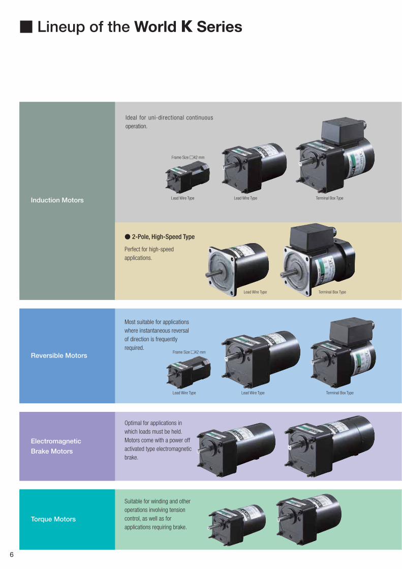
� Lineup of the World K Series
Induction Motors
Reversible Motors
Electromagnetic
Brake Motors
Torque Motors
� 2-Pole, High-Speed Type
Lead Wire Type
Ideal for uni-directional continuous operation.
Perfect for high-speed applications.
Most suitable for applications where instantaneous reversal of direction is frequently required.
Optimal for applications in which loads must be held. Motors come with a power off activated type electromagnetic brake.
Suitable for winding and other operations involving tension control, as well as for applications requiring brake.
Frame Size �42 mm
Terminal Box TypeLead Wire Type
Terminal Box TypeLead Wire Type
Lead Wire Type Terminal Box TypeLead Wire Type
Frame Size �42 mm

� For your catalogue, please contact your nearest Oriental Motor sales office.
7
Induction Motors
�42 mm �60 mm �70 mm �80 mm �90 mm Page
1 W � 3 W 6 W 15 W 25 W 40 W 60 W 90 W
Single-Phase 100 VAC✽
Lead Wire Type ● ● ● ● ● ● ●
Terminal Box Type ● ● ● ● ●
Single-Phase 110/115 VAC
Lead Wire Type ● ● ● ● ● ● ●
Terminal Box Type ● ● ● ● ●
Single-Phase 200 VAC✽
Lead Wire Type ● ● ● ● ● ● ● 8
Terminal Box Type ● ● ● ● ●
Single-Phase 220/230 VAC
Lead Wire Type ● ● ● ● ● ●
Terminal Box Type ● ● ● ● ●
Three-Phase 200/220/230 VAC
Lead Wire Type ● ● ● ● ●
Terminal Box Type ● ● ● ● ●
Three-Phase 400 VAC Terminal Box Type ● ● ● ●
2-Pole, High-Speed Type
�80 mm �90 mm Page
40 W 60 W 60 W 90 W 150 W
Single-Phase 100 VAC✽ Lead Wire Type ● ● ● ● ●
Single-Phase 110/115 VAC Lead Wire Type ● ● ● ● ●
Single-Phase 200 VAC✽ Lead Wire Type ● ● ● ● ● 37
Single-Phase 220/230 VAC Lead Wire Type ● ● ● ● ●
Three-Phase 200/220/230 VAC
Lead Wire Type ● ● ●
Terminal Box Type ●
Reversible Motors
�42 mm �60 mm �70 mm �80 mm �90 mm Page
1 W 6 W 15 W 25 W 40 W 60 W 90 W
Single-Phase 100 VAC✽
Lead Wire Type ● ● ● ● ● ● ●
Terminal Box Type ● ● ● ● ●
Single-Phase 110/115 VAC
Lead Wire Type ● ● ● ● ● ● ●
Terminal Box Type ● ● ● ● ● 42
Single-Phase 200 VAC✽
Lead Wire Type ● ● ● ● ● ● ●
Terminal Box Type ● ● ● ● ●
Single-Phase 220/230 VAC
Lead Wire Type ● ● ● ● ● ●
Terminal Box Type ● ● ● ● ●
Electromagnetic Brake Motors
�60 mm �70 mm �80 mm �90 mm Page
6 W 15 W 25 W 40 W 60 W 90 W
Single-Phase 100 VAC✽ ● ● ● ● ● ●
Single-Phase 110/115 VAC ● ● ● ● ● ● 67
Single-Phase 200 VAC✽ ● ● ● ● ● ●
Single-Phase 220/230 VAC ● ● ● ● ● ●
Three-Phase 200/220/230 VAC ● ● ● ● ●
Torque Motors
�60 mm �70 mm �80 mm �90 mm Page
3 W 6 W 10 W 20 W
Single-Phase 100 VAC✽ ● ● ● ●
Single-Phase 110/115 VAC ● ● ● ● 94
Single-Phase 200 VAC✽ ● ● ● ●
Single-Phase 220/230 VAC ● ● ● ●
Frame Size/Output Power Voltage/Type
Frame Size/Output Power Voltage/Type
Voltage/Type
Voltage
Voltage
Frame Size/Output Power
Frame Size/Output Power
Frame Size/Output Power
✽ The products for single-phase 100 VAC, single-phase 200 VAC are available. Please contact the nearest Oriental Motor sales office.

8
Induction Motors
Features
Optimal for Uni-Directional Continuous OperationInduction motors are optimal for uni-directional continuous operation such as a conveyor system.
Safety Standards and CE MarkingStandards Certification Body Standards File No. CE Marking
UL 1004UL 2111
ULE64199 (1 W�6 W Type)E64197 (15 W�150 W Type)
Low Voltage Directives
CSA C22.2 No.100CSA C22.2 No.77
EN 60950-1EN 60034-1EN 60034-5IEC 60664-1
Conform to EN/IEC Standards
GB 12350 CQC
2005010401150786 (Single-Phase 1 W, 3 W Type)2003010401091525 (Single-Phase 6 W Type)2003010401091527 (Three-Phase 6 W Type)2003010401091522 (Single-Phase 15 W�90 W Type)2003010401091520 (Three-Phase 25 W�90 W Type)2005010401150785 (2-Pole, High-Speed Type, Single-Phase 40 W�150 W Type)2005010401150788 (2-Pole, High-Speed Type, Three-Phase 60 W�150 W Type)
When the motor is approved under various safety standards, the model name on the nameplate is the approved model name.The following products are not applicable to the table above.4IK25GN-UT4, 4IK25A-UT4, 5IK40GN-UT4, 5IK40A-UT4,5IK60GE-UT4F, 5IK60A-UT4F, 5IK90GE-UT4F, 5IK90A-UT4F
Standards Certification Body Standards File No. CE Marking
EN 60950-1EN 60034-1EN 60034-5IEC 60034-11
TÜVRheinland
R50079501 Low Voltage Directives
��
�
��
RoHS-Compliant
Wo
rld K
Series
1 W / 3 W
6 W15 W
25 W40 W
60 W90 W
2-Po
le, Hig
h-S
peed
40 W�
150 W

9
System Configuration
�Example of System Configuration
AC Power Supply
Mounting Brackets (Accessories)(➜ Page 121)
Gearheads (Sold separately)
Flexible Couplings (Accessories)(➜ Page 123)
Capacitor Cap✽ (Included)Insulating cap for capacitor terminal section.
Motor
Capacitor (Included)
Brake PackSB50W (Sold separately)Equipped with instantaneous stopping functions, thermal protector open detection functions.(➜ Page 114)
: Required under this system.: Selectable according to necessity. Oriental Motor provides.
Motor(Pinion Shaft)
4IK25GN-CW2E
(Body) (Sold separately)
Mounting BracketLong Life/Low NoiseGN-S Gearhead
4GN25S SOL4M5 MCL301012
Flexible Coupling
Right-Angle Gearheads (Sold separately)(➜ Page 108)
✽Capacitor cap is included.
The system configuration shown above is an example. Other configurations are available.
Product Number Code
Motor
5 I K 40 GN - CW 2 T Eq w e r yt i ou
� Motor Frame Size 0: 42 mm 2: 60 mm 3: 70 mm 4: 80 mm 5: 90 mm
� Motor Type I: Induction Motor
� Series K: K Series
� Output Power (W) (Example) 40: 40 W
� Motor Shaft Type GN: GN Type Pinion Shaft GE: GE Type Pinion Shaft A: Round Shaft
�Power Supply Voltage/Number of Poles
AW: Single-Phase 100 VAC, 110/115 VAC 4-Pole BW: Single-Phase 100 VAC, 110/115 VAC 2-Pole CW: Single-Phase 200 VAC, 220/230 VAC 4-PoleDW: Single-Phase 200 VAC, 220/230 VAC 2-Pole SW: Three-Phase 200/220/230 VAC 4-Pole TW: Three-Phase 200/220/230 VAC 2-Pole U: Three-Phase 400 VAC 4-Pole
2, 3: RoHS-Compliant
T, T4, T4F: Terminal Box Type
� Included Capacitor J: For Single-Phase 100 VAC, 200 VAC U: For Single-Phase 110/115 VAC E: For Single-Phase 220/230 VAC Blank: Three-Phase Type
The J, U and E at the end of the model name indicate that the unit includes a capacitor. These letters are not listed on the motor nameplate. When the motor is approved under various safety standards, the model name on the nameplate is the approved model name.(Example) Model: 5IK40GN-CW2E ➜ Motor nameplate and product approved under various safety standards: 5IK40GN-CW2
Gearhead
5 GN 50 Sq w e r
� Gearhead Frame Size 0: 42 mm 2: 60 mm 3: 70 mm 4: 80 mm 5: 90 mm
� Type of Pinion GN: GN Type Pinion GE: GE Type Pinion
� Gear Ratio (Example) 50: Gear Ratio of 1:50 10X denotes the decimal gearhead of gear ratio 1:10
�
GN Type PinionS: Long Life/Low Noise GN-S Gearhead, RoHS-Compliant K: GN-K GearheadRH: Right-Angle/Hollow Shaft Gearhead, RoHS-Compliant RA: Right-Angle/Solid Shaft Gearhead, RoHS-Compliant
GE Type PinionS: Long Life GE-S GearheadRH: Right-Angle/Hollow Shaft Gearhead, RoHS-Compliant RA: Right-Angle/Solid Shaft Gearhead, RoHS-Compliant
GN-K gearhead of frame size 42 mm complies to RoHS directive.
�
�
��
�
�
✽
Wo
rld K
Series
Ind
uctio
n M
oto
rsR
eversible M
oto
rsE
lec
trom
ag
ne
tic B
rak
e
Mo
tors
Torq
ue M
oto
rsR
igh
t-An
gle
Gearh
eads
Bra
ke
Pa
ck
SB5
0W
Accesso
ries2
-Po
le,
Hig
h-S
peed
Typ
e

10
General Specifications of Motors
1 W, 3 W TypeItem Specifications
Insulation Resistance100 M� or more when 500 VDC megger is applied between the windings and the frame after rated motor operation under normal ambient temperature and humidity.
Dielectric StrengthSufficient to withstand 1.5 kV at 50 Hz or 60 Hz applied between the windings and the frame for 1 minute after rated motor operation under normal ambient temperature and humidity.
Temperature RiseTemperature rise of windings are 75˚C or less measured by the resistance change method after rated motor operation under normal ambient temperature and humidity, with connecting a gearhead or equivalent heat radiation plate✽1.
Insulation Class UL/CSA standards: Class A (105˚C), EN standards: Class E (120˚C)Overheat Protection Impedance protectedAmbient Temperature �10˚C��40˚C (nonfreezing)Ambient Humidity 85% or less (noncondensing)Degree of Protection IP20
6 W�90 W Type, 2-Pole, High-Speed TypeItem Specifications
Insulation Resistance100 M� or more when 500 VDC megger is applied between the windings and the frame after rated motor operation under normal ambient temperature and humidity.
Dielectric StrengthSufficient to withstand 1.5 kV (three-phase 400 VAC: 2 kV) at 50 Hz and 60 Hz applied between the windings and the frame for 1 minute after rated motor operation under normal ambient temperature and humidity.
Temperature RiseTemperature rise of windings are 80˚C or less measured by the resistance change method under normal ambient temperature and humidity, after rated motor operation with connecting a gearhead or equivalent heat radiation plate✽1. (Three-phase type: 70˚C or less)
Insulation Class✽2 Class B (130˚C)
Overheat Protection6 W type has impedance protection.All others have built-in thermal protector (automatic return type) Operating temperature; open: 130˚C�5˚C, close: 82˚C�15˚C
Ambient TemperatureSingle-phase 100 VAC, Single-phase 200 VAC, Three-phase 200 VAC: �10˚C��50˚C (nonfreezing)Other voltage: �10˚C��40˚C (nonfreezing)
Ambient Humidity 85% or less (noncondensing)
Degree of Protection
Lead Wire Type: IP20Terminal Box Type: 6 W Type IP65 (excluding the installation surface of the round shaft type) 25 W, 40 W, 60 W, 90 W Type (Pinion Shaft Type) IP54 25 W, 40 W, 60 W, 90 W Type (Round Shaft Type) IP40
1 Heat radiation plate (Material: Aluminum)
Motor Type Size (mm) Thickness (mm)1 W, 3 W Type 80�80
5
6 W Type 115�11515 W Type 125�12525 W Type (2-Pole, High-Speed 4IK40 Type, 4IK60 Type) 135�13540 W Type (2-Pole, High-Speed 5IK60 Type) 165�16560 W, 90 W, 150 W Type 200�200
2 The following products are recognized as class E (120˚C).4IK25GN-UT4, 4IK25A-UT4, 5IK40GN-UT4, 5IK40A-UT4,5IK60GE-UT4F, 5IK60A-UT4F, 5IK90GE-UT4F, 5IK90A-UT4F
��
�
✽
✽
Wo
rld K
Series
1 W / 3 W
6 W15 W
25 W40 W
60 W90 W
2-Po
le, Hig
h-S
peed
40 W�
150 W

11
Induction Motors
1 W / 3 WFrame Size: �42 mm
(Gearhead sold separately)
Specifications – Continuous Rating Model
Lead Wire TypeOutputPower
Voltage Frequency Current Starting Torque Rated TorqueRatedSpeed
Capacitor
Pinion Shaft Type Round Shaft Type W VAC Hz A mN�m mN�m r/min �F
0IK1GN-AW2J 0IK1A-AW2J 1 Single-Phase 10050 0.107
89.5 1000
1.560 0.102 8 1200
0IK1GN-AW3U 0IK1A-AW3U 1Single-Phase 110
600.074
8 8 1200 1.0Single-Phase 115 0.078
0IK1GN-CW2J 0IK1A-CW2J0.8
Single-Phase 20050 0.057
7 81000
0.351 60 0.055 1200
0IK3GN-BW2J 0IK3A-BW2J 3 Single-Phase 10050 0.109
612 2400
1.860 0.123 10 3000
0IK3GN-BW3U 0IK3A-BW3U 3Single-Phase 110
600.115
6 10 3000 1.5Single-Phase 115 0.118
0IK3GN-DW2J 0IK3A-DW2J2.5
Single-Phase 20050 0.057
5 9.52500
0.453 60 0.064 3100
The J and U at the end of the model name indicate that the unit includes a capacitor. These letters are not listed on the motor nameplate.When the motor is approved under various safety standards, the model name on the nameplate is the approved model name.
: Impedance protected
�
�
Product Line
Motor
TypeModel
Pinion Shaft Type Round Shaft Type
Lead Wire
0IK1GN-AW2J 0IK1A-AW2J0IK1GN-AW3U 0IK1A-AW3U0IK1GN-CW2J 0IK1A-CW2J0IK3GN-BW2J 0IK3A-BW2J0IK3GN-BW3U 0IK3A-BW3U0IK3GN-DW2J 0IK3A-DW2J
�� Gearhead (Sold Separately)
Type Gearhead Model Gear Ratio
Parallel Shaft 0GN�K3, 3.6, 5, 6, 7.5, 9, 12.5, 15, 18, 25, 30, 36, 50, 60, 75,
90, 100, 120, 150, 180
Enter the gear ratio in the box (�) within the model name.
�
�
Wo
rld K
Series
Ind
uctio
n M
oto
rsR
eversible M
oto
rsE
lec
trom
ag
ne
tic B
rak
e
Mo
tors
Torq
ue M
oto
rsR
igh
t-An
gle
Gearh
eads
Bra
ke
Pa
ck
SB5
0W
Accesso
ries2
-Po
le,
Hig
h-S
peed
Typ
e

12
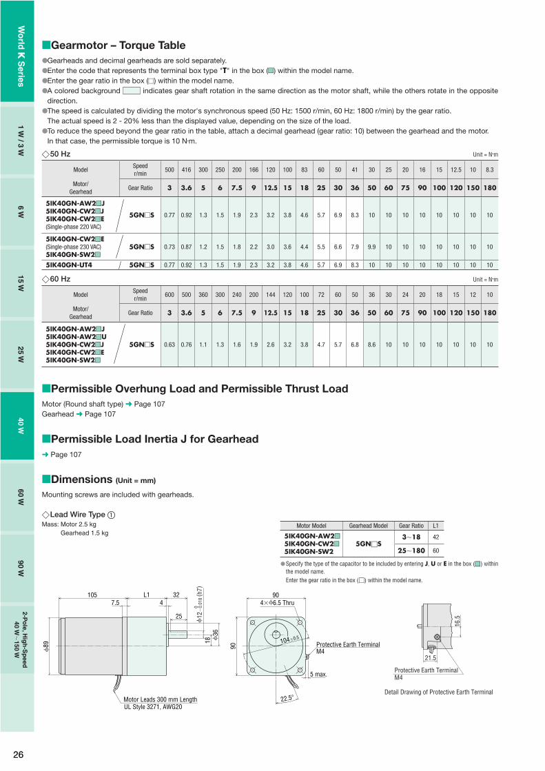
Gearmotor – Torque TableGearheads are sold separately. Decimal gearheads are not available.Enter the gear ratio in the box (�) within the model name.A colored background indicates gear shaft rotation in the same direction as the motor shaft, while the others rotate in the opposite direction.The speed is calculated by dividing the motor's synchronous speed (4-pole type; 50 Hz: 1500 r/min, 60 Hz: 1800 r/min, 2-pole type; 50 Hz: 3000 r/min, 60 Hz: 3600 r/min) by the gear ratio. The actual speed is 2 - 33% less than the displayed value, depending on the size of the load.50 Hz Unit = N�m
ModelSpeedr/min
500 416 300 250 200 166 120 100 83 60 50 41 30 25 20 16 15 12.5 10 8.3
Motor/Gearhead
Gear Ratio 3 3.6 5 6 7.5 9 12.5 15 18 25 30 36 50 60 75 90 100 120 150 180
0IK1GN-AW2J 0GN�K 0.023 0.028 0.038 0.046 0.058 0.069 0.087 0.1 0.12 0.16 0.19 0.23 0.31 0.38 0.42 0.5 0.56 0.67 0.84 1
0IK1GN-CW2J 0GN�K 0.019 0.023 0.032 0.039 0.049 0.058 0.073 0.088 0.11 0.13 0.16 0.19 0.26 0.32 0.35 0.42 0.47 0.57 0.71 0.85
Unit = N�m
ModelSpeedr/min
1000 833 600 500 400 333 240 200 166 120 100 83 60 50 40 33 30 25 20 16
Motor/Gearhead
Gear Ratio 3 3.6 5 6 7.5 9 12.5 15 18 25 30 36 50 60 75 90 100 120 150 180
0IK3GN-BW2J 0GN�K 0.029 0.035 0.049 0.058 0.073 0.087 0.11 0.13 0.16 0.2 0.24 0.29 0.4 0.48 0.53 0.64 0.71 0.85 1 1
0IK3GN-DW2J 0GN�K 0.023 0.028 0.038 0.046 0.058 0.069 0.087 0.1 0.12 0.16 0.19 0.23 0.31 0.38 0.42 0.5 0.56 0.67 0.84 1
60 Hz Unit = N�m
ModelSpeedr/min
600 500 360 300 240 200 144 120 100 72 60 50 36 30 24 20 18 15 12 10
Motor/Gearhead
Gear Ratio 3 3.6 5 6 7.5 9 12.5 15 18 25 30 36 50 60 75 90 100 120 150 180
0IK1GN-AW2J0IK1GN-AW3U0IK1GN-CW2J
0GN�K 0.019 0.023 0.032 0.039 0.049 0.058 0.073 0.088 0.11 0.13 0.16 0.19 0.26 0.32 0.35 0.42 0.47 0.57 0.71 0.85
Unit = N�m
ModelSpeedr/min
1200 1000 720 600 480 400 288 240 200 144 120 100 72 60 48 40 36 30 24 20
Motor/Gearhead
Gear Ratio 3 3.6 5 6 7.5 9 12.5 15 18 25 30 36 50 60 75 90 100 120 150 180
0IK3GN-BW2J0IK3GN-BW3U 0GN�K 0.024 0.029 0.041 0.049 0.061 0.073 0.091 0.11 0.13 0.17 0.2 0.24 0.33 0.4 0.44 0.53 0.59 0.71 0.89 1
0IK3GN-DW2J 0GN�K 0.023 0.028 0.038 0.046 0.058 0.069 0.087 0.1 0.12 0.16 0.19 0.23 0.31 0.38 0.42 0.5 0.56 0.67 0.84 1
Permissible Overhung Load and Permissible Thrust LoadMotor (Round shaft type) ➜ Page 107Gearhead ➜ Page 107
Permissible Load Inertia J for Gearhead➜ Page 107
Dimensions (Unit = mm)
Mounting screws are included with gearheads.
����
�
�
�
�
�
�
Lead Wire TypeMass: Motor 0.3 kg Gearhead 0.2 kg
48�0.542
10
8 18
263
4.512
5
Motor Leads 300 mm LengthUL Style 3266, AWG2216.5
28
7.5
2
0
5�0.
012
( h7)
2060
42
4�3.5 Thru
Protective Earth TerminalM4
7 m
ax.
� Shaft Section of Round Shaft TypeThe mass and motor's dimensions (excluding the shaft section) are the same as those of the pinion shaft type.
201.5
48�0.5
4�3.5 Thru
5�
0.01
2 (h7
)0
42
42
10
0
37.6
�0.
025 (
h7)
Protective Earth TerminalM4
7 m
ax.
�
10
7.25
Detail Drawing of Protective Earth Terminal
Protective Earth Terminal M4
Wo
rld K
Series
1 W / 3 W
6 W15 W
25 W40 W
60 W90 W
2-Po
le, Hig
h-S
peed
40 W�
150 W

13
Capacitor (Included with the motors)
4.3 20
A
CB�
10B4.
54
10 6AMP#187
� Capacitor Dimensions (mm)Model Capacitor
ModelA B C
Mass(g)
CapacitorCapPinion Shaft Type Round Shaft Type
0IK1GN-AW2J 0IK1A-AW2J CH15FAUL 31 14.5 23.5 18
Included
0IK1GN-AW3U 0IK1A-AW3U CH10FAUL 31 14.5 23.5 18
0IK1GN-CW2J 0IK1A-CW2J CH035BFAUL 31 17 27 24
0IK3GN-BW2J 0IK3A-BW2J CH18FAUL 31 14.5 23.5 18
0IK3GN-BW3U 0IK3A-BW3U CH15FAUL 31 14.5 23.5 18
0IK3GN-DW2J 0IK3A-DW2J CH045BFAUL 31 17 27 24
�
Connection DiagramsThe direction of motor rotation is as viewed from the shaft end of the motor. CW represents the clockwise direction, while CCW represents the counterclockwise direction.Connection diagrams are also valid for the equivalent round shaft type.
Clockwise Counterclockwise
0IK1GN-AW2J, 0IK1GN-AW3U, 0IK1GN-CW2J0IK3GN-BW2J, 0IK3GN-BW3U, 0IK3GN-DW2J
Capacitor
Black
RedL
N
White
MotorPE
CW
White
RedL
NBlack
MotorPE
Capacitor
CCW
PE: Protective EarthNote:Change the direction of single-phase motor rotation only after bringing the motor to a stop. If an attempt is made to change the direction of rotation while the motor is rotating, motor may ignore reversing command or change its direction of rotation after some delay.
��
�
Wo
rld K
Series
Ind
uctio
n M
oto
rsR
eversible M
oto
rsE
lec
trom
ag
ne
tic B
rak
e
Mo
tors
Torq
ue M
oto
rsR
igh
t-An
gle
Gearh
eads
Bra
ke
Pa
ck
SB5
0W
Accesso
ries2
-Po
le,
Hig
h-S
peed
Typ
e
14
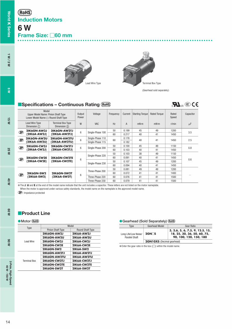
Product Line
Motor
TypeModel
Pinion Shaft Type Round Shaft Type
Lead Wire
2IK6GN-AW2J 2IK6A-AW2J2IK6GN-AW2U 2IK6A-AW2U2IK6GN-CW2J 2IK6A-CW2J2IK6GN-CW2E 2IK6A-CW2E2IK6GN-SW2 2IK6A-SW2
Terminal Box
2IK6GN-AW2TJ 2IK6A-AW2TJ2IK6GN-AW2TU 2IK6A-AW2TU2IK6GN-CW2TJ 2IK6A-CW2TJ2IK6GN-CW2TE 2IK6A-CW2TE2IK6GN-SW2T 2IK6A-SW2T
�� Gearhead (Sold Separately)
Type Gearhead Model Gear Ratio
Long Life/Low Noise/ Parallel Shaft
2GN�S3, 3.6, 5, 6, 7.5, 9, 12.5, 15, 18, 25, 30, 36, 50, 60, 75,
90, 100, 120, 150, 1802GN10XS (Decimal gearhead)
Enter the gear ratio in the box (�) within the model name.
�
�
Induction Motors
6 WFrame Size: �60 mm
Specifications – Continuous Rating Model
Upper Model Name: Pinion Shaft TypeLower Model Name ( ): Round Shaft Type
OutputPower
W
Voltage
VAC
Frequency
Hz
Current
A
Starting Torque
mN�m
Rated Torque
mN�m
RatedSpeed
r/min
Capacitor
�FLead Wire TypeDimension �
Terminal Box TypeDimension �
2IK6GN-AW2J(2IK6A-AW2J)
2IK6GN-AW2TJ(2IK6A-AW2TJ) 6 Single-Phase 100
50 0.199 45 49 12003.5
60 0.217 40 41 1450
2IK6GN-AW2U(2IK6A-AW2U)
2IK6GN-AW2TU(2IK6A-AW2TU) 6
Single-Phase 11060
0.17840 41 1450 2.5
Single-Phase 115 0.182
2IK6GN-CW2J(2IK6A-CW2J)
2IK6GN-CW2TJ(2IK6A-CW2TJ) 6 Single-Phase 200
50 0.100 45 49 11500.8
60 0.103 40 41 1450
2IK6GN-CW2E(2IK6A-CW2E)
2IK6GN-CW2TE(2IK6A-CW2TE) 6
Single-Phase 22050 0.103 38 49 1150
0.660 0.091 40 41 1450
Single-Phase 23050 0.107 45 49 120060 0.094 40 41 1450
2IK6GN-SW2(2IK6A-SW2)
2IK6GN-SW2T(2IK6A-SW2T) 6
Three-Phase 20050 0.081 49 49 1200
�60 0.072 41 41 1400
Three-Phase 220 60 0.076 41 41 1500Three-Phase 230 60 0.079 41 41 1500
The J, U and E at the end of the model name indicate that the unit includes a capacitor. These letters are not listed on the motor nameplate.When the motor is approved under various safety standards, the model name on the nameplate is the approved model name.
: Impedance protected
�
�
Lead Wire Type Terminal Box Type
(Gearhead sold separately)
Wo
rld K
Series
1 W / 3 W
6 W15 W
25 W40 W
60 W90 W
2-Po
le, Hig
h-S
peed
40 W�
150 W
15
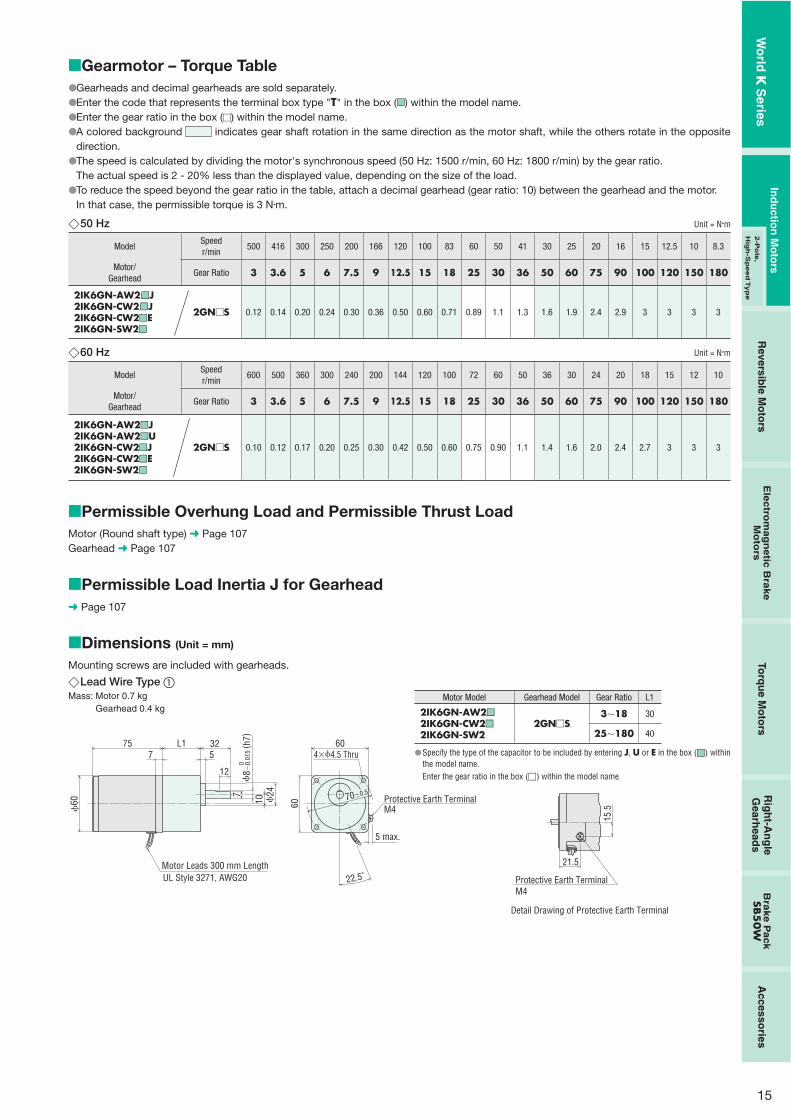
Gearmotor – Torque TableGearheads and decimal gearheads are sold separately.Enter the code that represents the terminal box type "T" in the box (��) within the model name.Enter the gear ratio in the box (�) within the model name.A colored background indicates gear shaft rotation in the same direction as the motor shaft, while the others rotate in the opposite direction.The speed is calculated by dividing the motor's synchronous speed (50 Hz: 1500 r/min, 60 Hz: 1800 r/min) by the gear ratio.The actual speed is 2 - 20% less than the displayed value, depending on the size of the load.To reduce the speed beyond the gear ratio in the table, attach a decimal gearhead (gear ratio: 10) between the gearhead and the motor.In that case, the permissible torque is 3 N�m.
50 Hz Unit = N�m
ModelSpeedr/min
500 416 300 250 200 166 120 100 83 60 50 41 30 25 20 16 15 12.5 10 8.3
Motor/Gearhead
Gear Ratio 3 3.6 5 6 7.5 9 12.5 15 18 25 30 36 50 60 75 90 100 120 150 180
2IK6GN-AW2m��J2IK6GN-CW2m��J2IK6GN-CW2��E2IK6GN-SW2��
2GN�S 0.12 0.14 0.20 0.24 0.30 0.36 0.50 0.60 0.71 0.89 1.1 1.3 1.6 1.9 2.4 2.9 3 3 3 3
60 Hz Unit = N�m
ModelSpeedr/min
600 500 360 300 240 200 144 120 100 72 60 50 36 30 24 20 18 15 12 10
Motor/Gearhead
Gear Ratio 3 3.6 5 6 7.5 9 12.5 15 18 25 30 36 50 60 75 90 100 120 150 180
2IK6GN-AW2��J2IK6GN-AW2��U2IK6GN-CW2��J2IK6GN-CW2��E2IK6GN-SW2��
2GN�S 0.10 0.12 0.17 0.20 0.25 0.30 0.42 0.50 0.60 0.75 0.90 1.1 1.4 1.6 2.0 2.4 2.7 3 3 3
Permissible Overhung Load and Permissible Thrust LoadMotor (Round shaft type) ➜ Page 107Gearhead ➜ Page 107
Permissible Load Inertia J for Gearhead➜ Page 107
Dimensions (Unit = mm)
Mounting screws are included with gearheads.
�����
�
�
�
�
�
�
�
Lead Wire Type �Mass: Motor 0.7 kg Gearhead 0.4 kg
4�4.5 Thru
Motor Leads 300 mm LengthUL Style 3271, AWG20
75 L1 325
10
12
24
60
60
7
7 70�0.5
22.5˚
60
8 �
0.01
5( h
7)0
Protective Earth TerminalM4
5 max.
�Motor Model Gearhead Model Gear Ratio L1
2IK6GN-AW2��
2IK6GN-CW2��
2IK6GN-SW22GN�S
3�18 30
25�180 40
Specify the type of the capacitor to be included by entering J, U or E in the box (��) within the model name.Enter the gear ratio in the box (�) within the model name.
15.5
21.5
Detail Drawing of Protective Earth Terminal
Protective Earth TerminalM4
�
Wo
rld K
Series
Ind
uctio
n M
oto
rsR
eversible M
oto
rsE
lec
trom
ag
ne
tic B
rak
e
Mo
tors
Torq
ue M
oto
rsR
igh
t-An
gle
Gearh
eads
Bra
ke
Pa
ck
SB5
0W
Accesso
ries2
-Po
le,
Hig
h-S
peed
Typ
e

16
Capacitor(Included with single-phase motors)
4.3 20
A
CB�
10B4.
54
10 6AMP#187
� Capacitor Dimensions (mm)
ModelUpper Model Name: Pinion Shaft Type
Lower Model Name ( ): Round Shaft TypeCapacitor
ModelA B C
Mass(g)
CapacitorCap
Lead Wire Type Terminal Box Type
2IK6GN-AW2J(2IK6A-AW2J)
2IK6GN-AW2TJ(2IK6A-AW2TJ) CH35FAUL2 31 17 27 25
Included
2IK6GN-AW2U(2IK6A-AW2U)
2IK6GN-AW2TU(2IK6A-AW2TU) CH25FAUL2 31 17 27 25
2IK6GN-CW2J(2IK6A-CW2J)
2IK6GN-CW2TJ(2IK6A-CW2TJ) CH08BFAUL 31 17 27 20
2IK6GN-CW2E(2IK6A-CW2E)
2IK6GN-CW2TE(2IK6A-CW2TE) CH06BFAUL 31 14.5 23.5 15
�
Terminal Box Type �Mass: Motor 0.9 kg Gearhead 0.4 kg
62
46.5
91.5
1157
32 m
ax.
L15 12
24
32
10
7
4�4.5 Thru
70�0.5
8�
0.01
5( h
7)0
60
60
Use cable with a diameter of 8 � 12 mm.
�
�
Motor Model Gearhead Model Gear Ratio L1
2IK6GN-AW2T��
2IK6GN-CW2T��
2IK6GN-SW2T2GN�S
3�18 30
25�180 40
Specify the type of the capacitor to be included by entering J, U or E in the box (��) within the model name.Enter the gear ratio in the box (�) within the model name.
�
Shaft Section of Round Shaft TypeThe mass and motor's dimensions (excluding the shaft section)are the same as those of the pinion shaft type.
224
22.5˚
4�4.5 Thru
70�0.5
�60
54
�0.
030
( h7)
0
6 �
0.01
2( h
7)0
Protective Earth Terminal M4(Lead Wire Type Only)
5 max.
� Decimal GearheadCan be connected to GN pinion shaft type.2GN10XSMass: 0.2 kg
38.526 12.5
2 4�4.5 Thru
70�0.5
�60
54
�0.
030
( h7)
0
�
Wo
rld K
Series
1 W / 3 W
6 W15 W
25 W40 W
60 W90 W
2-Po
le, Hig
h-S
peed
40 W�
150 W

17
Connection DiagramsThe direction of motor rotation is as viewed from the shaft end of the motor. CW represents the clockwise direction, while CCW represents the counterclockwise direction.Connection diagrams are also valid for the equivalent round shaft type.Specify the type of the capacitor to be included by entering J, U or E in the box (�) within the model name.
Lead Wire Type Terminal Box Type
2IK6GN-AW2�
2IK6GN-CW2�
2IK6GN-AW2T�
2IK6GN-CW2T�2IK6GN-SW2T
Counterclockwise
Counterclockwise
Counterclockwise
ClockwiseClockwise ClockwiseClockwise
Counterclockwise
2IK6GN-SW2
CW
U1U2Z2
Capacitor
LN
Motor
PE
U1U2Z2
L
NMotor
Capacitor
CCW
PE
U1U2Z2
Red
White
BlackMotor
PE
CW
L1(R)
L2(S)
L3(T)
UVW
L1(R)L2(S)L3(T)
Motor
CW
PECapacitor
Black
RedL
N
White
MotorPE
CW
White
RedL
NBlack
MotorPE
Capacitor
CCW
To change the rotation direction, change any two connections between R, S and T.
To change the rotation direction, change any two connections between U, V and W.
PE: Protective EarthNote:Change the direction of single-phase motor rotation only after bringing the motor to a stop.If an attempt is made to change the direction of rotation while the motor is rotating, motor may ignore reversing command or change its direction of rotation after some delay.
��
��
Wo
rld K
Series
Ind
uctio
n M
oto
rsR
eversible M
oto
rsE
lec
trom
ag
ne
tic B
rak
e
Mo
tors
Torq
ue M
oto
rsR
igh
t-An
gle
Gearh
eads
Bra
ke
Pa
ck
SB5
0W
Accesso
ries2
-Po
le,
Hig
h-S
peed
Typ
e

18
Induction Motors
15 WFrame Size: �70 mm
Specifications – Continuous Rating Model
Lead Wire TypeOutputPower
Voltage Frequency Current Starting Torque Rated TorqueRatedSpeed
Capacitor
Pinion Shaft Type Round Shaft Type W VAC Hz A mN�m mN�m r/min �F
3IK15GN-AW2J 3IK15A-AW2J 15 Single-Phase 10050 0.36 80 125 1200
5.560 0.37 65 105 1450
3IK15GN-AW2U 3IK15A-AW2U 15Single-Phase 110
600.33
65 105 1450 4.5Single-Phase 115 0.34
3IK15GN-CW2J 3IK15A-CW2J 15 Single-Phase 20050 0.18 80 125 1200
1.560 0.19 65 105 1450
3IK15GN-CW2E 3IK15A-CW2E 15Single-Phase 220
50 0.19 70 125 1200
1.060 0.16 65 105 1450
Single-Phase 23050 0.19 75 125 120060 0.16 65 105 1450
The J, U and E at the end of the model name indicate that the unit includes a capacitor. These letters are not listed on the motor nameplate.When the motor is approved under various safety standards, the model name on the nameplate is the approved model name.
: Contains a built-in thermal protector. If a motor overheats for any reason, the thermal protector is opened and the motor stops.When the motor temperature drops, the thermal protector closes and the motor restarts. Be sure to turn the motor off before inspecting.
�
�
Product Line
Motor
TypeModel
Pinion Shaft Type Round Shaft Type
Lead Wire
3IK15GN-AW2J 3IK15A-AW2J3IK15GN-AW2U 3IK15A-AW2U3IK15GN-CW2J 3IK15A-CW2J3IK15GN-CW2E 3IK15A-CW2E
�� Gearhead (Sold Separately)
Type Gearhead Model Gear Ratio
Long Life/Low Noise/ Parallel Shaft
3GN�S3, 3.6, 5, 6, 7.5, 9, 12.5, 15, 18, 25, 30, 36, 50, 60, 75,
90, 100, 120, 150, 1803GN10XS (Decimal gearhead)
Enter the gear ratio in the box (�) within the model name.
�
�
(Gearhead sold separately)
Wo
rld K
Series
1 W / 3 W
6 W15 W
25 W40 W
60 W90 W
2-Po
le, Hig
h-S
peed
40 W�
150 W
19
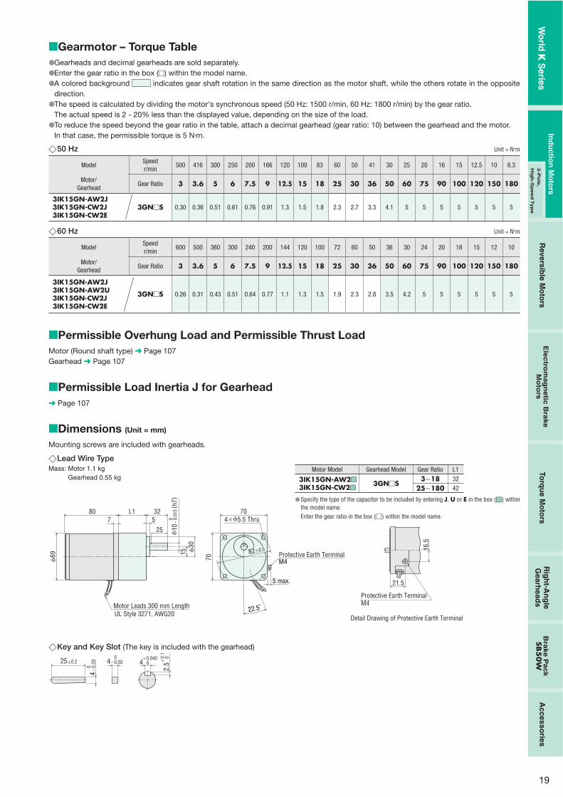
Lead Wire TypeMass: Motor 1.1 kg Gearhead 0.55 kg
69
807
L1 325
25
15 30
82�0.5
Motor Leads 300 mm LengthUL Style 3271, AWG20
70
70
4�5.5 Thru
22.5˚
10
�0.
015
( h7)
0
Protective Earth TerminalM4
5 max.
�Motor Model Gearhead Model Gear Ratio L1
3IK15GN-AW2��
3IK15GN-CW2��3GN�S
3�18 32
25�180 42
Specify the type of the capacitor to be included by entering J, U or E in the box (��) within the model name.Enter the gear ratio in the box (�) within the model name.
16.5
21.5
Detail Drawing of Protective Earth Terminal
Protective Earth TerminalM4
�
Gearmotor – Torque TableGearheads and decimal gearheads are sold separately.Enter the gear ratio in the box (�) within the model name.A colored background indicates gear shaft rotation in the same direction as the motor shaft, while the others rotate in the opposite direction.The speed is calculated by dividing the motor's synchronous speed (50 Hz: 1500 r/min, 60 Hz: 1800 r/min) by the gear ratio.The actual speed is 2 - 20% less than the displayed value, depending on the size of the load.To reduce the speed beyond the gear ratio in the table, attach a decimal gearhead (gear ratio: 10) between the gearhead and the motor.In that case, the permissible torque is 5 N�m.
50 Hz Unit = N�m
ModelSpeedr/min
500 416 300 250 200 166 120 100 83 60 50 41 30 25 20 16 15 12.5 10 8.3
Motor/Gearhead
Gear Ratio 3 3.6 5 6 7.5 9 12.5 15 18 25 30 36 50 60 75 90 100 120 150 180
3IK15GN-AW2J3IK15GN-CW2J3IK15GN-CW2E
3GN�S 0.30 0.36 0.51 0.61 0.76 0.91 1.3 1.5 1.8 2.3 2.7 3.3 4.1 5 5 5 5 5 5 5
60 Hz Unit = N�m
ModelSpeedr/min
600 500 360 300 240 200 144 120 100 72 60 50 36 30 24 20 18 15 12 10
Motor/Gearhead
Gear Ratio 3 3.6 5 6 7.5 9 12.5 15 18 25 30 36 50 60 75 90 100 120 150 180
3IK15GN-AW2J3IK15GN-AW2U3IK15GN-CW2J3IK15GN-CW2E
3GN�S 0.26 0.31 0.43 0.51 0.64 0.77 1.1 1.3 1.5 1.9 2.3 2.8 3.5 4.2 5 5 5 5 5 5
Permissible Overhung Load and Permissible Thrust LoadMotor (Round shaft type) ➜ Page 107Gearhead ➜ Page 107
Permissible Load Inertia J for Gearhead➜ Page 107
Dimensions (Unit = mm)
Mounting screws are included with gearheads.
����
�
�
�
�
�
�
�
Key and Key Slot (The key is included with the gearhead)
25�0.2 4 0�0.040
2.5
0�0.
1
4�0.
03 0
4�0.03 0
�
Wo
rld K
Series
Ind
uctio
n M
oto
rsR
eversible M
oto
rsE
lec
trom
ag
ne
tic B
rak
e
Mo
tors
Torq
ue M
oto
rsR
igh
t-An
gle
Gearh
eads
Bra
ke
Pa
ck
SB5
0W
Accesso
ries2
-Po
le,
Hig
h-S
peed
Typ
e

20
Shaft Section of Round Shaft TypeThe mass and motor's dimensions (excluding the shaft section) are the same as those of the pinion shaft type.
4�5.5 Thru232
82�0.5
�70
22.5˚
64
�0.
030
( h7)
0
6 �0.
012
( h7)
0
5 max.
Protective Earth TerminalM4
� Decimal GearheadCan be connected to GN pinion shaft type.3GN10XSMass: 0.3 kg
4330 13
2 4�5.5 Thru
82�0.5
64
�0.
030
( h7)
0 �70
�
Capacitor Dimensions (mm)Model Capacitor
ModelA B C
Mass(g)
CapacitorCapPinion Shaft Type Round Shaft Type
3IK15GN-AW2J 3IK15A-AW2J CH55FAUL2 38 21 31 40
Included3IK15GN-AW2U 3IK15A-AW2U CH45FAUL2 37 18 27 303IK15GN-CW2J 3IK15A-CW2J CH15BFAUL 38 21 31 353IK15GN-CW2E 3IK15A-CW2E CH10BFAUL 37 18 27 30
�Capacitor(Included with single-phase motors)
4.3 20
A
CB�
10B4.
54
10 6AMP#187
�
Connection DiagramsThe direction of motor rotation is as viewed from the shaft end of the motor. CW represents the clockwise direction, while CCW represents the counterclockwise direction.Connection diagrams are also valid for the equivalent round shaft type.Specify the type of the capacitor to be included by entering J, U or E in the box (�) within the model name.
3IK15GN-AW2�
3IK15GN-CW2�
Clockwise Counterclockwise
Capacitor
Black
RedL
N
White
Black
Red
White
MotorPE
CW
L
N
MotorPE
Capacitor
CCW
PE: Protective EarthNote:Change the direction of single-phase motor rotation only after bringing the motor to a stop.If an attempt is made to change the direction of rotation while the motor is rotating, motor may ignore reversing command or change its direction of rotation after some delay.
��
��
Wo
rld K
Series
1 W / 3 W
6 W15 W
25 W40 W
60 W90 W
2-Po
le, Hig
h-S
peed
40 W�
150 W

21
Product Line
Motor
TypeModel
Pinion Shaft Type Round Shaft Type
Lead Wire
4IK25GN-AW2J 4IK25A-AW2J4IK25GN-AW2U 4IK25A-AW2U4IK25GN-CW2J 4IK25A-CW2J4IK25GN-CW2E 4IK25A-CW2E4IK25GN-SW2 4IK25A-SW2
Terminal Box
4IK25GN-AW2TJ 4IK25A-AW2TJ4IK25GN-AW2TU 4IK25A-AW2TU4IK25GN-CW2TJ 4IK25A-CW2TJ4IK25GN-CW2TE 4IK25A-CW2TE4IK25GN-SW2T 4IK25A-SW2T4IK25GN-UT4 4IK25A-UT4
�� Gearhead/Right-Angle Gearhead (Sold Separately)
Type Gearhead Model Gear Ratio
Long Life/Low Noise/ Parallel Shaft
4GN�S3, 3.6, 5, 6, 7.5, 9, 12.5, 15, 18, 25, 30, 36, 50, 60, 75,
90, 100, 120, 150, 1804GN10XS (Decimal gearhead)
Right-Angle/Hollow Shaft
4GN�RH3, 3.6, 5, 6, 7.5, 9, 12.5, 15, 18, 25, 30, 36, 50, 60, 75,
90, 100, 120, 150, 180
Right-Angle/Solid Shaft
4GN�RA3, 3.6, 5, 6, 7.5, 9, 12.5, 15, 18, 25, 30, 36, 50, 60, 75,
90, 100, 120, 150, 180
Enter the gear ratio in the box (�) within the model name.
�
�
Induction Motors
25 WFrame Size: �80 mm
Specifications – Continuous Rating Model
Upper Model Name: Pinion Shaft TypeLower Model Name ( ): Round Shaft Type
OutputPower
W
Voltage
VAC
Frequency
Hz
Current
A
Starting Torque
mN�m
Rated Torque
mN�m
RatedSpeed
r/min
Capacitor
�FLead Wire TypeDimension �
Terminal Box TypeDimension �
4IK25GN-AW2J(4IK25A-AW2J)
4IK25GN-AW2TJ(4IK25A-AW2TJ) 25 Single-Phase 100
50 0.51 130 205 12008.0
60 0.52 120 170 1450
4IK25GN-AW2U(4IK25A-AW2U)
4IK25GN-AW2TU(4IK25A-AW2TU) 25
Single-Phase 11060 0.46 120 170 1450 6.5
Single-Phase 115
4IK25GN-CW2J(4IK25A-CW2J)
4IK25GN-CW2TJ(4IK25A-CW2TJ) 25 Single-Phase 200
500.26 120
205 12002.0
60 170 1450
4IK25GN-CW2E(4IK25A-CW2E)
4IK25GN-CW2TE(4IK25A-CW2TE) 25
Single-Phase 22050 0.27
110205 1200
1.560 0.23 170 1450
Single-Phase 23050 0.27
120205 1200
60 0.23 170 1450
4IK25GN-SW2(4IK25A-SW2)
4IK25GN-SW2T(4IK25A-SW2T) 25
Three-Phase 20050 0.23 240 190 1300
�60 0.21 160 160 1550
Three-Phase 220 60 0.21 160 160 1600Three-Phase 230 60 0.22 160 160 1600
�4IK25GN-UT4✽
(4IK25A-UT4✽) 25 Three-Phase 400 50 0.12 240 190 1300 �
The J, U and E at the end of the model name indicate that the unit includes a capacitor. These letters are not listed on the motor nameplate.When the motor is approved under various safety standards, the model name on the nameplate is the approved model name.Conforms to EN/IEC standards only. Bears the CE Marking.
Note:A three-phase 400 VAC motor cannot be used with an inverter. Using them together may lead to deterioration of the motor wiring insulation and damage the products.
: Contains a built-in thermal protector. If a motor overheats for any reason, the thermal protector is opened and the motor stops.When the motor temperature drops, the thermal protector closes and the motor restarts. Be sure to turn the motor off before inspecting.
�
�
✽
Right-angle gearheads (hollow shaft or solid shaft) can be combined.Right-Angle Gearheads ➜ Page 108
(Gearhead sold separately)
Terminal Box TypeLead Wire Type
Wo
rld K
Series
Ind
uctio
n M
oto
rsR
eversible M
oto
rsE
lec
trom
ag
ne
tic B
rak
e
Mo
tors
Torq
ue M
oto
rsR
igh
t-An
gle
Gearh
eads
Bra
ke
Pa
ck
SB5
0W
Accesso
ries2
-Po
le,
Hig
h-S
peed
Typ
e

22
Lead Wire Type �Mass: Motor 1.5 kg Gearhead 0.65 kg
4�5.5 Thru
79
L185 326
94�0.5
7
25
34
15
80
Motor Leads 300 mm LengthUL Style 3271, AWG20
80
22.5˚
10
�0.
015
( h7)
0
5 max.
Protective Earth TerminalM4
�
Gearmotor – Torque TableGearheads and decimal gearheads are sold separately.Enter the code that represents the terminal box type "T" in the box (��) within the model name.Enter the gear ratio in the box (�) within the model name.A colored background indicates gear shaft rotation in the same direction as the motor shaft, while the others rotate in the opposite direction.The speed is calculated by dividing the motor's synchronous speed (50 Hz: 1500 r/min, 60 Hz: 1800 r/min) by the gear ratio.The actual speed is 2 - 20% less than the displayed value, depending on the size of the load.To reduce the speed beyond the gear ratio in the table, attach a decimal gearhead (gear ratio: 10) between the gearhead and the motor.In that case, the permissible torque is 8 N�m. When a gearhead of 1/25�1/36 is connected, the value for permissible torque is 6 N�m.
50 Hz Unit = N�m
ModelSpeedr/min
500 416 300 250 200 166 120 100 83 60 50 41 30 25 20 16 15 12.5 10 8.3
Motor/Gearhead
Gear Ratio 3 3.6 5 6 7.5 9 12.5 15 18 25 30 36 50 60 75 90 100 120 150 180
4IK25GN-AW2��J4IK25GN-CW2��J4IK25GN-CW2��E
4GN�S 0.50 0.60 0.83 1.0 1.2 1.5 2.1 2.5 3.0 3.7 4.5 5.4 6.8 8 8 8 8 8 8 8
4IK25GN-SW2��
4IK25GN-UT4 4GN�S 0.46 0.55 0.77 0.92 1.2 1.4 1.9 2.3 2.8 3.5 4.2 5.0 6.3 7.5 8 8 8 8 8 8
60 Hz Unit = N�m
ModelSpeedr/min
600 500 360 300 240 200 144 120 100 72 60 50 36 30 24 20 18 15 12 10
Motor/Gearhead
Gear Ratio 3 3.6 5 6 7.5 9 12.5 15 18 25 30 36 50 60 75 90 100 120 150 180
4IK25GN-AW2��J4IK25GN-AW2��U4IK25GN-CW2��J4IK25GN-CW2��E
4GN�S 0.41 0.50 0.69 0.83 1.0 1.2 1.7 2.1 2.5 3.1 3.7 4.5 5.6 6.7 8 8 8 8 8 8
4IK25GN-SW2�� 4GN�S 0.39 0.47 0.65 0.78 0.97 1.2 1.6 1.9 2.3 2.9 3.5 4.2 5.3 6.3 7.9 8 8 8 8 8
Permissible Overhung Load and Permissible Thrust LoadMotor (Round shaft type) ➜ Page 107Gearhead ➜ Page 107
Permissible Load Inertia J for Gearhead➜ Page 107
Dimensions (Unit = mm)
Mounting screws are included with gearheads.
�����
�
�
�
�
�
�
�
Motor Model Gearhead Model Gear Ratio L1
4IK25GN-AW2��
4IK25GN-CW2��
4IK25GN-SW24GN�S
3�18 32
25�180 42.5
Specify the type of the capacitor to be included by entering J, U or E in the box (��) within the model name.Enter the gear ratio in the box (�) within the model name.
16.5
21.5
Detail Drawing of Protective Earth Terminal
Protective Earth TerminalM4
�
Wo
rld K
Series
1 W / 3 W
6 W15 W
25 W40 W
60 W90 W
2-Po
le, Hig
h-S
peed
40 W�
150 W

23
Terminal Box Type �Mass: Motor 1.7 kg Gearhead 0.65 kg
4�5.5 Thru
28 max. 75
79
5.5
85 L16
327
25
34
15
80
62
43
94�0.5
25
80
10
�0.
015
( h7)
0
Use cable with a diameter of 6 � 12 mm.
�
�
Motor Model Gearhead Model Gear Ratio L1
4IK25GN-AW2T��
4IK25GN-CW2T��
4IK25GN-SW2T4IK25GN-UT4
4GN�S3�18 32
25�180 42.5
Specify the type of the capacitor to be included by entering J, U or E in the box (��)within the model name.Enter the gear ratio in the box (�) within the model name.
Key and Key Slot (The key is included with the gearhead)
25�0.2 4 0�0.040
2.5
0�0.
1
4�0.
03 0
4�0.03 0
�
�
Shaft Section of Round Shaft TypeThe mass and motor's dimensions (excluding the shaft section) are the same as those of the pinion shaft type.
4�5.5 Thru232
94�0.525
7
�80
22.5˚
73
�0.
030
( h7)
0
8 �
0.01
5( h
7)0
5 max.
Protective Earth Terminal M4(Lead Wire Type Only)
� Decimal GearheadCan be connected to GN pinion shaft type.4GN10XSMass: 0.4 kg
45.532 13.5
2
�80
4�5.5 Thru
94�0.5
73
�0.
030
( h7)
0
�
Capacitor(Included with single-phase motors)
4.3 20
A
CB�
10B4.
54
10 6AMP#187
� Capacitor Dimensions (mm)
ModelUpper Model Name: Pinion Shaft Type
Lower Model Name ( ): Round Shaft TypeCapacitor
ModelA B C
Mass(g)
CapacitorCap
Lead Wire Type Terminal Box Type
4IK25GN-AW2J(4IK25A-AW2J)
4IK25GN-AW2TJ(4IK25A-AW2TJ) CH80CFAUL2 48 21 31 45
Included
4IK25GN-AW2U(4IK25A-AW2U)
4IK25GN-AW2TU(4IK25A-AW2TU) CH65CFAUL2 48 19 29 40
4IK25GN-CW2J(4IK25A-CW2J)
4IK25GN-CW2TJ(4IK25A-CW2TJ) CH20BFAUL 48 19 29 35
4IK25GN-CW2E(4IK25A-CW2E)
4IK25GN-CW2TE(4IK25A-CW2TE) CH15BFAUL 38 21 31 35
�
Wo
rld K
Series
Ind
uctio
n M
oto
rsR
eversible M
oto
rsE
lec
trom
ag
ne
tic B
rak
e
Mo
tors
Torq
ue M
oto
rsR
igh
t-An
gle
Gearh
eads
Bra
ke
Pa
ck
SB5
0W
Accesso
ries2
-Po
le,
Hig
h-S
peed
Typ
e

24
Connection DiagramsThe direction of motor rotation is as viewed from the shaft end of the motor. CW represents the clockwise direction, while CCW represents the counterclockwise direction.Connection diagrams are also valid for the equivalent round shaft type.Specify the type of the capacitor to be included by entering J, U or E in the box (�) within the model name.
Lead Wire Type Terminal Box Type
Counterclockwise
Counterclockwise
Counterclockwise
ClockwiseClockwise Clockwise
Counterclockwise
4IK25GN-AW2�
4IK25GN-CW2�
4IK25GN-AW2T�
4IK25GN-CW2T�
4IK25GN-SW2T4IK25GN-UT44IK25GN-SW2
Clockwise CW
U1U2Z2
Capacitor
LN
Motor
PE
U1U2Z2
L
NMotor
Capacitor
CCW
PE
U1U2Z2
Red
White
BlackMotor
PE
CW
L1(R)
L2(S)
L3(T)
UVW
L1(R)L2(S)L3(T)
Motor
CW
PECapacitor
Black
RedL
N
White
MotorPE
CW
White
RedL
NBlack
MotorPE
Capacitor
CCW
To change the rotation direction, change any two connections between R, S and T.
To change the rotation direction, change any two connections between U, V and W.
PE: Protective EarthNote:Change the direction of single-phase motor rotation only after bringing the motor to a stop.If an attempt is made to change the direction of rotation while the motor is rotating, motor may ignore reversing command or change its direction of rotation after some delay.
��
��
Wo
rld K
Series
1 W / 3 W
6 W15 W
25 W40 W
60 W90 W
2-Po
le, Hig
h-S
peed
40 W�
150 W

25
Product Line
Motor
TypeModel
Pinion Shaft Type Round Shaft Type
Lead Wire
5IK40GN-AW2J 5IK40A-AW2J5IK40GN-AW2U 5IK40A-AW2U5IK40GN-CW2J 5IK40A-CW2J5IK40GN-CW2E 5IK40A-CW2E5IK40GN-SW2 5IK40A-SW2
Terminal Box
5IK40GN-AW2TJ 5IK40A-AW2TJ5IK40GN-AW2TU 5IK40A-AW2TU5IK40GN-CW2TJ 5IK40A-CW2TJ5IK40GN-CW2TE 5IK40A-CW2TE5IK40GN-SW2T 5IK40A-SW2T5IK40GN-UT4 5IK40A-UT4
�� Gearhead/Right-Angle Gearhead (Sold Separately)
Type Gearhead Model Gear Ratio
Long Life/Low Noise/ Parallel Shaft
5GN�S3, 3.6, 5, 6, 7.5, 9, 12.5, 15, 18, 25, 30, 36, 50, 60, 75,
90, 100, 120, 150, 1805GN10XS (Decimal gearhead)
Right-Angle/Hollow Shaft
5GN�RH3, 3.6, 5, 6, 7.5, 9, 12.5, 15, 18, 25, 30, 36, 50, 60, 75,
90, 100, 120, 150, 180
Right-Angle/Solid Shaft
5GN�RA3, 3.6, 5, 6, 7.5, 9, 12.5, 15, 18, 25, 30, 36, 50, 60, 75,
90, 100, 120, 150, 180
Enter the gear ratio in the box (�) within the model name.
�
�
Induction Motors
40 WFrame Size: �90 mm
Specifications – Continuous Rating Model
Upper Model Name: Pinion Shaft TypeLower Model Name ( ): Round Shaft Type
OutputPower
W
Voltage
VAC
Frequency
Hz
Current
A
Starting Torque
mN�m
Rated Torque
mN�m
RatedSpeed
r/min
Capacitor
�FLead Wire TypeDimension �
Terminal Box TypeDimension �
5IK40GN-AW2J(5IK40A-AW2J)
5IK40GN-AW2TJ(5IK40A-AW2TJ) 40 Single-Phase 100
50 0.76200
315 125011
60 0.74 260 1500
5IK40GN-AW2U(5IK40A-AW2U)
5IK40GN-AW2TU(5IK40A-AW2TU) 40
Single-Phase 11060
0.68200 260 1500 9.0
Single-Phase 115 0.67
5IK40GN-CW2J(5IK40A-CW2J)
5IK40GN-CW2TJ(5IK40A-CW2TJ) 40 Single-Phase 200
50 0.39200
315 12503.0
60 0.40 260 1500
5IK40GN-CW2E(5IK40A-CW2E)
5IK40GN-CW2TE(5IK40A-CW2TE) 40
Single-Phase 22050 0.39
200
315 1250
2.360 0.35 260 1500
Single-Phase 23050 0.39 300 130060 0.34 260 1500
5IK40GN-SW2(5IK40A-SW2)
5IK40GN-SW2T(5IK40A-SW2T) 40
Three-Phase 20050 0.32 400 300 1300
�60 0.30 260 260 1550
Three-Phase 220 60 0.30 260 260 1600Three-Phase 230 60 0.31 260 260 1600
�5IK40GN-UT4✽
(5IK40A-UT4✽) 40 Three-Phase 400 50 0.16 500 315 1250 �
The J, U and E at the end of the model name indicate that the unit includes a capacitor. These letters are not listed on the motor nameplate.When the motor is approved under various safety standards, the model name on the nameplate is the approved model name.Conforms to EN/IEC standards only. Bears the CE Marking.
Note:A three-phase 400 VAC motor cannot be used with an inverter. Using them together may lead to deterioration of the motor wiring insulation and damage the products.
: Contains a built-in thermal protector. If a motor overheats for any reason, the thermal protector is opened and the motor stops.When the motor temperature drops, the thermal protector closes and the motor restarts. Be sure to turn the motor off before inspecting.
�
�
✽
Lead Wire Type Terminal Box Type
Right-angle gearheads (hollow shaft or solid shaft) can be combined.Right-Angle Gearheads ➜ Page 108
(Gearhead sold separately)
Wo
rld K
Series
Ind
uctio
n M
oto
rsR
eversible M
oto
rsE
lec
trom
ag
ne
tic B
rak
e
Mo
tors
Torq
ue M
oto
rsR
igh
t-An
gle
Gearh
eads
Bra
ke
Pa
ck
SB5
0W
Accesso
ries2
-Po
le,
Hig
h-S
peed
Typ
e
2626
Lead Wire Type �Mass: Motor 2.5 kg Gearhead 1.5 kg
4�6.5 Thru
89
105 L14
327.5
18 36
25
90
Motor Leads 300 mm LengthUL Style 3271, AWG20
104�0.5
90
22.5
12
�0.
018
( h7)
0
5 max.
Protective Earth TerminalM4
�
Gearmotor – Torque TableGearheads and decimal gearheads are sold separately.Enter the code that represents the terminal box type "T" in the box (��) within the model name.Enter the gear ratio in the box (�) within the model name.A colored background indicates gear shaft rotation in the same direction as the motor shaft, while the others rotate in the opposite direction.The speed is calculated by dividing the motor's synchronous speed (50 Hz: 1500 r/min, 60 Hz: 1800 r/min) by the gear ratio.The actual speed is 2 - 20% less than the displayed value, depending on the size of the load.To reduce the speed beyond the gear ratio in the table, attach a decimal gearhead (gear ratio: 10) between the gearhead and the motor.In that case, the permissible torque is 10 N�m.
50 Hz Unit = N�m
ModelSpeedr/min
500 416 300 250 200 166 120 100 83 60 50 41 30 25 20 16 15 12.5 10 8.3
Motor/Gearhead
Gear Ratio 3 3.6 5 6 7.5 9 12.5 15 18 25 30 36 50 60 75 90 100 120 150 180
5IK40GN-AW2��J5IK40GN-CW2��J5IK40GN-CW2��E(Single-phase 220 VAC)
5GN�S 0.77 0.92 1.3 1.5 1.9 2.3 3.2 3.8 4.6 5.7 6.9 8.3 10 10 10 10 10 10 10 10
5IK40GN-CW2��E(Single-phase 230 VAC)5IK40GN-SW2��
5GN�S 0.73 0.87 1.2 1.5 1.8 2.2 3.0 3.6 4.4 5.5 6.6 7.9 9.9 10 10 10 10 10 10 10
5IK40GN-UT4 5GN�S 0.77 0.92 1.3 1.5 1.9 2.3 3.2 3.8 4.6 5.7 6.9 8.3 10 10 10 10 10 10 10 10
60 Hz Unit = N�m
ModelSpeedr/min
600 500 360 300 240 200 144 120 100 72 60 50 36 30 24 20 18 15 12 10
Motor/Gearhead
Gear Ratio 3 3.6 5 6 7.5 9 12.5 15 18 25 30 36 50 60 75 90 100 120 150 180
5IK40GN-AW2��J5IK40GN-AW2��U5IK40GN-CW2��J5IK40GN-CW2��E5IK40GN-SW2��
5GN�S 0.63 0.76 1.1 1.3 1.6 1.9 2.6 3.2 3.8 4.7 5.7 6.8 8.6 10 10 10 10 10 10 10
Permissible Overhung Load and Permissible Thrust LoadMotor (Round shaft type) ➜ Page 107Gearhead ➜ Page 107
Permissible Load Inertia J for Gearhead➜ Page 107
Dimensions (Unit = mm)
Mounting screws are included with gearheads.
�����
�
�
�
�
�
�
�
16.5
21.5
Detail Drawing of Protective Earth Terminal
Protective Earth TerminalM4
Motor Model Gearhead Model Gear Ratio L1
5IK40GN-AW2��
5IK40GN-CW2��
5IK40GN-SW25GN□S
3�18 42
25�180 60
Specify the type of the capacitor to be included by entering J, U or E in the box (��) within the model name.Enter the gear ratio in the box (�) within the model name.
�
Wo
rld K
Series
1 W / 3 W
6 W15 W
25 W40 W
60 W90 W
2-Po
le, Hig
h-S
peed
40 W�
150 W
27
Terminal Box Type �Mass: Motor 2.6 kg Gearhead 1.5 kg
4�6.5 Thru
28 max. 75 6
89
105 L14
327.5
18
36
62
90
104�0.5
25
25
4390
12
�0.
018
( h7)
0
Use cable with a diameter of 6 � 12 mm.
�
�
Shaft Section of Round Shaft TypeThe mass and motor's dimensions (excluding the shaft section)are the same as those of the pinion shaft type.
237
30
9
4�6.5 Thru
104�0.5
�90
22.5˚
10
�0.
015
( h7)
0
83
�0.
035
( h7)
0
5 max.
Protective Earth Terminal M4(Lead Wire Type Only)
� Decimal GearheadCan be connected to GN pinion shaft type.5GN10XSMass: 0.6 kg
37 1855
2
�90
4�6.5 Thru
104�0.5
83
�0.
035
( h7)
0
�
Key and Key Slot (The key is included with the gearhead)
25�0.2 4 0�0.040
2.5
0�0.
1
4�0.
03 0
4�0.03 0
�
Capacitor(Included with single-phase motors)
4.3 20
A
CB�
10B4.
54
10 6AMP#187
� Capacitor Dimensions (mm)
ModelUpper Model Name: Pinion Shaft Type
Lower Model Name ( ): Round Shaft TypeCapacitor
ModelA B C
Mass(g)
CapacitorCap
Lead Wire Type Terminal Box Type
5IK40GN-AW2J(5IK40A-AW2J)
5IK40GN-AW2TJ(5IK40A-AW2TJ) CH110CFAUL2 58 21 31 50
Included
5IK40GN-AW2U(5IK40A-AW2U)
5IK40GN-AW2TU(5IK40A-AW2TU) CH90CFAUL2 48 22.5 31.5 45
5IK40GN-CW2J(5IK40A-CW2J)
5IK40GN-CW2TJ(5IK40A-CW2TJ) CH30BFAUL 58 21 31 50
5IK40GN-CW2E(5IK40A-CW2E)
5IK40GN-CW2TE(5IK40A-CW2TE) CH23BFAUL 48 21 31 40
�
Motor Model Gearhead Model Gear Ratio L1
5IK40GN-AW2T��
5IK40GN-CW2T��
5IK40GN-SW2T5IK40GN-UT4
5GN□S3�18 42
25�180 60
Specify the type of the capacitor to be included by entering J, U or E in the box (��) within the model name.Enter the gear ratio in the box (�) within the model name.
�
Wo
rld K
Series
Ind
uctio
n M
oto
rsR
eversible M
oto
rsE
lec
trom
ag
ne
tic B
rak
e
Mo
tors
Torq
ue M
oto
rsR
igh
t-An
gle
Gearh
eads
Bra
ke
Pa
ck
SB5
0W
Accesso
ries2
-Po
le,
Hig
h-S
peed
Typ
e

28
Connection DiagramsThe direction of motor rotation is as viewed from the shaft end of the motor. CW represents the clockwise direction, while CCW represents the counterclockwise direction.Connection diagrams are also valid for the equivalent round shaft type.Specify the type of the capacitor to be included by entering J, U or E in the box (�) within the model name.
5IK40GN-AW2�
5IK40GN-CW2�
5IK40GN-AW2T�
5IK40GN-CW2T�
5IK40GN-SW2T5IK40GN-UT4
5IK40GN-SW2
Lead Wire Type Terminal Box Type
Counterclockwise
ClockwiseClockwise Clockwise
Counterclockwise
5IK40GN-AW2�
5IK40GN-CW2�
5IK40GN-AW2T�
5IK40GN-CW2T�
5IK40GN-SW2T5IK40GN-UT4
5IK40GN-SW2
Counterclockwise Counterclockwise
Clockwise CW
U1U2Z2
Capacitor
LN
Motor
PE
U1U2Z2
L
NMotor
Capacitor
CCW
PE
U1U2Z2
Red
White
BlackMotor
PE
CW
L1(R)
L2(S)
L3(T)
UVW
L1(R)L2(S)L3(T)
Motor
CW
PECapacitor
Black
RedL
N
White
MotorPE
CW
White
RedL
NBlack
MotorPE
Capacitor
CCW
To change the rotation direction, change any two connections between R, S and T.
To change the rotation direction, change any two connections between U, V and W.
PE: Protective EarthNote:Change the direction of single-phase motor rotation only after bringing the motor to a stop.If an attempt is made to change the direction of rotation while the motor is rotating, motor may ignore reversing command or change its direction of rotation after some delay.
��
��
Wo
rld K
Series
1 W / 3 W
6 W15 W
25 W40 W
60 W90 W
2-Po
le, Hig
h-S
peed
40 W�
150 W

2929
Gearhead/Right-Angle Gearhead (Sold Separately) Type Gearhead Model Gear Ratio
Long Life/Parallel Shaft
5GE�S3, 3.6, 5, 6, 7.5, 9, 12.5, 15, 18, 25, 30, 36, 50, 60, 75,
90, 100, 120, 150, 1805GE10XS (Decimal gearhead)
Right-Angle/Hollow Shaft
5GE�RH3, 3.6, 5, 6, 7.5, 9, 12.5, 15, 18, 25, 30, 36, 50, 60, 75,
90, 100, 120, 150, 180
Right-Angle/Solid Shaft
5GE�RA3, 3.6, 5, 6, 7.5, 9, 12.5, 15, 18, 25, 30, 36, 50, 60, 75,
90, 100, 120, 150, 180
Enter the gear ratio in the box (�) within the model name.
�
�
Product Line
Motor
TypeModel
Pinion Shaft Type Round Shaft Type
Lead Wire
5IK60GE-AW2J 5IK60A-AW2J5IK60GE-AW2U 5IK60A-AW2U5IK60GE-CW2J 5IK60A-CW2J5IK60GE-CW2E 5IK60A-CW2E5IK60GE-SW2 5IK60A-SW2
Terminal Box
5IK60GE-AW2TJ 5IK60A-AW2TJ5IK60GE-AW2TU 5IK60A-AW2TU5IK60GE-CW2TJ 5IK60A-CW2TJ5IK60GE-CW2TE 5IK60A-CW2TE5IK60GE-SW2T 5IK60A-SW2T5IK60GE-UT4F 5IK60A-UT4F
��
Induction Motors
60 WFrame Size: �90 mm
Specifications – Continuous Rating Model
Upper Model Name: Pinion Shaft TypeLower Model Name ( ): Round Shaft Type
OutputPower
W
Voltage
VAC
Frequency
Hz
Current
A
Starting Torque
mN�m
Rated Torque
mN�m
RatedSpeed
r/min
Capacitor
�FLead Wire TypeDimension �
Terminal Box TypeDimension �
5IK60GE-AW2J(5IK60A-AW2J)
5IK60GE-AW2TJ(5IK60A-AW2TJ) 60 Single-Phase 100
50 1.20320
490 120020
60 1.19 405 1450
5IK60GE-AW2U(5IK60A-AW2U)
5IK60GE-AW2TU(5IK60A-AW2TU) 60
Single-Phase 11060
1.09320 405 1450 18
Single-Phase 115 1.10
5IK60GE-CW2J(5IK60A-CW2J)
5IK60GE-CW2TJ(5IK60A-CW2TJ) 60 Single-Phase 200
50 0.57320
490 12005.0
60 0.65 405 1450
5IK60GE-CW2E(5IK60A-CW2E)
5IK60GE-CW2TE(5IK60A-CW2TE) 60
Single-Phase 22050 0.55
320
490 1200
4.060 0.54 405 1450
Single-Phase 23050 0.57 490 120060 0.54 405 1450
5IK60GE-SW2(5IK60A-SW2)
5IK60GE-SW2T(5IK60A-SW2T) 60
Three-Phase 20050 0.50 600 450 1300
�60 0.43 500 380 1550
Three-Phase 220 60 0.45 500 380 1600Three-Phase 230 60 0.46 500 380 1600
�5IK60GE-UT4F✽
(5IK60A-UT4F✽) 60 Three-Phase 400 50 0.25 550 470 1250 �
The J, U and E at the end of the model name indicate that the unit includes a capacitor. These letters are not listed on the motor nameplate.When the motor is approved under various safety standards, the model name on the nameplate is the approved model name.Conforms to EN/IEC standards only. Bears the CE Marking.
Note:A three-phase 400 VAC motor cannot be used with an inverter. Using them together may lead to deterioration of the motor wiring insulation and damage the products.
: Contains a built-in thermal protector. If a motor overheats for any reason, the thermal protector is opened and the motor stops.When the motor temperature drops, the thermal protector closes and the motor restarts. Be sure to turn the motor off before inspecting.
�
�
✽
Lead Wire Type Terminal Box Type
Right-angle gearheads (hollow shaft or solid shaft) can be combined.Right-Angle Gearheads ➜ Page 108
(Gearhead sold separately)
Wo
rld K
Series
Ind
uctio
n M
oto
rsR
eversible M
oto
rsE
lec
trom
ag
ne
tic B
rak
e
Mo
tors
Torq
ue M
oto
rsR
igh
t-An
gle
Gearh
eads
Bra
ke
Pa
ck
SB5
0W
Accesso
ries2
-Po
le,
Hig
h-S
peed
Typ
e

3030
Gearmotor – Torque TableGearheads and decimal gearheads are sold separately.Enter the code that represents the terminal box type "T" in the box (��) within the model name.Enter the gear ratio in the box (�) within the model name.A colored background indicates gear shaft rotation in the same direction as the motor shaft, while the others rotate in the opposite direction.The speed is calculated by dividing the motor's synchronous speed (50 Hz: 1500 r/min, 60 Hz: 1800 r/min) by the gear ratio.The actual speed is 2 - 20% less than the displayed value, depending on the size of the load.To reduce the speed beyond the gear ratio in the table, attach a decimal gearhead (gear ratio: 10) between the gearhead and the motor. In that case, the permissible torque is 20 N�m.
50 Hz Unit = N�m
ModelSpeedr/min
500 416 300 250 200 166 120 100 83 60 50 41 30 25 20 16 15 12.5 10 8.3
Motor/Gearhead
Gear Ratio 3 3.6 5 6 7.5 9 12.5 15 18 25 30 36 50 60 75 90 100 120 150 180
5IK60GE-AW2��J5IK60GE-CW2��J5IK60GE-CW2��E
5GE�S 1.2 1.4 2.0 2.4 3.0 3.6 4.5 5.4 6.4 8.1 9.7 11.6 16.2 19.4 20 20 20 20 20 20
5IK60GE-SW2�� 5GE�S 1.1 1.3 1.8 2.2 2.7 3.3 4.1 4.9 5.9 7.4 8.9 10.7 14.9 17.8 19.9 20 20 20 20 20
5IK60GE-UT4F 5GE�S 1.1 1.4 1.9 2.3 2.9 3.4 4.3 5.1 6.2 7.8 9.3 11 16 19 20 20 20 20 20 20
60 Hz Unit = N�m
ModelSpeedr/min
600 500 360 300 240 200 144 120 100 72 60 50 36 30 24 20 18 15 12 10
Motor/Gearhead
Gear Ratio 3 3.6 5 6 7.5 9 12.5 15 18 25 30 36 50 60 75 90 100 120 150 180
5IK60GE-AW2��J5IK60GE-AW2��U5IK60GE-CW2��J5IK60GE-CW2��E
5GE�S 0.98 1.2 1.6 2.0 2.5 3.0 3.7 4.4 5.3 6.7 8.0 9.6 13.4 16.0 17.9 20 20 20 20 20
5IK60GE-SW2�� 5GE�S 0.92 1.1 1.5 1.8 2.3 2.8 3.5 4.2 5.0 6.3 7.5 9.0 12.5 15.0 16.8 20 20 20 20 20
Permissible Overhung Load and Permissible Thrust LoadMotor (Round shaft type) ➜ Page 107Gearhead ➜ Page 107
Permissible Load Inertia J for Gearhead➜ Page 107
Dimensions (Unit = mm)
Mounting screws are included with gearheads.
�����
�
�
�
�
�
�
�
Lead Wire Type �Mass: Motor 2.7 kg Gearhead 1.5 kg
�90
120 6577.5
18 34
90
38
Motor Leads 300 mm LengthUL Style 3271, AWG20
4�6.5 Thru
104�0.5
15
�0.
018
( h7)
0
22.5˚
90
M5 10 Deep
5 max.
25
17
29�0.5
Protective Earth TerminalM4
�
16.5
21.5
Detail Drawing of Protective Earth Terminal
Protective Earth TerminalM4
Wo
rld K
Series
1 W / 3 W
6 W15 W
25 W40 W
60 W90 W
2-Po
le, Hig
h-S
peed
40 W�
150 W
3131
Shaft Section of Round Shaft TypeThe mass and motor's dimensions (excluding the shaft section)are the same as those of the pinion shaft type.
4�6.5 Thru
104�0.530
372
11 �90
22.5˚
12
�0.
018
( h7)
0
83
�0.
035
( h7)
0
5 max.
Protective Earth Terminal M4(Lead Wire Type Only)
� Decimal GearheadCan be connected to GE pinion shaft type.5GE10XSMass: 0.6 kg
6140 21
24�10.8 Thru
104�0.5
83�
0.03
5( h
7)0
�90
�
Terminal Box Type �Mass: Motor 2.8 kg Gearhead 1.5 kg
�90
120 6577.5
18 34
9038 4�6.5 Thru
104�0.5
28 max. 75 6
43
25
62
15
�0.
018
( h7)
0
90
M5 10 Deep25
17
29�0.5
Use cable with a diameter of 6 � 12 mm.
�
�
Key and Key Slot (The key is included with the gearhead)
25�0.2 5 0�0.040
3 0�0.
1
5�0.
03 0
5�0.03 0
�
Capacitor(Included with single-phase motors)
6
A
CB
720
10
AMP#187
4.3
4B �
15
R10
� Capacitor Dimensions (mm)
ModelUpper Model Name: Pinion Shaft Type
Lower Model Name ( ): Round Shaft TypeCapacitor
ModelA B C
Mass(g)
CapacitorCap
Lead Wire Type Terminal Box Type
5IK60GE-AW2J(5IK60A-AW2J)
5IK60GE-AW2TJ(5IK60A-AW2TJ) CH200CFAUL2 58 29 41 95
Included
5IK60GE-AW2U(5IK60A-AW2U)
5IK60GE-AW2TU(5IK60A-AW2TU) CH180CFAUL2 58 29 41 95
5IK60GE-CW2J(5IK60A-CW2J)
5IK60GE-CW2TJ(5IK60A-CW2TJ) CH50BFAUL 58 29 41 85
5IK60GE-CW2E(5IK60A-CW2E)
5IK60GE-CW2TE(5IK60A-CW2TE) CH40BFAUL 58 23.5 37 70
�
Wo
rld K
Series
Ind
uctio
n M
oto
rsR
eversible M
oto
rsE
lec
trom
ag
ne
tic B
rak
e
Mo
tors
Torq
ue M
oto
rsR
igh
t-An
gle
Gearh
eads
Bra
ke
Pa
ck
SB5
0W
Accesso
ries2
-Po
le,
Hig
h-S
peed
Typ
e

3232
Connection DiagramsThe direction of motor rotation is as viewed from the shaft end of the motor. CW represents the clockwise direction, while CCW represents the counterclockwise direction.Connection diagrams are also valid for the equivalent round shaft type.Specify the type of the capacitor to be included by entering J, U or E in the box (�) within the model name.
Lead Wire Type Terminal Box Type
Counterclockwise
ClockwiseClockwise Clockwise
Counterclockwise
5IK60GE-AW2�
5IK60GE-CW2�
5IK60GE-AW2T�
5IK60GE-CW2T�
5IK60GE-SW2T5IK60GE-UT4F
5IK60GE-SW2
Counterclockwise Counterclockwise
Clockwise CW
U1U2Z2
Capacitor
LN
Motor
PE
U1U2Z2
L
NMotor
Capacitor
CCW
PE
U1U2Z2
Red
White
BlackMotor
PE
CW
L1(R)
L2(S)
L3(T)
UVW
L1(R)L2(S)L3(T)
Motor
CW
PECapacitor
Black
RedL
N
White
MotorPE
CW
White
RedL
NBlack
MotorPE
Capacitor
CCW
To change the rotation direction, change any two connections between R, S and T.
To change the rotation direction, change any two connections between U, V and W.
PE: Protective EarthNote:Change the direction of single-phase motor rotation only after bringing the motor to a stop.If an attempt is made to change the direction of rotation while the motor is rotating, motor may ignore reversing command or change its direction of rotation after some delay.
��
��
Wo
rld K
Series
1 W / 3 W
6 W15 W
25 W40 W
60 W90 W
2-Po
le, Hig
h-S
peed
40 W�
150 W

33
Product Line
Motor
TypeModel
Pinion Shaft Type Round Shaft Type
Lead Wire
5IK90GE-AW2J 5IK90A-AW2J5IK90GE-AW2U 5IK90A-AW2U5IK90GE-CW2J 5IK90A-CW2J5IK90GE-CW2E 5IK90A-CW2E5IK90GE-SW2 5IK90A-SW2
Terminal Box
5IK90GE-AW2TJ 5IK90A-AW2TJ5IK90GE-AW2TU 5IK90A-AW2TU5IK90GE-CW2TJ 5IK90A-CW2TJ5IK90GE-CW2TE 5IK90A-CW2TE5IK90GE-SW2T 5IK90A-SW2T5IK90GE-UT4F 5IK90A-UT4F
�� Gearhead/Right-Angle Gearhead (Sold Separately)
Type Gearhead Model Gear Ratio
Long Life/Parallel Shaft
5GE�S3, 3.6, 5, 6, 7.5, 9, 12.5, 15, 18, 25, 30, 36, 50, 60, 75,
90, 100, 120, 150, 1805GE10XS (Decimal gearhead)
Right-Angle/Hollow Shaft
5GE�RH3, 3.6, 5, 6, 7.5, 9, 12.5, 15, 18, 25, 30, 36, 50, 60, 75,
90, 100, 120, 150, 180
Right-Angle/Solid Shaft
5GE�RA3, 3.6, 5, 6, 7.5, 9, 12.5, 15, 18, 25, 30, 36, 50, 60, 75,
90, 100, 120, 150, 180
Enter the gear ratio in the box (�) within the model name.
�
�
Induction Motors
90 WFrame Size: �90 mm
Specifications – Continuous Rating Model
Upper Model Name: Pinion Shaft TypeLower Model Name ( ): Round Shaft Type
OutputPower
W
Voltage
VAC
Frequency
Hz
Current
A
Starting Torque
mN�m
Rated Torque
mN�m
RatedSpeed
r/min
Capacitor
�FLead Wire TypeDimension �
Terminal Box TypeDimension �
5IK90GE-AW2J(5IK90A-AW2J)
5IK60GE-AW2TJ(5IK90A-AW2TJ) 90 Single-Phase 100
50 1.64450
700 125028
60 1.67 585 1500
5IK90GE-AW2U(5IK90A-AW2U)
5IK90GE-AW2TU(5IK90A-AW2TU) 90
Single-Phase 11060
1.45450 585 1500 20
Single-Phase 115 1.44
5IK90GE-CW2J(5IK90A-CW2J)
5IK90GE-CW2TJ(5IK90A-CW2TJ) 90 Single-Phase 200
50 0.80450
730 12007.0
60 0.93 605 1450
5IK90GE-CW2E(5IK90A-CW2E)
5IK90GE-CW2TE(5IK90A-CW2TE) 90
Single-Phase 22050 0.74
450
730 1200
6.060 0.82 605 1450
Single-Phase 23050 0.76 730 120060 0.81 605 1450
5IK90GE-SW2(5IK90A-SW2)
5IK90GE-SW2T(5IK90A-SW2T) 90
Three-Phase 20050 0.64 850 680 1300
�60 0.59 700 570 1550
Three-Phase 220 60 0.60 700 570 1600Three-Phase 230 60 0.61 700 570 1600
�5IK90GE-UT4F✽
(5IK90A-UT4F✽) 90 Three-Phase 400 50 0.35 850 700 1250 �
The J, U and E at the end of the model name indicate that the unit includes a capacitor. These letters are not listed on the motor nameplate.When the motor is approved under various safety standards, the model name on the nameplate is the approved model name. Conforms to EN/IEC standards only. Bears the CE Marking.
Note:A three-phase 400 VAC motor cannot be used with an inverter. Using them together may lead to deterioration of the motor wiring insulation and damage the products.
: Contains a built-in thermal protector. If a motor overheats for any reason, the thermal protector is opened and the motor stops.When the motor temperature drops, the thermal protector closes and the motor restarts. Be sure to turn the motor off before inspecting.
�
�
✽
Right-angle gearheads (hollow shaft or solid shaft) can be combined.Right-Angle Gearheads ➜ Page 108
Lead Wire Type Terminal Box Type
(Gearhead sold separately)
Wo
rld K
Series
Ind
uctio
n M
oto
rsR
eversible M
oto
rsE
lec
trom
ag
ne
tic B
rak
e
Mo
tors
Torq
ue M
oto
rsR
igh
t-An
gle
Gearh
eads
Bra
ke
Pa
ck
SB5
0W
Accesso
ries2
-Po
le,
Hig
h-S
peed
Typ
e

34
Gearmotor – Torque TableGearheads and decimal gearheads are sold separately.Enter the code that represents the terminal box type "T" in the box (��) within the model name.Enter the gear ratio in the box (�) within the model name.A colored background indicates gear shaft rotation in the same direction as the motor shaft, while the others rotate in the opposite direction.The speed is calculated by dividing the motor's synchronous speed (50 Hz: 1500 r/min, 60 Hz: 1800 r/min) by the gear ratio.The actual speed is 2 - 20% less than the displayed value, depending on the size of the load.To reduce the speed beyond the gear ratio in the table, attach a decimal gearhead (gear ratio: 10) between the gearhead and the motor. In that case, the permissible torque is 20 N�m.
50 Hz Unit = N�m
ModelSpeedr/min
500 416 300 250 200 166 120 100 83 60 50 41 30 25 20 16 15 12.5 10 8.3
Motor/Gearhead
Gear Ratio 3 3.6 5 6 7.5 9 12.5 15 18 25 30 36 50 60 75 90 100 120 150 180
5IK90GE-AW2��J 5GE�S 1.7 2.0 2.8 3.4 4.3 5.1 6.4 7.7 9.2 11.6 13.9 16.6 20 20 20 20 20 20 20 20
5IK90GE-CW2��J5IK90GE-CW2��E 5GE�S 1.8 2.1 3.0 3.5 4.4 5.3 6.7 8.0 9.6 12.0 14.5 17.3 20 20 20 20 20 20 20 20
5IK90GE-SW2�� 5GE�S 1.7 2.0 2.8 3.3 4.1 5.0 6.2 7.4 8.9 11.2 13.5 16.2 20 20 20 20 20 20 20 20
5IK90GE-UT4F 5GE�S 1.7 2.0 2.8 3.4 4.3 5.1 6.4 7.7 9.2 12 14 17 20 20 20 20 20 20 20 20
60 Hz Unit = N�m
ModelSpeedr/min
600 500 360 300 240 200 144 120 100 72 60 50 36 30 24 20 18 15 12 10
Motor/Gearhead
Gear Ratio 3 3.6 5 6 7.5 9 12.5 15 18 25 30 36 50 60 75 90 100 120 150 180
5IK90GE-AW2��J5IK90GE-AW2��U 5GE�S 1.4 1.7 2.4 2.8 3.6 4.3 5.3 6.4 7.7 9.7 11.6 13.9 19.3 20 20 20 20 20 20 20
5IK90GE-CW2��J5IK90GE-CW2��E 5GE�S 1.5 1.8 2.5 2.9 3.7 4.4 5.5 6.6 7.9 10.0 12.0 14.4 20 20 20 20 20 20 20 20
5IK90GE-SW2�� 5GE�S 1.4 1.7 2.3 2.8 3.5 4.2 5.2 6.2 7.5 9.4 11.3 13.5 18.8 20 20 20 20 20 20 20
Permissible Overhung Load and Permissible Thrust LoadMotor (Round shaft type) ➜ Page 107Gearhead ➜ Page 107
Permissible Load Inertia J for Gearhead➜ Page 107
�����
�
�
�
�
�
�
Dimensions (Unit = mm)
Mounting screws are included with gearheads.
�
Lead Wire Type �Mass: Motor 3.2 kg Gearhead 1.5 kg
�90
135 65 387
18 34
90
7.5
Motor Leads 300 mm LengthUL Style 3271, AWG20
4�6.5 Thru
90
104�0.5
15
�0.
018
( h7)
0
22.5˚
M5 10 Deep
5 max.
25
17
29�0.5
Protective Earth TerminalM4
�
16.5
21.5
Detail Drawing of Protective Earth Terminal
Protective Earth TerminalM4
Wo
rld K
Series
1 W / 3 W
6 W15 W
25 W40 W
60 W90 W
2-Po
le, Hig
h-S
peed
40 W�
150 W

35
Terminal Box Type �Mass: Motor 3.3 kg Gearhead 1.5 kg
�90
135 65 387
18 34
7.5
28 max. 75 6
25
90
104�0.5
43
62
4�6.5 Thru
90
15
�0.
018
( h7)
0 M5 10 Deep25
17
29�0.5
Use cable with a diameter of 6 � 12 mm.
�
�
Shaft Section of Round Shaft TypeThe mass and motor's dimensions (excluding the shaft section) are the same as those of the pinion shaft type.
4�6.5 Thru
104�0.530
372
11 �90
22.5˚
12
�0.
018
( h7)
0
83
�0.
035
( h7)
0
5 max.
Protective Earth Terminal M4(Lead Wire Type Only)
�
Key and Key Slot (The key is included with the gearhead)
25�0.2 5 0�0.040
3 0�0.
1
5�0.
03 0
5�0.03 0
�
Decimal GearheadCan be connected to GE pinion shaft type.5GE10XSMass: 0.6 kg
6140 21
24�10.8 Thru
104�0.5
83�
0.03
5( h
7)0
�90
�
Capacitor(Included with single-phase motors)
6
A
CB
720
10
AMP#187
4.3
4B�
15
R10
� Capacitor Dimensions (mm)
ModelUpper Model Name: Pinion Shaft Type
Lower Model Name ( ): Round Shaft TypeCapacitor
ModelA B C
Mass(g)
CapacitorCap
Lead Wire Type Terminal Box Type
5IK90GE-AW2J(5IK90A-AW2J)
5IK90GE-AW2TJ(5IK90A-AW2TJ) CH280CFAUL2 58 35 50 140
Included
5IK90GE-AW2U(5IK90A-AW2U)
5IK90GE-AW2TU(5IK90A-AW2TU) CH200CFAUL2 58 29 41 95
5IK90GE-CW2J(5IK90A-CW2J)
5IK90GE-CW2TJ(5IK90A-CW2TJ) CH70BFAUL 58 35 50 130
5IK90GE-CW2E(5IK90A-CW2E)
5IK90GE-CW2TE(5IK90A-CW2TE) CH60BFAUL 58 29 41 85
�
Wo
rld K
Series
Ind
uctio
n M
oto
rsR
eversible M
oto
rsE
lec
trom
ag
ne
tic B
rak
e
Mo
tors
Torq
ue M
oto
rsR
igh
t-An
gle
Gearh
eads
Bra
ke
Pa
ck
SB5
0W
Accesso
ries2
-Po
le,
Hig
h-S
peed
Typ
e

36
Connection DiagramsThe direction of motor rotation is as viewed from the shaft end of the motor. CW represents the clockwise direction, while CCW represents the counterclockwise direction.Connection diagrams are also valid for the equivalent round shaft type.Specify the type of the capacitor to be included by entering J, U or E in the box (�) within the model name.
Lead Wire Type Terminal Box Type
Counterclockwise
ClockwiseClockwise Clockwise
Counterclockwise
5IK90GE-AW2�
5IK90GE-CW2�
5IK90GE-AW2T�
5IK90GE-CW2T�
5IK90GE-SW2T5IK90GE-UT4F
5IK90GE-SW2
Counterclockwise Counterclockwise
Clockwise CW
U1U2Z2
Capacitor
LN
Motor
PE
U1U2Z2
L
NMotor
Capacitor
CCW
PE
U1U2Z2
Red
White
BlackMotor
PE
CW
L1(R)
L2(S)
L3(T)
UVW
L1(R)L2(S)L3(T)
Motor
CW
PECapacitor
Black
RedL
N
White
MotorPE
CW
White
RedL
NBlack
MotorPE
Capacitor
CCW
To change the rotation direction, change any two connections between R, S and T.
To change the rotation direction, change any two connections between U, V and W.
PE: Protective EarthNote:Change the direction of single-phase motor rotation only after bringing the motor to a stop.If an attempt is made to change the direction of rotation while the motor is rotating, motor may ignore reversing command or change its direction of rotation after some delay.
��
��
Wo
rld K
Series
1 W / 3 W
6 W15 W
25 W40 W
60 W90 W
2-Po
le, Hig
h-S
peed
40 W�
150 W
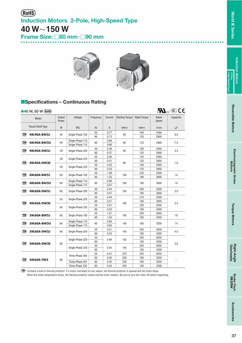
3737
Induction Motors 2-Pole, High-Speed Type
40 W�150 WFrame Size: �80 mm � �90 mm
Specifications – Continuous Rating
40 W, 60 W
Model OutputPower
W
Voltage
VAC
Frequency
Hz
Current
A
Starting Torque
mN�m
Rated Torque
mN�m
RatedSpeed
r/min
Capacitor
�FRound Shaft Type
4IK40A-BW2J 40 Single-Phase 10050 0.77
90160 2400
9.060 0.73 135 2900
4IK40A-BW2U 40Single-Phase 110
600.68
90 135 2900 7.5Single-Phase 115 0.66
4IK40A-DW2J 40 Single-Phase 20050 0.39
90160 2400
2.360 0.37 135 2900
4IK40A-DW3E36 Single-Phase 220
50 0.30
90
145 2400
1.860 0.31 120 2900
40 Single-Phase 23050 0.33 160 240060 0.32 135 2900
4IK60A-BW2J 60 Single-Phase 10050 1.09
160230 2500
1460 1.25 190 3000
4IK60A-BW2U 60Single-Phase 110
600.98
160 190 3000 10Single-Phase 115 0.97
4IK60A-DW2J 60 Single-Phase 20050 0.54
160230 2500
3.060 0.57 190 3000
4IK60A-DW3E55 Single-Phase 220
50 0.44
160
210 2500
2.560 0.51 180 3000
60 Single-Phase 23050 0.47 230 250060 0.52 190 3000
5IK60A-BW2J 60 Single-Phase 10050 1.01
140220 2650
1660 1.03 185 3200
5IK60A-BW2U 60Single-Phase 110
600.94
140 185 3200 14Single-Phase 115 0.93
5IK60A-DW2J 60 Single-Phase 20050 0.51
140220 2650
4.060 0.52 185 3200
5IK60A-DW3E 60Single-Phase 220
500.46 120
220 2650
3.060 185 3200
Single-Phase 23050
0.45 140220 2650
60 185 3200
5IK60A-TW2 60Three-Phase 200
50 0.47 270 220 2650
�60 0.40 230 185 3200
Three-Phase 220 60 0.42 230 185 3200Three-Phase 230 60 0.44 230 185 3200
: Contains a built-in thermal protector. If a motor overheats for any reason, the thermal protector is opened and the motor stops.When the motor temperature drops, the thermal protector closes and the motor restarts. Be sure to turn the motor off before inspecting.
�
�
Wo
rld K
Series
Ind
uctio
n M
oto
rsR
eversible M
oto
rsE
lec
trom
ag
ne
tic B
rak
e
Mo
tors
Torq
ue M
oto
rsR
igh
t-An
gle
Gearh
eads
Bra
ke
Pa
ck
SB5
0W
Accesso
ries2
-Po
le,
Hig
h-S
peed
Typ
e

3838
Product Line
MotorOutput Power Power Supply Voltage Model
40 W
Single-Phase 100 VAC 4IK40A-BW2JSingle-Phase 110/115 VAC 4IK40A-BW2USingle-Phase 200 VAC 4IK40A-DW2JSingle-Phase 220/230 VAC 4IK40A-DW3E
60 W
Single-Phase 100 VAC 4IK60A-BW2JSingle-Phase 110/115 VAC 4IK60A-BW2USingle-Phase 200 VAC 4IK60A-DW2JSingle-Phase 220/230 VAC 4IK60A-DW3ESingle-Phase 100 VAC 5IK60A-BW2JSingle-Phase 110/115 VAC 5IK60A-BW2USingle-Phase 200 VAC 5IK60A-DW2JSingle-Phase 220/230 VAC 5IK60A-DW3EThree-Phase 200/220/230 VAC 5IK60A-TW2
��
90 W, 150 W
Model OutputPower
W
Voltage
VAC
Frequency
Hz
Current
A
Starting Torque
mN�m
Rated Torque
mN�m
RatedSpeed
r/min
Capacitor
�FRound Shaft Type
5IK90A-BW2J 90 Single-Phase 10050 1.57
240330 2650
2860 1.85 280 3200
5IK90A-BW2U 90Single-Phase 110
601.61
240 280 3200 25Single-Phase 115 1.57
5IK90A-DW2J 90 Single-Phase 20050 0.76
240330 2650
7.060 0.90 280 3200
5IK90A-DW3E 90Single-Phase 220
50 0.70
240
330 2650
6.060 0.84 280 3200
Single-Phase 23050 0.69 330 265060 0.84 280 3200
5IK90A-TW2 90Three-Phase 200
50 0.63 500 340 2600
�60 0.55 400 285 3100
Three-Phase 220 60 0.57 400 285 3200Three-Phase 230 60 0.59 400 285 3200
5IK150A-BW2J 150 Single-Phase 10050 2.39
380560 2650
4060 2.49 460 3200
5IK150A-BW2U 150Single-Phase 110
602.12
380 460 3200 30Single-Phase 115 2.09
5IK150A-DW2J 150 Single-Phase 20050 1.16
380560 2650
1060 1.26 460 3200
5IK150A-DW3E140 Single-Phase 220
50 0.98
380
510 2650
8.060 1.07 420 3200
150 Single-Phase 23050 1.04 560 265060 1.13 460 3200
5IK150A-TW2 5IK150A-TW2T 150
Three-Phase 20050 1.11 680 550 2650
�60 0.93 570 460 3100
Three-Phase 220 60 0.97 570 460 3150Three-Phase 230 60 1.01 570 460 3200
: Contains a built-in thermal protector. If a motor overheats for any reason, the thermal protector is opened and the motor stops.When the motor temperature drops, the thermal protector closes and the motor restarts. Be sure to turn the motor off before inspecting.
�
Output Power Power Supply Voltage Model
90 W
Single-Phase 100 VAC 5IK90A-BW2JSingle-Phase 110/115 VAC 5IK90A-BW2USingle-Phase 200 VAC 5IK90A-DW2JSingle-Phase 220/230 VAC 5IK90A-DW3EThree-Phase 200/220/230 VAC 5IK90A-TW2
150 W
Single-Phase 100 VAC 5IK150A-BW2JSingle-Phase 110/115 VAC 5IK150A-BW2USingle-Phase 200 VAC 5IK150A-DW2JSingle-Phase 220/230 VAC 5IK150A-DW3EThree-Phase 200/220/230 VAC 5IK150A-TW2Three-Phase 200/220/230 VAC 5IK150A-TW2T
Wo
rld K
Series
1 W / 3 W
6 W15 W
25 W40 W
60 W90 W
2-Po
le, Hig
h-S
peed
40 W�
150 W

3939
Dimensions (Unit = mm)
40 W
Motor4IK40A-BW2J, 4IK40A-BW2U, 4IK40A-DW2J, 4IK40A-DW3EMass: 1.5 kg
4�5.5 Thru
�80
7 2
79
3285
94�0.5
22.5˚
25
Motor Leads 300 mm LengthUL Style 3271, AWG20
7
73
�0.
030
( h7)
0
8�
0.01
5( h
7)0
5 max.
Protective Earth TerminalM4
60 W
Motor4IK60A-BW2J, 4IK60A-BW2U, 4IK60A-DW2J, 4IK60A-DW3EMass: 1.8 kg
4�5.5 Thru
�80
7 232100
94�0.5
22.5˚
25
Motor Leads 300 mm LengthUL Style 3271, AWG20
�82 9
73
�0.
030
( h7)
0
10
�0.
015
( h7)
0
Protective Earth TerminalM4
5 max.
Motor5IK60A-BW2J, 5IK60A-BW2U, 5IK60A-DW2J, 5IK60A-DW3E, 5IK60A-TW2Mass: 2.5 kg
�90
89
27.537105
30
22.5˚
9
4�6.5 Thru
104�0.5
Motor Leads 300 mm LengthUL Style 3271, AWG20
83
�0.
035
( h7)
0
10�
0.01
5( h
7)0
5 max.
Protective Earth TerminalM4
90 W
Motor5IK90A-BW2J, 5IK90A-BW2U, 5IK90A-DW2J, 5IK90A-DW3E, 5IK90A-TW2Mass: 2.7 kg
4�6.5 Thru
104�0.5
�90
22.5˚
�90
30
120 377.5 2
11
Motor Leads 300 mm LengthUL Style 3271, AWG20
83
�0.
035
( h7)
0
12�
0.01
8( h
7)0
5 max.
Protective Earth TerminalM4
���
��
�
��
16.5
21.5
Detail Drawing of Protective Earth Terminal
Protective Earth TerminalM4
16.5
21.5
Detail Drawing of Protective Earth Terminal
Protective Earth TerminalM4
16.5
21.5
Detail Drawing of Protective Earth Terminal
Protective Earth TerminalM4
16.5
21.5
Detail Drawing of Protective Earth Terminal
Protective Earth TerminalM4
Wo
rld K
Series
Ind
uctio
n M
oto
rsR
eversible M
oto
rsE
lec
trom
ag
ne
tic B
rak
e
Mo
tors
Torq
ue M
oto
rsR
igh
t-An
gle
Gearh
eads
Bra
ke
Pa
ck
SB5
0W
Accesso
ries2
-Po
le,
Hig
h-S
peed
Typ
e

4040
150 W
Motor5IK150A-BW2J, 5IK150A-BW2U, 5IK150A-DW2J, 5IK150A-DW3E, 5IK150A-TW2Mass: 3.2 kg
4�6.5 Thru
104�0.5
�90
22.5˚
�90
30
135 377.5 2
11
Motor Leads 300 mm LengthUL Style 3271, AWG20
83
�0.
035
( h7)
0
12
�0.
018
( h7)
0
5 max.
Protective Earth TerminalM4
Motor5IK150A-TW2TMass: 3.3 kg
62
133
75
7.5 2
6
2543
135 37
30
11
28 max.
�90
4�6.5 Thru
104�0.5
�90
83
�0.
035
( h7)
0
12�
0.01
8( h
7)0
Use cable with a diameter of 6 � 12 mm.
Capacitor (Included with single-phase motors) Dimension No. � Dimension No. �
4.3 20
A
CB�
10B4.
54
10 6AMP#187
6
A
CB
720
10
AMP#187
4.3
4B �
15
R10
Capacitor Dimensions (mm)
ModelCapacitor
ModelA B C
Mass(g)
DimensionNo.
CapacitorCap
4IK40A-BW2J CH90CFAUL2 48 22.5 31.5 45 �
Included
4IK40A-BW2U CH75CFAUL2 48 21 31 45 �
4IK40A-DW2J CH23BFAUL 48 21 31 40 �
4IK40A-DW3E CH18BFAUL 38 21 31 35 �
4IK60A-BW2J CH140CFAUL2 58 22 35 61 �
4IK60A-BW2U CH100CFAUL2 58 21 31 50 �
4IK60A-DW2J CH30BFAUL 58 21 31 50 �
4IK60A-DW3E CH25BFAUL 48 21 31 45 �
5IK60A-BW2J CH160CFAUL2 58 23.5 37 75 �
5IK60A-BW2U CH140CFAUL2 58 22 35 61 �
5IK60A-DW2J CH40BFAUL 58 23.5 37 70 �
5IK60A-DW3E CH30BFAUL 58 21 31 50 �
5IK90A-BW2J CH280CFAUL2 58 35 50 140 �
5IK90A-BW2U CH250CFAUL2 58 35 50 140 �
5IK90A-DW2J CH70BFAUL 58 35 50 130 �
5IK90A-DW3E CH60BFAUL 58 29 41 85 �
5IK150A-BW2J CH400CFAUL2 58 41 58 180 �
5IK150A-BW2U CH300CFAUL2 58 35 50 140 �
5IK150A-DW2J CH100BFAUL 58 35 50 132 �
5IK150A-DW3E CH80BFAUL 58 35 50 130 �
��
�
�
�
�
16.5
21.5
Detail Drawing of Protective Earth Terminal
Protective Earth TerminalM4
Wo
rld K
Series
1 W / 3 W
6 W15 W
25 W40 W
60 W90 W
2-Po
le, Hig
h-S
peed
40 W�
150 W

41
Connection DiagramsThe direction of motor rotation is as viewed from the shaft end of the motor. CW represents the clockwise direction, while CCW represents the counterclockwise direction.
Counterclockwise
Clockwise
Counterclockwise
ClockwiseClockwise
Counterclockwise
Single-Phase 100 VAC, 110/115 VACSingle-Phase 200 VAC, 220/230 VAC 5IK150A-TW2T
5IK60A-TW25IK90A-TW25IK150A-TW2
Three-Phase 200/220/230 VAC
Black
RedL
N
White
GrayBlue Motor PE
CW
Capacitor
Capacitor
Black
Red
L
N
White
GrayBlue Motor PE
CCW
Red
White
BlackMotor
PE
CW
L1(R)
L2(S)
L3(T)
UVW
L1(R)L2(S)L3(T)
Motor
CW
PE
To change the rotation direction,change any two connectionsbetween R, S and T.
To change the rotation direction,change any two connectionsbetween U, V and W.
PE: Protective EarthNote:Change the direction of single-phase motor rotation only after bringing the motor to a stop. If an attempt is made to change the direction of rotation while the motor is rotating, motor may ignore reversing command or change its direction of rotation after some delay.
��
Wo
rld K
Series
Ind
uctio
n M
oto
rsR
eversible M
oto
rsE
lec
trom
ag
ne
tic B
rak
e
Mo
tors
Torq
ue M
oto
rsR
igh
t-An
gle
Gearh
eads
Bra
ke
Pa
ck
SB5
0W
Accesso
ries2
-Po
le,
Hig
h-S
peed
Typ
e
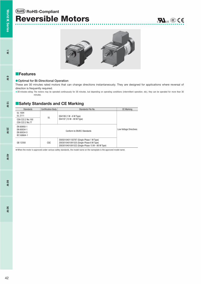
42
Reversible Motors
Features
Optimal for Bi-Directional OperationThese are 30 minutes rated motors that can change directions instantaneously. They are designed for applications where reversal of direction is frequently required.
30 minutes rating: The motors may be operated continuously for 30 minutes, but depending on operating conditions (intermittent operation, etc), they can be operated for more than 30 minutes.
Safety Standards and CE MarkingStandards Certification Body Standards File No. CE Marking
UL 1004UL 2111
ULE64199 (1 W�6 W Type)E64197 (15 W�90 W Type)
Low Voltage Directives
CSA C22.2 No.100CSA C22.2 No.77
EN 60950-1EN 60034-1EN 60034-5IEC 60664-1
Conform to EN/IEC Standards
GB 12350 CQC2005010401150787 (Single-Phase 1 W Type)2003010401091525 (Single-Phase 6 W Type)2003010401091522 (Single-Phase 15 W�90 W Type)
When the motor is approved under various safety standards, the model name on the nameplate is the approved model name.
��
✽
�
�
RoHS-Compliant
Wo
rld K
Series
1 W6 W
15 W25 W
40 W60 W
90 W

43
System Configuration
�Example of System Configuration
AC Power Supply
Mounting Brackets (Accessories)(➜ Page 121)
Gearheads (Sold separately)
Flexible Couplings (Accessories)(➜ Page 123)
Capacitor Cap✽ (Included)Insulating cap for capacitor terminal section.
Motor
Capacitor (Included)
Brake PackSB50W (Sold separately)Equipped with instantaneous stoppingfunctions, thermal protector open detectionfunctions.(➜ Page 114)
: Required under this system.: Selectable according to necessity. Oriental Motor provides.
Motor(Pinion Shaft)
4RK25GN-CW2E
(Body) (Sold separately)
Mounting BracketLong Life/Low NoiseGN-S Gearhead
4GN25S SOL4M5 MCL301012
Flexible Coupling
Right-Angle Gearheads (Sold separately)(➜ Page 108)
✽Capacitor cap is included.
The system configuration shown above is an example. Other configurations are available.
Product Number Code
Motor
5 R K 40 GN - CW 2 T Eq w e r yt i ou
� Motor Frame Size 0: 42 mm 2: 60 mm 3: 70 mm 4: 80 mm 5: 90 mm
� Motor Type R: Reversible Motor
� Series K: K Series
� Output Power (W) (Example) 40: 40 W
� Motor Shaft Type GN: GN Type Pinion Shaft GE: GE Type Pinion Shaft A: Round Shaft
� Power Supply Voltage AW: Single-Phase 100 VAC, 110/115 VAC CW: Single-Phase 200 VAC, 220/230 VAC
2, 3: RoHS-Compliant
T: Terminal Box Type
� Included Capacitor J: For Single-Phase 100 VAC, 200 VAC U: For Single-Phase 110/115 VAC E: For Single-Phase 220/230 VAC
The J, U and E at the end of the model name indicate that the unit includes a capacitor. These letters are not listed on the motor nameplate. When the motor is approved under various safety standards, the model name on the nameplate is the approved model name.(Example) Model: 5RK40GN-CW2E ➜ Motor nameplate and product approved under various safety standards: 5RK40GN-CW2
Gearhead
5 GN 50 Sq w e r
� Gearhead Frame Size 0: 42 mm 2: 60 mm 3: 70 mm 4: 80 mm 5: 90 mm
� Type of Pinion GN: GN Type Pinion GE: GE Type Pinion
� Gear Ratio (Example) 50: Gear Ratio of 1:50 10X denotes the decimal gearhead of gear ratio 1:10
�
GN Type PinionS: Long Life/Low Noise GN-S Gearhead, RoHS-Compliant K: GN-K GearheadRH: Right-Angle/Hollow Shaft Gearhead, RoHS-Compliant RA: Right-Angle/Solid Shaft Gearhead, RoHS-Compliant
GE Type PinionS: Long Life GE-S GearheadRH: Right-Angle/Hollow Shaft Gearhead, RoHS-Compliant RA: Right-Angle/Solid Shaft Gearhead, RoHS-Compliant
GN-K gearhead of frame size 42 mm complies to RoHS directive.
�
�
��
�
�
✽
Wo
rld K
Series
Ind
uctio
n M
oto
rsR
eversible M
oto
rsE
lec
trom
ag
ne
tic B
rak
e
Mo
tors
Torq
ue M
oto
rsR
igh
t-An
gle
Gearh
eads
Bra
ke
Pa
ck
SB5
0W
Accesso
ries2
-Po
le,
Hig
h-S
peed
Typ
e

44
General Specifications of Motors
1 W TypeItem Specifications
Insulation Resistance100 M� or more when 500 VDC megger is applied between the windings and the frame after rated motor operation under normal ambient temperature and humidity.
Dielectric StrengthSufficient to withstand 1.5 kV at 50 Hz or 60 Hz applied between the windings and the frame for 1 minute after rated motor operation under normal ambient temperature and humidity.
Temperature RiseTemperature rise of windings are 75˚C or less measured by the resistance change method after rated motor operation under normal ambient temperature and humidity, with connecting a gearhead or equivalent heat radiation plate✽.
Insulation Class UL/CSA standards: Class A (105˚C), EN standards: Class E (120˚C)Overheat Protection Impedance protectedAmbient Temperature �10˚C��40˚C (nonfreezing)Ambient Humidity 85% or less (noncondensing)Degree of Protection IP20
6 W�90 W TypeItem Specifications
Insulation Resistance100 M� or more when 500 VDC megger is applied between the windings and the frame after rated motor operation under normal ambient temperature and humidity.
Dielectric StrengthSufficient to withstand 1.5 kV at 50 Hz or 60 Hz applied between the windings and the frame for 1 minute after rated motor operation under normal ambient temperature and humidity.
Temperature Rise
Temperature rise of windings are 80˚C or less measured by the resistance change method after rated motor operation under normal ambient temperature and humidity, with connecting a gearhead or equivalent heat radiation plate✽.However, a heat radiation plate that is 200�200 mm with a thickness of 5 mm is necessary even when the gearhead is connected for the 90 W type (200 VAC, 220/230 VAC).
Insulation Class Class B (130˚C)
Overheat Protection6 W type has impedance protection.All others have built-in thermal protector (automatic return type) Operating temperature; open: 130˚C�5˚C, close: 82˚C�15˚C
Ambient TemperatureSingle-phase 100 VAC, Single-phase 200 VAC: �10˚C��50˚C (nonfreezing)Other voltage: �10˚C��40˚C (nonfreezing)
Ambient Humidity 85% or less (noncondensing)
Degree of ProtectionLead Wire Type: IP20Terminal Box Type: 6 W Type IP65 (excluding the installation surface of the round shaft type) 25 W, 40 W, 60 W, 90 W Type IP40
Heat radiation plate (Material: Aluminum)
Motor Type Size (mm) Thickness (mm)1 W Type 80�80
5
6 W Type 115�11515 W Type 125�12525 W Type 135�13540 W Type 165�165
60 W Type90 W Type (100 VAC, 110/115 VAC)
200�200
90 W Type (200 VAC, 220/230 VAC) 200�200 10
��
�
✽
Wo
rld K
Series
1 W6 W
15 W25 W
40 W60 W
90 W

45
Reversible Motors
1 WFrame Size: �42 mm
Specifications – 30 Minutes Rating Model
Lead Wire TypeOutputPower
Voltage Frequency Current Starting Torque Rated TorqueRatedSpeed
Capacitor
Pinion Shaft Type Round Shaft Type W VAC Hz A mN�m mN�m r/min �F
0RK1GN-AW2J 0RK1A-AW2J 1 Single-Phase 10050 0.120
810 1000
1.860 0.125 8 1200
0RK1GN-AW3U 0RK1A-AW3U 1Single-Phase 110
600.090
8 8 1200 1.2Single-Phase 115 0.095
0RK1GN-CW2J 0RK1A-CW2J 1 Single-Phase 20050 0.066
810 1000
0.4560 0.069 8 1200
Values shown for rated torque and starting torque are measured for operation without the friction brake installed.The J and U at the end of the model name indicate that the unit includes a capacitor. These letters are not listed on the motor nameplate.When the motor is approved under various safety standards, the model name on the nameplate is the approved model name.
: Impedance protected
�
��
Product Line
Motor
TypeModel
Pinion Shaft Type Round Shaft Type
Lead Wire0RK1GN-AW2J 0RK1A-AW2J0RK1GN-AW3U 0RK1A-AW3U0RK1GN-CW2J 0RK1A-CW2J
��
(Gearhead sold separately)
Gearhead (Sold Separately) Type Gearhead Model Gear Ratio
Parallel Shaft 0GN�K3, 3.6, 5, 6, 7.5, 9, 12.5, 15, 18, 25, 30, 36, 50, 60, 75,
90, 100, 120, 150, 180
Enter the gear ratio in the box (�) within the model name.
�
�
Gearmotor – Torque TableGearheads are sold separately. Decimal gearheads are not available.Enter the gear ratio in the box (�) within the model name.A colored background indicates gear shaft rotation in the same direction as the motor shaft, while the others rotate in the opposite direction.The speed is calculated by dividing the motor's synchronous speed (50 Hz: 1500 r/min, 60 Hz: 1800 r/min) by the gear ratio.The actual speed is 2 - 33% less than the displayed value, depending on the size of the load.
50 Hz Unit = N�m
ModelSpeedr/min
500 416 300 250 200 166 120 100 83 60 50 41 30 25 20 16 15 12.5 10 8.3
Motor/Gearhead
Gear Ratio 3 3.6 5 6 7.5 9 12.5 15 18 25 30 36 50 60 75 90 100 120 150 180
0RK1GN-AW2J0RK1GN-CW2J 0GN�K 0.024 0.029 0.041 0.049 0.061 0.073 0.091 0.11 0.13 0.17 0.2 0.24 0.33 0.4 0.44 0.53 0.59 0.71 0.89 1
60 Hz Unit = N�m
ModelSpeedr/min
600 500 360 300 240 200 144 120 100 72 60 50 36 30 24 20 18 15 12 10
Motor/Gearhead
Gear Ratio 3 3.6 5 6 7.5 9 12.5 15 18 25 30 36 50 60 75 90 100 120 150 180
0RK1GN-AW2J0RK1GN-AW3U0RK1GN-CW2J
0GN�K 0.019 0.023 0.032 0.039 0.049 0.058 0.073 0.088 0.11 0.13 0.16 0.19 0.26 0.32 0.35 0.42 0.47 0.57 0.71 0.85
����
�
�
�
Wo
rld K
Series
Ind
uctio
n M
oto
rsR
eversible M
oto
rsE
lec
trom
ag
ne
tic B
rak
e
Mo
tors
Torq
ue M
oto
rsR
igh
t-An
gle
Gearh
eads
Bra
ke
Pa
ck
SB5
0W
Accesso
ries2
-Po
le,
Hig
h-S
peed
Typ
e
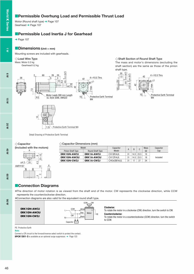
46
Permissible Overhung Load and Permissible Thrust LoadMotor (Round shaft type) ➜ Page 107Gearhead ➜ Page 107
Permissible Load Inertia J for Gearhead➜ Page 107
Dimensions (Unit = mm)
Mounting screws are included with gearheads.
�
�
�
Lead Wire TypeMass: Motor 0.3 kg Gearhead 0.2 kg
48�0.542
10
8 18
263
4.512
5
Motor Leads 300 mm LengthUL Style 3266, AWG2216.5
28
7.5
2
0
5�0.
012
( h7)
206042
4�3.5 Thru
Protective Earth TerminalM4
7 m
ax.
�
Capacitor(Included with the motors)
4.3 20
A
CB�
10B4.
54
10 6AMP#187
�
Shaft Section of Round Shaft TypeThe mass and motor's dimensions (excluding the shaft section) are the same as those of the pinion shaft type.
201.5
48�0.5
4�3.5 Thru
5�
0.01
2 (h7
)0
42
42
10
0
37.6
�0.
025 (
h7)
Protective Earth TerminalM4
7 m
ax.
�
Capacitor Dimensions (mm)Model Capacitor
ModelA B C
Mass(g)
CapacitorCapPinion Shaft Type Round Shaft Type
0RK1GN-AW2J 0RK1A-AW2J CH18FAUL 31 14.5 23.5 18Included0RK1GN-AW3U 0RK1A-AW3U CH12FAUL 31 14.5 23.5 18
0RK1GN-CW2J 0RK1A-CW2J CH045BFAUL 31 17 27 24
�
Connection DiagramsThe direction of motor rotation is as viewed from the shaft end of the motor. CW represents the clockwise direction, while CCW represents the counterclockwise direction.Connection diagrams are also valid for the equivalent round shaft type.
0RK1GN-AW2J0RK1GN-AW3U0RK1GN-CW2J
Clockwise:To rotate the motor in a clockwise (CW) direction, turn the switch to CW.Counterclockwise:To rotate the motor in a counterclockwise (CCW) direction, turn the switchto CCW.
CCW
Motor
CW
Black
White
CW
CCWL
N
RedPE
Capacitor
PE: Protective EarthNote:Connect a CR circuit to the forward/reverse select switch to protect the contact.EPCR1201-2 is available as an optional surge suppressor. ➜ Page 123
��
�
10
7.25
Detail Drawing of Protective Earth Terminal
Protective Earth Terminal M4
Wo
rld K
Series
1 W6 W
15 W25 W
40 W60 W
90 W
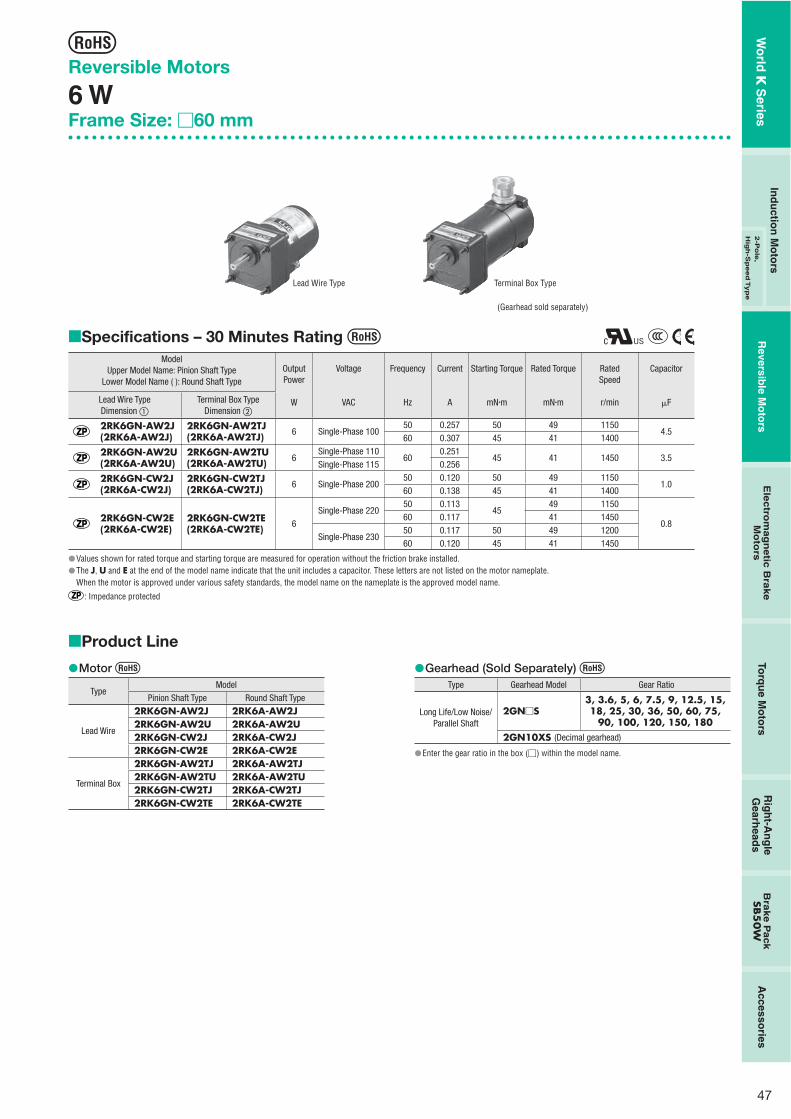
47
Reversible Motors
6 WFrame Size: �60 mm
Specifications – 30 Minutes Rating Model
Upper Model Name: Pinion Shaft TypeLower Model Name ( ): Round Shaft Type
OutputPower
W
Voltage
VAC
Frequency
Hz
Current
A
Starting Torque
mN�m
Rated Torque
mN�m
RatedSpeed
r/min
Capacitor
�FLead Wire TypeDimension �
Terminal Box TypeDimension �
2RK6GN-AW2J(2RK6A-AW2J)
2RK6GN-AW2TJ(2RK6A-AW2TJ) 6 Single-Phase 100
50 0.257 50 49 11504.5
60 0.307 45 41 1400
2RK6GN-AW2U(2RK6A-AW2U)
2RK6GN-AW2TU(2RK6A-AW2TU) 6
Single-Phase 11060
0.25145 41 1450 3.5
Single-Phase 115 0.256
2RK6GN-CW2J(2RK6A-CW2J)
2RK6GN-CW2TJ(2RK6A-CW2TJ) 6 Single-Phase 200
50 0.120 50 49 11501.0
60 0.138 45 41 1400
2RK6GN-CW2E(2RK6A-CW2E)
2RK6GN-CW2TE(2RK6A-CW2TE) 6
Single-Phase 22050 0.113
4549 1150
0.860 0.117 41 1450
Single-Phase 23050 0.117 50 49 120060 0.120 45 41 1450
Values shown for rated torque and starting torque are measured for operation without the friction brake installed.The J, U and E at the end of the model name indicate that the unit includes a capacitor. These letters are not listed on the motor nameplate.When the motor is approved under various safety standards, the model name on the nameplate is the approved model name.
: Impedance protected
�
��
Lead Wire Type Terminal Box Type
(Gearhead sold separately)
Product Line
Motor
TypeModel
Pinion Shaft Type Round Shaft Type
Lead Wire
2RK6GN-AW2J 2RK6A-AW2J 2RK6GN-AW2U 2RK6A-AW2U 2RK6GN-CW2J 2RK6A-CW2J 2RK6GN-CW2E 2RK6A-CW2E
Terminal Box
2RK6GN-AW2TJ 2RK6A-AW2TJ 2RK6GN-AW2TU 2RK6A-AW2TU 2RK6GN-CW2TJ 2RK6A-CW2TJ 2RK6GN-CW2TE 2RK6A-CW2TE
�� Gearhead (Sold Separately)
Type Gearhead Model Gear Ratio
Long Life/Low Noise/ Parallel Shaft
2GN�S3, 3.6, 5, 6, 7.5, 9, 12.5, 15, 18, 25, 30, 36, 50, 60, 75,
90, 100, 120, 150, 1802GN10XS (Decimal gearhead)
Enter the gear ratio in the box (�) within the model name.
�
�
Wo
rld K
Series
Ind
uctio
n M
oto
rsR
eversible M
oto
rsE
lec
trom
ag
ne
tic B
rak
e
Mo
tors
Torq
ue M
oto
rsR
igh
t-An
gle
Gearh
eads
Bra
ke
Pa
ck
SB5
0W
Accesso
ries2
-Po
le,
Hig
h-S
peed
Typ
e

48
Gearmotor – Torque TableGearheads and decimal gearheads are sold separately.Enter the code that represents the terminal box type "T" in the box (��) within the model name.Enter the gear ratio in the box (�) within the model name.A colored background indicates gear shaft rotation in the same direction as the motor shaft, while the others rotate in the opposite direction.The speed is calculated by dividing the motor's synchronous speed (50 Hz: 1500 r/min, 60 Hz: 1800 r/min) by the gear ratio.The actual speed is 2 - 20% less than the displayed value, depending on the size of the load.To reduce the speed beyond the gear ratio in the table, attach a decimal gearhead (gear ratio: 10) between the gearhead and the motor. In that case, the permissible torque is 3 N�m.
50 Hz Unit = N�m
ModelSpeedr/min
500 416 300 250 200 166 120 100 83 60 50 41 30 25 20 16 15 12.5 10 8.3
Motor/Gearhead
Gear Ratio 3 3.6 5 6 7.5 9 12.5 15 18 25 30 36 50 60 75 90 100 120 150 180
2RK6GN-AW2��J2RK6GN-CW2��J2RK6GN-CW2��E
2GN�S 0.12 0.14 0.20 0.24 0.30 0.36 0.50 0.60 0.71 0.89 1.1 1.3 1.6 1.9 2.4 2.9 3 3 3 3
60 Hz Unit = N�m
ModelSpeedr/min
600 500 360 300 240 200 144 120 100 72 60 50 36 30 24 20 18 15 12 10
Motor/Gearhead
Gear Ratio 3 3.6 5 6 7.5 9 12.5 15 18 25 30 36 50 60 75 90 100 120 150 180
2RK6GN-AW2��J2RK6GN-AW2��U2RK6GN-CW2��J2RK6GN-CW2��E
2GN�S 0.10 0.12 0.17 0.20 0.25 0.30 0.42 0.50 0.60 0.75 0.90 1.1 1.4 1.6 2.0 2.4 2.7 3 3 3
Permissible Overhung Load and Permissible Thrust LoadMotor (Round shaft type) ➜ Page 107Gearhead ➜ Page 107
Permissible Load Inertia J for Gearhead➜ Page 107
Dimensions (Unit = mm)
Mounting screws are included with gearheads.
�����
�
�
�
�
�
�
�
Lead Wire Type �Mass: Motor 0.7 kg Gearhead 0.4 kg
4�4.5 Thru
Motor Leads 300 mm LengthUL Style 3271, AWG20
75 L1 325
10
12
24
60
60
7
7 70�0.5
22.5˚
60
8 �
0.01
5( h
7)0
Protective Earth TerminalM4
5 max.
�Motor Model Gearhead Model Gear Ratio L1
2RK6GN-AW2��
2RK6GN-CW2��2GN�S
3�18 30
25�180 40
Specify the type of the capacitor to be included by entering J, U or E in the box (��) within the model name.Enter the gear ratio in the box (�) within the model name.
15.5
21.5
Detail Drawing of Protective Earth Terminal
Protective Earth TerminalM4
�
Wo
rld K
Series
1 W6 W
15 W25 W
40 W60 W
90 W

49
Shaft Section of Round Shaft TypeThe mass and motor's dimensions (excluding the shaft section)are the same as those of the pinion shaft type.
224
22.5˚
4�4.5 Thru
70�0.5
�60
54
�0.
030
( h7)
0
6 �
0.01
2( h
7)0
Protective Earth Terminal M4(Lead Wire Type Only)
5 max.
� Decimal GearheadCan be connected to GN pinion shaft type.2GN10XSMass: 0.2 kg
38.526 12.5
2 4�4.5 Thru
70�0.5
�60
54
�0.
030(
h7)
0
�
Terminal Box Type �Mass: Motor 0.9 kg Gearhead 0.4 kg
62
46.5
91.5
1157
32 m
ax.
L15 12
24
32
10
7
4�4.5 Thru
70�0.5
8�
0.01
5( h
7)0
60
60
Use cable with a diameter of 8 � 12 mm.
�
�
Capacitor(Included with the motors)
4.3 20
A
CB�
10B4.
54
10 6AMP#187
� Capacitor Dimensions (mm)
ModelUpper Model Name: Pinion Shaft Type
Lower Model Name ( ): Round Shaft TypeCapacitor
ModelA B C
Mass(g)
CapacitorCap
Lead Wire Type Terminal Box Type
2RK6GN-AW2J(2RK6A-AW2J)
2RK6GN-AW2TJ(2RK6A-AW2TJ) CH45FAUL2 37 18 27 30
Included
2RK6GN-AW2U(2RK6A-AW2U)
2RK6GN-AW2TU(2RK6A-AW2TU) CH35FAUL2 31 17 27 25
2RK6GN-CW2J(2RK6A-CW2J)
2RK6GN-CW2TJ(2RK6A-CW2TJ) CH10BFAUL 37 18 27 30
2RK6GN-CW2E(2RK6A-CW2E)
2RK6GN-CW2TE(2RK6A-CW2TE) CH08BFAUL 31 17 27 20
�
Connection DiagramsThe direction of motor rotation is as viewed from the shaft end of the motor. CW represents the clockwise direction, while CCW represents the counterclockwise direction.Connection diagrams are also valid for the equivalent round shaft type.Specify the type of the capacitor to be included by entering J, U or E in the box (�) within the model name.
2RK6GN-AW2T�
2RK6GN-CW2T�
Terminal Box Type
ClockwiseTo rotate the motor in a clockwise (CW) direction, turn the switch to CW.CounterclockwiseTo rotate the motor in a counterclockwise (CCW) direction, turn the switch to CCW.
2RK6GN-AW2�
2RK6GN-CW2�
Lead Wire Type
ClockwiseTo rotate the motor in a clockwise (CW) direction, turn the switch to CW.CounterclockwiseTo rotate the motor in a counterclockwise (CCW) direction, turn the switch to CCW.
CCW CW
L
NMotor
Capacitor PE
CW
CCW
U1U2Z2
CCW
Motor
CW
Black
White
CW
CCWL
N
RedPE
Capacitor
PE: Protective EarthNote:Connect a CR circuit to the forward/reverse select switch to protect the contact.EPCR1201-2 is available as an optional surge suppressor. ➜ Page 123
��
��
Motor Model Gearhead Model Gear Ratio L1
2RK6GN-AW2T��
2RK6GN-CW2T��2GN�S
3�18 30
25�180 40
Specify the type of the capacitor to be included by entering J, U or E in the box (��) within the model name.Enter the gear ratio in the box (�) within the model name.
�
Wo
rld K
Series
Ind
uctio
n M
oto
rsR
eversible M
oto
rsE
lec
trom
ag
ne
tic B
rak
e
Mo
tors
Torq
ue M
oto
rsR
igh
t-An
gle
Gearh
eads
Bra
ke
Pa
ck
SB5
0W
Accesso
ries2
-Po
le,
Hig
h-S
peed
Typ
e

50
Reversible Motors
15 WFrame Size: �70 mm
Specifications – 30 Minutes Rating Model
Lead Wire TypeOutputPower
Voltage Frequency Current Starting Torque Rated TorqueRatedSpeed
Capacitor
Pinion Shaft Type Round Shaft Type W VAC Hz A mN�m mN�m r/min �F
3RK15GN-AW2J 3RK15A-AW2J 15 Single-Phase 10050 0.41
100125 1200
7.560 0.50 105 1450
3RK15GN-AW2U 3RK15A-AW2U 15Single-Phase 110
600.41
100 105 1450 6.0Single-Phase 115 0.41
3RK15GN-CW2J 3RK15A-CW2J 15 Single-Phase 20050 0.21
100125 1200
1.860 0.24 105 1450
3RK15GN-CW2E 3RK15A-CW2E 15Single-Phase 220
50 0.20
100
125 1200
1.560 0.21 105 1450
Single-Phase 23050 0.20 125 120060 0.21 105 1450
Values shown for rated torque and starting torque are measured for operation without the friction brake installed.The J, U and E at the end of the model name indicate that the unit includes a capacitor. These letters are not listed on the motor nameplate.When the motor is approved under various safety standards, the model name on the nameplate is the approved model name.
: Contains a built-in thermal protector. If a motor overheats for any reason, the thermal protector is opened and the motor stops.When the motor temperature drops, the thermal protector closes and the motor restarts. Be sure to turn the motor off before inspecting.
�
��
(Gearhead sold separately)
Product Line
Motor
TypeModel
Pinion Shaft Type Round Shaft Type
Lead Wire
3RK15GN-AW2J 3RK15A-AW2J3RK15GN-AW2U 3RK15A-AW2U3RK15GN-CW2J 3RK15A-CW2J3RK15GN-CW2E 3RK15A-CW2E
�� Gearhead (Sold Separately)
Type Gearhead Model Gear Ratio
Long Life/Low Noise/ Parallel Shaft
3GN�S3, 3.6, 5, 6, 7.5, 9, 12.5, 15,
18, 25, 30, 36, 50, 60, 75, 90, 100, 120, 150, 180
3GN10XS (Decimal gearhead)
Enter the gear ratio in the box (�) within the model name.
�
�
Wo
rld K
Series
1 W6 W
15 W25 W
40 W60 W
90 W
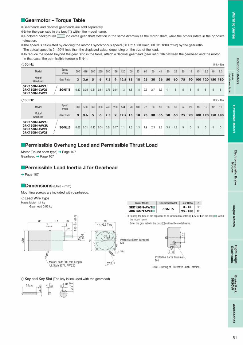
51
Gearmotor – Torque TableGearheads and decimal gearheads are sold separately.Enter the gear ratio in the box (�) within the model name.A colored background indicates gear shaft rotation in the same direction as the motor shaft, while the others rotate in the opposite direction.The speed is calculated by dividing the motor's synchronous speed (50 Hz: 1500 r/min, 60 Hz: 1800 r/min) by the gear ratio.The actual speed is 2 - 20% less than the displayed value, depending on the size of the load.To reduce the speed beyond the gear ratio in the table, attach a decimal gearhead (gear ratio: 10) between the gearhead and the motor. In that case, the permissible torque is 5 N�m.
50 Hz Unit = N�m
ModelSpeedr/min
500 416 300 250 200 166 120 100 83 60 50 41 30 25 20 16 15 12.5 10 8.3
Motor/Gearhead
Gear Ratio 3 3.6 5 6 7.5 9 12.5 15 18 25 30 36 50 60 75 90 100 120 150 180
3RK15GN-AW2J3RK15GN-CW2J3RK15GN-CW2E
3GN�S 0.30 0.36 0.51 0.61 0.76 0.91 1.3 1.5 1.8 2.3 2.7 3.3 4.1 5 5 5 5 5 5 5
60 Hz Unit = N�m
ModelSpeedr/min
600 500 360 300 240 200 144 120 100 72 60 50 36 30 24 20 18 15 12 10
Motor/Gearhead
Gear Ratio 3 3.6 5 6 7.5 9 12.5 15 18 25 30 36 50 60 75 90 100 120 150 180
3RK15GN-AW2J3RK15GN-AW2U3RK15GN-CW2J3RK15GN-CW2E
3GN�S 0.26 0.31 0.43 0.51 0.64 0.77 1.1 1.3 1.5 1.9 2.3 2.8 3.5 4.2 5 5 5 5 5 5
Permissible Overhung Load and Permissible Thrust LoadMotor (Round shaft type) ➜ Page 107Gearhead ➜ Page 107
Permissible Load Inertia J for Gearhead➜ Page 107
Dimensions (Unit = mm)
Mounting screws are included with gearheads.
����
�
�
�
�
�
�
�
Lead Wire TypeMass: Motor 1.1 kg Gearhead 0.55 kg
69
807
L1 325
25
15 30
82�0.5
Motor Leads 300 mm LengthUL Style 3271, AWG20
70
70
4�5.5 Thru
22.5˚
10
�0.
015
( h7)
0
Protective Earth TerminalM4
5 max.
�Motor Model Gearhead Model Gear Ratio L1
3RK15GN-AW2��
3RK15GN-CW2��3GN�S
3�18 32
25�180 42
Specify the type of the capacitor to be included by entering J, U or E in the box (��) within the model name.Enter the gear ratio in the box (�) within the model name.
16.5
21.5
Detail Drawing of Protective Earth Terminal
Protective Earth TerminalM4
�
Key and Key Slot (The key is included with the gearhead)
25�0.2 4 0�0.040
2.5
0�0.
1
4�0.
03 0
4�0.03 0
�
Wo
rld K
Series
Ind
uctio
n M
oto
rsR
eversible M
oto
rsE
lec
trom
ag
ne
tic B
rak
e
Mo
tors
Torq
ue M
oto
rsR
igh
t-An
gle
Gearh
eads
Bra
ke
Pa
ck
SB5
0W
Accesso
ries2
-Po
le,
Hig
h-S
peed
Typ
e

52
Decimal GearheadCan be connected to GN pinion shaft type.3GN10XSMass: 0.3 kg
4330 13
2 4�5.5 Thru
82�0.5
64
�0.
030
( h7)
0 �70
�
Capacitor(Included with the motors)
4.3 20
A
CB�
10B4.
54
10 6AMP#187
� Capacitor Dimensions (mm)Model Capacitor
ModelA B C
Mass(g)
CapacitorCapPinion Shaft Type Round Shaft Type
3RK15GN-AW2J 3RK15A-AW2J CH75CFAUL2 48 21 31 45
Included3RK15GN-AW2U 3RK15A-AW2U CH60CFAUL2 38 21 31 40
3RK15GN-CW2J 3RK15A-CW2J CH18BFAUL 38 21 31 35
3RK15GN-CW2E 3RK15A-CW2E CH15BFAUL 38 21 31 35
�
Connection DiagramsThe direction of motor rotation is as viewed from the shaft end of the motor. CW represents the clockwise direction, while CCW represents the counterclockwise direction.Connection diagrams are also valid for the equivalent round shaft type.Specify the type of the capacitor to be included by entering J, U or E in the box (�) within the model name.
3RK15GN-AW2�
3RK15GN-CW2�
Clockwise:To rotate the motor in a clockwise (CW) direction, turn the switch to CW.Counterclockwise:To rotate the motor in a counterclockwise (CCW) direction, turn the switchto CCW.
CCW
Motor
CW
Black
White
CW
CCWL
N
RedPE
Capacitor
PE: Protective EarthNote:Connect a CR circuit to the forward/reverse select switch to protect the contact.EPCR1201-2 is available as an optional surge suppressor. ➜ Page 123
��
��
Shaft Section of Round Shaft TypeThe mass and motor's dimensions (excluding the shaft section)are the same as those of the pinion shaft type.
4�5.5 Thru232
82�0.5
�70
22.5˚
64
�0.
030
( h7)
0
6 �0.
012
( h7)
0
5 max.
Protective Earth TerminalM4
�
Wo
rld K
Series
1 W6 W
15 W25 W
40 W60 W
90 W

53
Reversible Motors
25 WFrame Size: �80 mm
Specifications – 30 Minutes Rating Model
Upper Model Name: Pinion Shaft TypeLower Model Name ( ): Round Shaft Type
OutputPower
W
Voltage
VAC
Frequency
Hz
Current
A
Starting Torque
mN�m
Rated Torque
mN�m
RatedSpeed
r/min
Capacitor
�FLead Wire TypeDimension �
Terminal Box TypeDimension �
4RK25GN-AW2J(4RK25A-AW2J)
4RK25GN-AW2TJ(4RK25A-AW2TJ) 25 Single-Phase 100
50 0.59 160 205 120010
60 0.69 140 170 1450
4RK25GN-AW2U(4RK25A-AW2U)
4RK25GN-AW2TU(4RK25A-AW2TU) 25
Single-Phase 11060 0.56 140 170 1450 8.0
Single-Phase 115
4RK25GN-CW2J(4RK25A-CW2J)
4RK25GN-CW2TJ(4RK25A-CW2TJ) 25 Single-Phase 200
50 0.32 160 205 12003.0
60 0.40 140 170 1450
4RK25GN-CW2E(4RK25A-CW2E)
4RK25GN-CW2TE(4RK25A-CW2TE) 25
Single-Phase 22050 0.29
140205 1200
2.560 0.35 170 1450
Single-Phase 23050 0.30 160 205 120060 0.35 140 170 1450
Values shown for rated torque and starting torque are measured for operation without the friction brake installed.The J, U and E at the end of the model name indicate that the unit includes a capacitor. These letters are not listed on the motor nameplate. When the motor is approved under various safety standards, the model name on the nameplate is the approved model name.
: Contains a built-in thermal protector. If a motor overheats for any reason, the thermal protector is opened and the motor stops.When the motor temperature drops, the thermal protector closes and the motor restarts. Be sure to turn the motor off before inspecting.
�
��
Product Line
Motor
TypeModel
Pinion Shaft Type Round Shaft Type
Lead Wire
4RK25GN-AW2J 4RK25A-AW2J4RK25GN-AW2U 4RK25A-AW2U4RK25GN-CW2J 4RK25A-CW2J4RK25GN-CW2E 4RK25A-CW2E
Terminal Box
4RK25GN-AW2TJ 4RK25A-AW2TJ4RK25GN-AW2TU 4RK25A-AW2TU4RK25GN-CW2TJ 4RK25A-CW2TJ4RK25GN-CW2TE 4RK25A-CW2TE
�� Gearhead/Right-Angle Gearhead (Sold Separately)
Type Gearhead Model Gear Ratio
Long Life/Low Noise/ Parallel Shaft
4GN�S3, 3.6, 5, 6, 7.5, 9, 12.5, 15, 18, 25, 30, 36, 50, 60, 75,
90, 100, 120, 150, 1804GN10XS (Decimal gearhead)
Right-Angle/Hollow Shaft
4GN�RH3, 3.6, 5, 6, 7.5, 9, 12.5, 15, 18, 25, 30, 36, 50, 60, 75,
90, 100, 120, 150, 180
Right-Angle/Solid Shaft
4GN�RA3, 3.6, 5, 6, 7.5, 9, 12.5, 15, 18, 25, 30, 36, 50, 60, 75,
90, 100, 120, 150, 180
Enter the gear ratio in the box (�) within the model name.
�
�
Right-angle gearheads (hollow shaft or solid shaft) can be combined.Right-Angle Gearheads ➜ Page 108
(Gearhead sold separately)
Terminal Box TypeLead Wire Type
Wo
rld K
Series
Ind
uctio
n M
oto
rsR
eversible M
oto
rsE
lec
trom
ag
ne
tic B
rak
e
Mo
tors
Torq
ue M
oto
rsR
igh
t-An
gle
Gearh
eads
Bra
ke
Pa
ck
SB5
0W
Accesso
ries2
-Po
le,
Hig
h-S
peed
Typ
e

54
Lead Wire Type �Mass: Motor 1.5 kg Gearhead 0.65 kg
4�5.5 Thru
79
L185 326
94�0.5
7
25
34
15
80
Motor Leads 300 mm LengthUL Style 3271, AWG20
80
22.5˚
10
�0.
015
( h7)
0
5 max.
Protective Earth TerminalM4
�
Gearmotor – Torque TableGearheads and decimal gearheads are sold separately.Enter the code that represents the terminal box type "T" in the box (��) within the model name.Enter the gear ratio in the box (�) within the model name.A colored background indicates gear shaft rotation in the same direction as the motor shaft, while the others rotate in the opposite direction.The speed is calculated by dividing the motor's synchronous speed (50 Hz: 1500 r/min, 60 Hz: 1800 r/min) by the gear ratio.The actual speed is 2 - 20% less than the displayed value, depending on the size of the load.To reduce the speed beyond the gear ratio in the table, attach a decimal gearhead (gear ratio: 10) between the gearhead and the motor.In that case, the permissible torque is 8 N�m. When a gearhead of 1/25�1/36 is connected, the value for permissible torque is 6 N�m.
50 Hz Unit = N�m
ModelSpeedr/min
500 416 300 250 200 166 120 100 83 60 50 41 30 25 20 16 15 12.5 10 8.3
Motor/Gearhead
Gear Ratio 3 3.6 5 6 7.5 9 12.5 15 18 25 30 36 50 60 75 90 100 120 150 180
4RK25GN-AW2��J4RK25GN-CW2��J4RK25GN-CW2��E
4GN�S 0.50 0.60 0.83 1.0 1.2 1.5 2.1 2.5 3.0 3.7 4.5 5.4 6.8 8 8 8 8 8 8 8
60 Hz Unit = N�m
ModelSpeedr/min
500 416 300 250 200 166 120 100 83 60 50 41 30 25 20 16 15 12.5 10 8.3
Motor/Gearhead
Gear Ratio 3 3.6 5 6 7.5 9 12.5 15 18 25 30 36 50 60 75 90 100 120 150 180
4RK25GN-AW2��J4RK25GN-AW2��U4RK25GN-CW2��J4RK25GN-CW2��E
4GN�S 0.41 0.50 0.69 0.83 1.0 1.2 1.7 2.1 2.5 3.1 3.7 4.5 5.6 6.7 8 8 8 8 8 8
Permissible Overhung Load and Permissible Thrust LoadMotor (Round shaft type) ➜ Page 107Gearhead ➜ Page 107
Permissible Load Inertia J for Gearhead➜ Page 107
Dimensions (Unit = mm)
Mounting screws are included with gearheads.
�����
�
�
�
�
�
�
�
Motor Model Gearhead Model Gear Ratio L1
4RK25GN-AW2��
4RK25GN-CW2��4GN�S
3�18 32
25�180 42.5
Specify the type of the capacitor to be included by entering J, U or E in the box (��) within the model name.Enter the gear ratio in the box (�) within the model name.
16.5
21.5
Detail Drawing of Protective Earth Terminal
Protective Earth TerminalM4
�
Wo
rld K
Series
1 W6 W
15 W25 W
40 W60 W
90 W
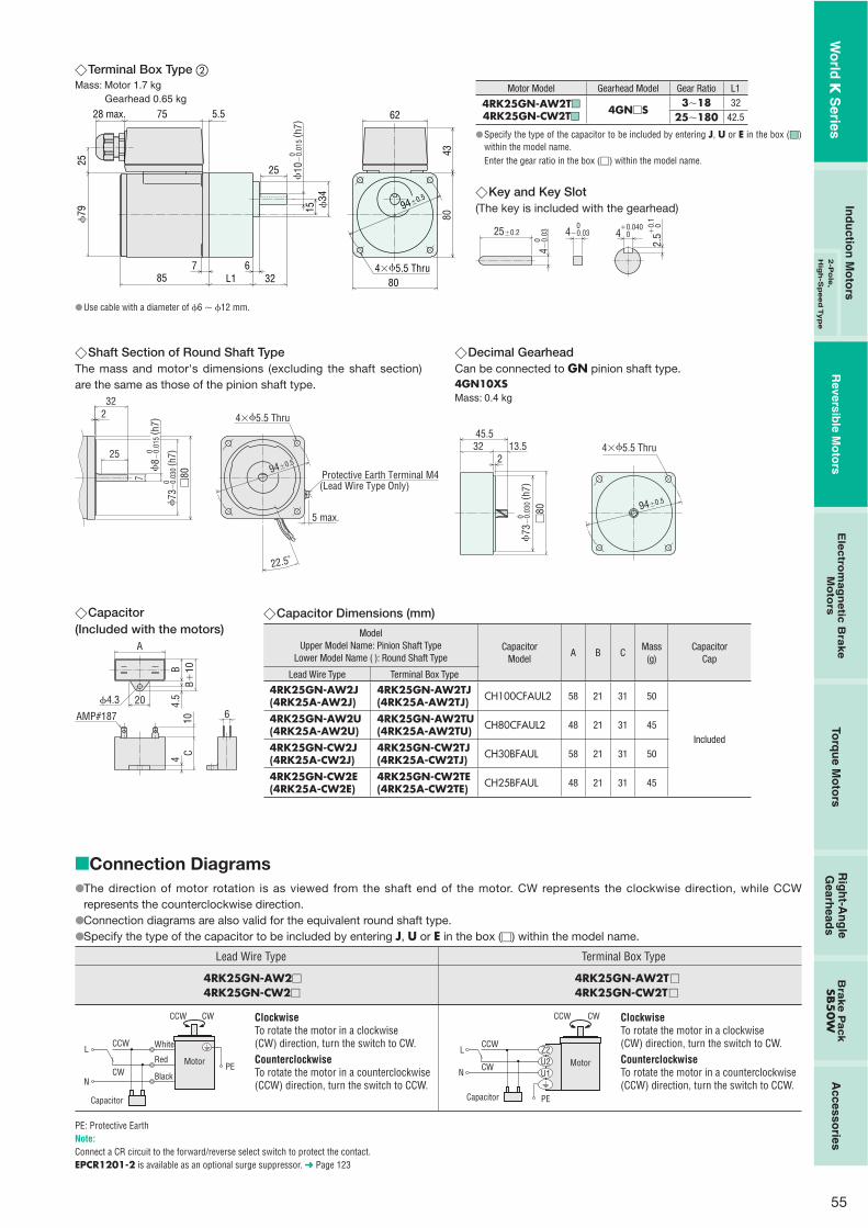
55
Terminal Box Type �Mass: Motor 1.7 kg Gearhead 0.65 kg
4�5.5 Thru
28 max. 75
79
5.5
85 L16
327
25
34
15
80
62
43
94�0.5
25
80
10
�0.
015
( h7)
0
Use cable with a diameter of 6 � 12 mm.
�
�
Motor Model Gearhead Model Gear Ratio L1
4RK25GN-AW2T��
4RK25GN-CW2T��4GN�S
3�18 32
25�180 42.5
Specify the type of the capacitor to be included by entering J, U or E in the box (��)within the model name.Enter the gear ratio in the box (�) within the model name.
Key and Key Slot (The key is included with the gearhead)
25�0.2 4 0�0.040
2.5
0�0.
1
4�0.
03 0
4�0.03 0
�
�
Shaft Section of Round Shaft TypeThe mass and motor's dimensions (excluding the shaft section) are the same as those of the pinion shaft type.
4�5.5 Thru232
94�0.525
7
�80
22.5˚
73
�0.
030
( h7)
0
8 �
0.01
5( h
7)0
5 max.
Protective Earth Terminal M4(Lead Wire Type Only)
�
Capacitor(Included with the motors)
4.3 20
A
CB�
10B4.
54
10 6AMP#187
�
Decimal GearheadCan be connected to GN pinion shaft type.4GN10XSMass: 0.4 kg
45.532 13.5
2
�80
4�5.5 Thru
94�0.5
73
�0.
030
( h7)
0
�
Capacitor Dimensions (mm)
ModelUpper Model Name: Pinion Shaft Type
Lower Model Name ( ): Round Shaft TypeCapacitor
ModelA B C
Mass(g)
CapacitorCap
Lead Wire Type Terminal Box Type
4RK25GN-AW2J(4RK25A-AW2J)
4RK25GN-AW2TJ(4RK25A-AW2TJ) CH100CFAUL2 58 21 31 50
Included
4RK25GN-AW2U(4RK25A-AW2U)
4RK25GN-AW2TU(4RK25A-AW2TU) CH80CFAUL2 48 21 31 45
4RK25GN-CW2J(4RK25A-CW2J)
4RK25GN-CW2TJ(4RK25A-CW2TJ) CH30BFAUL 58 21 31 50
4RK25GN-CW2E(4RK25A-CW2E)
4RK25GN-CW2TE(4RK25A-CW2TE) CH25BFAUL 48 21 31 45
�
Connection DiagramsThe direction of motor rotation is as viewed from the shaft end of the motor. CW represents the clockwise direction, while CCW represents the counterclockwise direction.Connection diagrams are also valid for the equivalent round shaft type.Specify the type of the capacitor to be included by entering J, U or E in the box (�) within the model name.
4RK25GN-AW2�
4RK25GN-CW2�
Lead Wire Type
4RK25GN-AW2T�
4RK25GN-CW2T�
Terminal Box Type
ClockwiseTo rotate the motor in a clockwise (CW) direction, turn the switch to CW.CounterclockwiseTo rotate the motor in a counterclockwise (CCW) direction, turn the switch to CCW.
ClockwiseTo rotate the motor in a clockwise (CW) direction, turn the switch to CW.CounterclockwiseTo rotate the motor in a counterclockwise (CCW) direction, turn the switch to CCW.
CCW CW
L
NMotor
Capacitor PE
CW
CCW
U1U2Z2
CCW
Motor
CW
Black
White
CW
CCWL
N
RedPE
Capacitor
PE: Protective EarthNote:Connect a CR circuit to the forward/reverse select switch to protect the contact.EPCR1201-2 is available as an optional surge suppressor. ➜ Page 123
��
��
Wo
rld K
Series
Ind
uctio
n M
oto
rsR
eversible M
oto
rsE
lec
trom
ag
ne
tic B
rak
e
Mo
tors
Torq
ue M
oto
rsR
igh
t-An
gle
Gearh
eads
Bra
ke
Pa
ck
SB5
0W
Accesso
ries2
-Po
le,
Hig
h-S
peed
Typ
e

56
Reversible Motors
40 WFrame Size: �90 mm
Specifications – 30 Minutes Rating Model
Upper Model Name: Pinion Shaft TypeLower Model Name ( ): Round Shaft Type
OutputPower
W
Voltage
VAC
Frequency
Hz
Current
A
Starting Torque
mN�m
Rated Torque
mN�m
RatedSpeed
r/min
Capacitor
�FLead Wire TypeDimension �
Terminal Box TypeDimension �
5RK40GN-AW2J(5RK40A-AW2J)
5RK40GN-AW2TJ(5RK40A-AW2TJ) 40 Single-Phase 100
50 0.91 300 315 125016
60 1.09 260 270 1450
5RK40GN-AW2U(5RK40A-AW2U)
5RK40GN-AW2TU(5RK40A-AW2TU) 40
Single-Phase 11060
0.88260 270 1450 12
Single-Phase 115 0.87
5RK40GN-CW2J(5RK40A-CW2J)
5RK40GN-CW2TJ(5RK40A-CW2TJ) 40 Single-Phase 200
50 0.46 270 315 12504.0
60 0.55 260 260 1500
5RK40GN-CW2E(5RK40A-CW2E)
5RK40GN-CW2TE(5RK40A-CW2TE) 40
Single-Phase 22050 0.43 270 315 1250
3.560 0.48 260 260 1500
Single-Phase 23050 0.43 270 315 125060 0.48 260 260 1500
Values shown for rated torque and starting torque are measured for operation without the friction brake installed.The J, U and E at the end of the model name indicate that the unit includes a capacitor. These letters are not listed on the motor nameplate. When the motor is approved under various safety standards, the model name on the nameplate is the approved model name.
: Contains a built-in thermal protector. If a motor overheats for any reason, the thermal protector is opened and the motor stops.When the motor temperature drops, the thermal protector closes and the motor restarts. Be sure to turn the motor off before inspecting.
�
��
Product Line
Motor
TypeModel
Pinion Shaft Type Round Shaft Type
Lead Wire
5RK40GN-AW2J 5RK40A-AW2J 5RK40GN-AW2U 5RK40A-AW2U 5RK40GN-CW2J 5RK40A-CW2J 5RK40GN-CW2E 5RK40A-CW2E
Terminal Box
5RK40GN-AW2TJ 5RK40A-AW2TJ 5RK40GN-AW2TU 5RK40A-AW2TU 5RK40GN-CW2TJ 5RK40A-CW2TJ 5RK40GN-CW2TE 5RK40A-CW2TE
�� Gearhead/Right-Angle Gearhead (Sold Separately)
Type Gearhead Model Gear Ratio
Long Life/Low Noise/ Parallel Shaft
5GN�S3, 3.6, 5, 6, 7.5, 9, 12.5, 15, 18, 25, 30, 36, 50, 60, 75,
90, 100, 120, 150, 1805GN10XS (Decimal gearhead)
Right-Angle/Hollow Shaft
5GN�RH3, 3.6, 5, 6, 7.5, 9, 12.5, 15, 18, 25, 30, 36, 50, 60, 75,
90, 100, 120, 150, 180
Right-Angle/Solid Shaft
5GN�RA3, 3.6, 5, 6, 7.5, 9, 12.5, 15, 18, 25, 30, 36, 50, 60, 75,
90, 100, 120, 150, 180
Enter the gear ratio in the box (�) within the model name.
�
�
Lead Wire Type Terminal Box Type
Right-angle gearheads (hollow shaft or solid shaft) can be combined.Right-Angle Gearheads ➜ Page 108
(Gearhead sold separately)
Wo
rld K
Series
1 W6 W
15 W25 W
40 W60 W
90 W

57
Gearmotor – Torque TableGearheads and decimal gearheads are sold separately.Enter the code that represents the terminal box type "T" in the box (��) within the model name.Enter the gear ratio in the box (�) within the model name.A colored background indicates gear shaft rotation in the same direction as the motor shaft, while the others rotate in the opposite direction.The speed is calculated by dividing the motor's synchronous speed (50 Hz: 1500 r/min, 60 Hz: 1800 r/min) by the gear ratio.The actual speed is 2 - 20% less than the displayed value, depending on the size of the load.To reduce the speed beyond the gear ratio in the table, attach a decimal gearhead (gear ratio: 10) between the gearhead and the motor. In that case, the permissible torque is 10 N�m.
50 Hz Unit = N�m
ModelSpeedr/min
500 416 300 250 200 166 120 100 83 60 50 41 30 25 20 16 15 12.5 10 8.3
Motor/Gearhead
Gear Ratio 3 3.6 5 6 7.5 9 12.5 15 18 25 30 36 50 60 75 90 100 120 150 180
5RK40GN-AW2��J5RK40GN-CW2��J5RK40GN-CW2��E
5GN�S 0.77 0.92 1.3 1.5 1.9 2.3 3.2 3.8 4.6 5.7 6.9 8.3 10 10 10 10 10 10 10 10
60 Hz Unit = N�m
ModelSpeedr/min
600 500 360 300 240 200 144 120 100 72 60 50 36 30 24 20 18 15 12 10
Motor/Gearhead
Gear Ratio 3 3.6 5 6 7.5 9 12.5 15 18 25 30 36 50 60 75 90 100 120 150 180
5RK40GN-AW2��J5RK40GN-AW2��U 5GN�S 0.66 0.79 1.1 1.3 1.6 2.0 2.7 3.3 3.9 4.9 5.9 7.1 8.9 10 10 10 10 10 10 10
5RK40GN-CW2��J5RK40GN-CW2��E 5GN�S 0.63 0.76 1.1 1.3 1.6 1.9 2.6 3.2 3.8 4.7 5.7 6.8 8.6 10 10 10 10 10 10 10
Permissible Overhung Load and Permissible Thrust LoadMotor (Round shaft type) ➜ Page 107Gearhead ➜ Page 107
Permissible Load Inertia J for Gearhead➜ Page 107
Dimensions (Unit = mm)
Mounting screws are included with gearheads.
�����
�
�
�
�
�
�
�
Lead Wire Type �Mass: Motor 2.5 kg Gearhead 1.5 kg
4�6.5 Thru
89
105 L14
327.5
18 36
25
90
Motor Leads 300 mm LengthUL Style 3271, AWG20
104�0.5
90
22.5
12
�0.
018
( h7)
0
5 max.
Protective Earth TerminalM4
�16
.5
21.5
Detail Drawing of Protective Earth Terminal
Protective Earth TerminalM4
Motor Model Gearhead Model Gear Ratio L1
5RK40GN-AW2��
5RK40GN-CW2��5GN�S
3�18 42
25�180 60
Specify the type of the capacitor to be included by entering J, U or E in the box (��) within the model name.Enter the gear ratio in the box (�) within the model name.
�
Wo
rld K
Series
Ind
uctio
n M
oto
rsR
eversible M
oto
rsE
lec
trom
ag
ne
tic B
rak
e
Mo
tors
Torq
ue M
oto
rsR
igh
t-An
gle
Gearh
eads
Bra
ke
Pa
ck
SB5
0W
Accesso
ries2
-Po
le,
Hig
h-S
peed
Typ
e

58
Terminal Box Type �Mass: Motor 2.6 kg Gearhead 1.5 kg
4�6.5 Thru
28 max. 75 6
89
105 L14
327.5
18
36
62
90
104�0.5
25
25
4390
12
�0.
018
( h7)
0
Use cable with a diameter of 6 � 12 mm.
�
�
Shaft Section of Round Shaft TypeThe mass and motor's dimensions (excluding the shaft section) are the same as those of the pinion shaft type.
237
30
9
4�6.5 Thru
104�0.5
�90
22.5˚
10
�0.
015
( h7)
0
83
�0.
035
( h7)
0
5 max.
Protective Earth Terminal M4(Lead Wire Type Only)
� Decimal GearheadCan be connected to GN pinion shaft type.5GN10XSMass: 0.6 kg
37 1855
2
�90
4�6.5 Thru
104�0.5
83
�0.
035
( h7)
0
�
Key and Key Slot (The key is included with the gearhead)
25�0.2 4 0�0.040
2.5
0�0.
1
4�0.
03 0
4�0.03 0
�
Motor Model Gearhead Model Gear Ratio L1
5RK40GN-AW2T��
5RK40GN-CW2T��5GN�S
3�18 42
25�180 60
Specify the type of the capacitor to be included by entering J, U or E in the box (��) within the model name.Enter the gear ratio in the box (�) within the model name.
�
Capacitor (Included with the motors) Dimension No. � Dimension No. �
4.3 20
A
CB �
10B4.
54
10 6AMP#187
6
A
CB
720
10
AMP#187
4.3
4B �
15
R10
Capacitor Dimensions (mm)
ModelUpper Model Name: Pinion Shaft Type
Lower Model Name ( ): Round Shaft TypeCapacitor
ModelA B C
Mass(g)
DimensionNo.
CapacitorCap
Lead Wire Type Terminal Box Type
5RK40GN-AW2J(5RK40A-AW2J)
5RK40GN-AW2TJ(5RK40A-AW2TJ) CH160CFAUL2 58 23.5 37 75 �
Included
5RK40GN-AW2U(5RK40A-AW2U)
5RK40GN-AW2TU(5RK40A-AW2TU) CH120CFAUL2 58 22 35 60 �
5RK40GN-CW2J(5RK40A-CW2J)
5RK40GN-CW2TJ(5RK40A-CW2TJ) CH40BFAUL 58 23.5 37 70 �
5RK40GN-CW2E(5RK40A-CW2E)
5RK40GN-CW2TE(5RK40A-CW2TE) CH35BFAUL 58 22 35 55 �
�
�
Wo
rld K
Series
1 W6 W
15 W25 W
40 W60 W
90 W

59
Connection DiagramsThe direction of motor rotation is as viewed from the shaft end of the motor. CW represents the clockwise direction, while CCW represents the counterclockwise direction.Connection diagrams are also valid for the equivalent round shaft type.Specify the type of the capacitor to be included by entering J, U or E in the box (�) within the model name.
5RK40GN-AW2�
5RK40GN-CW2�
Lead Wire Type
5RK40GN-AW2T�
5RK40GN-CW2T�
Terminal Box Type
ClockwiseTo rotate the motor in a clockwise (CW) direction, turn the switch to CW.CounterclockwiseTo rotate the motor in a counterclockwise (CCW) direction, turn the switch to CCW.
ClockwiseTo rotate the motor in a clockwise (CW) direction, turn the switch to CW.CounterclockwiseTo rotate the motor in a counterclockwise (CCW) direction, turn the switch to CCW.
CCW CW
L
NMotor
Capacitor PE
CW
CCW
U1U2Z2
CCW
Motor
CW
CW
CCWL
N
PE
Capacitor
Black
White
Red
PE: Protective EarthNote:Connect a CR circuit to the forward/reverse select switch to protect the contact.EPCR1201-2 is available as an optional surge suppressor. ➜ Page 123
��
��
Wo
rld K
Series
Ind
uctio
n M
oto
rsR
eversible M
oto
rsE
lec
trom
ag
ne
tic B
rak
e
Mo
tors
Torq
ue M
oto
rsR
igh
t-An
gle
Gearh
eads
Bra
ke
Pa
ck
SB5
0W
Accesso
ries2
-Po
le,
Hig
h-S
peed
Typ
e
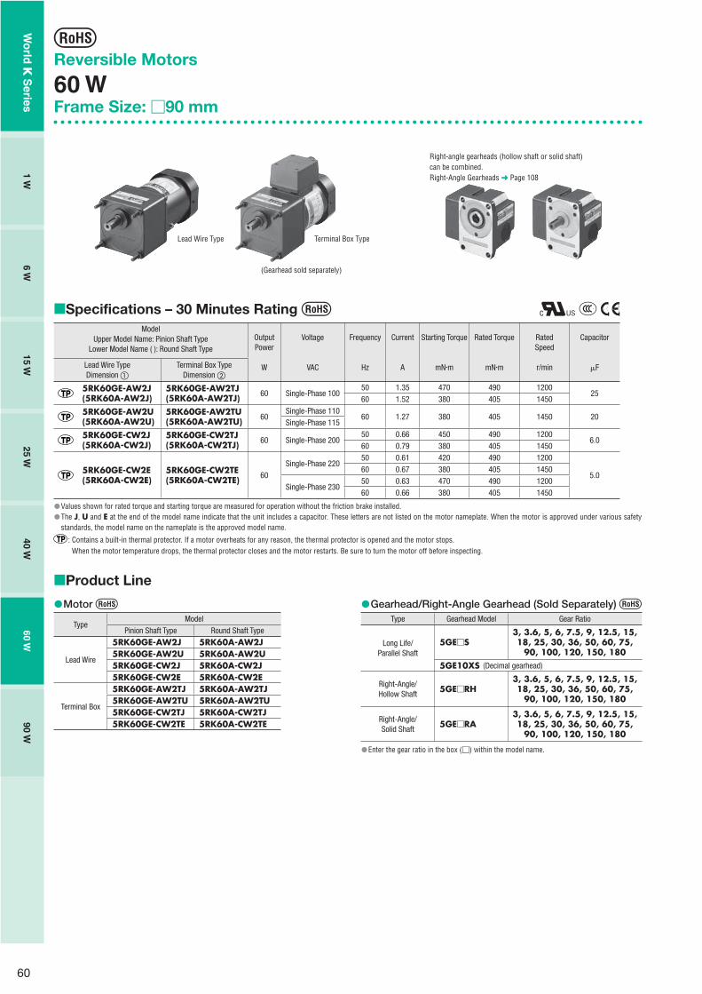
60
Reversible Motors
60 WFrame Size: �90 mm
Specifications – 30 Minutes Rating Model
Upper Model Name: Pinion Shaft TypeLower Model Name ( ): Round Shaft Type
OutputPower
W
Voltage
VAC
Frequency
Hz
Current
A
Starting Torque
mN�m
Rated Torque
mN�m
RatedSpeed
r/min
Capacitor
�FLead Wire TypeDimension �
Terminal Box TypeDimension �
5RK60GE-AW2J(5RK60A-AW2J)
5RK60GE-AW2TJ(5RK60A-AW2TJ) 60 Single-Phase 100
50 1.35 470 490 120025
60 1.52 380 405 1450
5RK60GE-AW2U(5RK60A-AW2U)
5RK60GE-AW2TU(5RK60A-AW2TU) 60
Single-Phase 11060 1.27 380 405 1450 20
Single-Phase 115
5RK60GE-CW2J(5RK60A-CW2J)
5RK60GE-CW2TJ(5RK60A-CW2TJ) 60 Single-Phase 200
50 0.66 450 490 12006.0
60 0.79 380 405 1450
5RK60GE-CW2E(5RK60A-CW2E)
5RK60GE-CW2TE(5RK60A-CW2TE) 60
Single-Phase 22050 0.61 420 490 1200
5.060 0.67 380 405 1450
Single-Phase 23050 0.63 470 490 120060 0.66 380 405 1450
Values shown for rated torque and starting torque are measured for operation without the friction brake installed.The J, U and E at the end of the model name indicate that the unit includes a capacitor. These letters are not listed on the motor nameplate. When the motor is approved under various safety standards, the model name on the nameplate is the approved model name.
: Contains a built-in thermal protector. If a motor overheats for any reason, the thermal protector is opened and the motor stops.When the motor temperature drops, the thermal protector closes and the motor restarts. Be sure to turn the motor off before inspecting.
�
��
Product Line
Motor
TypeModel
Pinion Shaft Type Round Shaft Type
Lead Wire
5RK60GE-AW2J 5RK60A-AW2J 5RK60GE-AW2U 5RK60A-AW2U 5RK60GE-CW2J 5RK60A-CW2J 5RK60GE-CW2E 5RK60A-CW2E
Terminal Box
5RK60GE-AW2TJ 5RK60A-AW2TJ 5RK60GE-AW2TU 5RK60A-AW2TU 5RK60GE-CW2TJ 5RK60A-CW2TJ 5RK60GE-CW2TE 5RK60A-CW2TE
�� Gearhead/Right-Angle Gearhead (Sold Separately)
Type Gearhead Model Gear Ratio
Long Life/Parallel Shaft
5GE�S3, 3.6, 5, 6, 7.5, 9, 12.5, 15, 18, 25, 30, 36, 50, 60, 75,
90, 100, 120, 150, 1805GE10XS (Decimal gearhead)
Right-Angle/Hollow Shaft
5GE�RH3, 3.6, 5, 6, 7.5, 9, 12.5, 15, 18, 25, 30, 36, 50, 60, 75,
90, 100, 120, 150, 180
Right-Angle/Solid Shaft
5GE�RA3, 3.6, 5, 6, 7.5, 9, 12.5, 15, 18, 25, 30, 36, 50, 60, 75,
90, 100, 120, 150, 180
Enter the gear ratio in the box (�) within the model name.
�
�
Lead Wire Type Terminal Box Type
Right-angle gearheads (hollow shaft or solid shaft) can be combined.Right-Angle Gearheads ➜ Page 108
(Gearhead sold separately)
Wo
rld K
Series
1 W6 W
15 W25 W
40 W60 W
90 W

61
Gearmotor – Torque TableGearheads and decimal gearheads are sold separately.Enter the code that represents the terminal box type "T" in the box (��) within the model name.Enter the gear ratio in the box (�) within the model name.A colored background indicates gear shaft rotation in the same direction as the motor shaft, while the others rotate in the opposite direction.The speed is calculated by dividing the motor's synchronous speed (50 Hz: 1500 r/min, 60 Hz: 1800 r/min) by the gear ratio.The actual speed is 2 - 20% less than the displayed value, depending on the size of the load.To reduce the speed beyond the gear ratio in the table, attach a decimal gearhead (gear ratio: 10) between the gearhead and the motor. In that case, the permissible torque is 20 N�m.
50 Hz Unit = N�m
ModelSpeedr/min
500 416 300 250 200 166 120 100 83 60 50 41 30 25 20 16 15 12.5 10 8.3
Motor/Gearhead
Gear Ratio 3 3.6 5 6 7.5 9 12.5 15 18 25 30 36 50 60 75 90 100 120 150 180
5RK60GE-AW2m��J5RK60GE-CW2m��J5RK60GE-CW2��E
5GE�S 1.2 1.4 2.0 2.4 3.0 3.6 4.5 5.4 6.4 8.1 9.7 11.6 16.2 19.4 20 20 20 20 20 20
60 Hz Unit = N�m
ModelSpeedr/min
600 500 360 300 240 200 144 120 100 72 60 50 36 30 24 20 18 15 12 10
Motor/Gearhead
Gear Ratio 3 3.6 5 6 7.5 9 12.5 15 18 25 30 36 50 60 75 90 100 120 150 180
5RK60GE-AW2��J5RK60GE-AW2��U5RK60GE-CW2��J5RK60GE-CW2��E
5GE�S 0.98 1.2 1.6 2.0 2.5 3.0 3.7 4.4 5.3 6.7 8.0 9.6 13.4 16.0 17.9 20 20 20 20 20
Permissible Overhung Load and Permissible Thrust LoadMotor (Round shaft type) ➜ Page 107Gearhead ➜ Page 107
Permissible Load Inertia J for Gearhead➜ Page 107
Dimensions (Unit = mm)
Mounting screws are included with gearheads.
�����
�
�
�
�
�
�
�
Lead Wire Type �Mass: Motor 2.7 kg Gearhead 1.5 kg
�90
120 6577.5
18 34
90
38
Motor Leads 300 mm LengthUL Style 3271, AWG20
4�6.5 Thru
104�0.5
15
�0.
018
( h7)
0
22.5˚
90
M5 10 Deep
5 max.
25
17
29�0.5
Protective Earth TerminalM4
�16
.5
21.5
Detail Drawing of Protective Earth Terminal
Protective Earth TerminalM4
Wo
rld K
Series
Ind
uctio
n M
oto
rsR
eversible M
oto
rsE
lec
trom
ag
ne
tic B
rak
e
Mo
tors
Torq
ue M
oto
rsR
igh
t-An
gle
Gearh
eads
Bra
ke
Pa
ck
SB5
0W
Accesso
ries2
-Po
le,
Hig
h-S
peed
Typ
e

62
Key and Key Slot (The key is included with the gearhead)
25�0.2 5 0�0.040
3 0�0.
1
5�0.
03 0
5�0.03 0
�
Decimal GearheadCan be connected to GE pinion shaft type.5GE10XSMass: 0.6 kg
6140 21
24�10.8 Thru
104�0.5
83�
0.03
5( h
7)0
�90
�Shaft Section of Round Shaft TypeThe mass and motor's dimensions (excluding the shaft section) are the same as those of the pinion shaft type.
4�6.5 Thru
104�0.530
372
11 �90
22.5˚
12
�0.
018
( h7)
0
83
�0.
035
( h7)
0
5 max.
Protective Earth Terminal M4(Lead Wire Type Only)
�
Terminal Box Type �Mass: Motor 2.8 kg Gearhead 1.5 kg
�90
120 6577.5
18 34
9038 4�6.5 Thru
104�0.5
28 max. 75 6
43
25
62
15
�0.
018
( h7)
0
90
M5 10 Deep25
17
29�0.5
Use cable with a diameter of 6 � 12 mm.
�
�
Capacitor(Included with the motors)
6
A
CB
720
10
AMP#187
4.3
4B �
15
R10
� Capacitor Dimensions (mm)
ModelUpper Model Name: Pinion Shaft Type
Lower Model Name ( ): Round Shaft TypeCapacitor
ModelA B C
Mass(g)
CapacitorCap
Lead Wire Type Terminal Box Type
5RK60GE-AW2J(5RK60A-AW2J)
5RK60GE-AW2TJ(5RK60A-AW2TJ) CH250CFAUL2 58 35 50 140
Included
5RK60GE-AW2U(5RK60A-AW2U)
5RK60GE-AW2TU(5RK60A-AW2TU) CH200CFAUL2 58 29 41 95
5RK60GE-CW2J(5RK60A-CW2J)
5RK60GE-CW2TJ(5RK60A-CW2TJ) CH60BFAUL 58 29 41 85
5RK60GE-CW2E(5RK60A-CW2E)
5RK60GE-CW2TE(5RK60A-CW2TE) CH50BFAUL 58 29 41 85
�
Connection DiagramsThe direction of motor rotation is as viewed from the shaft end of the motor. CW represents the clockwise direction, while CCW represents the counterclockwise direction.Connection diagrams are also valid for the equivalent round shaft type.Specify the type of the capacitor to be included by entering J, U or E in the box (�) within the model name.
5RK60GE-AW2�
5RK60GE-CW2�
Lead Wire Type
5RK60GE-AW2T�
5RK60GE-CW2T�
Terminal Box Type
ClockwiseTo rotate the motor in a clockwise (CW) direction, turn the switch to CW.CounterclockwiseTo rotate the motor in a counterclockwise (CCW) direction, turn the switch to CCW.
ClockwiseTo rotate the motor in a clockwise (CW) direction, turn the switch to CW.CounterclockwiseTo rotate the motor in a counterclockwise (CCW) direction, turn the switch to CCW.
CCW CW
L
NMotor
Capacitor PE
CW
CCW
U1U2Z2
CCW
Motor
CW
Black
White
CW
CCWL
N
RedPE
Capacitor
PE: Protective EarthNote:Connect a CR circuit to the forward/reverse select switch to protect the contact.EPCR1201-2 is available as an optional surge suppressor. ➜ Page 123
��
��
Wo
rld K
Series
1 W6 W
15 W25 W
40 W60 W
90 W

63
Reversible Motors
90 WFrame Size: �90 mm
Specifications – 30 Minutes Rating Model
Upper Model Name: Pinion Shaft TypeLower Model Name ( ): Round Shaft Type
OutputPower
W
Voltage
VAC
Frequency
Hz
Current
A
Starting Torque
mN�m
Rated Torque
mN�m
RatedSpeed
r/min
Capacitor
�FLead Wire TypeDimension �
Terminal Box TypeDimension �
5RK90GE-AW2J(5RK90A-AW2J)
5RK90GE-AW2TJ(5RK90A-AW2TJ) 90 Single-Phase 100
50 1.85 630 700 125035
60 2.16 590 585 1500
5RK90GE-AW2U(5RK90A-AW2U)
5RK90GE-AW2TU(5RK90A-AW2TU) 90
Single-Phase 11060
1.87590 585 1500 30
Single-Phase 115 1.86
5RK90GE-CW2J(5RK90A-CW2J)
5RK90GE-CW2TJ(5RK90A-CW2TJ) 90 Single-Phase 200
50 0.91 600 730 12008.0
60 1.09 590 605 1450
5RK90GE-CW3E(5RK90A-CW3E)
5RK90GE-CW3TE(5RK90A-CW3TE) 90
Single-Phase 22050 0.83 600 730 1200
7.060 0.96 590 605 1450
Single-Phase 23050 0.83 600 730 120060 0.95 590 605 1450
Values shown for rated torque and starting torque are measured for operation without the friction brake installed.The J, U and E at the end of the model name indicate that the unit includes a capacitor. These letters are not listed on the motor nameplate. When the motor is approved under various safety standards, the model name on the nameplate is the approved model name.
: Contains a built-in thermal protector. If a motor overheats for any reason, the thermal protector is opened and the motor stops.When the motor temperature drops, the thermal protector closes and the motor restarts. Be sure to turn the motor off before inspecting.
�
��
Product Line
Motor
TypeModel
Pinion Shaft Type Round Shaft Type
Lead Wire
5RK90GE-AW2J 5RK90A-AW2J 5RK90GE-AW2U 5RK90A-AW2U 5RK90GE-CW2J 5RK90A-CW2J 5RK90GE-CW3E 5RK90A-CW3E
Terminal Box
5RK90GE-AW2TJ 5RK90A-AW2TJ 5RK90GE-AW2TU 5RK90A-AW2TU 5RK90GE-CW2TJ 5RK90A-CW2TJ 5RK90GE-CW3TE 5RK90A-CW3TE
�� Gearhead/Right-Angle Gearhead (Sold Separately)
Type Gearhead Model Gear Ratio
Long Life/ Parallel Shaft
5GE�S3, 3.6, 5, 6, 7.5, 9, 12.5, 15, 18, 25, 30, 36, 50, 60, 75,
90, 100, 120, 150, 1805GE10XS (Decimal gearhead)
Right-Angle/Hollow Shaft
5GE�RH3, 3.6, 5, 6, 7.5, 9, 12.5, 15, 18, 25, 30, 36, 50, 60, 75,
90, 100, 120, 150, 180
Right-Angle/Solid Shaft
5GE�RA3, 3.6, 5, 6, 7.5, 9, 12.5, 15, 18, 25, 30, 36, 50, 60, 75,
90, 100, 120, 150, 180
Enter the gear ratio in the box (�) within the model name.
�
�
Right-angle gearheads (hollow shaft or solid shaft) can be combined.Right-Angle Gearheads ➜ Page 108
Lead Wire Type Terminal Box Type
(Gearhead sold separately)
Wo
rld K
Series
Ind
uctio
n M
oto
rsR
eversible M
oto
rsE
lec
trom
ag
ne
tic B
rak
e
Mo
tors
Torq
ue M
oto
rsR
igh
t-An
gle
Gearh
eads
Bra
ke
Pa
ck
SB5
0W
Accesso
ries2
-Po
le,
Hig
h-S
peed
Typ
e

64
Dimensions (Unit = mm)
Mounting screws are included with gearheads.
�
Lead Wire Type �Mass: Motor 3.2 kg Gearhead 1.5 kg
�90
135 65 387
18 34
90
7.5
Motor Leads 300 mm LengthUL Style 3271, AWG20
4�6.5 Thru
90
104�0.5
15
�0.
018
( h7)
0
22.5˚
M5 10 Deep
5 max.
25
17
29�0.5
Protective Earth TerminalM4
�
Gearmotor – Torque TableGearheads and decimal gearheads are sold separately.Enter the code that represents the terminal box type "T" in the box (��) within the model name.Enter the gear ratio in the box (�) within the model name.A colored background indicates gear shaft rotation in the same direction as the motor shaft, while the others rotate in the opposite direction.The speed is calculated by dividing the motor's synchronous speed (50 Hz: 1500 r/min, 60 Hz: 1800 r/min) by the gear ratio.The actualspeed is 2 - 20% less than the displayed value, depending on the size of the load.To reduce the speed beyond the gear ratio in the table, attach a decimal gearhead (gear ratio: 10) between the gearhead and the motor. In that case, the permissible torque is 20 N�m.
50 Hz Unit = N�m
ModelSpeedr/min
500 416 300 250 200 166 120 100 83 60 50 41 30 25 20 16 15 12.5 10 8.3
Motor/Gearhead
Gear Ratio 3 3.6 5 6 7.5 9 12.5 15 18 25 30 36 50 60 75 90 100 120 150 180
5RK90GE-AW2m��J 5GE�S 1.7 2.0 2.8 3.4 4.3 5.1 6.4 7.7 9.2 11.6 13.9 16.6 20 20 20 20 20 20 20 20
5RK90GE-CW2��J5RK90GE-CW3��E 5GE�S 1.8 2.1 3.0 3.5 4.4 5.3 6.7 8.0 9.6 12.0 14.5 17.3 20 20 20 20 20 20 20 20
60 Hz Unit = N�m
ModelSpeedr/min
600 500 360 300 240 200 144 120 100 72 60 50 36 30 24 20 18 15 12 10
Motor/Gearhead
Gear Ratio 3 3.6 5 6 7.5 9 12.5 15 18 25 30 36 50 60 75 90 100 120 150 180
5RK90GE-AW2��J5RK90GE-AW2��U 5GE�S 1.4 1.7 2.4 2.8 3.6 4.3 5.3 6.4 7.7 9.7 11.6 13.9 19.3 20 20 20 20 20 20 20
5RK90GE-CW2��J5RK90GE-CW3��E 5GE�S 1.5 1.8 2.5 2.9 3.7 4.4 5.5 6.6 7.9 10.0 12.0 14.4 20 20 20 20 20 20 20 20
Permissible Overhung Load and Permissible Thrust LoadMotor (Round shaft type) ➜ Page 107Gearhead ➜ Page 107
Permissible Load Inertia J for Gearhead➜ Page 107
�����
�
�
�
�
�
�
16.5
21.5
Detail Drawing of Protective Earth Terminal
Protective Earth TerminalM4
Wo
rld K
Series
1 W6 W
15 W25 W
40 W60 W
90 W

65
Key and Key Slot (The key is included with the gearhead)
25�0.2 5 0�0.040
3 0�0.
1
5�0.
03 0
5�0.03 0
�
Decimal GearheadCan be connected to GE pinion shaft type.5GE10XSMass: 0.6 kg
6140 21
24�10.8 Thru
104�0.5
83
�0.
035
( h7)
0
�90
�Shaft Section of Round Shaft TypeThe mass and motor's dimensions (excluding the shaft section) are the same as those of the pinion shaft type.
4�6.5 Thru
104�0.530
372
11 �90
22.5˚
12
�0.
018
( h7)
0
83
�0.
035
( h7)
0
5 max.
Protective Earth Terminal M4(Lead Wire Type Only)
�
Terminal Box Type �Mass: Motor 3.3 kg Gearhead 1.5 kg
�90
135 65 387
18 34
7.5
28 max. 75 6
25
90
104�0.5
43
62
4�6.5 Thru
90
15
�0.
018
( h7)
0 M5 10 Deep25
17
29�0.5
Use cable with a diameter of 6 � 12 mm.
�
�
Capacitor(Included with the motors)
6
A
CB
720
10
AMP#187
4.3
4B �
15
R10
� Capacitor Dimensions (mm)
ModelUpper Model Name: Pinion Shaft Type
Lower Model Name ( ): Round Shaft TypeCapacitor
ModelA B C
Mass(g)
CapacitorCap
Lead Wire Type Terminal Box Type
5RK90GE-AW2J(5RK90A-AW2J)
5RK90GE-AW2TJ(5RK90A-AW2TJ) CH350CFAUL2 58 41 58 180
Included
5RK90GE-AW2U(5RK90A-AW2U)
5RK90GE-AW2TU(5RK90A-AW2TU) CH300CFAUL2 58 35 50 140
5RK90GE-CW2J(5RK90A-CW2J)
5RK90GE-CW2TJ(5RK90A-CW2TJ) CH80BFAUL 58 35 50 130
5RK90GE-CW3E(5RK90A-CW3E)
5RK90GE-CW3TE(5RK90A-CW3TE) CH70BFAUL 58 35 50 130
�
Wo
rld K
Series
Ind
uctio
n M
oto
rsR
eversible M
oto
rsE
lec
trom
ag
ne
tic B
rak
e
Mo
tors
Torq
ue M
oto
rsR
igh
t-An
gle
Gearh
eads
Bra
ke
Pa
ck
SB5
0W
Accesso
ries2
-Po
le,
Hig
h-S
peed
Typ
e

66
Connection DiagramsThe direction of motor rotation is as viewed from the shaft end of the motor. CW represents the clockwise direction, while CCW represents the counterclockwise direction.Connection diagrams are also valid for the equivalent round shaft type.Specify the type of the capacitor to be included by entering J or U in the box (�) within the model name.
5RK90GE-AW2�
5RK90GE-CW2J5RK90GE-CW3E
Lead Wire Type
5RK90GE-AW2T�
5RK90GE-CW2TJ5RK90GE-CW3TE
Terminal Box Type
ClockwiseTo rotate the motor in a clockwise (CW) direction, turn the switch to CW.CounterclockwiseTo rotate the motor in a counterclockwise (CCW) direction, turn the switch to CCW.
ClockwiseTo rotate the motor in a clockwise (CW) direction, turn the switch to CW.CounterclockwiseTo rotate the motor in a counterclockwise (CCW) direction, turn the switch to CCW.
CCW CW
L
NMotor
Capacitor PE
CW
CCW
U1U2Z2
CCW
Motor
CW
Black
White
CW
CCWL
N
RedPE
Capacitor
PE: Protective EarthNote:Connect a CR circuit to the forward/reverse select switch to protect the contact.EPCR1201-2 is available as an optional surge suppressor. ➜ Page 123
��
��
Wo
rld K
Series
1 W6 W
15 W25 W
40 W60 W
90 W

67
Electromagnetic Brake Motors
Features
Power Off Activated Type Electromagnetic BrakeThese motors are directly coupled to an AC electromagnetic brake which is activated when power is not applied. When the power source is turned off, the motor stops instantaneously and holds the load. Since the electromagnetic brakes exert holding power even while the power is off, they are highly suitable for use as emergency brakes.The holding brake force is, depending upon the size of the output, 30 mN�m�500 mN�m.
Safety Standards and CE MarkingStandards Certification Body Standards File No. CE Marking
UL 1004UL 2111
ULE64199 (6 W Type)E64197 (15 W�90 W Type)
Low Voltage Directives
CSA C22.2 No.100CSA C22.2 No.77
EN 60950-1EN 60034-1EN 60034-5IEC 60664-1
Conform to EN/IEC Standards
GB 12350 CQC
2003010401091525 (Single-Phase 6 W)2003010401091527 (Three-Phase 6 W)2003010401091522 (Single-Phase 15 W�90 W Type)2003010401091520 (Three-Phase 25 W�90 W Type)
When the motor is approved under various safety standards, the model name on the nameplate is the approved model name.
��
�
�
RoHS-CompliantW
orld
K S
eriesIn
du
ction
Mo
tors
Reversib
le Mo
tors
Ele
ctro
mag
ne
tic B
rak
e
Mo
tors
Torq
ue M
oto
rsR
igh
t-An
gle
Gearh
eads
Bra
ke
Pa
ck
SB5
0W
Accesso
ries2
-Po
le,
Hig
h-S
peed
Typ
e

68
System Configuration
�Example of System Configuration
✽Capacitor cap is included.
Electromagnetic Brake Motor
Motor (Pinion Shaft)4RK25GN-CW2ME
(Body) (Sold separately)
4GN25S SOL4M5 MCL401012
Flexible Coupling
SB50W
Brake Pack
: Required under this system.: Selectable according to necessity. Oriental Motor provides.
AC Power Supply
Mounting Brackets (Accessories)(➜ Page 121)
Gearheads (Sold separately)
Flexible Couplings (Accessories)(➜ Page 123)
Capacitor Cap✽ (Included)Insulating cap for capacitor terminal section.
Brake PackSB50W (Sold separately)Equipped with instantaneous stoppingfunctions, thermal protector open detectionfunctions.(➜ Page 114)
Programmable Controller
24 VDC Power Supply
Capacitor (Included)
Right-Angle Gearheads (Sold separately)(➜ Page 108)
Mounting BracketLong Life/Low NoiseGN-S Gearhead
The system configuration shown above is an example. Other configurations are available.
Product Number Code
Motor
5 R K 40 GN - CW 2 M Eq w e r yt i ou
� Motor Frame Size 2: 60 mm 3: 70 mm 4: 80 mm 5: 90 mm
� Motor Type I: Induction Motor R: Reversible Motor
� Series K: K Series
� Output Power (W) (Example) 40: 40 W
� Motor Shaft Type GN: GN Type Pinion Shaft GE: GE Type Pinion Shaft A: Round Shaft
� Power Supply Voltage AW: Single-Phase 100 VAC, 110/115 VAC CW: Single-Phase 200 VAC, 220/230 VAC SW: Three-Phase 200/220/230 VAC
2, 3: RoHS-Compliant
M: Power Off Activated Electromagnetic Brake
� Included Capacitor✽ J: For Single-Phase 100 VAC, 200 VAC U: For Single-Phase 110/115 VAC E: For Single-Phase 220/230 VAC Blank: Three-Phase Type
For some products, type of capacitor varies. Refer to the pages where each product is listed.The J, U and E at the end of the model name indicate that the unit includes a capacitor. These letters are not listed on the motor nameplate.When the motor is approved under various safety standards, the model name on the nameplate is the approved model name. (Example) Model: 5RK40GN-CW2ME ➜ Motor nameplate and product approved under various safety standards: 5RK40GN-CW2M
Gearhead
5 GN 50 Sq w e r
� Gearhead Frame Size 2: 60 mm 3: 70 mm 4: 80 mm 5: 90 mm
� Type of Pinion GN: GN Type Pinion GE: GE Type Pinion
� Gear Ratio (Example) 50: Gear Ratio of 1:50 10X denotes the decimal gearhead of gear ratio 1:10
�S: Long Life/Low Noise GN-S Gearhead, RoHS-CompliantRH: Right-Angle/Hollow Shaft Gearhead, RoHS-Compliant RA: Right-Angle/Solid Shaft Gearhead, RoHS-Compliant
�
�
��
✽
�
�
Wo
rld K
Series
6 W15 W
25 W40 W
60 W90 W

69
General Specifications of MotorsItem Specifications
Insulation Resistance100 M� or more when 500 VDC megger is applied between the windings and the frame after rated motor operation under normal ambient temperature and humidity.
Dielectric StrengthSufficient to withstand 1.5 kV at 50 Hz or 60 Hz applied between the windings and the frame for 1 minute after rated motor operation under normal ambient temperature and humidity.
Temperature RiseTemperature rise of windings are 80˚C or less measured by the resistance change method after rated motor operation under normal ambient temperature and humidity, with connecting a gearhead or equivalent heat radiation plate✽. (Three-phase type: 70˚C or less)
Insulation Class Class B (130˚C)
Overheat Protection6 W type has impedance protection.All others have built-in thermal protector (automatic return type) Operating temperature; open: 130˚C�5˚C, close: 82˚C�15˚C
Ambient TemperatureSingle-phase 100 VAC, Single-phase 200 VAC, Three-phase 200 VAC: �10˚C��50˚C (nonfreezing)Other voltage: �10˚C��40˚C (nonfreezing)
Ambient Humidity 85% or less (noncondensing)
Degree of Protection6 W, 15 W, 25 W, 40 W Type: IP2060 W, 90 W Type: IP40
Heat radiation plate (Material: Aluminum)
Motor Type Size (mm) Thickness (mm)6 W Type 115�115
515 W Type 125�12525 W Type 135�13540 W Type 165�16560 W, 90 W Type 200�200
�
✽
Wo
rld K
Series
Ind
uctio
n M
oto
rsR
eversible M
oto
rsE
lec
trom
ag
ne
tic B
rak
e
Mo
tors
Torq
ue M
oto
rsR
igh
t-An
gle
Gearh
eads
Bra
ke
Pa
ck
SB5
0W
Accesso
ries2
-Po
le,
Hig
h-S
peed
Typ
e

70
Power Off Activated Type Electromagnetic Brake Motors
6 WFrame Size: �60 mm
Specifications
Motor
This type of motor does not contain a built-in simple brake mechanism.
Model RatingOutputPower
Voltage Frequency CurrentStartingTorque
Rated Torque Rated Speed Capacitor
Pinion Shaft Type Round Shaft Type W VAC Hz A mN�m mN�m r/min �F
2RK6GN-AW2MJ 2RK6A-AW2MJ 30minutes
6 Single-Phase 10050 0.244 50 49 1150
4.560 0.295 45 41 1400
2RK6GN-AW2MU 2RK6A-AW2MU 30minutes
6Single-Phase 110
600.235
45 41 1450 3.5Single-Phase 115 0.242
2RK6GN-CW2MJ 2RK6A-CW2MJ 30minutes
6 Single-Phase 20050 0.113 50 49 1150
1.060 0.131 45 41 1400
2RK6GN-CW2ME 2RK6A-CW2ME 30minutes
6Single-Phase 220
50 0.107 50 49 1150
0.860 0.109 45 41 1450
Single-Phase 23050 0.112 50 49 120060 0.113 45 41 1450
2IK6GN-SW2M 2IK6A-SW2M Continuous 6Three-Phase 200
50 0.081 49 49 1200
�60 0.072 41 41 1400
Three-Phase 22060
0.07641 41 1500
Three-Phase 230 0.079
The J, U and E at the end of the model name indicate that the unit includes a capacitor. These letters are not listed on the motor nameplate. When the motor is approved under various safety standards, the model name on the nameplate is the approved model name.
: Impedance protected
Electromagnetic Brake (Power Off Activated Type)
Motor ModelVoltage
VACFrequency
HzCurrent
AInput
WHolding Brake Torque
mN�m
2RK6GN-AW2MJ2RK6A-AW2MJ Single-Phase 100
500.03 3 30
60
2RK6GN-AW2MU2RK6A-AW2MU
Single-Phase 11060 0.03 3 30
Single-Phase 115
2RK6GN-CW2MJ2RK6A-CW2MJ Single-Phase 200
500.02 3 30
60
2RK6GN-CW2ME2RK6A-CW2ME
Single-Phase 22050
0.02 3 3060
Single-Phase 2305060
2IK6GN-SW2M2IK6A-SW2M
Single-Phase 20050
0.02 3 3060
Single-Phase 22060
Single-Phase 230
��
�
�
Product Line
MotorModel
Pinion Shaft Type Round Shaft Type
2RK6GN-AW2MJ 2RK6A-AW2MJ2RK6GN-AW2MU 2RK6A-AW2MU2RK6GN-CW2MJ 2RK6A-CW2MJ2RK6GN-CW2ME 2RK6A-CW2ME2IK6GN-SW2M 2IK6A-SW2M
�� Gearhead (Sold Separately)
Type Gearhead Model Gear Ratio
Long Life/Low Noise/ Parallel Shaft
2GN�S3, 3.6,5,6, 7.5, 9, 12.5, 15, 18, 25, 30, 36, 50, 60, 75,
90, 100, 120, 150, 1802GN10XS (Decimal gearhead)
Enter the gear ratio in the box (�) within the model name.
�
�
(Gearhead sold separately)
Wo
rld K
Series
6 W15 W
25 W40 W
60 W90 W

71
Gearmotor – Torque TableGearheads and decimal gearheads are sold separately.Enter the gear ratio in the box (�) within the model name.A colored background indicates gear shaft rotation in the same direction as the motor shaft, while the others rotate in the opposite direction.The speed is calculated by dividing the motor's synchronous speed (50 Hz: 1500 r/min, 60 Hz: 1800 r/min) by the gear ratio.The actual speed is 2 - 20% less than the displayed value, depending on the size of the load.To reduce the speed beyond the gear ratio in the table, attach a decimal gearhead (gear ratio: 10) between the gearhead and the motor. In that case, the permissible torque is 3 N�m.
50 Hz Unit = N�m
ModelSpeedr/min
500 416 300 250 200 166 120 100 83 60 50 41 30 25 20 16 15 12.5 10 8.3
Motor/Gearhead
Gear Ratio 3 3.6 5 6 7.5 9 12.5 15 18 25 30 36 50 60 75 90 100 120 150 180
2RK6GN-AW2MJ2RK6GN-CW2MJ2RK6GN-CW2ME2IK6GN-SW2M
2GN�S 0.12 0.14 0.20 0.24 0.30 0.36 0.50 0.60 0.71 0.89 1.1 1.3 1.6 1.9 2.4 2.9 3 3 3 3
60 Hz Unit = N�m
ModelSpeedr/min
600 500 360 300 240 200 144 120 100 72 60 50 36 30 24 20 18 15 12 10
Motor/Gearhead
Gear Ratio 3 3.6 5 6 7.5 9 12.5 15 18 25 30 36 50 60 75 90 100 120 150 180
2RK6GN-AW2MJ2RK6GN-AW2MU2RK6GN-CW2MJ2RK6GN-CW2ME2IK6GN-SW2M
2GN�S 0.10 0.12 0.17 0.20 0.25 0.30 0.42 0.50 0.60 0.75 0.90 1.1 1.4 1.6 2.0 2.4 2.7 3 3 3
Permissible Overhung Load and Permissible Thrust LoadMotor (Round shaft type) ➜ Page 107Gearhead ➜ Page 107
Permissible Load Inertia J for Gearhead➜ Page 107
Starting and Braking Characteristics (Reference Values)
����
�
�
�
�
�
�
�
Single-Phase Motor
Single-Phase 50 Hz
Single-Phase 60 Hz
Load Inertia J [�10-4 kg�m2]0 0.025 0.05 0.075 0.1
50
100
150
200
Braking Time
Starting Time
Overrun
1
2
3
4
5
0
Over
run
[Rot
atio
ns]
Tim
e [m
s]
� Three-Phase Motor
1
2
3
4
5
0
Over
run
[Rot
atio
ns]
Tim
e [m
s]
Three-Phase 50 Hz
Three-Phase 60 Hz
Load Inertia J [�10-4 kg�m2]0 0.025 0.05 0.075 0.1
50
100
150
200
Braking Time
Starting Time
Overrun
�
Wo
rld K
Series
Ind
uctio
n M
oto
rsR
eversible M
oto
rsE
lec
trom
ag
ne
tic B
rak
e
Mo
tors
Torq
ue M
oto
rsR
igh
t-An
gle
Gearh
eads
Bra
ke
Pa
ck
SB5
0W
Accesso
ries2
-Po
le,
Hig
h-S
peed
Typ
e

72
Dimensions (Unit = mm)
Mounting screws are included with gearheads.
Motor/GearheadMass: Motor 0.9 kg Gearhead 0.4 kg
�
�
2 Brake Leads 300 mm LengthUL Style 3266, AWG22
4�4.5 Thru
3 Motor Leads 300 mm LengthUL Style 3271, AWG20
60
115
7
10
24
L1 3257
12
60
60 70�0.5
22.5˚
8�
0.01
5( h
7)0
Protective Earth TerminalM4
5 max.
Motor Model Gearhead Model Gear Ratio L1
2RK6GN-AW2M��
2RK6GN-CW2M��
2IK6GN-SW2M2GN�S
3�18 30
25�180 40
Specify the type of the capacitor to be included by entering J, U or E in the box (��) within the model name.Enter the gear ratio in the box (�) within the model name.
�
15.5
21.5
Detail Drawing of Protective Earth Terminal
Protective Earth TerminalM4
Shaft Section of Round Shaft TypeThe mass and motor's dimensions (excluding the shaft section) are the same as those of the pinion shaft type.
224
22.5˚
4�4.5 Thru
70�0.5
�60
54
�0.
030
( h7)
0
6 �
0.01
2( h
7)0
5 max.
Protective Earth TerminalM4
� Decimal GearheadCan be connected to GN pinion shaft type.2GN10XSMass: 0.2 kg
38.526 12.5
2 4�4.5 Thru
70�0.5
�60
54
�0.
030
( h7)
0
�
Capacitor(Included with single-phase motors)
4.3 20
A
CB�
10B4.
54
10 6AMP#187
� Capacitor Dimensions (mm)Model Capacitor
ModelA B C
Mass(g)
CapacitorCapPinion Shaft Type Round Shaft Type
2RK6GN-AW2MJ 2RK6A-AW2MJ CH45FAUL2 37 18 27 30
Included2RK6GN-AW2MU 2RK6A-AW2MU CH35FAUL2 31 17 27 25
2RK6GN-CW2MJ 2RK6A-CW2MJ CH10BFAUL 37 18 27 30
2RK6GN-CW2ME 2RK6A-CW2ME CH08BFAUL 31 17 27 20
�
Wo
rld K
Series
6 W15 W
25 W40 W
60 W90 W

73
Connection DiagramsThe direction of motor rotation is as viewed from the shaft end of the motor. CW represents the clockwise direction, while CCW represents the counterclockwise direction.Connection diagrams are also valid for the equivalent round shaft type. Specify the type of the capacitor to be included by entering J, U or E in the box (�) within the model name.
2RK6GN-AW2M�
2RK6GN-CW2M�
2IK6GN-SW2M
SW1 operates both motor and electromagnetic brake action.The motor will rotate when SW1 is switched simultaneously to ON.When SW1 is switched simultaneously to OFF, the motor stops immediately with the electromagnetic brake and holds the load.
If you wish to release the brake while the motor is stopped, apply voltage between the two brake lead wires (orange).
Direction of RotationTo rotate the motor in a clockwise (CW) direction, turn SW2 to CW.To rotate the motor in a counterclockwise (CCW) direction, turn SW2 to CCW.
Sing
le-P
hase
Mot
orTh
ree-
Phas
e M
otor
SwitchNo.
SW1 SW2
SpecificationsNote
Switched Simultaneously
SW1 operates both motor and electromagnetic brake action.The motor will rotate when SW1 is switched simultaneously to ON.When SW1 is switched simultaneously to OFF, the motor stops immediately with the electromagnetic brake and holds the load.
If you wish to release the brake while the motor is stopped, apply voltage between the two brake lead wires (orange).
Direction of RotationTo change the rotation direction, change any two connections between R, S and T.
SwitchNo.
SW1
Specifications
250 VAC 1.5 A minimum(Inductive Load)
Note
Switched Simultaneously
125 VAC 3 A minimum(Inductive Load)
250 VAC 1.5 A minimum(Inductive Load)
Single-Phase 100 VAC, 110/115 VAC Input
Single-Phase 200 VAC, 220/230 VAC Input
Red
White
Black
Orange
Orange
Capacitor
ElectromagneticBrake
SW1 ON
R0 C0
R0 C0
ON
SW2CCWCW
L
N
R0 C0
PEMotor
CCW CW
CW
White
RedL1(R)
L2(S)
L3(T) Black
Orange
OrangeElectromagnetic
BrakeSW1
R0 C0
R0 C0
R0 C0
PEMotor
PE: Protective EarthR0 and C0 indicate surge suppressor circuit. [R0�5�200 �, C0�0.1�0.2 �F, 200 WV (400 WV) ]EPCR1201-2 is available as an optional surge suppressor. ➜ Page 123
��
��
�
Wo
rld K
Series
Ind
uctio
n M
oto
rsR
eversible M
oto
rsE
lec
trom
ag
ne
tic B
rak
e
Mo
tors
Torq
ue M
oto
rsR
igh
t-An
gle
Gearh
eads
Bra
ke
Pa
ck
SB5
0W
Accesso
ries2
-Po
le,
Hig
h-S
peed
Typ
e
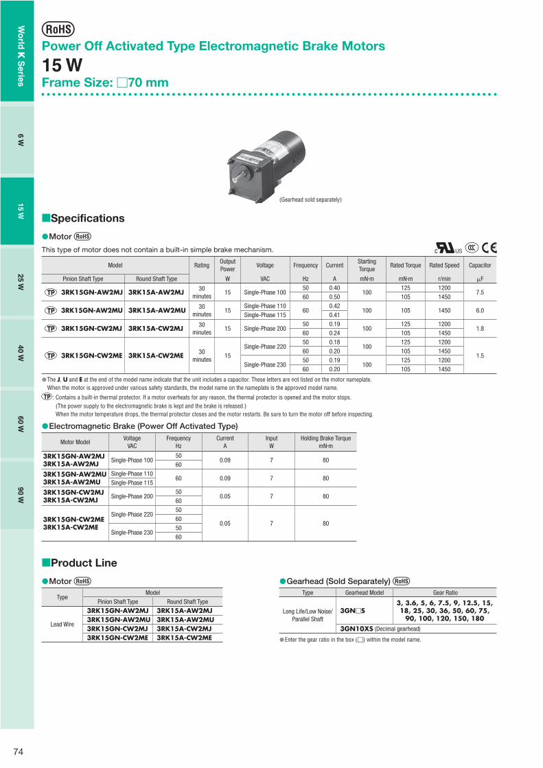
74
Power Off Activated Type Electromagnetic Brake Motors
15 WFrame Size: �70 mm
Specifications
Motor
This type of motor does not contain a built-in simple brake mechanism.
Model RatingOutputPower
Voltage Frequency CurrentStartingTorque
Rated Torque Rated Speed Capacitor
Pinion Shaft Type Round Shaft Type W VAC Hz A mN�m mN�m r/min �F
3RK15GN-AW2MJ 3RK15A-AW2MJ 30minutes
15 Single-Phase 10050 0.40
100125 1200
7.560 0.50 105 1450
3RK15GN-AW2MU 3RK15A-AW2MU 30minutes
15Single-Phase 110
600.42
100 105 1450 6.0Single-Phase 115 0.41
3RK15GN-CW2MJ 3RK15A-CW2MJ 30minutes
15 Single-Phase 20050 0.19
100125 1200
1.860 0.24 105 1450
3RK15GN-CW2ME 3RK15A-CW2ME 30minutes
15Single-Phase 220
50 0.18100
125 1200
1.560 0.20 105 1450
Single-Phase 23050 0.19
100125 1200
60 0.20 105 1450
The J, U and E at the end of the model name indicate that the unit includes a capacitor. These letters are not listed on the motor nameplate.When the motor is approved under various safety standards, the model name on the nameplate is the approved model name.
: Contains a built-in thermal protector. If a motor overheats for any reason, the thermal protector is opened and the motor stops.(The power supply to the electromagnetic brake is kept and the brake is released.) When the motor temperature drops, the thermal protector closes and the motor restarts. Be sure to turn the motor off before inspecting.
Electromagnetic Brake (Power Off Activated Type)
Motor ModelVoltage
VACFrequency
HzCurrent
AInput
WHolding Brake Torque
mN�m
3RK15GN-AW2MJ3RK15A-AW2MJ Single-Phase 100
500.09 7 80
60
3RK15GN-AW2MU3RK15A-AW2MU
Single-Phase 11060 0.09 7 80
Single-Phase 115
3RK15GN-CW2MJ3RK15A-CW2MJ Single-Phase 200
500.05 7 80
60
3RK15GN-CW2ME3RK15A-CW2ME
Single-Phase 22050
0.05 7 8060
Single-Phase 2305060
��
�
�
Product Line
Motor
TypeModel
Pinion Shaft Type Round Shaft Type
Lead Wire
3RK15GN-AW2MJ 3RK15A-AW2MJ3RK15GN-AW2MU 3RK15A-AW2MU3RK15GN-CW2MJ 3RK15A-CW2MJ3RK15GN-CW2ME 3RK15A-CW2ME
�� Gearhead (Sold Separately)
Type Gearhead Model Gear Ratio
Long Life/Low Noise/ Parallel Shaft
3GN�S3, 3.6, 5, 6, 7.5, 9, 12.5, 15, 18, 25, 30, 36, 50, 60, 75,
90, 100, 120, 150, 1803GN10XS (Decimal gearhead)
Enter the gear ratio in the box (�) within the model name.
�
�
(Gearhead sold separately)
Wo
rld K
Series
6 W15 W
25 W40 W
60 W90 W

75
Gearmotor – Torque TableGearheads and decimal gearheads are sold separately.Enter the gear ratio in the box (�) within the model name.A colored background indicates gear shaft rotation in the same direction as the motor shaft, while the others rotate in the opposite direction.The speed is calculated by dividing the motor's synchronous speed (50 Hz: 1500 r/min, 60 Hz: 1800 r/min) by the gear ratio.The actual speed is 2 - 20% less than the displayed value, depending on the size of the load.To reduce the speed beyond the gear ratio in the table, attach a decimal gearhead (gear ratio: 10) between the gearhead and the motor. In that case, the permissible torque is 5 N�m.
50 Hz Unit = N�m
ModelSpeedr/min
500 416 300 250 200 166 120 100 83 60 50 41 30 25 20 16 15 12.5 10 8.3
Motor/Gearhead
Gear Ratio 3 3.6 5 6 7.5 9 12.5 15 18 25 30 36 50 60 75 90 100 120 150 180
3RK15GN-AW2MJ3RK15GN-CW2MJ3RK15GN-CW2ME
3GN�S 0.30 0.36 0.51 0.61 0.76 0.91 1.3 1.5 1.8 2.3 2.7 3.3 4.1 5 5 5 5 5 5 5
60 Hz Unit = N�m
ModelSpeedr/min
600 500 360 300 240 200 144 120 100 72 60 50 36 30 24 20 18 15 12 10
Motor/Gearhead
Gear Ratio 3 3.6 5 6 7.5 9 12.5 15 18 25 30 36 50 60 75 90 100 120 150 180
3RK15GN-AW2MJ3RK15GN-AW2MU3RK15GN-CW2MJ3RK15GN-CW2ME
3GN�S 0.26 0.31 0.43 0.51 0.64 0.77 1.1 1.3 1.5 1.9 2.3 2.8 3.5 4.2 5 5 5 5 5 5
Permissible Overhung Load and Permissible Thrust LoadMotor (Round shaft type) ➜ Page 107Gearhead ➜ Page 107
Permissible Load Inertia J for Gearhead➜ Page 107
Starting and Braking Characteristics (Reference Values)
0.05 0.1 0.15 0.2
1
2
3
4
5
0
50
100
150
200
Over
run
[Rot
atio
ns]
Tim
e [m
s]
0
Load Inertia J [�10-4 kg�m2]
Single-Phase 50 Hz
Single-Phase 60 Hz
Braking Time
Starting Time
Overrun
����
�
�
�
�
�
�
�
Wo
rld K
Series
Ind
uctio
n M
oto
rsR
eversible M
oto
rsE
lec
trom
ag
ne
tic B
rak
e
Mo
tors
Torq
ue M
oto
rsR
igh
t-An
gle
Gearh
eads
Bra
ke
Pa
ck
SB5
0W
Accesso
ries2
-Po
le,
Hig
h-S
peed
Typ
e
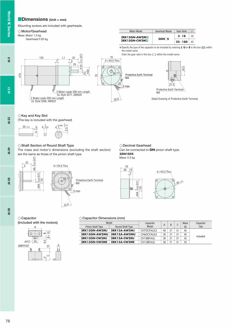
76
Dimensions (Unit = mm)
Mounting screws are included with gearheads.
Motor/GearheadMass: Motor 1.3 kg Gearhead 0.55 kg
�
�
2 Brake Leads 300 mm LengthUL Style 3266, AWG22
4�5.5 Thru
70
1207
L1 325
25
15 30
70
82�0.5
3 Motor Leads 300 mm LengthUL Style 3271, AWG20
70
10
�0.
015
( h7)
0
22.5˚
5 max.
Protective Earth TerminalM4
Key and Key Slot (The key is included with the gearhead)
25�0.2 4 0�0.040
2.5
0�0.
1
4�0.
03 0
4�0.03 0
�
Motor Model Gearhead Model Gear Ratio L1
3RK15GN-AW2M��
3RK15GN-CW2M��3GN�S
3�18 32
25�180 42
Specify the type of the capacitor to be included by entering J, U or E in the box (��) within the model name.Enter the gear ratio in the box (�) within the model name.
�
Shaft Section of Round Shaft TypeThe mass and motor's dimensions (excluding the shaft section) are the same as those of the pinion shaft type.
4�5.5 Thru232
82�0.5
�70
22.5˚
64
�0.
030
( h7)
0
6 �0.
012
( h7)
0
5 max.
Protective Earth TerminalM4
� Decimal GearheadCan be connected to GN pinion shaft type.3GN10XSMass: 0.3 kg
4330 13
2 4�5.5 Thru
82�0.5
64
�0.
030
( h7)
0 �70
�
Capacitor(Included with the motors)
4.3 20
A
CB�
10B4.
54
10 6AMP#187
� Capacitor Dimensions (mm)Model Capacitor
ModelA B C
Mass(g)
CapacitorCapPinion Shaft Type Round Shaft Type
3RK15GN-AW2MJ 3RK15A-AW2MJ CH75CFAUL2 48 21 31 45
Included3RK15GN-AW2MU 3RK15A-AW2MU CH60CFAUL2 38 21 31 403RK15GN-CW2MJ 3RK15A-CW2MJ CH18BFAUL 38 21 31 353RK15GN-CW2ME 3RK15A-CW2ME CH15BFAUL 38 21 31 35
�
16.5
21.5
Detail Drawing of Protective Earth Terminal
Protective Earth TerminalM4
Wo
rld K
Series
6 W15 W
25 W40 W
60 W90 W

77
Connection DiagramsThe direction of motor rotation is as viewed from the shaft end of the motor. CW represents the clockwise direction, while CCW represents the counterclockwise direction.Connection diagrams are also valid for the equivalent round shaft type.Specify the type of the capacitor to be included by entering J, U or E in the box (�) within the model name.
3RK15GN-AW2M�
3RK15GN-CW2M�SW1 ON
R0 C0
R0 C0
ON
SW2CCWCW
L
N
R0 C0
PE
CCW CW
SW1 operates both motor and electromagnetic brake action.The motor will rotate when SW1 is switched simultaneously to ON.When SW1 is switched simultaneously to OFF, the motor stops immediately with the electromagnetic brake and holds the load.
If you wish to release the brake while the motor is stopped, apply voltage between the two brake lead wires (orange).
Direction of RotationTo rotate the motor in a clockwise (CW) direction, turn SW2 to CW.To rotate the motor in a counterclockwise (CCW) direction, turn SW2 to CCW.
SwitchNo.
SW1 SW2
SpecificationsNote
Switched Simultaneously125 VAC 3 A minimum(Inductive Load)
250 VAC 1.5 A minimum(Inductive Load)
Single-Phase 100 VAC, 110/115 VAC Input
Single-Phase 200 VAC, 220/230 VAC Input
Red
White
Black
Orange
Orange
Capacitor
ElectromagneticBrake
Motor
PE: Protective EarthR0 and C0 indicate surge suppressor circuit. [R0�5�200 �, C0�0.1�0.2 �F, 200 WV (400 WV) ]EPCR1201-2 is available as an optional surge suppressor. ➜ Page 123
��
��
�
Wo
rld K
Series
Ind
uctio
n M
oto
rsR
eversible M
oto
rsE
lec
trom
ag
ne
tic B
rak
e
Mo
tors
Torq
ue M
oto
rsR
igh
t-An
gle
Gearh
eads
Bra
ke
Pa
ck
SB5
0W
Accesso
ries2
-Po
le,
Hig
h-S
peed
Typ
e

78
Power Off Activated Type Electromagnetic Brake Motors
25 WFrame Size: �80 mm
Specifications
Motor
This type of motor does not contain a built-in simple brake mechanism.
Model RatingOutputPower
Voltage Frequency CurrentStartingTorque
Rated Torque Rated Speed Capacitor
Pinion Shaft Type Round Shaft Type W VAC Hz A mN�m mN�m r/min �F
4RK25GN-AW2MJ 4RK25A-AW2MJ 30minutes
25 Single-Phase 10050 0.55 160 205 1200
1060 0.64 140 170 1450
4RK25GN-AW2MU 4RK25A-AW2MU 30minutes
25Single-Phase 110
60 0.54 140 170 1450 8.0Single-Phase 115
4RK25GN-CW2MJ 4RK25A-CW2MJ 30minutes
25Single-Phase 200
50 0.27 160 205 12002.560 0.34 140 170 1450
Single-Phase 220 50 0.27 160 205 1200
4RK25GN-CW2ME 4RK25A-CW2ME 30minutes
25Single-Phase 220 60 0.28 140 170 1450
2.0Single-Phase 230
50 0.25 160 205 120060 0.28 140 170 1450
4IK25GN-SW2M 4IK25A-SW2M Continuous 25Three-Phase 200
50 0.23 240 190 1300
�60 0.21 160 160 1550
Three-Phase 22060
0.20160 150 1600
Three-Phase 230 0.21
The J, U and E at the end of the model name indicate that the unit includes a capacitor. These letters are not listed on the motor nameplate.When the motor is approved under various safety standards, the model name on the nameplate is the approved model name.
: Contains a built-in thermal protector. If a motor overheats for any reason, the thermal protector is opened and the motor stops.(The power supply to the electromagnetic brake is kept and the brake is released.) When the motor temperature drops, the thermal protector closes and the motor restarts. Be sure to turn the motor off before inspecting.
Electromagnetic Brake (Power Off Activated Type)
Motor ModelVoltage
VACFrequency
HzCurrent
AInput
WHolding Brake Torque
mN�m
4RK25GN-AW2MJ4RK25A-AW2MJ Single-Phase 100
500.09 6 100
60
4RK25GN-AW2MU4RK25A-AW2MU
Single-Phase 11060 0.09 6 100
Single-Phase 115
4RK25GN-CW2MJ4RK25A-CW2MJ
Single-Phase 20050
0.05 7 10060Single-Phase 220 50
4RK25GN-CW2ME4RK25A-CW2ME
Single-Phase 220 600.05 7 100
Single-Phase 2305060
4IK25GN-SW2M4IK25A-SW2M
Single-Phase 20050
0.05 7 10060
Single-Phase 22060
Single-Phase 230
��
�
�
Product Line
MotorModel
Pinion Shaft Type Round Shaft Type
4RK25GN-AW2MJ 4RK25A-AW2MJ4RK25GN-AW2MU 4RK25A-AW2MU4RK25GN-CW2MJ 4RK25A-CW2MJ4RK25GN-CW2ME 4RK25A-CW2ME4IK25GN-SW2M 4IK25A-SW2M
�� Gearhead/Right-Angle Gearhead (Sold Separately)
Type Gearhead Model Gear Ratio
Long Life/Low Noise/ Parallel Shaft
4GN�S3, 3.6, 5, 6, 7.5, 9, 12.5, 15, 18, 25, 30, 36, 50, 60, 75,
90, 100, 120, 150, 1804GN10XS (Decimal gearhead)
Right-Angle/Hollow Shaft
4GN�RH3, 3.6, 5, 6, 7.5, 9, 12.5, 15, 18, 25, 30, 36, 50, 60, 75,
90, 100, 120, 150, 180
Right-Angle/Solid Shaft
4GN�RA3, 3.6, 5, 6, 7.5, 9, 12.5, 15, 18, 25, 30, 36, 50, 60, 75,
90, 100, 120, 150, 180
Enter the gear ratio in the box (�) within the model name.
�
�
Right-angle gearheads (hollow shaft or solid shaft) can be combined.Right-Angle Gearheads ➜ Page 108
(Gearhead sold separately)
Wo
rld K
Series
6 W15 W
25 W40 W
60 W90 W

79
Gearmotor – Torque TableGearheads and decimal gearheads are sold separately.Enter the gear ratio in the box (�) within the model name.A colored background indicates gear shaft rotation in the same direction as the motor shaft, while the others rotate in the opposite direction.The speed is calculated by dividing the motor's synchronous speed (50 Hz: 1500 r/min, 60 Hz: 1800 r/min) by the gear ratio. The actual speed is 2 - 20% less than the displayed value, depending on the size of the load.To reduce the speed beyond the gear ratio in the table, attach a decimal gearhead (gear ratio: 10) between the gearhead and the motor.In that case, the permissible torque is 8 N�m. When a gearhead of 1/25�1/36 is connected, the value for permissible torque is 6 N�m.
50 Hz Unit = N�m
ModelSpeedr/min
500 416 300 250 200 166 120 100 83 60 50 41 30 25 20 16 15 12.5 10 8.3
Motor/Gearhead
Gear Ratio 3 3.6 5 6 7.5 9 12.5 15 18 25 30 36 50 60 75 90 100 120 150 180
4RK25GN-AW2MJ4RK25GN-CW2MJ4RK25GN-CW2ME
4GN�S 0.50 0.60 0.83 1.0 1.2 1.5 2.1 2.5 3.0 3.7 4.5 5.4 6.8 8 8 8 8 8 8 8
4IK25GN-SW2M 4GN�S 0.46 0.55 0.77 0.92 1.2 1.4 1.9 2.3 2.8 3.5 4.2 5.0 6.3 7.5 8 8 8 8 8 8
60 Hz Unit = N�m
ModelSpeedr/min
600 500 360 300 240 200 144 120 100 72 60 50 36 30 24 20 18 15 12 10
Motor/Gearhead
Gear Ratio 3 3.6 5 6 7.5 9 12.5 15 18 25 30 36 50 60 75 90 100 120 150 180
4RK25GN-AW2MJ4RK25GN-AW2MU4RK25GN-CW2MJ4RK25GN-CW2ME
4GN�S 0.41 0.50 0.69 0.83 1.0 1.2 1.7 2.1 2.5 3.1 3.7 4.5 5.6 6.7 8 8 8 8 8 8
4IK25GN-SW2M(200 VAC)
4GN�S 0.39 0.47 0.65 0.78 0.97 1.2 1.6 1.9 2.3 2.9 3.5 4.2 5.3 6.3 7.9 8 8 8 8 8
4IK25GN-SW2M(220/230 VAC)
4GN�S 0.36 0.44 0.61 0.73 0.91 1.1 1.5 1.8 2.2 2.7 3.3 3.9 5.0 5.9 7.4 8 8 8 8 8
Permissible Overhung Load and Permissible Thrust LoadMotor (Round shaft type) ➜ Page 107Gearhead ➜ Page 107
Permissible Load Inertia J for Gearhead➜ Page 107
Starting and Braking Characteristics (Reference Values)
����
�
�
�
�
�
�
�
Single-Phase Motor
0 0.1 0.2 0.3 0.4
1
2
3
4
5
0
Over
run
[Rot
atio
ns]
Single-Phase 50 HzSingle-Phase 60 Hz
Load Inertia J [�10-4 kg�m2]
50
100
150
200
Tim
e [m
s]
Braking Time
Starting Time
Overrun
� Three-Phase Motor
0 0.1 0.2 0.3 0.4
1
2
3
4
5
0
Over
run
[Rot
atio
ns]
Load Inertia J [�10-4 kg�m2]
Three-Phase 50 HzThree-Phase 60 Hz
50
100
150
200
Tim
e [m
s]
Braking Time
Starting Time
Overrun
�
Wo
rld K
Series
Ind
uctio
n M
oto
rsR
eversible M
oto
rsE
lec
trom
ag
ne
tic B
rak
e
Mo
tors
Torq
ue M
oto
rsR
igh
t-An
gle
Gearh
eads
Bra
ke
Pa
ck
SB5
0W
Accesso
ries2
-Po
le,
Hig
h-S
peed
Typ
e
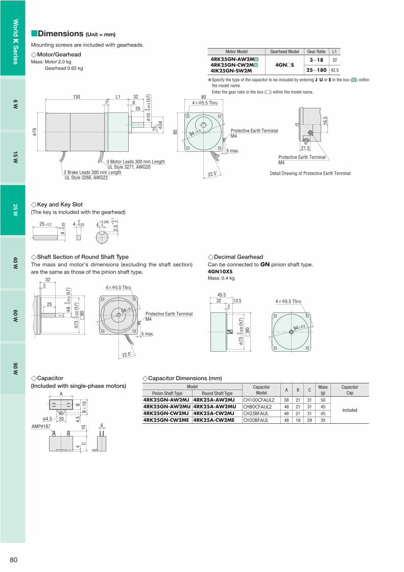
80
Dimensions (Unit = mm)
Mounting screws are included with gearheads.
Motor/GearheadMass: Motor 2.0 kg Gearhead 0.65 kg
�
� Motor Model Gearhead Model Gear Ratio L1
4RK25GN-AW2M��
4RK25GN-CW2M��
4IK25GN-SW2M4GN�S
3�18 32
25�180 42.5
Specify the type of the capacitor to be included by entering J, U or E in the box (��) within the model name.Enter the gear ratio in the box (�) within the model name.
�
79
1307
80
94�0.5
2 Brake Leads 300 mm LengthUL Style 3266, AWG22
3 Motor Leads 300 mm LengthUL Style 3271, AWG20
34
4�5.5 Thru
15
L1 326
25
80
10
�0.
015
( h7)
0
22.5˚
5 max.
Protective Earth TerminalM4
Shaft Section of Round Shaft TypeThe mass and motor's dimensions (excluding the shaft section) are the same as those of the pinion shaft type.
4�5.5 Thru232
94�0.525
7
�80
22.5˚
73
�0.
030
( h7)
0
8 �
0.01
5( h
7)0
5 max.
Protective Earth TerminalM4
� Decimal GearheadCan be connected to GN pinion shaft type.4GN10XSMass: 0.4 kg
45.532 13.5
2
�80
4�5.5 Thru
94�0.5
73
�0.
030
( h7)
0
�
Capacitor(Included with single-phase motors)
4.3 20
A
CB�
10B4.
54
10 6AMP#187
�
16.5
21.5
Detail Drawing of Protective Earth Terminal
Protective Earth TerminalM4
Key and Key Slot (The key is included with the gearhead)
25�0.2 4 0�0.040
2.5
0�0.
1
4�0.
03 0
4�0.03 0
�
Capacitor Dimensions (mm)Model Capacitor
ModelA B C
Mass(g)
CapacitorCapPinion Shaft Type Round Shaft Type
4RK25GN-AW2MJ 4RK25A-AW2MJ CH100CFAUL2 58 21 31 50
Included4RK25GN-AW2MU 4RK25A-AW2MU CH80CFAUL2 48 21 31 454RK25GN-CW2MJ 4RK25A-CW2MJ CH25BFAUL 48 21 31 454RK25GN-CW2ME 4RK25A-CW2ME CH20BFAUL 48 19 29 35
�
Wo
rld K
Series
6 W15 W
25 W40 W
60 W90 W

81
Connection DiagramsThe direction of motor rotation is as viewed from the shaft end of the motor. CW represents the clockwise direction, while CCW represents the counterclockwise direction.Connection diagrams are also valid for the equivalent round shaft type.Specify the type of the capacitor to be included by entering J, U or E in the box (�) within the model name.
4RK25GN-AW2M�
4RK25GN-CW2M�
4IK25GN-SW2M
Sing
le-P
hase
Mot
orTh
ree-
Phas
e M
otor
SW1 ON
R0 C0
R0 C0
ON
SW2CCWCW
L
N
R0 C0
PE
CCW CW
CW
L1(R)
L2(S)
L3(T)
SW1
R0 C0
R0 C0
R0 C0
PE
SW1 operates both motor and electromagnetic brake action.The motor will rotate when SW1 is switched simultaneously to ON.When SW1 is switched simultaneously to OFF, the motor stops immediately with the electromagnetic brake and holds the load.
If you wish to release the brake while the motor is stopped, apply voltage between the two brake lead wires (orange).
Direction of RotationTo rotate the motor in a clockwise (CW) direction, turn SW2 to CW.To rotate the motor in a counterclockwise (CCW) direction, turn SW2 to CCW.
SwitchNo.
SW1 SW2
SpecificationsNote
Switched Simultaneously125 VAC 3 A minimum(Inductive Load)
250 VAC 1.5 A minimum(Inductive Load)
Single-Phase 100 VAC, 110/115 VAC Input
Single-Phase 200 VAC, 220/230 VAC Input
SW1 operates both motor and electromagnetic brake action.The motor will rotate when SW1 is switched simultaneously to ON.When SW1 is switched simultaneously to OFF, the motor stops immediately with the electromagnetic brake and holds the load.
If you wish to release the brake while the motor is stopped, apply voltage between the two brake lead wires (orange).
Direction of RotationTo change the rotation direction, change any two connections between R, S and T.
SwitchNo.
SW1
Specifications
250 VAC 1.5 A minimum(Inductive Load)
Note
Switched Simultaneously
Red
White
Black
Orange
Orange
Capacitor
ElectromagneticBrake
Motor
White
Red
Black
Orange
OrangeElectromagnetic
Brake
Motor
PE: Protective EarthR0 and C0 indicate surge suppressor circuit. [R0�5�200 �, C0�0.1�0.2 �F, 200 WV (400 WV) ]EPCR1201-2 is available as an optional surge suppressor. ➜ Page 123
��
��
�
Wo
rld K
Series
Ind
uctio
n M
oto
rsR
eversible M
oto
rsE
lec
trom
ag
ne
tic B
rak
e
Mo
tors
Torq
ue M
oto
rsR
igh
t-An
gle
Gearh
eads
Bra
ke
Pa
ck
SB5
0W
Accesso
ries2
-Po
le,
Hig
h-S
peed
Typ
e

82
Power Off Activated Type Electromagnetic Brake Motors
40 WFrame Size: �90 mm
Specifications
Motor
This type of motor does not contain a built-in simple brake mechanism.
Model RatingOutputPower
Voltage Frequency CurrentStartingTorque
Rated Torque Rated Speed Capacitor
Pinion Shaft Type Round Shaft Type W VAC Hz A mN�m mN�m r/min �F
5RK40GN-AW2MJ 5RK40A-AW2MJ 30minutes
40 Single-Phase 10050 0.85 300 315 1250
1660 1.04 260 270 1450
5RK40GN-AW2MU 5RK40A-AW2MU 30minutes
40Single-Phase 110
60 0.81 260 270 1450 12Single-Phase 115
5RK40GN-CW2MJ 5RK40A-CW2MJ 30minutes
40Single-Phase 200
50 0.40 270 315 12504.060 0.51 260 260 1500
Single-Phase 220 50 0.40 270 315 1250
5RK40GN-CW2ME 5RK40A-CW2ME 30minutes
40Single-Phase 220 60 0.43 260 260 1500
3.5Single-Phase 230
50 0.38 270 315 125060 0.43 260 260 1500
5IK40GN-SW2M 5IK40A-SW2M Continuous 40Three-Phase 200
50 0.32 400 300 1300
�60 0.30 260 260 1550
Three-Phase 22060
0.30260 260 1600
Three-Phase 230 0.31
The J, U and E at the end of the model name indicate that the unit includes a capacitor. These letters are not listed on the motor nameplate.When the motor is approved under various safety standards, the model name on the nameplate is the approved model name.
: Contains a built-in thermal protector. If a motor overheats for any reason, the thermal protector is opened and the motor stops.(The power supply to the electromagnetic brake is kept and the brake is released.) When the motor temperature drops, the thermal protector closes and the motor restarts. Be sure to turn the motor off before inspecting.
Electromagnetic Brake (Power Off Activated Type)
Motor ModelVoltage
VACFrequency
HzCurrent
AInput
WHolding Brake Torque
mN�m
5RK40GN-AW2MJ5RK40A-AW2MJ Single-Phase 100
500.09 6 200
60
5RK40GN-AW2MU5RK40A-AW2MU
Single-Phase 11060 0.09 6 200
Single-Phase 115
5RK40GN-CW2MJ5RK40A-CW2MJ
Single-Phase 20050
0.05 7 20060Single-Phase 220 50
5RK40GN-CW2ME5RK40A-CW2ME
Single-Phase 220 600.05 7 200
Single-Phase 2305060
5IK40GN-SW2M5IK40A-SW2M
Single-Phase 20050
0.05 7 20060
Single-Phase 22060
Single-Phase 230
��
�
�
Product Line
MotorModel
Pinion Shaft Type Round Shaft Type
5RK40GN-AW2MJ 5RK40A-AW2MJ5RK40GN-AW2MU 5RK40A-AW2MU5RK40GN-CW2MJ 5RK40A-CW2MJ5RK40GN-CW2ME 5RK40A-CW2ME5IK40GN-SW2M 5IK40A-SW2M
�� Gearhead/Right-Angle Gearhead (Sold Separately)
Type Gearhead Model Gear Ratio
Long Life/Low Noise/ Parallel Shaft
5GN�S3, 3.6, 5, 6, 7.5, 9, 12.5, 15, 18, 25, 30, 36, 50, 60, 75,
90, 100, 120, 150, 1805GN10XS (Decimal gearhead)
Right-Angle/Hollow Shaft
5GN�RH3, 3.6, 5, 6, 7.5, 9, 12.5, 15, 18, 25, 30, 36, 50, 60, 75,
90, 100, 120, 150, 180
Right-Angle/Solid Shaft
5GN�RA3, 3.6, 5, 6, 7.5, 9, 12.5, 15, 18, 25, 30, 36, 50, 60, 75,
90, 100, 120, 150, 180
Enter the gear ratio in the box (�) within the model name.
�
�
Right-angle gearheads (hollow shaft or solid shaft) can be combined.Right-Angle Gearheads ➜ Page 108
(Gearhead sold separately)
Wo
rld K
Series
6 W15 W
25 W40 W
60 W90 W

83
Gearmotor – Torque TableGearheads and decimal gearheads are sold separately.Enter the gear ratio in the box (�) within the model name.A colored background indicates gear shaft rotation in the same direction as the motor shaft, while the others rotate in the opposite direction.The speed is calculated by dividing the motor's synchronous speed (50 Hz: 1500 r/min, 60 Hz: 1800 r/min) by the gear ratio. The actual speed is 2 - 20% less than the displayed value, depending on the size of the load.To reduce the speed beyond the gear ratio in the table, attach a decimal gearhead (gear ratio: 10) between the gearhead and the motor. In that case, the permissible torque is 10 N�m.
50 Hz Unit = N�m
ModelSpeedr/min
500 416 300 250 200 166 120 100 83 60 50 41 30 25 20 16 15 12.5 10 8.3
Motor/Gearhead
Gear Ratio 3 3.6 5 6 7.5 9 12.5 15 18 25 30 36 50 60 75 90 100 120 150 180
5RK40GN-AW2MJ5RK40GN-CW2MJ5RK40GN-CW2ME
5GN�S 0.77 0.92 1.3 1.5 1.9 2.3 3.2 3.8 4.6 5.7 6.9 8.3 10 10 10 10 10 10 10 10
5IK40GN-SW2M 5GN�S 0.73 0.87 1.2 1.5 1.8 2.2 3.0 3.6 4.4 5.5 6.6 7.9 9.9 10 10 10 10 10 10 10
60 Hz Unit = N�m
ModelSpeedr/min
600 500 360 300 240 200 144 120 100 72 60 50 36 30 24 20 18 15 12 10
Motor/Gearhead
Gear Ratio 3 3.6 5 6 7.5 9 12.5 15 18 25 30 36 50 60 75 90 100 120 150 180
5RK40GN-AW2MJ5RK40GN-AW2MU 5GN�S 0.66 0.79 1.1 1.3 1.6 2.0 2.7 3.3 3.9 4.9 5.9 7.1 8.9 10 10 10 10 10 10 10
5RK40GN-CW2MJ5RK40GN-CW2ME5IK40GN-SW2M
5GN�S 0.63 0.76 1.1 1.3 1.6 1.9 2.6 3.2 3.8 4.7 5.7 6.8 8.6 10 10 10 10 10 10 10
Permissible Overhung Load and Permissible Thrust LoadMotor (Round shaft type) ➜ Page 107Gearhead ➜ Page 107
Permissible Load Inertia J for Gearhead➜ Page 107
Starting and Braking Characteristics (Reference Values)
����
�
�
�
�
�
�
�
Single-Phase Motor
Load Inertia J [�10-4 kg�m2]
Braking Time
Starting Time
Overrun
1
2
3
4
5
00 0.25 0.5 0.75 1
Over
run
[Rot
atio
ns]
50
100
150
200
250
Tim
e [m
s]
Single-Phase 50 HzSingle-Phase 60 Hz
� Three-Phase Motor
1
2
3
4
5
0 0 0.25 0.5 0.75 1
Over
run
[Rot
atio
ns]
50
100
150
200
250
Tim
e [m
s]
Load Inertia J [�10-4 kg�m2]
Braking Time
Starting Time
Overrun
Three-Phase 50 HzThree-Phase 60 Hz
�
Wo
rld K
Series
Ind
uctio
n M
oto
rsR
eversible M
oto
rsE
lec
trom
ag
ne
tic B
rak
e
Mo
tors
Torq
ue M
oto
rsR
igh
t-An
gle
Gearh
eads
Bra
ke
Pa
ck
SB5
0W
Accesso
ries2
-Po
le,
Hig
h-S
peed
Typ
e

84
Dimensions (Unit = mm)
Mounting screws are included with gearheads.
Motor/GearheadMass: Motor 2.8 kg Gearhead 1.5 kg
�
�Motor Model Gearhead Model Gear Ratio L1
5RK40GN-AW2M��
5RK40GN-CW2M��
5IK40GN-SW2M5GN�S
3�18 42
25�180 60
Specify the type of the capacitor to be included by entering J, U or E in the box (��) within the model name.Enter the gear ratio in the box (�) within the model name.
�
904�6.5 Thru
89
1487.5
18
36
25
104�0.5
L1 324
2 Brake Leads 300 mm LengthUL Style 3266, AWG22
3 Motor Leads 300 mm LengthUL Style 3271, AWG20
90
12
�0.
018
( h7)
0
22.5˚
5 max.
Protective Earth TerminalM4
Key and Key Slot (The key is included with the gearhead)
25�0.2 4 0�0.040
2.5
0�0.
1
4�0.
03 0
4�0.03 0
�
Shaft Section of Round Shaft TypeThe mass and motor's dimensions (excluding the shaft section) are the same as those of the pinion shaft type.
237
30
9
4�6.5 Thru
104�0.5
�90
22.5˚
10
�0.
015
( h7)
0
83
�0.
035
( h7)
0
5 max.
Protective Earth TerminalM4
� Decimal GearheadCan be connected to GN pinion shaft type.5GN10XSMass: 0.6 kg
37 1855
2
�90
4�6.5 Thru
104�0.5
83
�0.
035
( h7)
0
�
Capacitor (Included with single-phase motors) Dimension No. � Dimension No. �
4.3 20
A
CB�
10B4.
54
10 6AMP#187
6
A
CB
720
10
AMP#187
4.3
4B �
15
R10
Capacitor Dimensions (mm)Model Capacitor
ModelA B C
Mass(g)
DimensionNo.
CapacitorCapPinion Shaft Type Round Shaft Type
5RK40GN-AW2MJ 5RK40A-AW2MJ CH160CFAUL2 58 23.5 37 75 �
Included5RK40GN-AW2MU 5RK40A-AW2MU CH120CFAUL2 58 22 35 60 �
5RK40GN-CW2MJ 5RK40A-CW2MJ CH40BFAUL 58 23.5 37 70 �
5RK40GN-CW2ME 5RK40A-CW2ME CH35BFAUL 58 22 35 55 �
�
�
16.5
21.5
Detail Drawing of Protective Earth Terminal
Protective Earth TerminalM4
Wo
rld K
Series
6 W15 W
25 W40 W
60 W90 W

85
Connection DiagramsThe direction of motor rotation is as viewed from the shaft end of the motor. CW represents the clockwise direction, while CCW represents the counterclockwise direction.Connection diagrams are also valid for the equivalent round shaft type.Specify the type of the capacitor to be included by entering J, U or E in the box (�) within the model name.
5RK40GN-AW2M�
5RK40GN-CW2M�
5IK40GN-SW2M
Sing
le-P
hase
Mot
orTh
ree-
Phas
e M
otor
SW1 ON
R0 C0
R0 C0
ON
SW2CCWCW
L
N
R0 C0
PE
CCW CW
CW
L1(R)
L2(S)
L3(T)
SW1
R0 C0
R0 C0
R0 C0
PE
SW1 operates both motor and electromagnetic brake action. The motor will rotate when SW1 is switched simultaneously to ON.When SW1 is switched simultaneously to OFF, the motor stops immediately with the electromagnetic brake and holds the load.
If you wish to release the brake while the motor is stopped, apply voltage between the two brake lead wires (orange).
Direction of RotationTo rotate the motor in a clockwise (CW) direction, turn SW2 to CW.To rotate the motor in a counterclockwise (CCW) direction, turn SW2 to CCW.
SwitchNo.
SW1 SW2
SpecificationsNote
Switched Simultaneously125 VAC 5 A minimum(Inductive Load)
250 VAC 5 A minimum(Inductive Load)
Single-Phase 100 VAC, 110/115 VAC Input
Single-Phase 200 VAC, 220/230 VAC Input
SW1 operates both motor and electromagnetic brake action.The motor will rotate when SW1 is switched simultaneously to ON.When SW1 is switched simultaneously to OFF, the motor stops immediately with the electromagnetic brake and holds the load.
If you wish to release the brake while the motor is stopped, apply voltage between the two brake lead wires (orange).
Direction of RotationTo change the rotation direction, change any two connections between R, S and T.
SwitchNo.
SW1
Specifications
250 VAC 5 A minimum(Inductive Load)
Note
Switched Simultaneously
Red
White
Black
Orange
Orange
Capacitor
ElectromagneticBrake
Motor
White
Red
Black
Orange
OrangeElectromagnetic
Brake
Motor
PE: Protective EarthR0 and C0 indicate surge suppressor circuit. [R0�5�200 �, C0�0.1�0.2 �F, 200 WV (400 WV) ]EPCR1201-2 is available as an optional surge suppressor. ➜ Page 123
��
��
�
Wo
rld K
Series
Ind
uctio
n M
oto
rsR
eversible M
oto
rsE
lec
trom
ag
ne
tic B
rak
e
Mo
tors
Torq
ue M
oto
rsR
igh
t-An
gle
Gearh
eads
Bra
ke
Pa
ck
SB5
0W
Accesso
ries2
-Po
le,
Hig
h-S
peed
Typ
e

86
Power Off Activated Type Electromagnetic Brake Motors
60 WFrame Size: �90 mm
Specifications
Motor
This type of motor does not contain a built-in simple brake mechanism.
Model RatingOutputPower
Voltage Frequency CurrentStartingTorque
Rated Torque Rated Speed Capacitor
Pinion Shaft Type Round Shaft Type W VAC Hz A mN�m mN�m r/min �F
5RK60GE-AW2MJ 5RK60A-AW2MJ 30minutes
60 Single-Phase 10050 1.30 470 490 1200
2560 1.50 380 405 1450
5RK60GE-AW2MU 5RK60A-AW2MU 30minutes
60Single-Phase 110
60 1.24 380 405 1450 20Single-Phase 115
5RK60GE-CW2MJ 5RK60A-CW2MJ 30minutes
60Single-Phase 200
50 0.61 450 490 12006.060 0.74 380 405 1450
Single-Phase 220 50 0.61 470 490 1200
5RK60GE-CW2ME 5RK60A-CW2ME 30minutes
60Single-Phase 220 60 0.61 380 405 1450
5.0Single-Phase 230
50 0.59 470 490 120060 0.61 380 405 1450
5IK60GE-SW2M 5IK60A-SW2M Continuous 60Three-Phase 200
50 0.50 600 450 1300
�60 0.43 500 380 1550
Three-Phase 22060
0.45500 380 1600
Three-Phase 230 0.46
The J, U and E at the end of the model name indicate that the unit includes a capacitor. These letters are not listed on the motor nameplate. When the motor is approved under various safety standards, the model name on the nameplate is the approved model name.
: Contains a built-in thermal protector. If a motor overheats for any reason, the thermal protector is opened and the motor stops.(The power supply to the electromagnetic brake is kept and the brake is released.) When the motor temperature drops, the thermal protector closes and the motor restarts. Be sure to turn the motor off before inspecting.
Electromagnetic Brake (Power Off Activated Type)
Motor ModelVoltage
VACFrequency
HzCurrent
AInput
WHolding Brake Torque
mN�m
5RK60GE-AW2MJ5RK60A-AW2MJ Single-Phase 100
500.13 10 500
60
5RK60GE-AW2MU5RK60A-AW2MU
Single-Phase 11060 0.13 10 500
Single-Phase 115
5RK60GE-CW2MJ5RK60A-CW2MJ
Single-Phase 20050
0.07 10 50060Single-Phase 220 50
5RK60GE-CW2ME5RK60A-CW2ME
Single-Phase 220 600.07 10 500
Single-Phase 2305060
5IK60GE-SW2M5IK60A-SW2M
Single-Phase 20050
0.07 10 50060
Single-Phase 22060
Single-Phase 230
��
�
�
Product Line
MotorModel
Pinion Shaft Type Round Shaft Type
5RK60GE-AW2MJ 5RK60A-AW2MJ5RK60GE-AW2MU 5RK60A-AW2MU5RK60GE-CW2MJ 5RK60A-CW2MJ5RK60GE-CW2ME 5RK60A-CW2ME5IK60GE-SW2M 5IK60A-SW2M
�� Gearhead/Right-Angle Gearhead (Sold Separately)
Type Gearhead Model Gear Ratio
Long Life/Parallel Shaft
5GE�S3, 3.6, 5, 6, 7.5, 9, 12.5, 15, 18, 25, 30, 36, 50, 60, 75,
90, 100, 120, 150, 1805GE10XS (Decimal gearhead)
Right-Angle/ Hollow Shaft
5GE�RH3, 3.6, 5, 6, 7.5, 9, 12.5, 15, 18, 25, 30, 36, 50, 60, 75,
90, 100, 120, 150, 180
Right-Angle/Solid Shaft
5GE�RA3, 3.6, 5, 6, 7.5, 9, 12.5, 15, 18, 25, 30, 36, 50, 60, 75,
90, 100, 120, 150, 180
Enter the gear ratio in the box (�) within the model name.
�
�
Right-angle gearheads (hollow shaft or solid shaft) can be combined.Right-Angle Gearheads ➜ Page 108
(Gearhead sold separately)
Wo
rld K
Series
6 W15 W
25 W40 W
60 W90 W

87
Gearmotor – Torque TableGearheads and decimal gearheads are sold separately.Enter the gear ratio in the box (�) within the model name.A colored background indicates gear shaft rotation in the same direction as the motor shaft, while the others rotate in the opposite direction.The speed is calculated by dividing the motor's synchronous speed (50 Hz: 1500 r/min, 60 Hz: 1800 r/min) by the gear ratio.The actual speed is 2 - 20% less than the displayed value, depending on the size of the load.To reduce the speed beyond the gear ratio in the table, attach a decimal gearhead (gear ratio: 10) between the gearhead and the motor. In that case, the permissible torque is 20 N�m.
50 Hz Unit = N�m
ModelSpeedr/min
500 416 300 250 200 166 120 100 83 60 50 41 30 25 20 16 15 12.5 10 8.3
Motor/Gearhead
Gear Ratio 3 3.6 5 6 7.5 9 12.5 15 18 25 30 36 50 60 75 90 100 120 150 180
5RK60GE-AW2MJ5RK60GE-CW2MJ5RK60GE-CW2ME
5GE�S 1.2 1.4 2.0 2.4 3.0 3.6 4.5 5.4 6.4 8.1 9.7 11.6 16.2 19.4 20 20 20 20 20 20
5IK60GE-SW2M 5GE�S 1.1 1.3 1.8 2.2 2.7 3.3 4.1 4.9 5.9 7.4 8.9 10.7 14.9 17.8 19.9 20 20 20 20 20
60 Hz Unit = N�m
ModelSpeedr/min
600 500 360 300 240 200 144 120 100 72 60 50 36 30 24 20 18 15 12 10
Motor/Gearhead
Gear Ratio 3 3.6 5 6 7.5 9 12.5 15 18 25 30 36 50 60 75 90 100 120 150 180
5RK60GE-AW2MJ5RK60GE-AW2MU5RK60GE-CW2MJ5RK60GE-CW2ME
5GE�S 0.98 1.2 1.6 2.0 2.5 3.0 3.7 4.4 5.3 6.7 8.0 9.6 13.4 16.0 17.9 20 20 20 20 20
5IK60GE-SW2M 5GE�S 0.92 1.1 1.5 1.8 2.3 2.8 3.5 4.2 5.0 6.3 7.5 9.0 12.5 15.0 16.8 20 20 20 20 20
Permissible Overhung Load and Permissible Thrust LoadMotor (Round shaft type) ➜ Page 107Gearhead ➜ Page 107
Permissible Load Inertia J for Gearhead➜ Page 107
Starting and Braking Characteristics (Reference Values)
����
�
�
�
�
�
�
�
Single-Phase Motor
Over
run
[Rot
atio
ns]
Tim
e [m
s]
0
1
2
3
4
5
0 0.25 0.5 0.75 1 1.25
150
100
50
Load Inertia J [�10-4 kg�m2]
Braking Time
Starting Time
Overrun
Single-Phase 50 HzSingle-Phase 60 Hz
� Three-Phase Motor
Over
run
[Rot
atio
ns]
0
1
2
3
4
5
0
150
100
50
Tim
e [m
s]
0.25 0.5 0.75 1 1.25Load Inertia J [�10-4 kg�m2]
Braking Time
Starting Time
Overrun
Three-Phase 50 HzThree-Phase 60 Hz
�
Wo
rld K
Series
Ind
uctio
n M
oto
rsR
eversible M
oto
rsE
lec
trom
ag
ne
tic B
rak
e
Mo
tors
Torq
ue M
oto
rsR
igh
t-An
gle
Gearh
eads
Bra
ke
Pa
ck
SB5
0W
Accesso
ries2
-Po
le,
Hig
h-S
peed
Typ
e
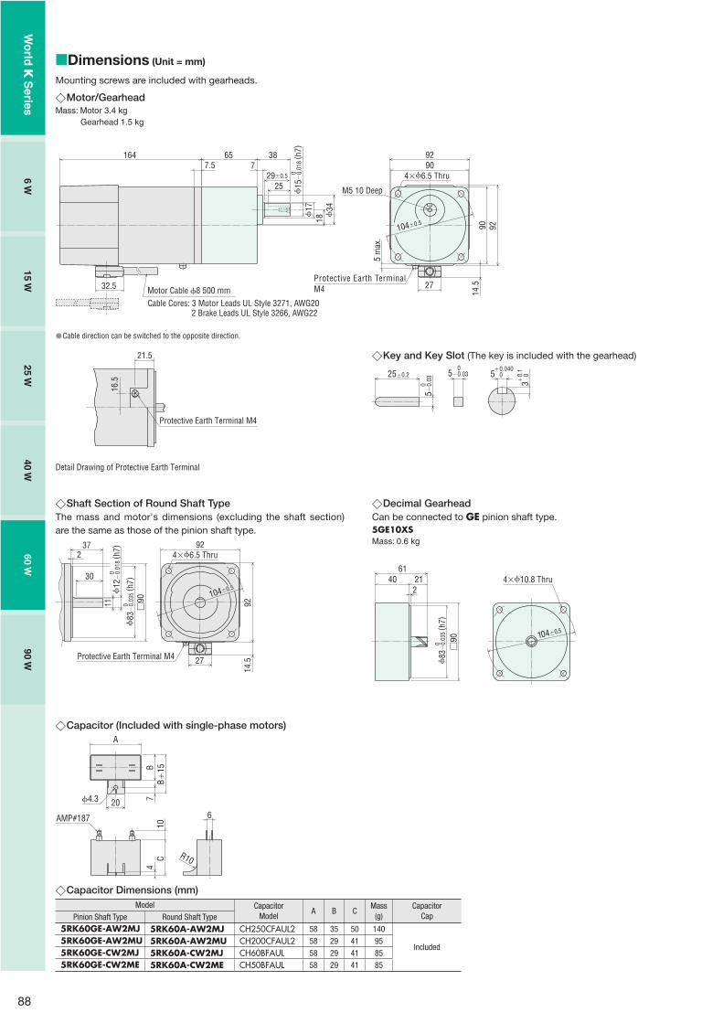
88
Dimensions (Unit = mm)
Mounting screws are included with gearheads.
Motor/GearheadMass: Motor 3.4 kg Gearhead 1.5 kg
�
�
Motor Cable 8 500 mm
4�6.5 Thru
M5 10 Deep
18
1647.5
32.5
34
25
65 387
92
14.5
92
27
90
17
29�0.5
90104�0.5
Cable Cores: 3 Motor Leads UL Style 3271, AWG202 Brake Leads UL Style 3266, AWG22
15
�0.
018
( h7)
0
5 m
ax.
Protective Earth TerminalM4
Cable direction can be switched to the opposite direction.�
21.5
16.5
Detail Drawing of Protective Earth Terminal
Protective Earth Terminal M4
Key and Key Slot (The key is included with the gearhead)
25�0.2 5 0�0.040
3 0�0.
1
5�0.
03 0
5�0.03 0
�
Decimal GearheadCan be connected to GE pinion shaft type.5GE10XSMass: 0.6 kg
6140 21
24�10.8 Thru
104�0.5
83
�0.
035
( h7)
0
�90
�Shaft Section of Round Shaft TypeThe mass and motor's dimensions (excluding the shaft section) are the same as those of the pinion shaft type.
104�0.5
30
372
11 �90
4�6.5 Thru
9214
.5
92
27Protective Earth Terminal M4
83
�0.
035
( h7)
0
12�
0.01
8( h
7)0
�
Capacitor (Included with single-phase motors)
6
A
CB
720
10
AMP#187
4.3
4B �
15
R10
Capacitor Dimensions (mm)Model Capacitor
ModelA B C
Mass(g)
CapacitorCapPinion Shaft Type Round Shaft Type
5RK60GE-AW2MJ 5RK60A-AW2MJ CH250CFAUL2 58 35 50 140
Included5RK60GE-AW2MU 5RK60A-AW2MU CH200CFAUL2 58 29 41 955RK60GE-CW2MJ 5RK60A-CW2MJ CH60BFAUL 58 29 41 855RK60GE-CW2ME 5RK60A-CW2ME CH50BFAUL 58 29 41 85
�
�
Wo
rld K
Series
6 W15 W
25 W40 W
60 W90 W

89
Connection DiagramsThe direction of motor rotation is as viewed from the shaft end of the motor. CW represents the clockwise direction, while CCW represents the counterclockwise direction.Connection diagrams are also valid for the equivalent round shaft type.Specify the type of the capacitor to be included by entering J, U or E in the box (�) within the model name.
5RK60GE-AW2M�
5RK60GE-CW2M�
5IK60GE-SW2M
Sing
le-P
hase
Mot
orTh
ree-
Phas
e M
otor
SW1 ON
R0 C0
R0 C0
ON
SW2CCWCW
L
N
R0 C0
PE
CCW CW
CW
L1(R)
L2(S)
L3(T)
SW1
R0 C0
R0 C0
R0 C0
PE
SW1 operates both motor and electromagnetic brake action.The motor will rotate when SW1 is switched simultaneously to ON.When SW1 is switched simultaneously to OFF, the motor stops immediately with the electromagnetic brake and holds the load.
If you wish to release the brake while the motor is stopped, apply voltage between the two brake lead wires (orange).
Direction of RotationTo rotate the motor in a clockwise (CW) direction, turn SW2 to CW.To rotate the motor in a counterclockwise (CCW) direction, turn SW2 to CCW.
SwitchNo.
SW1 SW2
SpecificationsNote
Switched Simultaneously125 VAC 5 A minimum(Inductive Load)
250 VAC 5 A minimum(Inductive Load)
Single-Phase 100 VAC, 110/115 VAC Input
Single-Phase 200 VAC, 220/230 VAC Input
SW1 operates both motor and electromagnetic brake action.The motor will rotate when SW1 is switched simultaneously to ON.When SW1 is switched simultaneously to OFF, the motor stops immediately with the electromagnetic brake and holds the load.
If you wish to release the brake while the motor is stopped, apply voltage between the two brake lead wires (orange).
Direction of RotationTo change the rotation direction, change any two connections between R, S and T.
SwitchNo.
SW1
Specifications
250 VAC 5 A minimum(Inductive Load)
Note
Switched Simultaneously
Red
White
Black
Orange
Orange
Capacitor
ElectromagneticBrake
Motor
White
Red
Black
Orange
OrangeElectromagnetic
Brake
Motor
PE: Protective EarthR0 and C0 indicate surge suppressor circuit. [R0�5�200 �, C0�0.1�0.2 �F, 200 WV (400 WV) ]EPCR1201-2 is available as an optional surge suppressor. ➜ Page 123
��
��
�
Wo
rld K
Series
Ind
uctio
n M
oto
rsR
eversible M
oto
rsE
lec
trom
ag
ne
tic B
rak
e
Mo
tors
Torq
ue M
oto
rsR
igh
t-An
gle
Gearh
eads
Bra
ke
Pa
ck
SB5
0W
Accesso
ries2
-Po
le,
Hig
h-S
peed
Typ
e

90
Power Off Activated Type Electromagnetic Brake Motors
90 WFrame Size: �90 mm
Specifications
Motor
This type of motor does not contain a built-in simple brake mechanism.
Model RatingOutputPower
Voltage Frequency CurrentStartingTorque
Rated Torque Rated Speed Capacitor
Pinion Shaft Type Round Shaft Type W VAC Hz A mN�m mN�m r/min �F
5RK90GE-AW2MJ 5RK90A-AW2MJ 30minutes
90 Single-Phase 10050 1.78 630 700 1250
3560 2.10 590 585 1500
5RK90GE-AW2MU 5RK90A-AW2MU 30minutes
90Single-Phase 110
60 1.81 590 585 1500 30Single-Phase 115
5RK90GE-CW2MJ 5RK90A-CW2MJ 30minutes
90Single-Phase 200
50 0.88 600 730 12008.060 1.08 590 605 1450
Single-Phase 220 50 0.83 600 730 1200
5RK90GE-CW2ME 5RK90A-CW2ME 30minutes
90Single-Phase 220 60 0.96 590 605 1450
7.0Single-Phase 230
50 0.82 600 730 120060 0.96 590 605 1450
5IK90GE-SW2M 5IK90A-SW2M Continuous 90Three-Phase 200
50 0.64 850 680 1300
�60 0.59 700 570 1550
Three-Phase 22060
0.60700 570 1600
Three-Phase 230 0.61
The J, U and E at the end of the model name indicate that the unit includes a capacitor. These letters are not listed on the motor nameplate.When the motor is approved under various safety standards, the model name on the nameplate is the approved model name.
: Contains a built-in thermal protector. If a motor overheats for any reason, the thermal protector is opened and the motor stops.(The power supply to the electromagnetic brake is kept and the brake is released.) When the motor temperature drops, the thermal protector closes and the motor restarts. Be sure to turn the motor off before inspecting.
Electromagnetic Brake (Power Off Activated Type)
Motor ModelVoltage
VACFrequency
HzCurrent
AInput
WHolding Brake Torque
mN�m
5RK90GE-AW2MJ5RK90A-AW2MJ Single-Phase 100
500.13 10 500
60
5RK90GE-AW2MU5RK90A-AW2MU
Single-Phase 11060 0.13 10 500
Single-Phase 115
5RK90GE-CW2MJ5RK90A-CW2MJ
Single-Phase 20050
0.07 10 50060Single-Phase 220 50
5RK90GE-CW2ME5RK90A-CW2ME
Single-Phase 220 600.07 10 500
Single-Phase 2305060
5IK90GE-SW2M5IK90A-SW2M
Single-Phase 20050
0.07 10 50060
Single-Phase 22060
Single-Phase 230
��
�
�
Right-angle gearheads (hollow shaft or solid shaft) can be combined.Right-Angle Gearheads ➜ Page 108
(Gearhead sold separately)
Wo
rld K
Series
6 W15 W
25 W40 W
60 W90 W

91
Product Line
MotorModel
Pinion Shaft Type Round Shaft Type
5RK90GE-AW2MJ 5RK90A-AW2MJ5RK90GE-AW2MU 5RK90A-AW2MU5RK90GE-CW2MJ 5RK90A-CW2MJ5RK90GE-CW2ME 5RK90A-CW2ME5IK90GE-SW2M 5IK90A-SW2M
�� Gearhead/Right-Angle Gearhead (Sold Separately)
Type Gearhead Model Gear Ratio
Long Life/ Parallel Shaft
5GE�S3, 3.6, 5, 6, 7.5, 9, 12.5, 15, 18, 25, 30, 36, 50, 60, 75,
90, 100, 120, 150, 1805GE10XS (Decimal gearhead)
Right-Angle/Hollow Shaft
5GE�RH3, 3.6, 5, 6, 7.5, 9, 12.5, 15, 18, 25, 30, 36, 50, 60, 75,
90, 100, 120, 150, 180
Right-Angle/Solid Shaft
5GE�RA3, 3.6, 5, 6, 7.5, 9, 12.5, 15, 18, 25, 30, 36, 50, 60, 75,
90, 100, 120, 150, 180
Enter the gear ratio in the box (�) within the model name.
�
�
Gearmotor – Torque TableGearheads and decimal gearheads are sold separately.Enter the gear ratio in the box (�) within the model name.A colored background indicates gear shaft rotation in the same direction as the motor shaft, while the others rotate in the opposite direction.The speed is calculated by dividing the motor's synchronous speed (50 Hz: 1500 r/min, 60 Hz: 1800 r/min) by the gear ratio.The actual speed is 2 - 20% less than the displayed value, depending on the size of the load.To reduce the speed beyond the gear ratio in the table, attach a decimal gearhead (gear ratio: 10) between the gearhead and the motor. In that case, the permissible torque is 20 N�m.
50 Hz Unit = N�m
ModelSpeedr/min
500 416 300 250 200 166 120 100 83 60 50 41 30 25 20 16 15 12.5 10 8.3
Motor/Gearhead
Gear Ratio 3 3.6 5 6 7.5 9 12.5 15 18 25 30 36 50 60 75 90 100 120 150 180
5RK90GE-AW2MJ 5GE�S 1.7 2.0 2.8 3.4 4.3 5.1 6.4 7.7 9.2 11.6 13.9 16.6 20 20 20 20 20 20 20 20
5RK90GE-CW2MJ5RK90GE-CW2ME 5GE�S 1.8 2.1 3.0 3.5 4.4 5.3 6.7 8.0 9.6 12.0 14.5 17.3 20 20 20 20 20 20 20 20
5IK90GE-SW2M 5GE�S 1.7 2.0 2.8 3.3 4.1 5.0 6.2 7.4 8.9 11.2 13.5 16.2 20 20 20 20 20 20 20 20
60 Hz Unit = N�m
ModelSpeedr/min
600 500 360 300 240 200 144 120 100 72 60 50 36 30 24 20 18 15 12 10
Motor/Gearhead
Gear Ratio 3 3.6 5 6 7.5 9 12.5 15 18 25 30 36 50 60 75 90 100 120 150 180
5RK90GE-AW2MJ5RK90GE-AW2MU 5GE�S 1.4 1.7 2.4 2.8 3.6 4.3 5.3 6.4 7.7 9.7 11.6 13.9 19.3 20 20 20 20 20 20 20
5RK90GE-CW2MJ5RK90GE-CW2ME 5GE�S 1.5 1.8 2.5 2.9 3.7 4.4 5.5 6.6 7.9 10.0 12.0 14.4 20 20 20 20 20 20 20 20
5IK90GE-SW2M 5GE�S 1.4 1.7 2.3 2.8 3.5 4.2 5.2 6.2 7.5 9.4 11.3 13.5 18.8 20 20 20 20 20 20 20
����
�
�
�
�
Permissible Overhung Load and Permissible Thrust LoadMotor (Round shaft type) ➜ Page 107Gearhead ➜ Page 107
Permissible Load Inertia J for Gearhead➜ Page 107
�
�
Wo
rld K
Series
Ind
uctio
n M
oto
rsR
eversible M
oto
rsE
lec
trom
ag
ne
tic B
rak
e
Mo
tors
Torq
ue M
oto
rsR
igh
t-An
gle
Gearh
eads
Bra
ke
Pa
ck
SB5
0W
Accesso
ries2
-Po
le,
Hig
h-S
peed
Typ
e

92
Starting and Braking Characteristics (Reference Values)�
Dimensions (Unit = mm)
Mounting screws are included with gearheads.
Motor/GearheadMass: Motor 3.9 kg Gearhead 1.5 kg
4�6.5 Thru
18
1797.5
32.5
34
65 387
14.5
92
27
90
90 92104�0.5
Motor Cable 8 500 mmCable Cores: 3 Motor Leads UL Style 3271, AWG20
2 Brake Leads UL Style 3266, AWG22
15
�0.
018
( h7)
0
5 m
ax.
M5 10 Deep25
17
29�0.5
Protective Earth TerminalM4
Cable direction can be switched to the opposite direction.
�
�
�
21.5
16.5
Detail Drawing of Protective Earth Terminal
Protective Earth Terminal M4
Key and Key Slot (The key is included with the gearhead)
25�0.2 5 0�0.040
3 0�0.
1
5�0.
03 0
5�0.03 0
�
Single-Phase Motor
Over
run
[Rot
atio
ns]
0
1
2
3
4
5
0
150
100
50
Single-Phase 50 HzSingle-Phase 60 Hz
Tim
e [m
s]
0.25 0.5 0.75 1 1.25Load Inertia J [�10-4 kg�m2]
Braking Time
Starting Time
Overrun
� Three-Phase Motor
Over
run
[Rot
atio
ns]
0
1
2
3
4
5
0
150
100
50
Tim
e [m
s]
0.25 0.5 0.75 1 1.25Load Inertia J [�10-4 kg�m2]
Braking Time
Starting Time
Overrun
Three-Phase 50 HzThree-Phase 60 Hz
�
Wo
rld K
Series
6 W15 W
25 W40 W
60 W90 W

93
Connection DiagramsThe direction of motor rotation is as viewed from the shaft end of the motor. CW represents the clockwise direction, while CCW represents the counterclockwise direction.Connection diagrams are also valid for the equivalent round shaft type.Specify the type of the capacitor to be included by entering J, U or E in the box (�) within the model name.
5RK90GE-AW2M�
5RK90GE-CW2M�
5IK90GE-SW2M
Sing
le-P
hase
Mot
orTh
ree-
Phas
e M
otor
SW1 ON
R0 C0
R0 C0
ON
SW2CCWCW
L
N
R0 C0
PE
CCW CW
CW
L1(R)
L2(S)
L3(T)
SW1
R0 C0
R0 C0
R0 C0
PE
SW1 operates both motor and electromagnetic brake action.The motor will rotate when SW1 is switched simultaneously to ON.When SW1 is switched simultaneously to OFF, the motor stops immediately with the electromagnetic brake and holds the load.
If you wish to release the brake while the motor is stopped, apply voltage between the two brake lead wires (orange).
Direction of RotationTo rotate the motor in a clockwise (CW) direction, turn SW2 to CW.To rotate the motor in a counterclockwise (CCW) direction, turn SW2 to CCW.
SwitchNo.
SW1 SW2
SpecificationsNote
Switched Simultaneously125 VAC 5 A minimum(Inductive Load)
250 VAC 5 A minimum(Inductive Load)
Single-Phase 100 VAC, 110/115 VAC Input
Single-Phase 200 VAC, 220/230 VAC Input
SW1 operates both motor and electromagnetic brake action.The motor will rotate when SW1 is switched simultaneously to ON.When SW1 is switched simultaneously to OFF, the motor stops immediately with the electromagnetic brake and holds the load.
If you wish to release the brake while the motor is stopped, apply voltage between the two brake lead wires (orange).
Direction of RotationTo change the rotation direction, change any two connections between R, S and T.
SwitchNo.
SW1
Specifications
250 VAC 5 A minimum(Inductive Load)
Note
Switched Simultaneously
Red
White
Black
Orange
Orange
Capacitor
ElectromagneticBrake
Motor
White
Red
Black
Orange
OrangeElectromagnetic
Brake
Motor
PE: Protective EarthR0 and C0 indicate surge suppressor circuit. [R0�5�200 �, C0�0.1�0.2 �F, 200 WV (400 WV) ]EPCR1201-2 is available as an optional surge suppressor. ➜ Page 123
��
��
�
Decimal GearheadCan be connected to GE pinion shaft type.5GE10XSMass: 0.6 kg
6140 21
24�10.8 Thru
104�0.5
83
�0.
035
( h7)
0
�90
�Shaft Section of Round Shaft TypeThe mass and motor's dimensions (excluding the shaft section) are the same as those of the pinion shaft type.
104�0.5
30
372
11 �90
4�6.5 Thru
9214
.5
92
27Protective Earth Terminal M4
83
�0.
035
( h7)
0
12�
0.01
8( h
7)0
�
Capacitor (Included with single-phase motors)
6
A
CB
720
10
AMP#187
4.3
4B �
15
R10
�
Capacitor Dimensions (mm)Model Capacitor
ModelA B C
Mass(g)
CapacitorCapPinion Shaft Type Round Shaft Type
5RK90GE-AW2MJ 5RK90A-AW2MJ CH350CFAUL2 58 41 58 180
Included5RK90GE-AW2MU 5RK90A-AW2MU CH300CFAUL2 58 35 50 1405RK90GE-CW2MJ 5RK90A-CW2MJ CH80BFAUL 58 35 50 1305RK90GE-CW2ME 5RK90A-CW2ME CH70BFAUL 58 35 50 130
�
Wo
rld K
Series
Ind
uctio
n M
oto
rsR
eversible M
oto
rsE
lec
trom
ag
ne
tic B
rak
e
Mo
tors
Torq
ue M
oto
rsR
igh
t-An
gle
Gearh
eads
Bra
ke
Pa
ck
SB5
0W
Accesso
ries2
-Po
le,
Hig
h-S
peed
Typ
e

94
Torque Motors
Features
The Speed Can Vary Widely, Depending on the Sloping Characteristics.
Torque motors have a high starting torque and sloping characteristics, a l lowing easy speed control simply by changing the voltage of the power supply. (The motor torque changes approximately proportion to the square of the voltage.)
�� Suitable for Winding Applications
In an appl icat ion where an object is released continuously at a constant speed and wound up with constant tension, the torque must be doubled and the speed must be halved if the diameter of the winding spool is doubled.
Use as a BrakeBy using the motor in the braking region of the speed–torque characteristics, it can serve as a brake.Constant tension operation can be achieved by applying a DC voltage.
�
�
RoHS-Compliant
N4 N3 N2 N1
V1>V2>V3>V4V1
V2
V3
V4
Torq
ue
Speed
Load
Constant Tension Wind Up
Brake
Safety Standards and CE MarkingStandards Certification Body Standards File No. CE Marking
UL 1004UL 2111
UL E64197
Low Voltage Directives
CSA C22.2 No.100CSA C22.2 No.77
EN 60950-1EN 60034-1EN 60034-5IEC 60664-1
Conform to EN/IEC Standards
GB 12350 CQC 2005010401150784 (3 W�20 W)
When the motor is approved under various safety standards, the model name on the nameplate is the approved model name.
�
�W
orld
K S
eries

95
System Configuration
�Example of System Configuration
Mounting Brackets (Accessories)(➜ Page 121)
Gearheads (Sold separately)
Flexible Couplings (Accessories)(➜ Page 123)
Capacitor Cap✽ (Included)Insulating cap for capacitor terminal section.
Capacitor (Included)
Torque Motor
Motor (Pinion Shaft)4TK10GN-CW2E
(Body)
Mounting BracketLong Life/Low NoiseGN-S Gearhead
4GN25S SOL4M5 MCL301012
Flexible Coupling
AC Power Supply
✽Capacitor cap is included.
(Sold separately): Required under this system.: Selectable according to necessity. Oriental Motor provides.
The system configuration shown above is an example. Other configurations are available. Decimal gearheads are also available.
�
�
Wo
rld K
Series
Ind
uctio
n M
oto
rsR
eversible M
oto
rsE
lec
trom
ag
ne
tic B
rak
e
Mo
tors
Torq
ue M
oto
rsR
igh
t-An
gle
Gearh
eads
Bra
ke
Pa
ck
SB5
0W
Accesso
ries2
-Po
le,
Hig
h-S
peed
Typ
e

96
Product Number Code
Motor
5 T K 20 GN - CW 2 Eq uw ie r t y
��
Gearhead
5 GN 50 Sq w e r
�
Product Line
Motor
Output PowerModel
Pinion Shaft Type Round Shaft Type
3 W
2TK3GN-AW2J 2TK3A-AW2J2TK3GN-AW2U 2TK3A-AW2U2TK3GN-CW2J 2TK3A-CW2J2TK3GN-CW2E 2TK3A-CW2E
6 W
3TK6GN-AW2J 3TK6A-AW2J3TK6GN-AW2U 3TK6A-AW2U3TK6GN-CW2J 3TK6A-CW2J3TK6GN-CW2E 3TK6A-CW2E
10 W
4TK10GN-AW2J 4TK10A-AW2J4TK10GN-AW2U 4TK10A-AW2U4TK10GN-CW2J 4TK10A-CW2J4TK10GN-CW2E 4TK10A-CW2E
20 W
5TK20GN-AW2J 5TK20A-AW2J5TK20GN-AW2U 5TK20A-AW2U5TK20GN-CW2J 5TK20A-CW2J5TK20GN-CW2E 5TK20A-CW2E
�� Gearhead (Sold Separately)
Applicable Motor Output Power
(Pinion Shaft Type)Gearhead Model Gear Ratio
3 W2GN�S
3, 3.6, 5, 6, 7.5, 9, 12.5, 15, 18, 25, 30, 36, 50, 60, 75,
90, 100, 120, 150, 1802GN10XS (Decimal gearhead)
6 W3GN�S
3, 3.6, 5, 6, 7.5, 9, 12.5, 15, 18, 25, 30, 36, 50, 60, 75,
90, 100, 120, 150, 1803GN10XS (Decimal gearhead)
10 W4GN�S
3, 3.6, 5, 6, 7.5, 9, 12.5, 15, 18, 25, 30, 36, 50, 60, 75,
90, 100, 120, 150, 1804GN10XS (Decimal gearhead)
20 W5GN�S
3, 3.6, 5, 6, 7.5, 9, 12.5, 15, 18, 25, 30, 36, 50, 60, 75,
90, 100, 120, 150, 1805GN10XS (Decimal gearhead)
Enter the gear ratio in the box (�) within the model name.
�
�
� Motor Frame Size 2: 60 mm 3: 70 mm 4: 80 mm 5: 90 mm
� Motor Type T: Torque Motors
� Series K: K Series
� Output Power (W) (Example) 20: 20 W
� Motor Shaft TypeGN: GN Type Pinion ShaftA: Round Shaft
� Power Supply VoltageAW: Single-Phase 100 VAC, 110/115 VACCW: Single-Phase 200 VAC, 220/230 VAC
2: RoHS-Compliant
Included CapacitorJ: For Single-Phase 100 VAC, 200 VAC U: For Single-Phase 110/115 VACE: For Single-Phase 220/230 VAC
The J, U and E at the end of the model name indicate that the unit includes a capacitor. These letters are not listed on the motor nameplate.When the motor is approved under various safety standards, the model name on the nameplate is the approved model name.(Example) Model: 5TK20GN-CW2E
➜ Motor nameplate and product approved under various safety standards: 5TK20GN-CW2
�
� Gearhead Frame Size 2: 60 mm 3: 70 mm 4: 80 mm 5: 90 mm
� Type of Pinion GN: GN Type Pinion
� Gear Ratio(Example) 50: Gear Ratio of 1:5010X denotes the decimal gearhead of gear ratio 1:10
� GN Type Pinion S: Long Life/Low Noise GN-S Gearhead, RoHS-Compliant
Note:A right-angle gearhead cannot be combined.
Wo
rld K
Series

97
Specifications
3 W, 6 W, 10 W
ModelRating at LockedRotor
Voltage
VAC
Frequency
Hz
Starting Torque
mN�m
Max.OutputPower
W
Speed atMax. Output
Powerr/min
Torque atMax. Output
PowermN�m
Current atMax. Output
PowerA
Input Power at Max.
Output PowerW
Capacitor
�FPinion Shaft Type Round Shaft Type
2TK3GN-AW2J 2TK3A-AW2J5 minutes 100
50 70 3 750 39 0.42 40
7.060 70 3.5 900 38 0.48 45
Continuous 5050 18 0.8 750 10 0.21 1060 20 1 900 11 0.30 14
2TK3GN-AW2U 2TK3A-AW2U5 minutes
11060 70 3.5 900 38
0.42 456.0115 0.45 50
Continuous 60 60 25 1.2 900 13 0.26 15
2TK3GN-CW2J 2TK3A-CW2J5 minutes 200
50 70 3 750 39 0.210 40
1.860 70 3.5 900 38 0.230 45
Continuous 10050 18 0.8 750 10 0.105 1060 20 1 900 11 0.150 15
2TK3GN-CW2E 2TK3A-CW2E5 minutes
22050 70 3 750 39
0.220 45
1.5
230 0.240 50220
60 70 3.5 900 380.215 45
230 0.230 50
Continuous 11550 18 0.8 750 10 0.095 1060 25 1.2 900 13 0.130 14
3TK6GN-AW2J 3TK6A-AW2J5 minutes 100
50 140 6 750 78 0.64 60
1160 140 7.5 900 82 0.63 60
Continuous 5050 40 1.6 750 21 0.31 1560 45 2 900 23 0.45 20
3TK6GN-AW2U 3TK6A-AW2U5 minutes
11060 150 8 900 87
0.60 659.0115 0.65 70
Continuous 60 60 55 2.6 900 28 0.37 20
3TK6GN-CW2J 3TK6A-CW2J5 minutes 200
50 140 6 750 78 0.340 60
3.060 140 7.5 900 82 0.340 65
Continuous 10050 40 1.6 750 21 0.165 1560 45 2 900 23 0.245 25
3TK6GN-CW2E 3TK6A-CW2E5 minutes
22050 140 6 750 78
0.390 70
2.5
230 0.440 80220
60 150 8 900 870.320 70
230 0.350 75
Continuous 11550 45 1.8 750 24 0.145 1560 55 2.6 900 28 0.210 24
4TK10GN-AW2J 4TK10A-AW2J5 minutes 100
50 220 10 750 130 0.76 70
1460 210 12 900 130 0.88 85
Continuous 5050 60 2.3 750 30 0.40 2060 65 2.8 900 30 0.54 25
4TK10GN-AW2U 4TK10A-AW2U5 minutes
11060 210 12 900 130
0.74 8011115 0.76 85
Continuous 60 60 70 3.3 900 35 0.45 25
4TK10GN-CW2J 4TK10A-CW2J5 minutes 200
50 220 10 750 130 0.38 70
3.560 210 12 900 130 0.43 85
Continuous 10050 60 2.3 750 30 0.19 1960 65 2.8 900 30 0.27 25
4TK10GN-CW2E 4TK10A-CW2E5 minutes
22050 220 10 750 130
0.41 80
3.0
230 0.45 90220
60 210 12 900 1300.39 80
230 0.40 80
Continuous 11550 65 2.8 750 35 0.18 2060 70 3.3 900 35 0.24 25
The J, U and E at the end of the model name indicate that the unit includes a capacitor. These letters are not listed on the motor nameplate.When the motor is approved under various safety standards, the model name on the nameplate is the approved model name.
: Contains a built-in thermal protector. If a motor overheats for any reason, the thermal protector is opened and the motor stops.When the motor temperature drops, the thermal protector closes and the motor restarts. Be sure to turn the motor off before inspecting.
�
�
�
Wo
rld K
Series
Ind
uctio
n M
oto
rsR
eversible M
oto
rsE
lec
trom
ag
ne
tic B
rak
e
Mo
tors
Torq
ue M
oto
rsR
igh
t-An
gle
Gearh
eads
Bra
ke
Pa
ck
SB5
0W
Accesso
ries2
-Po
le,
Hig
h-S
peed
Typ
e

98
20 W
ModelRating at LockedRotor
Voltage
VAC
Frequency
Hz
Starting Torque
mN�m
Max.OutputPower
W
Speed atMax. Output
Powerr/min
Torque atMax. Output
PowermN�m
Current atMax. Output
PowerA
Input Power at Max.
Output PowerW
Capacitor
�FPinion Shaft Type Round Shaft Type
5TK20GN-AW2J 5TK20A-AW2J5 minutes 100
50 350 20 750 260 1.00 90
1860 300 20 900 220 1.18 115
Continuous 5050 80 4 750 50 0.50 2560 85 4 900 45 0.69 34
5TK20GN-AW2U 5TK20A-AW2U5 minutes
11060 350 23 900 250
1.00 11014115 1.02 115
Continuous 60 60 100 5.5 900 60 0.58 34
5TK20GN-CW2J 5TK20A-CW2J5 minutes 200
50 350 20 750 260 0.57 105
4.560 300 20 900 220 0.55 105
Continuous 10050 80 4 750 50 0.24 2460 85 4 900 45 0.31 30
5TK20GN-CW2E 5TK20A-CW2E5 minutes
22050 350 20 750 260
0.63 120
4.0
230 0.68 130220
60 350 20 900 2200.53 115
230 0.54 120
Continuous 11550 85 4.5 750 60 0.26 2960 100 5.5 900 60 0.30 34
The J, U and E at the end of the model name indicate that the unit includes a capacitor. These letters are not listed on the motor nameplate.When the motor is approved under various safety standards, the model name on the nameplate is the approved model name.
: Contains a built-in thermal protector. If a motor overheats for any reason, the thermal protector is opened and the motor stops.When the motor temperature drops, the thermal protector closes and the motor restarts. Be sure to turn the motor off before inspecting.
General Specifications
3 W, 6 W, 10 W, 20 WItem Specifications
Insulation Resistance 100 M� or more when 500 VDC megger is applied between the windings and the frame after rated motor operation under normal ambient temperature and humidity.
Dielectric StrengthSufficient to withstand 1.5 kV at 50 Hz or 60 Hz applied between the windings and the frame for 1 minute after rated motor operation under normal ambient temperature and humidity.
Temperature RiseTemperature rise of windings are 80˚C or less measured by the resistance change method after rated motor operation under normal ambient temperature and humidity, with connecting a gearhead or equivalent heat radiation plate✽.
Insulation Class Class B (130˚C)
Overheat ProtectionBuilt-in thermal protector (automatic return type)3W type open: 130˚C�5˚C, close: 90˚C�15˚COther type open: 130˚C�5˚C, close: 82˚C�15˚C
Ambient TemperatureSingle-Phase 50 VAC, Single-Phase 100 VAC, Single-Phase 200 VAC:�10˚C��50˚C (nonfreezing)Single-Phase 60 VAC, Single-Phase 110 VAC, Single-Phase 115 VAC, Single-Phase 220 VAC, Single-Phase 230 VAC:�10˚C��40˚C (nonfreezing)
Ambient Humidity 85% or less (noncondensing)Degree of Protection IP20
Heat radiation plate (Material: Aluminum)
Motor Type Size (mm) Thickness (mm)3 W Type 115�115
56 W Type 125�12510 W Type 135�13520 W Type 165�165
�
�
��
✽
Wo
rld K
Series

99
How to Read Speed – Torque Characteristics
The motor torque changes approximately proportion to the square of the voltage. When the voltage supplied to the motor is changed, speed – torque curves with a sloping characteristics (torque is highest at zero speed and decreases steadily with increasing speed) shifts to that of the corresponding voltage.When the voltage is changed to 100 VAC, 80 VAC and 60 VAC while the load torque is T0, the motor rotates at the speeds N1, N2
and N3 respectively. Thus, the speed can be changed easily by varying the voltage.
When choosing a torque motor, first determine the required torque and speed. Then select a motor using the speed – torque characteristics curves to determine whether the motor should be operated under continuous duty or limited duty. When used under locked rotor conditions, only the torque factor is considered.The temperature rise of the motor may cause a problem during continuous operation. In this case, choose a motor with an output power large enough for continuous operation and adjust the voltage to control the torque and speed.
�
0 1000500 180015000
0.55
0.40
0.45
0.50
0.30
0.35
0.10
0.15
0.05
0.20
0.25
Torq
ue [N
�m]
Speed [r/min]
T0
N3 N2 N1
5TK20A-AW2J 50 HzVoltage 40 VAC�100 VAC
100 V
80 V
40 V
50 V
60 V
Voltage Control of Torque MotorsThe method most commonly used to control voltage is by phase control using a triac. As shown in Fig. 1, by changing the phase angle "�"at which the triac switches, the input voltage is controlled as represented by the phase angle areas of the graph.
PhaseAngle
ConductanceAngle
Volta
ge
0 2
�+ �
32
2
Fig. 1 Phase Control
�
Gearmotor – Torque TableDue to the sloping characteristics, torque motors can be operated over a wide speed range, from locked rotor condition to the maximumspeed. The permissible torque when a gearhead and a decimal gearhead are directly connected can be calculated according to the following formula, using the speed and torque determined from the speed – torque characteristics.
Speed of gearhead output shaft NG�Motor speed�1/gearhead gear ratioOutput torque of gearhead TG�Motor torque�Gearhead gear ratio�Gearhead efficiency
The output torque of the gearhead must be lower than the maximum permissible torque.
�
50 100 150 200
10
Gear Ratio
Maximum Permissible Torque of Gearheads
0
20
5GN�S4GN�S
3GN�S
2GN�S
Torq
ue [N
�m]
Gearhead Model Gearhead Gear Ratio Gearhead Efficiency
2GN�S3GN�S4GN�S5GN�S
3�18 81%
25�36 73%
50�180 66%
Gearheads and decimal gearheads are sold separately.Enter the gear ratio in the box (�) within the model name.
��
Wo
rld K
Series
Ind
uctio
n M
oto
rsR
eversible M
oto
rsE
lec
trom
ag
ne
tic B
rak
e
Mo
tors
Torq
ue M
oto
rsR
igh
t-An
gle
Gearh
eads
Bra
ke
Pa
ck
SB5
0W
Accesso
ries2
-Po
le,
Hig
h-S
peed
Typ
e

100
Speed – Torque Characteristics (Reference Values)�
2TK3GN-CW2J, 2TK3A-CW2J
0 1000500 180015000
0.12
0.10
0.08
0.06
0.02
0.04
Torq
ue [N
�m]
Speed [r/min]
50 Hz60 Hz
200 V
100 V
60 V
160 V
120 V
80 V
2TK3GN-CW2E, 2TK3A-CW2E
0 1000500 180015000
0.12
0.10
0.08
0.06
0.02
0.04
Torq
ue [N
�m]
Speed [r/min]
50 Hz60 Hz
220 V
220 V
230 V
230 V
140 V
115 V
80 V
60 V
3TK6GN-AW2J, 3TK6A-AW2J
0 1000500 180015000
0.20
0.16
0.18
0.12
0.14
0.04
0.06
0.02
0.08
0.10
Torq
ue [N
�m]
Speed [r/min]
50 Hz60 Hz
100 V
80 V
60 V
50 V
40 V
3TK6GN-AW2U, 3TK6A-AW2U
0 1000500 180015000
0.20
0.16
0.18
0.12
0.14
0.04
0.06
0.02
0.08
0.10
Torq
ue [N
�m]
Speed [r/min]
60 Hz
110 V
115 V
80 V
60 V
40 V
2TK3GN-AW2J, 2TK3A-AW2J
0 1000500 180015000
0.10
0.08
0.06
0.02
0.04Torq
ue [N
�m]
Speed [r/min]
50 Hz60 Hz
100 V
80 V
60 V
50 V
40 V
2TK3GN-AW2U, 2TK3A-AW2U
0 1000500 180015000
0.12
0.10
0.08
0.06
0.02
0.04
Torq
ue [N
�m]
Speed [r/min]
60 Hz
110 V
80 V
60 V
115 V
40 V
Wo
rld K
Series

101
3TK6GN-CW2J, 3TK6A-CW2J
0 1000500 180015000
0.22
0.16
0.18
0.20
0.12
0.14
0.04
0.06
0.02
0.08
0.10
Torq
ue [N
�m]
Speed [r/min]
50 Hz60 Hz
200 V
120 V
100 V
80 V
160 V
60 V
3TK6GN-CW2E, 3TK6A-CW2E
0 1000500 180015000
0.22
0.16
0.18
0.20
0.12
0.14
0.04
0.06
0.02
0.08
0.10
Torq
ue [N
�m]
Speed [r/min]
50 Hz60 Hz
220 V
230 V
230 V
115 V
80 V
220 V
60 V
140 V
4TK10GN-AW2J, 4TK10A-AW2J
0 1000500 180015000
0.35
0.30
0.25
0.10
0.05
0.20
0.15Torq
ue [N
�m]
Speed [r/min]
50 Hz60 Hz
100 V
80 V
60 V
50 V
40 V
4TK10GN-AW2U, 4TK10A-AW2U
0 1000500 180015000
0.35
0.30
0.25
0.10
0.05
0.20
0.15Torq
ue [N
�m]
Speed [r/min]
60 Hz115 V
80 V
60 V
110 V
40 V
4TK10GN-CW2J, 4TK10A-CW2J
0 1000500 180015000
0.35
0.30
0.25
0.10
0.05
0.20
0.15Torq
ue [N
�m]
Speed [r/min]
50 Hz60 Hz
200 V
160 V
120 V
100 V
80 V
60 V
4TK10GN-CW2E, 4TK10A-CW2E
0 1000500 180015000
0.35
0.30
0.25
0.10
0.05
0.20
0.15Torq
ue [N
�m]
Speed [r/min]
50 Hz60 Hz
230 V
220 V
220 V
230 V
140 V
115 V
60 V
80 V
Wo
rld K
Series
Ind
uctio
n M
oto
rsR
eversible M
oto
rsE
lec
trom
ag
ne
tic B
rak
e
Mo
tors
Torq
ue M
oto
rsR
igh
t-An
gle
Gearh
eads
Bra
ke
Pa
ck
SB5
0W
Accesso
ries2
-Po
le,
Hig
h-S
peed
Typ
e
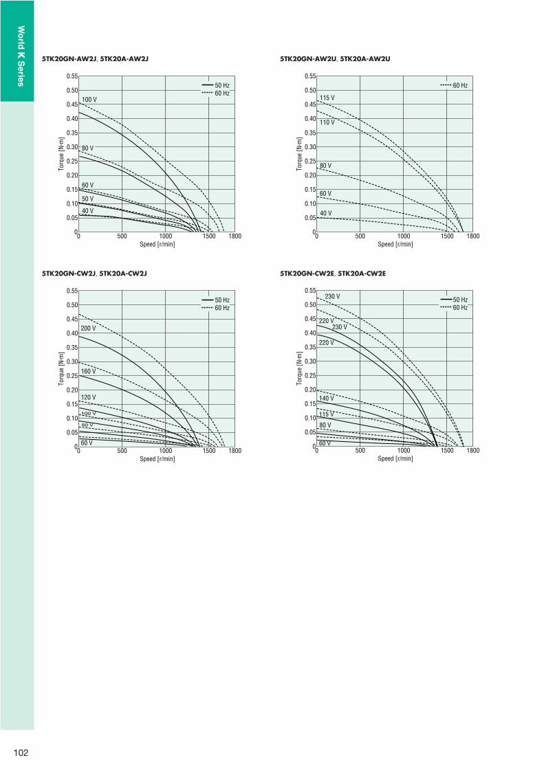
102
5TK20GN-AW2J, 5TK20A-AW2J
0 1000500 180015000
0.55
0.40
0.45
0.50
0.30
0.35
0.10
0.15
0.05
0.20
0.25
Torq
ue [N
�m]
Speed [r/min]
50 Hz60 Hz
100 V
80 V
40 V
50 V
60 V
5TK20GN-AW2U, 5TK20A-AW2U
0 1000500 180015000
0.55
0.40
0.45
0.50
0.30
0.35
0.10
0.15
0.05
0.20
0.25
Torq
ue [N
�m]
Speed [r/min]
60 Hz
115 V
110 V
40 V
80 V
60 V
5TK20GN-CW2J, 5TK20A-CW2J
0 1000500 180015000
0.55
0.40
0.45
0.50
0.30
0.35
0.10
0.15
0.05
0.20
0.25
Torq
ue [N
�m]
Speed [r/min]
50 Hz60 Hz
200 V
120 V
100 V
80 V
160 V
60 V
5TK20GN-CW2E, 5TK20A-CW2E
0 1000500 180015000
0.55
0.40
0.45
0.50
0.30
0.35
0.10
0.15
0.05
0.20
0.25
Torq
ue [N
�m]
Speed [r/min]
50 Hz60 Hz
230 V
230 V
140 V
115 V
80 V
220 V
60 V
220 V
Wo
rld K
Series

103
Shaft Section of Round Shaft Type2TK3A-AW2��
2TK3A-CW2��
The mass and motor's dimensions (excluding the shaft section) are the same as those of the pinion shaft type.
224
22.5˚
4�4.5 Thru
70�0.5
�60
54
�0.
030
( h7)
0
6 �
0.01
2( h
7)0
5 max.
Protective Earth TerminalM4
�
Dimensions (Unit = mm)
Mounting screws are included with gearheads.
3 W
Motor/GearheadMass: Motor 0.7 kg Gearhead 0.4 kg
4�4.5 Thru
Motor Leads 300 mm LengthUL Style 3271, AWG20
75 L1 325
10
12
24
60
60
7
7 70�0.5
22.5˚
60
8�
0.01
5( h
7)0
5 max.
Protective Earth TerminalM4
�
��
Decimal GearheadCan be connected to 2TK3GN type.2GN10XSMass: 0.2 kg
38.526 12.5
2 4�4.5 Thru
70�0.5
�60
54
�0.
030
( h7)
0
�
Motor Model Gearhead Model Gear Ratio L1
2TK3GN-AW2��
2TK3GN-CW2��2GN�S
3�18 30
25�180 40
Specify the type of the capacitor to be included by entering J, U or E in the box (��) within the model name.Enter the gear ratio in the box (�) within the model name.
�
15.5
21.5
Detail Drawing of Protective Earth Terminal
Protective Earth TerminalM4
6 W
Motor/GearheadMass: Motor 1.1 kg Gearhead 0.55 kg
69
807
L1 325
25
15 30
82�0.5
Motor Leads 300 mm LengthUL Style 3271, AWG20
70
70
4�5.5 Thru
22.5˚
10
�0.
015
( h7)
0
5 max.
Protective Earth TerminalM4
��
Motor Model Gearhead Model Gear Ratio L1
3TK6GN-AW2��
3TK6GN-CW2��3GN�S
3�18 32
25�180 42
Specify the type of the capacitor to be included by entering J, U or E in the box (��) within the model name.Enter the gear ratio in the box (�) within the model name.
�
16.5
21.5
Detail Drawing of Protective Earth Terminal
Protective Earth TerminalM4
Key and Key Slot (The key is included with the gearhead)
25�0.2 4 0�0.040
2.5
0�0.
1
4�0.
03 0
4�0.03 0
�
Wo
rld K
Series
Ind
uctio
n M
oto
rsR
eversible M
oto
rsE
lec
trom
ag
ne
tic B
rak
e
Mo
tors
Torq
ue M
oto
rsR
igh
t-An
gle
Gearh
eads
Bra
ke
Pa
ck
SB5
0W
Accesso
ries2
-Po
le,
Hig
h-S
peed
Typ
e

104
Shaft Section of Round Shaft Type3TK6A-AW2��
3TK6A-CW2��
The mass and motor's dimensions (excluding the shaft section) are the same as those of the pinion shaft type.
4�5.5 Thru232
82�0.5
�70
22.5˚
64
�0.
030
( h7)
0
6 �0.
012
( h7)
0
5 max.
Protective Earth TerminalM4
� Decimal GearheadCan be connected to 3TK6GN type.3GN10XSMass: 0.3 kg
4330 13
2 4�5.5 Thru
82�0.5
64
�0.
030
( h7)
0 �70
�
10 W
Motor/GearheadMass: Motor 1.5 kg Gearhead 0.65 kg
4�5.5 Thru
79
L185 326
94�0.5
7
25
34
15
80
Motor Leads 300 mm LengthUL Style 3271, AWG20
80
22.5˚
10
�0.
015
( h7)
0
5 max.
Protective Earth TerminalM4
��
Shaft Section of Round Shaft Type4TK10A-AW2��
4TK10A-CW2��
The mass and motor's dimensions (excluding the shaft section) are the same as those of the pinion shaft type.
4�5.5 Thru232
94�0.525
7
�80
22.5˚
73
�0.
030
( h7)
0
8 �
0.01
5( h
7)0
5 max.
Protective Earth TerminalM4
� Decimal GearheadCan be connected to 4TK10GN type.4GN10XSMass: 0.4 kg
45.532 13.5
2
�80
4�5.5 Thru
94�0.5
73
�0.
030
( h7)
0
�
Motor Model Gearhead Model Gear Ratio L1
4TK10GN-AW2��
4TK10GN-CW2��4GN�S
3�18 32
25�180 42.5
Specify the type of the capacitor to be included by entering J, U or E in the box (��) within the model name.Enter the gear ratio in the box (�) within the model name.
�
Key and Key Slot (The key is included with the gearhead)
25�0.2 4 0�0.040
2.5
0�0.
1
4�0.
03 0
4�0.03 0
�16
.5
21.5
Detail Drawing of Protective Earth Terminal
Protective Earth TerminalM4
Wo
rld K
Series

105
20 W
Motor/GearheadMass: Motor 2.5 kg Gearhead 1.5 kg
4�6.5 Thru
89
105 L14
327.5
18 36
25
90
Motor Leads 300 mm LengthUL Style 3271, AWG20
104�0.5
90
22.5
12
�0.
018
( h7)
0
5 max.
Protective Earth TerminalM4
��
Key and Key Slot (The key is included with the gearhead)
25�0.2 4 0�0.040
2.5
0�0.
1
4�0.
03 0
4�0.03 0
�
Shaft Section of Round Shaft Type5TK20A-AW2��
5TK20A-CW2��
The mass and motor's dimensions (excluding the shaft section) are the same as those of the pinion shaft type.
237
30
9
4�6.5 Thru
104�0.5
�90
22.5˚
10
�0.
015
( h7)
0
83
�0.
035
( h7)
0
5 max.
Protective Earth TerminalM4
� Decimal GearheadCan be connected to 5TK20GN type.5GN10XSMass: 0.6 kg
37 1855
2
�90
4�6.5 Thru
104�0.5
83
�0.
035
( h7)
0
�
16.5
21.5
Detail Drawing of Protective Earth Terminal
Protective Earth TerminalM4
Motor Model Gearhead Model Gear Ratio L1
5TK20GN-AW2��
5TK20GN-CW2��5GN�S
3�18 42
25�180 60
Specify the type of the capacitor to be included by entering J, U or E in the box (��) within the model name.Enter the gear ratio in the box (�) within the model name.
�
Wo
rld K
Series
Ind
uctio
n M
oto
rsR
eversible M
oto
rsE
lec
trom
ag
ne
tic B
rak
e
Mo
tors
Torq
ue M
oto
rsR
igh
t-An
gle
Gearh
eads
Bra
ke
Pa
ck
SB5
0W
Accesso
ries2
-Po
le,
Hig
h-S
peed
Typ
e

106
�Capacitor (Included with the motors)
Dimension No. � Dimension No. �
4.3 20
A
CB�
10B4.
54
10 6AMP#187
6
A
CB
720
10
AMP#187
4.3
4B�
15
R10
Capacitor Dimensions (mm)Model Capacitor
ModelA B C
Mass(g)
DimensionNo.
CapacitorCapPinion Shaft Type Round Shaft Type
2TK3GN-AW2J 2TK3A-AW2J CH70CFAUL2 48 19 29 36 �
Included
2TK3GN-AW2U 2TK3A-AW2U CH60CFAUL2 38 21 31 40 �
2TK3GN-CW2J 2TK3A-CW2J CH18BFAUL 38 21 31 35 �
2TK3GN-CW2E 2TK3A-CW2E CH15BFAUL 38 21 31 35 �
3TK6GN-AW2J 3TK6A-AW2J CH110CFAUL2 58 21 31 50 �
3TK6GN-AW2U 3TK6A-AW2U CH90CFAUL2 48 22.5 31.5 45 �
3TK6GN-CW2J 3TK6A-CW2J CH30BFAUL 58 21 31 50 �
3TK6GN-CW2E 3TK6A-CW2E CH25BFAUL 48 21 31 45 �
4TK10GN-AW2J 4TK10A-AW2J CH140CFAUL2 58 22 35 61 �
4TK10GN-AW2U 4TK10A-AW2U CH110CFAUL2 58 21 31 50 �
4TK10GN-CW2J 4TK10A-CW2J CH35BFAUL 58 22 35 55 �
4TK10GN-CW2E 4TK10A-CW2E CH30BFAUL 58 21 31 50 �
5TK20GN-AW2J 5TK20A-AW2J CH180CFAUL2 58 29 41 95 �
5TK20GN-AW2U 5TK20A-AW2U CH140CFAUL2 58 22 35 61 �
5TK20GN-CW2J 5TK20A-CW2J CH45BFAUL 58 23.5 37 73 �
5TK20GN-CW2E 5TK20A-CW2E CH40BFAUL 58 23.5 37 70 �
Connection DiagramsThe direction of motor rotation is as viewed from the shaft end of the motor. CW represents the clockwise direction, while CCW represents the counterclockwise direction.Connection diagrams are also valid for the equivalent round shaft type.Specify the type of the capacitor to be included by entering J, U or E in the box (�) within the model name.
2TK3GN-AW2�, 2TK3GN-CW2�, 3TK6GN-AW2�, 3TK6GN-CW2�
4TK10GN-AW2�, 4TK10GN-CW2�, 5TK20GN-AW2�, 5TK20GN-CW2�
Clockwise Counterclockwise
Capacitor
Black
RedL
N
White
Black
Red
White
MotorPE
CW
L
N
MotorPE
Capacitor
CCW
PE: Protective Earth
�
�
��
��
Wo
rld K
Series

107
Common Specifications
Permissible Overhung Load and Permissible Thrust Load of Motor
Permissible Overhung LoadMotor Permissible Overhung Load N
Motor Frame Size� (mm)
Output Shaft Diameter (mm)
Distance from Shaft End10 mm 20 mm
42 5 40 �
60 6 50 11070 6 40 60
808 90 140
10 110 120
9010 140 20012 240 270
Permissible Thrust LoadAvoid thrust loads as much as possible. If thrust load is unavoidable, keep it to half or less of the motor mass.
Permissible Overhung Load and Permissible Thrust Load of Gearheads
Model Gear RatioMaximum Permissible Torque
N�mPermissible Overhung Load N Permissible Thrust Load
N10 mm from Shaft End 20 mm from Shaft End
0GN�K 3�180 1.0 20 � 15
2GN�S3�18
3.050 80
3025�180 120 180
3GN�S3�18
5.080 120
4025�180 150 250
4GN�S3�18
8.0100 150
5025�180 200 300
5GN�S3�18
10250 350
10025�180 300 450
5GE�S3�9
20400 500
15012.5�18 450 600
25�180 500 700
Permissible Load Inertia for Gearhead JWhen a high load inertia (J) is connected to a gearhead, high torque is exerted instantaneously on the gearhead when starting up in frequent, discontinuous operations (or when stopped by an electromagnetic brake, or when stopped instantaneously by a brake pack).Excessive impact loads can cause the gearhead or motor damage.The table below gives values for permissible load inertia on the motor shaft. Use the motor and gearhead within these parameters. The permissible inertial load value shown for three-phase motors is the value when reversing after a stop.The permissible load inertia (J) on the gearhead output shaft is calculated with the following equation.The life of the gearhead when operating at the permissible inertial load with instantaneous stops of the motors with electromagnetic brakes, brake packs or speed control motors is at least 2 million cycles.
Permissible Load Inertia for Gearhead Output Shaft
Gear ratio 1/3�1/50 JG�JM�i2 JG : Permissible load inertia for gearhead output shaft J (�10-4 kg�m2)Gear ratio 1/60 or higher JG�JM�2500 JM : Pemissible load inertia at the motor shaft J (�10-4 kg�m2)
i : Gear ratio (Example: i�3 means the gear ratio of 1/3)
Permissible Load Inertia at the Motor Shaft
No. of Phase Motor Frame Size Output PowerPermissible Load Inertia at the Motor Shaft
J (�10-4kg�m2)
Single-Phase
� 42 mm 1 W, 3 W 0.016� 60 mm 3 W✽ , 6 W 0.062� 70 mm 6 W✽ , 15 W 0.14� 80 mm 10 W✽ , 25 W 0.31
� 90 mm20 W✽ , 40 W 0.75
60 W 1.190 W 1.1
Three-Phase
� 60 mm 6 W 0.062� 80 mm 25 W 0.31
� 90 mm40 W 0.7560 W 1.190 W 1.1
Output power for torque motors
��
�
�
�
�
�
✽
Wo
rld K
Series
Ind
uctio
n M
oto
rsR
eversible M
oto
rsE
lec
trom
ag
ne
tic B
rak
e
Mo
tors
Torq
ue M
oto
rsR
igh
t-An
gle
Gearh
eads
Bra
ke
Pa
ck
SB5
0W
Accesso
ries2
-Po
le,
Hig
h-S
peed
Typ
e

108
RoHS-Compliant
Right-Angle GearheadsRight-angle gearheads are flange-mounted gearheads that use worm gears and special helical gears. They allow motors to be installed at right angles to the axis of equipment such as belt conveyors. They are available in hollow shaft RH and solid shaft RA models and are ideal for keeping equipment compact.
Features
Space-SavingThe output shaft is perpendicular to the motor shaft, so the motor can be installed perpendicularly to the axis being driven, enabling space-saving.
200 mm
93 mm
�107 mm
Comparison between 5IK90GE-AW2J and gearhead with a gear ratio of 1:18
��� Hollow shaft gearheads allow additional space savings and
simpler mechanism designs due to the removal of some parts of mechanism as they do not require couplings for mounting.When mounted with a torque arm✽, no centering is needed, so it is faster to mount the gearhead on the device.
Mounting Using Torque ArmUsually, hollow shaft gearheads are locked with a torque arm when mounted so the gearhead does not rotate from the reactive force of the load. The torque arm is available as an accessory for the 5GE�RH. Torque Arm ➜ Page 113
Wide VariationA wide variety of gear ratio (20 types, from 3 to 180) is available.The optimum gear ratio can be selected as the same with ordinary gearheads. The maximum permissible torques are also the same as for ordinary gearheads.
�
✽
�
Applicable ProductsGN and GE pinion motors with matching mounting frame sizes can be installed.
Example) 4IK25GN-CW2E � 4GN�RH (or 4GN�RA)5IK60GE-CW2E � 5GE�RH (or 5GE�RA)
Gearheads can be used with pinion shaft type motors listed below.
Motor Output PowerInduction Motors 25 W, 40 W, 60 W, 90 WReversible Motors 25 W, 40 W, 60 W, 90 W
Electromagnetic Brake Motors 25 W, 40 W, 60 W, 90 W
The right-angle gearheads cannot be used with torque motors.
�
�
Wo
rld K
Series

109
Product Number Code
5 GE 25 R Hq w e r t
�
Gearmotor – Torque TableUse the efficiency value in the table below for your calculations. When making a selection, remember that the transfer efficiency at startup is lower than at the rated speed.
�Permissible torque .......TG�TM�i�
TG : Permissible torque of gearheadTM : Motor torquei : Gearhead gear ratio
: Gearhead efficiency
�
�
Gearhead Efficiency
Gearhead ModelGear Ratio
3 3.6 5 6 7.5 9 12.5 15 18 25 30 36 50 60 75 90 100 120 150 180
4GN�RHRating 40% 50% 60%Startup 40% 50% 54%
5GN�RHRating 50% 68% 60%Startup 50% 60% 54%
5GE�RHRating 50% 68% 60% 50%Startup 50% 60% 54% 45%
4GN�RARating 50% 60%Startup 50% 54%
5GN�RARating 68% 60%Startup 60% 54%
5GE�RARating 68% 60% 50%Startup 60% 54% 45%
Enter the gear ratio in the box (�) within the model name.
�
�
Product Line Shaft Type Gearhead Model Gear Ratio
Hollow Shaft
4GN�RH3, 3.6, 5, 6, 7.5, 9, 12.5, 15, 18, 25, 30, 36, 50, 60, 75, 90, 100,
120, 150, 180
5GN�RH3, 3.6, 5, 6, 7.5, 9, 12.5, 15, 18, 25, 30, 36, 50, 60, 75, 90, 100,
120, 150, 180
5GE�RH3, 3.6, 5, 6, 7.5, 9, 12.5, 15, 18, 25, 30, 36, 50, 60, 75, 90, 100,
120, 150, 180
Solid Shaft
4GN�RA3, 3.6, 5, 6, 7.5, 9, 12.5, 15, 18, 25, 30, 36, 50, 60, 75, 90, 100,
120, 150, 180
5GN�RA3, 3.6, 5, 6, 7.5, 9, 12.5, 15, 18, 25, 30, 36, 50, 60, 75, 90, 100,
120, 150, 180
5GE�RA3, 3.6, 5, 6, 7.5, 9, 12.5, 15, 18, 25, 30, 36, 50, 60, 75, 90, 100,
120, 150, 180
Enter the gear ratio in the box (�) within the model name.
Specifications
Gearhead Model Gear RatioMaximum Permissible Torque
N�mPermissible Overhung Load N Permissible Thrust Load
N10 mm from Shaft End 20 mm from Shaft End
4GN�RH 3�180 8.0 250✽ 220✽ 100
5GN�RH 3�180 10 350✽ 310✽ 200
5GE�RH 3�180 20 560✽ 500✽ 250
4GN�RA3�18
8.0100 150
10025�180 200 300
5GN�RA3�18
10250 350
20025�180 300 450
5GE�RA3�9
20400 500
25012.5�25 450 600
30�180 500 700
With the hollow shaft type, the permissible overhung load is measured from the flange-mounting surface.Enter the gear ratio in the box (�) within the model name.
Note: The right-angle gearhead does not have self-locking capabilities.
�
�
�
✽
�
� Gearhead Frame Size 4: 80 mm 5: 90 mm
� TypeGN: GN Pinion Gear
GE: GE Pinion Gear
� Gear Ratio (Example) 25: Gear Ratio of 1:25
� R: Right-Angle Gearhead
� Shaft Type H: Hollow Shaft Type A: Solid Shaft Type
Wo
rld K
Series
Ind
uctio
n M
oto
rsR
eversible M
oto
rsE
lec
trom
ag
ne
tic B
rak
e
Mo
tors
Torq
ue M
oto
rsR
igh
t-An
gle
Gearh
eads
Bra
ke
Pa
ck
SB5
0W
Accesso
ries2
-Po
le,
Hig
h-S
peed
Typ
e

110
Calculating Permissible Overhung Load for Hollow Shaft ModelsWhen the end of the shaft being driven is not supported by a bearing as in the figure shown below, calculate the permissible overhung load using the following equations.(This mechanism is the most demanding in terms of overhung load.)
�4GN�RH
Permissible overhung load W [N] � � 295 [N]✽59.559.5�Lp
✽295 [N]: Permissible overhung load at the flange mounting surface
�5GN�RH
Permissible overhung load W [N] � � 400 [N]✽7070�Lp
✽400 [N]: Permissible overhung load at the flange mounting surface
�5GE�RH
Permissible overhung load W [N] � � 645 [N]✽68.568.5�Lp
✽645 [N]: Permissible overhung load at the flange mounting surface
Lp
Load Point
Lp (mm): Distance from flange mounting surface to overhung load point
�
Dimensions (Unit = mm)
Mounting screws are included with gearheads.Enter the gear ratio in the box (�) within the model name.
Hollow Shaft Type4GN�RHMass: 1.6 kg
A
A
Groove for Retaining Ring
28�0.25 28�0.25
7498
15
40�
0.25
40�
0.25
98
37
�80
9
7383
43Flange Mounting Surface
25
Cross Section AA(Detail Drawing of Output Shaft)
FlangeMountingSurface
10
20
10
20
73
13
1
1.15 1.15
17.3
17.3
5�0.040
15�
0.027 (H8)
0
4�5.5 Thru 15�
0.027 (H8)
0
5�0.040
38
�0.
039
( H8)
0
15
.7�
0.11
0
15
.7�
0.11
0 25�0.2
5�0.
03 0
5�0.03 0
2
���
�
Key (The key is included with the gearhead)�
Wo
rld K
Series

111
Hollow Shaft Type5GN�RHMass: 2.0 kg
25�0.2
5�0.
03 0
5�0.03 0
A
A
48
17.3
�90
Flange Mounting Surface
3978
107
45�
0.25
45�
0.25
104
12 17.3
93
10
83
25
FlangeMountingSurface
10
20
10
20
83
1
1.15 1.15
29�0.25 29�0.25
5�0.040
15�
0.027(H
8)
0
15�
0.027
( H8)
0
4�6.5 Thru
38
�0.
039
( H8)
0
15
.7�
0.11
0
15
.7�
0.11
0
5�0.040
Groove for Retaining Ring
Cross Section AA(Detail Drawing of Output Shaft)
132
Hollow Shaft Type5GE�RHMass: 2.5 kg
A
A
5�0.04 0
19.3
12
19.3
�90
48Flange Mounting Surface
8330�0.25 30�0.25
4182
117.5
17
50�
0.25
50�
0.25
118
30
93
FlangeMountingSurface
10
20
10
2083
1
1.15 1.15
17
.8�
0.11
0
4�8.5 Thru
5�0.040
17�
0.02
7 ( H8)
0
42
�0.
039
( H8)
0
17�
0.02
7 ( H8)
0
17
.8�
0.11
0
Groove for Retaining Ring
Cross Section AA(Detail Drawing of Output Shaft)
25�0.2
5�0.
03 0
5�0.03 0
132
�
�
Key (The key is included with the gearhead)�
Key (The key is included with the gearhead)�
Wo
rld K
Series
Ind
uctio
n M
oto
rsR
eversible M
oto
rsE
lec
trom
ag
ne
tic B
rak
e
Mo
tors
Torq
ue M
oto
rsR
igh
t-An
gle
Gearh
eads
Bra
ke
Pa
ck
SB5
0W
Accesso
ries2
-Po
le,
Hig
h-S
peed
Typ
e
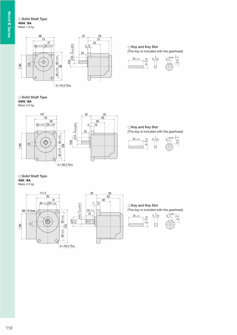
112
Solid Shaft Type4GN�RAMass: 1.6 kg
15
�80 40
�0.
2540
�0.
25
98
28�0.25 28�0.25
9874
34
337
9
7343
8332
250
10�
0.01
5(h
7)
4�5.5 Thru
�
Solid Shaft Type5GN�RAMass: 2.0 kg
29�0.25 29�0.2539
78107
12 45�
0.25
45�
0.25
104
4�6.5 Thru
4 1048
83
25
36
9332
12
�0.
018
(h7)
0
�90
�
Solid Shaft Type5GE�RAMass: 2.5 kg
7 1248
83
50�
0.25
50�
0.25
118
117.582
30�0.25 30�0.25
41
17 34
9338
4�8.5 Thru
�90
15
�0.
018
( h7)
0M5 10 Deep25
17
29�0.5
�
Key and Key Slot (The key is included with the gearhead)
25�0.2 4 0�0.040
2.5
0�0.
1
4�0.
03 0
4�0.03 0
�
Key and Key Slot (The key is included with the gearhead)
25�0.2 4 0�0.040
2.5
0�0.
1
4�0.
03 0
4�0.03 0
�
Key and Key Slot (The key is included with the gearhead)
25�0.2 5 0�0.040
3 0�0.
1
5�0.
03 0
5�0.03 0
�
Wo
rld K
Series

113
Dimensions of the Gearhead Mounting SurfaceAllow at least 8 mm for the thickness of the mounting plate and use screws of the appropriate length.
A�0.25
B�0.
25C�
0.25
8 mm min.
D
min
.
4�E
Cross Section XX
X
X
�
Mounting Method for Hollow Shaft Type Gearhead�Example of Mounting the Load
These diagrams show how to mount loads depending on the shape of the shaft.The tolerance of the inner diameter for the hollow shaft is finished as H8, and "key slot" processing is given to mount the load shaft.The recommended tolerance of the load shaft is h7. Use the key provided with the product by fastening it to the shaft. Apply a coating of molybdenum disulfide or similar grease to the inner diameter of the load shaft to prevent binding. Recommended load shaft dimensions are shown on the right.
�(Unit = mm)
ModelInner Diameter of Hollow Shaft
H8Recommended Load Shaft Diameter
h7
4GN�RH 15� 0.027 0
15 0� 0.018
5GN�RH 15� 0.027 0
15 0� 0.018
5GE�RH 17� 0.027 0
17 0� 0.018
Enter the gear ratio in the box (�) within the model name.�
Stepped Load Shaft
Load Shaft
Hollow Shaft
Spacer
Flat Washer
Bolt (M6)
Spring Washer
Retaining Ring for Hole
� Straight Load Shaft
Spacer
Load Shaft
Hollow Shaft
Spacer
Flat Washer
Bolt (M6)
Spring Washer
Retaining Ring for Hole
�
Note:If the bolt extends out more than 4 mm from the end of the hollow shaft, a safety cover can not be installed. (Hollow shaft type gearheads include safety covers.)
(Unit = mm)
Shaft Type Model A B C D E
Hollow Shaft4GN�RH 56 25 55 15 5.5
5GN�RH 58 33 57 15 6.5
5GE�RH 60 33 67 17 8.5
Solid Shaft4GN�RA 56 25 55 35 5.5
5GN�RA 58 33 57 37 6.5
5GE�RA 60 33 67 35 8.5
Enter the gear ratio in the box (�) within the model name.�
Wo
rld K
Series
Ind
uctio
n M
oto
rsR
eversible M
oto
rsE
lec
trom
ag
ne
tic B
rak
e
Mo
tors
Torq
ue M
oto
rsR
igh
t-An
gle
Gearh
eads
Bra
ke
Pa
ck
SB5
0W
Accesso
ries2
-Po
le,
Hig
h-S
peed
Typ
e

114
Brake Pack for Standard AC Motors
SB50W
Safety Standards and CE MarkingStandards Certification Body Standards File No. CE Marking
UL 508UL E91291
Low Voltage DirectivesEMC Directives
CSA C22.2 No.14EN 50178EN 60950-1
Conform to EN Standards
The EMC value changes according to the wiring and layout. Therefore, the final EMC level must be checked with the brake pack incorporated in the user’s equipment.
�
�
Features
Four Functions in One Integrated UnitThe SB50W provides instantaneous stop, forward/reverse operation, electromagnetic brake control and thermal protector open detection functions✽.
Thermal protector open detection function (Available only when combined with a motor having a built-in thermal protector) When the motor’s thermal protector (overheat protection device) is activated, the SB50W outputs an alarm signal and automatically cuts the power supply to the motor. The motor will not restart by itself, even after the temperature drops and the thermal protector recovers, until the power is cycled. Possible to reset the alarm through external signals.
Wide Voltage Range of 100 to 230 VACThe SB50W covers a single-phase voltage range of 100 to 230 VAC �10%, 50/60 Hz, accommodating all of the world's key voltage specifications.
Conforms to Safety StandardsThis is the world first brake pack which conforms to safety standards. The CE marking is used in accordance with the EMC directives and low voltage directives.
��
✽
�
�
Supports Motors with 1 to 90 W OutputThe SB50W can be used with induction, reversible, electromagnetic brake and watertight, dust-resistant motors with an output range of 1 to 90 W.
Switchable Sink/Source LogicSelect the sink mode or source mode for the input/output circuit. You can change the setting at any time.
�
�
The SB50W provides instantaneous stop, forward/reverse operation, electromagnetic brake control and thermal protector open detection functions integrated into one unit. These brake packs can sense when the thermal protector is opened, further ensuring the safety of your equipment.
RoHS-Compliant
Wo
rld K
Series

115
Applicable Products
World K Series1 W�90 W
Induction Motors✽
Reversible MotorsElectromagnetic Brake Motors
Except for 2-pole type
�
✽
Braking CurrentWhen a motor is stopped suddenly, a large half-wave rectified current flows through the motor for approximately 0.2 to 0.4 seconds. When connecting a circuit breaker, fuse or transformer, refer to the table below for the braking current (peak value) and select its current capacity.
Motor Output PowerBraking Current [A] (Peak Value)
100/110/115 VAC 200/220/230 VAC1 W 1.0 0.3✽
6 W 1.5 1.015 W 4.5 2.525 W 7.5 4.040 W 12 7.060 W 18 8.5
90 W 26 17
Can be used only for 200 VAC.
�
✽
System Configuration
Mounting Brackets (Accessories)(➜ Page 121)
Flexible Couplings (Accessories)(➜ Page 123)
�Example of System Configuration
AC Power Supply Gearhead (Sold separately)
Capacitor Cap✽ (Included with motor)Insulating cap for capacitor terminal section.✽
Capacitor (Included with motor)
SB50WBrake Pack
AC Motor (Sold separately)
Flush Mounting Socket (Included with brake pack)
(Sold separately)
Programmable Controller
(Body)
Mounting Bracket
SOL4M5 MCL301012
Flexible Coupling
SB50W
Brake PackLong Life,
Parallel-Shaft4GN25S
Motor(Pinion Shaft)
4IK25GN-CW2E
: Required under this system.: Selectable according to necessity. Oriental Motor provides.
24 VDC Power Supply
For motors other than those recognized by standards, the cap is sold separately.
The system configuration shown above is an example. Other configurations are available.
Specifications
ModelPower Supply
VoltageFrequency
Applicable Motor Output Voltage
FunctionsPower Source
for ControlInput Signals Output Signals
Braking CurrentDuration
SB50WSingle-phase100-230 VAC
�10%50/60 Hz 1 W�90 W
Instantaneous stopForward/reverse operationElectromagnetic brake control (Electromagnetic brake motors) Thermal protector open detection (Alarm output)Sink/Source logic switch
24 VDC �10%0.1 A min.
CW, CCW, FREE/ALARM-RESET
Input specificationsPhotocoupler input Input impedance 4.7 k�24 VDC �10%
ALARM
Output specificationsOpen collector output External use conditions 26.4 VDC max. 10 mA min.
Approximately 0.2�0.4 seconds
General SpecificationsItem Specifications
Insulation Resistance100 M� or more when measured by a 500 VDC megger between the power supply input terminal and the signal input terminal after rated motor operation under normal ambient temperature and humidity.
Dielectric StrengthSufficient to withstand 3.0 kV at 50 Hz or 60 Hz applied between the power supply input terminal and the signal input terminal for 1 minute after rated motor operation under normal ambient temperature and humidity.
Ambient Temperature 0C��40C (nonfreezing)Ambient Humidity 85% or less (noncondensing)Degree of Protection IP10
�
�
�
�
Wo
rld K
Series
Ind
uctio
n M
oto
rsR
eversible M
oto
rsE
lec
trom
ag
ne
tic B
rak
e
Mo
tors
Torq
ue M
oto
rsR
igh
t-An
gle
Gearh
eads
Bra
ke
Pa
ck
SB5
0W
Accesso
ries2
-Po
le,
Hig
h-S
peed
Typ
e

116
Dimensions (Unit = mm)
SB50WMass: 0.1 kg
5.5 0.7
�44
.6
�48
70.5
�� Flush Mounting Socket
(Included with brake pack)
40�0.2
9.5
50 max.
35.4
70 m
ax.
4
7.8
31.2 max.1.2 5
4.53
2�4.5
11�M3.5Screws
� Flush Mounting Socket Panel Cut-Out
2�4.5 Mounting Holes
40�0.2
�
Induction Motors
Over
run
[Rot
atio
ns]
50 Hz60 Hz
1 W
1.0
1.5
2.0
2.5
0.005 0.010 0.015 0.020 0.025 0.0300Load Inertia
�Ov
erru
n [R
otat
ions
]6 W
1.0
1.5
2.0
0.025 0.050 0.075 0.100 0.1250
50 Hz60 Hz
Load Inertia
Over
run
[Rot
atio
ns]
50 Hz60 Hz
15 W
1.0
1.5
2.0
0.05 0.10 0.15 0.20 0.250Load Inertia
Over
run
[Rot
atio
ns]
50 Hz60 Hz
25 W
1.0
1.5
2.0
0.1 0.2 0.3 0.4 0.5 0.60Load Inertia
Over
run
[Rot
atio
ns]
50 Hz60 Hz
40 W
1.0
1.5
2.0
0.25 0.50 0.75 1.00 1.250Load Inertia
Over
run
[Rot
atio
ns]
50 Hz60 Hz
60 W
1.0
1.5
2.0
2.5
0.5 1.0 1.5 2.00Load Inertia
Over
run
[Rot
atio
ns]
50 Hz60 Hz
90 W
1.0
1.5
2.0
0.5 1.0 1.5 2.00Load Inertia
Braking Characteristics (Reference Values)�
Wo
rld K
Series

117
Electromagnetic Brake Motors
Over
run
[Rot
atio
ns]
50 Hz60 Hz
6 W
1.0
1.5
2.0
0.025 0.050 0.075 0.100 0.1250Load Inertia
�
Over
run
[Rot
atio
ns]
50 Hz60 Hz
15 W
0.5
1.0
1.5
0.05 0.10 0.15 0.20 0.250Load Inertia
Over
run
[Rot
atio
ns]
50 Hz60 Hz
25 W
0.5
1.0
1.5
0.1 0.2 0.3 0.4 0.5 0.60Load Inertia
Over
run
[Rot
atio
ns]
50 Hz60 Hz
40 W
1.0
1.5
2.0
0.25 0.50 0.75 1.00 1.250Load Inertia
Over
run
[Rot
atio
ns]
50 Hz60 Hz
60 W
1.0
1.5
2.0
0.5 1.0 1.5 2.00Load Inertia
Over
run
[Rot
atio
ns]
50 Hz60 Hz
90 W
1.0
1.5
2.0
0.5 1.0 1.5 2.00Load Inertia
Reversible MotorsOv
erru
n [R
otat
ions
]
50 Hz60 Hz
1 W
1.0
1.5
2.0
2.5
0.005 0.010 0.015 0.020 0.025 0.0300Load Inertia
�
Over
run
[Rot
atio
ns]
50 Hz60 Hz
6 W
0.5
1.0
1.5
0.025 0.050 0.075 0.100 0.1250Load Inertia
Over
run
[Rot
atio
ns]
50 Hz60 Hz
15 W
0.5
1.0
1.5
0.05 0.10 0.15 0.20 0.250Load Inertia
Over
run
[Rot
atio
ns]
50 Hz60 Hz
25 W
0.5
1.0
1.5
0.1 0.2 0.3 0.4 0.5 0.60Load Inertia
Over
run
[Rot
atio
ns]
40 W
1.0
2.0
0.25 0.50 0.75 1.0 1.250
1.5
50 Hz60 Hz
Load Inertia
Over
run
[Rot
atio
ns]
50 Hz60 Hz
60 W
1.0
1.5
2.0
0.5 1.0 1.5 2.00Load Inertia
Over
run
[Rot
atio
ns]
50 Hz60 Hz
90 W
1.0
1.5
2.0
0.5 1.0 1.5 2.00Load Inertia
Wo
rld K
Series
Ind
uctio
n M
oto
rsR
eversible M
oto
rsE
lec
trom
ag
ne
tic B
rak
e
Mo
tors
Torq
ue M
oto
rsR
igh
t-An
gle
Gearh
eads
Bra
ke
Pa
ck
SB5
0W
Accesso
ries2
-Po
le,
Hig
h-S
peed
Typ
e

118
Connection and Operation
Names and Functions of Brake Pack Parts
q
w
e
r
��
No. Name Factory Setting Functions
�POWER Indicator (Green)
− Lit when 24 VDC is supplied.
� ALARM Indicator (Red) − Lit when the ALARM output is "OFF."
�Motor OutputSelect Switch
60�90 W Used to set the motor output.
�SINK/SOURCESelect Switch
SINKUsed to switch between Sink/Source for the control signal output.
Connection DiagramsThe wiring diagram is for when the SINK/SOURCE select switch is set to the "SINK" side.
Induction Motors/Reversible Motors
ALARM Output
CCW Operation InputCW Operation Input
Mot
or Motor
(Term
inal B
ox Ty
pe)
Black
Brake Pack Terminal No.
RedWhite
CapacitorCapacitor
GND
Brake Release Input
ON
ON
24 VDC0.1 A min.
�
�
LAC Power Supply✽
N
LAC Power Supply✽
N
✽Single-phase 100/110/115 VAC, single-phase 200/220/230 VAC
FG
ON
ON 22
1
6854
79
1Z2U2U1
�24 VDC
1111
Electromagnetic Brake Motors
CW Operation InputCCW Operation Input
GND
Brake Release Input
Elec
trom
agne
ticBr
ake
Mot
orRedWhite
Black
CapacitorOrangeOrange
L
NON
ON
Brake Pack Terminal No.
2
�
�24 VDC0.1 A min.
FG
AC Power Supply✽
1
10
6854
79 ALARM Output
11
�24 VDC
✽Single-phase 100/110/115 VAC, single-phase 200/220/230 VAC
�
�
�
Terminal Arrangement for Flush Mounting SocketTerminal
No.Signal Name Description
� Motor/Capacitor Connect the motor and capacitor.
� AC Power Input (L)Single-phase 100�115 VACSingle-phase 200�230 VAC
� NC Not used. Leave this terminal unconnected.
�✽1 Brake Release Input✽2 Not an instantaneous stop but a natural stop ALARM-RESET Input Reset ALARM Output.
� CCW Operation Input✽3 Motor runs in the CCW direction during "ON."
� DC Power Input �24 VDC input
GND GND
CW Operation Input Motor runs in the CCW direction during "ON."
� ALARM OutputTurns "OFF" when the motor's thermal protector is "open."
� Electromagnetic Brake✽4 Connect to the electromagnetic brake.
Motor/Capacitor Connect the motor and capacitor.
1 Functions as a brake release input during normal operation, and as an ALARM-RESET input when the ALARM output is OFF.
2 Releases the electromagnetic brake for electromagnetic brake motors. 3 Not used with an induction motor with four lead wires.4 Only for electromagnetic brake motors.
Notes:The input-signal voltage is 24 VDC�10% and 0.1 A or more.Minimize the length of the motor cable and the input/output signal cable to reduce EMI.Use a cable of AWG18 (0.75 mm2) or more in diameter for the motor cable and power cable.Be sure to connect the GND terminal to GND (negative side) of the external controller, or the unit will not operate.
�
✽
✽
✽
✽
���
�
Wo
rld K
Series

119
I/O Signal CircuitThe I/O signal circuit can be switched between the sink mode and source mode using the sink/source select switch on the brake pack. The factory setting is the sink mode.
Sink Logic
Input Circuit
854
DC Power Input
24 VDC
Brake Pack
Input✽4.7 k� 56
0�
✽ CW Operation InputCCW Operation InputBrake Release Input
6
Output Circuit
24 VDC
Brake Pack
4.7 k�
0 VGND
ALARM Output9
7
Source Logic
Input Circuit
854
24 VDC
Brake Pack
GND
Input✽4.7 k�
560
�
✽ CW Operation InputCCW Operation InputBrake Release Input
7
Output Circuit
24 VDC
Brake Pack
4.7 k�ALARM Output
DC Power Input6
9
�
�
•
•
�
•
•
Timing Chart
AC Power Supply ONOFF
CW Operation Input✽1 ONOFF
CCW Operation Input✽1 ONOFFONOFF
CWCCW
CWCCW
CW
Braking BrakingReversing
Braking Natural Stop
StopStopStopStopOperation Operation Operation Operation
Brake Release Input
Electromagnetic BrakeClockwise
RotationActio
nM
ovem
ent
CounterclockwiseRotation
Motor
Holding Holding Holding Holding Holding
DC Power Supply ONOFF
✽4
✽1 Turn on CW operation input, CCW operation input, and brake release input after turningon AC power.The motor does not operate if they are input ahead of AC power.The ALARM indicator will light and ALARM output will switch to "OFF."
✽2 The brake release input becomes ALARM-RESET input when the ALARM output is OFF.✽3 Only for electromagnetic brake motors.✽4 The induction motor will not accommodate instantaneous forward/reverse switching.
✽3
✽1✽2
CW Operation InputTurning the CW operation signal to "ON" causes the motor's output shaft to turn in the CW direction. Turning it to "OFF" triggers an instantaneous stop.
CCW Operation InputTurning the CCW operation signal to "ON" causes the motor's output shaft to turn in the CCW direction. Turning it to "OFF" triggers an instantaneous stop.If both the CW and CCW operation signals are simultaneously turned to "ON," the CW operation signal will take priority.Therefore, the wiring must be changed with an induction motor having four lead wires.
Brake Release Input [ALARM-RESET Input]Functions as a brake release input during normal operation, and as an ALARM-RESET input when the ALARM output is OFF.
When normal: [Brake Release Input]Turning the brake release signal to "ON" disables both the electronic brake and electromagnetic brake. When the CW and CCW operation signals are turned to "OFF," the motor operates via inertial force before coming to a natural stop. When the motor is stationary, the electromagnetic brake is not activated, so the motor's output shaft can be moved freely.Turning the brake release signal to "OFF" (or leaving the signal unconnected) and turning both CW and CCW operation signals to "OFF" will activate the electronic brake and electromagnetic brake, bringing the motor to an instantaneous stop. Once the motor stops, the electronic brake will release automatically. However, the electromagnetic brake will continue to operate and hold the load.
When ALARM output is OFF: [ALARM-RESET Input]When ALARM output is turned OFF, turn all input signals "OFF" and input 0.5 seconds or more for ALARM-RESET input.Wait at least 0.5 seconds after turning the ALARM-RESET input OFF before restarting operation.
0.5 s min.
Brake Release InputALARM-RESET Input
Brake Release Input Brake Release Input
ALARM Output
ON or OFF ON or OFF
ONON
ON
0.5 s min.
0.5 s max.
ALARM-RESET Input
Turns to "OFF" whenthe ALARM is output.
ALARM Activation ALARM Deactivation
It is also possible to deactivate the alarm by turning off the power and turning it on again. Turn off the DC or AC power, and turn all input signals "OFF" before turning on the power again.
�
�
�
�
•
•
Wo
rld K
Series
Ind
uctio
n M
oto
rsR
eversible M
oto
rsE
lec
trom
ag
ne
tic B
rak
e
Mo
tors
Torq
ue M
oto
rsR
igh
t-An
gle
Gearh
eads
Bra
ke
Pa
ck
SB5
0W
Accesso
ries2
-Po
le,
Hig
h-S
peed
Typ
e

120
ALARM Output (Thermal Protector Open Detection)Since the SB50W ALARM output function detects the operations of the thermal protector, the current flowing in the motor is monitored. Operation occurs under the following conditions:When the thermal protector built-in to the motor is openedWhen there is improper connection/disconnection of the power supply cable and motor cableWhen the input signal is turned "ON" before the AC power is turned onWhen the AC power is turned off while the motor is in operation or while it is stopped
In the above conditions, state of the SB50W ALARM output is "OFF," the ALARM indicator lamp (red) on the panel lights up, and power supply to the motor is stopped.With electromagnetic brake motors, the brake is activated in order to hold the load in position.
When the DC power is turned on, the alarm indication lamp lights up instantaneously, but this is not an abnormality.
Limiting Resistor2.7 k� or more 24 VDC
External Controller Brake Pack
GND
ALARM Output
Photocoupler
7
9
Use a power source of 26.4 VDC or less, and limit the output current to 10 mA or less.
Operating/Braking Repetition CycleThe repeated operation and braking of a motor will cause about a temperature increase in the motor and brake pack, thereby limiting the continuous operating time.Observe the repetition cycle given in the table below for the operation and braking of the motor. The motor may generate heat depending on the conditions in which it is driven. Ensure that the temperature of the motor case does not exceed 90˚C.
Motor Output Power Repetition Cycle1 W�25 W 2 seconds or more
40 W�90 W 4 seconds or more
(A repetition cycle of two seconds represents operation for one second and stopping for one second.)
�
••
•
•
✽
�
Wo
rld K
Series

121
Motor/Gearhead Mounting Brackets Mounting Brackets for attaching and securing a motor and gearhead. They are high-strength type, which can be used with high power motors/gearheads. These brackets come with tapped holes. To mount the motor and gearhead, simply fasten with the screws provided to the gearhead. To mount the motor alone, mounting screws must be provided separately.
Please note that these mounting brackets cannot be used with the following products.Right-angle gearheads (RH type, RA type)
�
�
Accessories
For Motor Frame Size: �42 mm
Model: SOL0M3Mass: 85 g Material: Aluminum
Applicable Products0GN GearheadMotor with the flame size of �42 mm
��
�
Dimensions (Unit = mm)
72
7.4
91
4.4
20
21
2014
6241
88
56
18
44
48�
0.3
4�M3
40�
0.5
37.6
36
40
203
6
�
For Motor Frame Size: �60 mm
Model: SOL2M4Mass: 135 g Material: Aluminum
Applicable Products2GN GearheadMotor with the flame size of �60 mm
��
�
Dimensions (Unit = mm)
91
5.4
8.4
1525
50
54
50
36 22
108
6278
3093
4�M4
850
�0.
5 82
1
54
70�0.3
31
�
Wo
rld K
Series
Ind
uctio
n M
oto
rsR
eversible M
oto
rsE
lec
trom
ag
ne
tic B
rak
e
Mo
tors
Torq
ue M
oto
rsR
igh
t-An
gle
Gearh
eads
Bra
ke
Pa
ck
SB5
0W
Accesso
ries2
-Po
le,
Hig
h-S
peed
Typ
e

122
For Motor Frame Size: �70 mm
Model: SOL3M5Mass: 175 g Material: Aluminum
Applicable Products3GN GearheadMotor with the flame size of �70 mm
��
�
Dimensions (Unit = mm)
2373
64
60
55
72
11810
5.4
8.4
1.5
88
18
60.5
92
55�
0.5
4�M5
10335
30
36
16
82�
0.3
�
For Motor Frame Size: �80 mm
Model: SOL4M5Mass: 210 g Material: Aluminum
Applicable Products4GN GearheadMotor with the flame size of �80 mm
��
�
Dimensions (Unit = mm)
7 24
60
3
68
960
�0.
5 102
40112
1635
101.
55.
4
41
128
1
8298
8.4
67
4�M5
73
94�0.3
�
For Motor Frame Size: �90 mm
Model: SOL5M6Mass: 270 g Material: Aluminum
Applicable Products5GN Gearhead5GE GearheadMotor with the flame size of �90 mm
��
�
Dimensions (Unit = mm)
26
65
93
80
83
966
�0.
5 112
1
50128
11 1.5
6.4
43
146
104�0.3
73.5
92112
9.4
1740
4�M6
�W
orld
K S
eries

123
Flexible Couplings These products are the clamping type couplings to connect between the shaft of motor/gearhead and the shaft of the equipment to be connected.Once the motor and gearhead are determined, the coupling can be done.
�
FeaturesCouplings come with shaft holes and have standardized combinations for different diameter shaft holes.Characteristics are the same for clockwise and counterclockwise rotation.Oil-resistant and electrically insulated.Aluminum alloy construction.The shaft being driven is not damaged, since shafts are joined by clamping.Easy installation due to a separated hub and sleeve design.
��
�
���
�
Gearhead Model Coupling Type
0GN�K MCL20
2GN�S MCL20MCL30
3GN�S MCL304GN�S4GN�RA
MCL30MCL40
5GN�S5GN�RA
MCL30MCL40
5GE�S5GE�RA
MCL40MCL55
Type of coupling varies depending on condition of the load. ✽
Capacitor Cap Insulating cap for capacitor terminal section.
(Example of use)
A
B
Use a capacitor cap suitable for the external dimensions (A�B) of the capacitor.Material: Polyvinyl chlorideOur capacitor caps are recognized by UL.UL File No. E56078
�
ModelExternal Dimensions
A�B(Unit � mm)
Applicable CapacitorModel
CHC5835AUL 58�35 CH400300A
Note:Ten capacitor caps are included in one bag.Order capacitor caps in a multiple of one bag.
CR Circuit for Surge Suppression This product is used to protect the contacts of the relay and/or switch used for controlling the reversal of direction and the electromagnetic brake.
�
Model: EPCR1201-2250 VAC (120 �, 0.1 �F)
� Dimensions (Unit = mm)
Mass: 5 g
23.5�
0.5
8.5�0.517.5�0.5 15 min.
0.8
�0.0
5
20
�
Wo
rld K
Series
Ind
uctio
n M
oto
rsR
eversible M
oto
rsE
lec
trom
ag
ne
tic B
rak
e
Mo
tors
Torq
ue M
oto
rsR
igh
t-An
gle
Gearh
eads
Bra
ke
Pa
ck
SB5
0W
Accesso
ries2
-Po
le,
Hig
h-S
peed
Typ
e
For more information please contact:
Specifications are subject to change without notice.This catalogue was published in July, 2006.
This product is manufactured at a plant certified with the international standards ISO 9001 (for quality assurance) and ISO 14001 (for systems of environmental management).
This printed material uses recycled paper and soy inks. This combination is environmentally friendly.
ORIENTAL MOTOR (EUROPA) GmbH www.orientalmotor.de
European Headquarters and Düsseldorf OfficeSchiessstraße 7440549 Düsseldorf, GermanyTel: 0211-5206700 Fax: 0211-52067099
Munich OfficeLiebigstraße 1485757 Karlsfeld, GermanyTel: 08131-59880 Fax: 08131-598888
Hamburg OfficeMeckelfelder Weg 221079 Hamburg, GermanyTel: 040-76910443 Fax: 040-76910445
Stuttgart Office
Tel: 073-35-924853 Fax: 073-35-924854
ORIENTAL MOTOR (UK) LTD. www.oriental-motor.co.ukUnit 5, Faraday Office Park,Rankine Road, Basingstoke,Hampshire RG24 8AH U.K.Tel: 01256-347090 Fax: 01256-347099
ORIENTAL MOTOR (FRANCE) SARLwww.orientalmotor.fr
France Headquarters32, Avenue de I'ile Saint Martin92737 Nanterre Cedex, FranceTel: 01 47 86 97 50 Fax: 01 47 82 45 16
Lyon Office10, Allée des Sorbiers69673 Bron Cedex, FranceTel: 04 78 41 15 02 Fax: 04 78 41 15 90
ORIENTAL MOTOR ITALIA s.r.l.www.orientalmotor.it
Italy HeadquartersVia A. De Gasperi, 8520017 Mazzo di Rho (Ml), ItalyTel: 02-93906346 Fax: 02-93906348
Bologna OfficeVia mori, 640054 Prunaro di Budrio (BO), ItalyTel: 051-6931249 Fax: 051-6929266
ORIENTAL MOTOR CO., LTD.www.orientalmotor.co.jp
Headquarters16-17, Ueno 6-chomeTaito-ku, Tokyo 110-8536, JapanTel: (03)3835-0684 Fax: (03)3835-1890
Printed in Japan 06U 3K 83600T