standard models - myw- · pdf filethe dt4200 series features a dedicated ic that hioki...
TRANSCRIPT

AC clamp-on measurement Frequency
Resistance Continuity check
Temperature Diode test
Capacitance ConductanceAC/DC automatic
detectionVoltage detection
function
DC voltage 600.0 mV to 1000 V
AC voltage 6.000 V to 1000 V
DC + AC voltage DT4281/4282 only
DC current 6.000 A to 10.00 A
AC current 6.000 A to 10.00 A
AC clamp-on measurement Frequency
Resistance Continuity check
Temperature Diode test
Capacitance ConductanceAC/DC automatic
detectionVoltage detection
function
DC voltage 600.0 mV to 1000 V
AC voltage 6.000 V to 1000 V
DC + AC voltage DT4281/4282 only
DC current 60.00 mA to 10.00 A
AC current 600.0 mA to 10.00 A
AC clamp-on measurement Frequency
Resistance Continuity check
Temperature Diode test
Capacitance ConductanceAC/DC automatic
detectionVoltage detection
function
DC voltage 600.0 mV to 1000 V
AC voltage 6.000 V to 1000 V
DC + AC voltage DT4281/4282 only
DC current 60.00 μA to 60.00 mA
AC current n/a
AC clamp-on measurement Frequency
Resistance Continuity check
Temperature Diode test
Capacitance ConductanceAC/DC automatic
detectionVoltage detection
function
DC voltage 600.0 mV to 1000 V
AC voltage 6.000 V to 1000 V
DC + AC voltage DT4281/4282 only
DC current n/a
AC current n/a
AC clamp-on measurement Frequency
Resistance Continuity check
Temperature Diode test
Capacitance ConductanceAC/DC automatic
detectionVoltage detection
function
AC voltage 6.000 V to 1000 V
DC + AC voltage DT4281/4282 only
DC current n/a
AC current n/a
*According to Hioki research conducted in April 2015.
Featuring the world’s fastest DMM engine*The DT4200 series features a dedicated IC that Hioki developed in-house in order to deliver unprecedented measurement speed.
For laboratory and
research useDT4252
For laboratories and R&D applications where you wish to measure a wide variety of parameters.
For instrumentation and air-
conditioning workDT4253Measure
instrumentation, air-conditioning equipment,
and gas-burning devices.
Voltage For electrical work in the fiel
DT4255Designed for
maximum safety with voltage measurement
terminals that are protected by a fuse.
Multifunction modelDT4256
Delivers maximum functionality for use in a wide range of
settings.
Standard modelsIntroducing a line of field-optimized instruments that
can be chosen based on the application at handDCV typical accuracy: ±0.3% rdg. ±3 dgt.
Measurement categories: CAT III (1000 V) / CAT IV (600 V)
Supported measurement parameter Supported measurement parameter (with model-specific variations) Unsupported measurement parameter*The range figures given indicate the instrument’s measurement ranges (not the range of measurable values).
measurementonly model
DT4254Measure photovoltaic
modules and other high-voltage targets at
up to 1700 V DC.
DC voltage 600.0 mV to 1500 V
www. .com
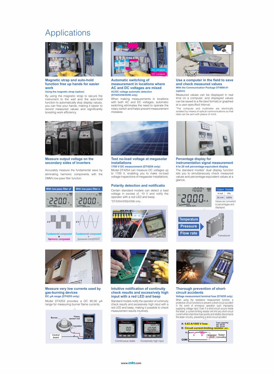
A: 0.63 A/1000 V fuseB: Circuit current-limiting resistor ( 5Ω )
COM
BA+
Testercircuitry
Protectivecircuit
Fuse capacity: AC: 50 kADC: 30 kA
0 V 0 V
Burner Flame sensor rod
Insulator
Control board
Values are converted to percentages and displayed.
Output Display4 mA 0%20 mA 100%
AC contactsDC contacts
Applications
Magnetic strap and auto-hold function free up hands for easier work
Automatic switching of measurement in locations where AC and DC voltages are mixed
Use a computer in the field to saveand check measured values
By using the magnetic strap to secure the instrument to the wall and the auto-hold function to automatically stop display values, you can free your hands, making it easier to record measured values and significantly boosting work efficiency.
When making measurements in locations with both AC and DC voltages, automatic switching eliminates the need to operate the rotary switch and helps prevent measurement mistakes.
Measured values can be displayed in real time on a computer, and displayed values can be saved to a file (text format) or graphed at a user-specified interval.*The computer and multimeter are electricallyisolated by means of optical communications so that data can be sent with peace of mind.
Using the magnetic strap (option) AC/DC voltage automatic detection (DT4253/54/55/56 only)
With the Communication Package DT4900-01 (option)
Measure output voltage on the secondary sides of inverters
Percentage display for instrumentation signal measurement
Thorough prevention of short-circuit accidents
Test no-load voltage at megasolar installations
Polarity detection and notificatio
1700 V DC measurement (DT4254 only) 4 to 20 mA percentage-equivalent display
Voltage measurement terminal fuse (DT4255 only)
Accurately measure the fundamental wave by eliminating harmonic components with the DMM’s low-pass filter function.
The standard models’ dual display function lets you to simultaneously check measured values and percentage-equivalent values at a glance.
When using the resistance measurement function, a protective circuit functions to prevent a short-circuit accident in the event of erroneous operation such improperly supplying voltage input. Even if a short-circuit occurs inside the tester, a current-limiting resistor will limit any short-circuit current while a fast-blow fuse quickly and reliably disconnects the tester circuitry, preventing a short-circuit accident.
Model DT4254 can measure DC voltages up to 1700 V, enabling you to make no-load voltage inspections of megasolar installations.
Certain standard models can detect a load voltage in excess of -10 V and notify the operator with a red LED and beep.*DT4254/4255/4256 only.
Temperature
Pressure
Flow rateTransducer
With low-pass filter of With low-pass filter o
Fundamental component
Harmonic component+
Fundamental component
Harmonic component+
Measure very low currents used by gas-burning devices
Intuitive notification of continuitycheck results and excessively high input with a red LED and beepDC μA range (DT4253 only)
Model DT4253 provides a DC 60.00 μA range for measuring burner flame currents.
Standard models notify the operator of continuity check results and excessively high input with a red LED and beep, making it possible to check measurement results intuitively.
Continuous state Excessively high input
www. .com

Field-Proven Strength and UsabilityDT4200 series
Robust design capable of withstanding a drop from a height of 1 m onto concrete
Fast, accurate measurement of the output voltage on the secondary side of an inverter
Outstanding viewing angle so display is easy to read at an angle or even in a dim location
Outstanding hands-free ease of use in the field when working with numerous measurement location
Extensive selection of probe tips that you can choose based on the measurement location, improving ease of measurement
True RMS measurement for accurate measurement of even distorted current waveforms
Rotary switch that’s easy to operate even when wearing gloves
The DT series can accurately measure the voltage on the secondary side of an inverter, just like a power meter. Its low-pass filter rejects harmonic components so that the fundamental wave can be isolated and accurately measured.
Current waveforms are often distorted, causing the average-value and true RMS measurement methods to yield different results. To obtain accurate readings, RMS measurement is indispensable.
Preventing instrument failure by keeping out dust
With screw terminals
Secure the instrument on the wall so that you don’t have to hold it.
In deep-set locations that can’t be reached with other probes
The display automatically stops once the measured value stabilizes.
Press the MEM key to save measured values in the instrument’s internal memory.
For clamping around the target busbar
To test our products’ ability to withstand mechanical shock, we repeatedly drop them from a height of at least 1 m until they break. This drop-testing regime leads to more robust products by fostering a series of design improvements.
If dust gets into the instrument’s enclosure, it can cause the device to fail. Since dust can get into the instrument especially easily through the gap around the rotary switch, the DT4200 series incorporates a dust-proof part known as an O-ring where the rotary switch is mounted to improve the device’s dust resistance.
It’s hard to carry out work tasks smoothly when you’re juggling a measuring instrument, probes, recording paper, and other supplies. Field concerns like these are resolved by the DT4200’s magnetic strap, auto-hold function, and ability to save results in its internal memory. These capabilities boost work efficiency and help reduce work times.*The auto-hold function is available exclusively in high-end and standard models. The ability to save results in internal memory is available exclusively in high-end models.
*Compatible probe tips vary with the DMM model. Please see page 16. The optional Connection Cable L4930 is required in order to use the probes shown at the left.
The DT4200 series features a display with a wide viewing angle and a backlight function so that it’s easy to read, even when you can’t view the screen from the front or when making measurements in a dim location.
With the DT4200, you can choose the probe type that best suits your measurement location, making it possible to measure in areas that can’t be reached with conventional probes and busbars that you wish to clamp between probes.
With low-pass filter of With low-pass filter o True RMS method measured value
Average-value method measured value
Drop tester
The DT4200’s rotary switch is designed to be easy to turn even when wearing thick work gloves, for example while working in hazardous measurement locations or harsh conditions.
www. .com

Engineered based on extensive customer feedback, the Hioki Digital Multimeter DT4200 series delivers the design
and quality needed in order to ensure safety in field measurement.
To ensure operators’ ability to use measuring instruments safely, IEC 61010 classifies the locations in which instruments are used into a series of safety-based measurement categories (ranging from CAT II to CAT IV). Using an instrument that does not satisfy the required safety level can lead to an electrical accident.
All development, design, and manufacturing processes for almost all Hioki digital multimeters are carried out at our Head Office in Nagano Prefecture. Some of the industry’s most advanced technological capabilities enable us to deliver products of the highest possible quality.
Safe measurement requires use of an instrument that suits the measurement location.
Designed and manufactured in Japan to ensure high quality and guaranteed with a 3-year warranty for peace of mind
CAT IV 600 VMeasurement category suited to the location of use
Terminal-to-ground voltage
Safe testers that protect workers from dangerous accidents
High-end models CAT III 1000 V / CAT IV 600 V
Standard models CAT III 1000 V / CAT IV 600 V
Pocket models CAT III 600 V / CAT IV 300 V
3-yearwarranty
Service wires
Distributionpanel
L1
N
L2
Line voltage: 100 V
TV: 100 V
100V
100V
Air conditioner: 200 V
Line voltage: 200 V
Line voltage: 100 V
Pole-mounted transformerElectric
wires
Ground (0 V)
Measurement categories
Terminal-to-ground voltage
Buried wires
TransformerOutlet Outlet
Serviceconnection
Servicewires
Power meter Distribution panel
Distribution panel
Fixed equipment
www. .com

DC Voltage *1 : DT4252 only *2 : DT4254 only
Range Accuracy Input Impedance
High precision 600mV range*1 ±0.2 %rdg. ±5 dgt. 10.2 MΩ ± 1.5 %
600.0 mV ±0.5 %rdg. ±5 dgt.11.2 MΩ ± 2.0 %
6.000 V
±0.3 %rdg. ±3 dgt.60.00 V 10.3 MΩ ± 2.0 %600.0 V
10.2 MΩ ± 1.5 %1000 V1500 V*2 ±0.3 %rdg. ±3 dgt.
Resistance Measurement DT4252/53/55/56 only
Range Accuracy Measurement Current Open-terminal Voltage600.0 Ω ±0.7 %rdg. ±5 dgt. Approx. 200 μA
DC1.8 V or less
6.000 kΩ±0.7 %rdg. ±3 dgt.*1
Approx. 100 μA60.00 kΩ Approx. 10 μA600.0 kΩ Approx. 1 μA6.000 MΩ ±0.9 %rdg. ±3 dgt.*1 Approx. 100 nA60.00 MΩ ±1.5 %rdg. ±3 dgt.*1 Approx. 10 nA
Accuracy guarantee condition After zero adjustment has been performed
Continuity Check DT4252/53/55/56 only
Range Accuracy Measurement Current Open-terminal Voltage600.0 Ω ±0.7 %rdg. ±5 dgt. Approx.200 μA DC1.8 V or less
Continuity ON threshold Approx. 25Ω or less (continuous buzzer sound, red LED lights)Continuity OFF threshold Approx.245Ω or more
Diode Check DT4252/53/55/56 only
Range Accuracy Measurement Current Open-terminal Voltage1.500 V ±0.5 %rdg. ±5 dgt.*1 Approx. 0.5 mA DC5.0 V or less
Forward threshold Buzzer sounds intermittently at 0.15V to 1.5V, the red LED flashes
AC Clamp (AC Current) DT4253/55/56 only
RangeAccuracy40 to 1 kHz
10.00 A
±0.9 %rdg. ±3 dgt.
20.00 A50.0 A100.0 A200.0 A500 A1000 A
The optional 9010-50, 9018-50, or 9132-50 CLAMP ON PROBE is used.Accuracy does not include the error of the clamp-on probe.Crest factor 3 or lessAccuracy specification range Minimum 1% of range; add ±5 dgt. when measuring at or below 5% of range
Temperature DT4253 only
Thermocouple Type Range AccuracyK -40.0 to 400.0 ℃ ±0.5 %rdg. ±2 ℃
The optional K Thermocouple DT4910 is used. Accuracy does not include the error of the K thermocouple
Capacitance Measurement DT4252/53/55/56 only
Range Accuracy Measurement Current Open-terminal Voltage1.000 μF
±1.9 %rdg. ±5 dgt.
Approx. 10 n/100 n/1 μA
DC1.8 V or less10.00 μF Approx. 100 n/1 μ/10 μA100.0 μF Approx. 1 μ/10 μ/100 μA1.000 mF Approx. 10 μ/100 μ/200 μA10.00 mF ±5.0 %rdg. ±20 dgt. Approx. 100 μ/200 μA
FrequencyRange Accuracy
99.99 Hz
±0.1 %rdg. +1 dgt.999.9 Hz9.999 kHz
99.99 kHz (V AC Only)
Standard DT4252/DT4253/DT4254/DT4255/DT4256
*1 : DT4255 : ±0.5 %rdg. ±8 dgt.
AUTO V (Identification DT4253/54/55/56 only
RangeAccuracy
Input ImpedanceDC,40 to 500 Hz 500 or more to 1kHz
600.0 V ±2.0 %rdg. ±3 dgt. ±4.0 %rdg. ±3 dgt. 900 kΩ ± 20%1800 kΩ ± 20%*1
AC Voltage
RangeAccuracy
Input Impedance40 to 500 Hz 500 or more to 1kHz
6.000V
±0.9 %rdg. ±3 dgt. ±1.8 %rdg. ±3 dgt.
11.2 MΩ ± 2.0%//100 pF or less60.00V 10.3 MΩ ± 2.0%//100 or less600.0V
10.2 MΩ ± 1.5%//100 or less1000V
Crest factor 3 up to 4000 counts and reduces linearly to 2 at 6000 counts.Accuracyspecification range
For ACV, minimum 1% of range; add ±5 dgt. when measuring at or below 5% of range With the filter ON,the accuracy is not specified at 100Hz/500Hz or more
DCA Measurement DT4252/53/56 onlyRange Accuracy Input Impedance
60.00 μA ±0.8 %rdg. ±5 dgt. 1 kΩ±5 %600.0 μA ±0.8 %rdg. ±5 dgt. 1 kΩ±5 %6.000 mA ±0.8 %rdg. ±5 dgt. 15 Ω±40 %60.00 mA ±0.8 %rdg. ±5 dgt.*1 15 Ω±40 %*1
600.0 mA ±0.9 %rdg. ±5 dgt. 35 mΩ±30 %6.000 A ±0.9 %rdg. ±3 dgt.*2 35 mΩ±30 %10.00 A ±0.9 %rdg. ±3 dgt.*2 35 mΩ±30 %
ACA Measurement DT4252/56 only
RangeAccuracy
Input Impedance40 to 500 Hz 500 or more to 1kHz
600.0 mA*1 ±1.4 %rdg. ±5 dgt. ±1.8 %rdg. ±5 dgt. 35 mΩ±30 %6.000 A ±1.4 %rdg. ±3 dgt. ±1.8 %rdg. ±3 dgt. 35 mΩ±30 %10.00 A ±1.4 %rdg. ±3 dgt. ±1.8 %rdg. ±3 dgt. 35 mΩ±30 %
Crest factor 3 up to 4000 counts and reduces linearly to 2 at 6000 counts.Accuracy specification range Minimum 1% of range; add ±5 dgt. when measuring 300 counts or less
Electric Charge DT4254/55/56 only
Range Detection voltage range Detection Target FrequencyHi AC40 V to AC600 V
50 Hz / 60 HzLo AC80 V to AC600 V
During voltage detection, a continuous buzzer sounds and the red LED lights up.
*1 : DT4254
*1 : DT4256 only
*1 : DT4256 : ±1.8 %rdg. ±15 dgt. Input Impedance : 35 mΩ±30 %*2 : DT4252 : ±0.9 %rdg. ±5 dgt.
: DT4252 : DT4253 : DT4256
*1 : DT4252/4253 : ±5dgt.
(Accuracy guaranteed for 1 year, Post-adjustment accuracy guaranteed for 1 year)
www. .com
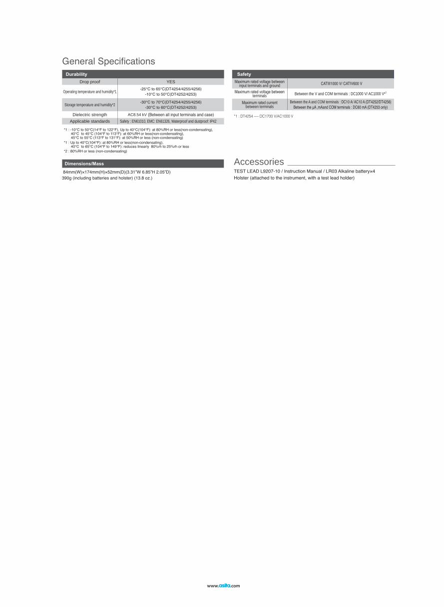
SafetyMaximum rated voltage between
input terminals and ground CATⅢ1000 V/ CATⅣ600 V
Maximum rated voltage between terminals Between the V and COM terminals : DC1000 V/ AC1000 V*1
Maximum rated current between terminals
Between the A and COM terminals : DC10 A/ AC10 A (DT4252/DT4256)Between the μA ,mAand COM terminals : DC60 mA (DT4253 only)
DurabilityDrop proof YES
Operating temperature and humidity*1 -25℃ to 65℃(DT4254/4255/4256)-10℃ to 50℃(DT4252/4253)
Storage temperature and humidity*2 -30℃ to 70℃(DT4254/4255/4256)-30℃ to 60℃(DT4252/4253)
Dielectric strength AC8.54 kV (Between all input terminals and case)Applicable standards Safety : EN61010, EMC: EN61326, Waterproof and dustproof: IP42
TEST LEAD L9207-10 / Instruction Manual / LR03 Alkaline battery×4 Holster (attached to the instrument, with a test lead holder)
General Specifications
*2 : 80%RH or less (non-condensating)
Accessories Dimensions/Mass
84mm(W)×174mm(H)×52mm(D)(3.31”W 6.85”H 2.05”D) 390g (including batteries and holster) (13.8 oz.)
*1 : DT4254 ---- DC1700 V/AC1000 V
*1 : -10°C to 50°C(14°F to 122°F), Up to 40°C(104°F): at 80%RH or less(non-condensating), 40°C to 45°C (104°F to 113°F): at 60%RH or less(non-condensating), 45°C to 55°C (113°F to 131°F): at 50%RH or less (non-condensating)*1 : Up to 40°C(104°F): at 80%RH or less(non-condensating), 40°C to 65°C (104°F to 149°F): reduces linearly 80%rh to 25%rh or less
www. .com
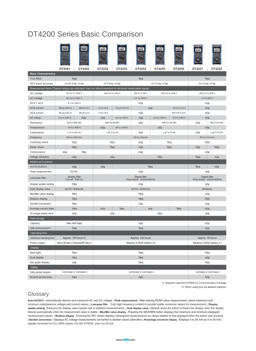
DT4200 Series Basic Comparison
Glossary
DT4281 DT4282 DT4252 DT4253 DT4254 DT4255 DT4256 DT4221 DT4222Basic Characteristics
True RMS Yes Yes YesDCV basic accuracy ±0.025 %rdg. ±2 dgt. ±0.3 %rdg. ±5 dgt. ±0.3 %rdg. ±3 dgt. ±0.5 %rdg. ±5 dgt.
Measurement items (Typical ranges are indicated; may not reflect maximum or minimum measurable signal)
DC voltage 60 mV to 1000 V 600 mV to 1000 V 600 mV to 1500 V 600 mV to 1000 V 600 mV to 600 V
AC voltage 60 mV to 1000 V 6 V to 1000 V 6 V to 600 V
DCV + ACV 6 V to 1000 V n/a n/aDCA current 600 μA to 600 mA 600 μA to 10 A 6 A to 10 A 60 μA to 60 mA n/a 60 mA to 10 A n/aACA current 600 μA to 600 mA 600 μA to 10 A 6 A to 10 A n/a 600 mA to 10 A n/aAC clamp 10 A to 1000 A n/a n/a 10 A to 1000 A n/a 10 A to 1000 A 10 A to 1000 A n/aResistance 60 Ω to 600 MΩ 600 Ω to 60 MΩ n/a 600 Ω to 60 MΩ n/a 600 Ω to 60 MΩ
Temperature -40℃ to 800℃ n/a -40℃ to 400℃ n/a n/aCapacitance 1 nF to 100 mF 1 μF to 10 mF n/a 1 μF to 10 mF n/a 1 μF to 10 mF
Frequency 99 Hz to 500 kHz 99 Hz to 99 kHz 99 Hz to 9.9 kHz
Continuity check Yes Yes n/a Yes YesDiode check Yes Yes n/a Yes n/a YesConductance n/a Yes n/a n/aVoltage detection n/a n/a Yes Yes n/aAdditional Functions
AUTO AC/DCV n/a n/a Yes Yes n/aPeak measurement DC/AC n/a n/a
Low-pass filter Analog filterCut-off : 630 Hz
Digital filterPass-band : 100Hz/500Hz
Digital filterPass-band : 100Hz/500Hz
Display update setting Yes n/a n/aHold display value AUTO / MANUAL AUTO / MANUAL MANUAL
Max/Min value display Yes Yes n/aRelative display Yes Yes YesDecibel conversion Yes n/a n/aPercentage conversion display Yes n/a Yes n/a Yes n/aDC voltage polarity check n/a n/a Yes n/aData storage
Capacity Max 400 data n/a n/aUSB communication*1 Yes Yes n/a Operating time
Continuous operating time Approx. 100 hours*2 Approx. 130 hours Approx. 40 hours
Power supply Alkaline (LR6) battery ×4 / Manganese(R6P) battery ×4 Alkaline (LR03) battery ×4 Alkaline (LR03) battery ×1
Display
Back light Yes Yes YesDual display Yes Yes n/aBar graph display n/a Yes Yes Safety
Safety standard categories CATⅢ1000 V/ CATⅣ600 V CATⅢ1000 V/ CATⅣ600 V CATⅢ600 V/ CATⅣ300 V
Mis-insertion prevention shutters Yes n/a n/a
Auto AC/DCV : Automatically detects and measures AC and DC voltage. | Peak measurement : After starting PEAK value measurement, check maximum and minimum instantaneous voltage and current values. | Low-pass filte : Cuts high frequency content to provide stable numerical values for measurement. | Display update setting : Reduces the display value update rate to stabilize measurements. | Hold display value : Manual: press the button to freeze the display. Auto: the display freezes automatically when the measurement value is stable. | Max/Min value display : Pressing the MAX/MIN button displays the maximum and minimum displayed measurement values. | Relative display : Pressing the REL button displays subsequent measurements as values relative to that displayed when the button was pressed. | Decibel conversion : Displays AC voltage measurements converted to decibel values (dbm/dbv) | Percentage conversion display : Displays 4 to 20 mA (or 0 to 20 mA) signals converted to 0 to 100% values. For the DT4253, only 4 to 20 mA.
*1. Requires optional DT4900-01 Communication Package*2. When using four AA alkaline batteries
www. .com
www. .com

HEADQUARTERS 81 Koizumi, Ueda, Nagano, 386-1192, Japan TEL +81-268-28-0562 FAX +81-268-28-0568 http://www.hioki.com / E-mail: [email protected]
HIOKI USA CORPORATION TEL +1-609-409-9109 FAX +1-609-409-9108 http://www.hiokiusa.com / E-mail: [email protected] information correct as of May 15, 2015. All specifications are subject to change without notice. series_DT4200E5-55M
DISTRIBUTED BYHIOKI (Shanghai) SALES & TRADING CO., LTD. TEL +86-21-63910090 FAX +86-21-63910360 http://www.hioki.cn / E-mail: [email protected]
HIOKI INDIA PRIVATE LIMITED TEL +91-124-6590210 FAX +91-124-6460113E-mail: [email protected]
HIOKI SINGAPORE PTE. LTD. TEL +65-6634-7677 FAX +65-6634-7477E-mail: [email protected]
HIOKI KOREA CO., LTD. TEL +82-2-2183-8847 FAX +82-2-2183-3360E-mail: [email protected]
Note: Company names and Product names appearing in this catalog are trademarks or registered trademarks of various companies.
• Thermal junction form: exposed weld• Sensor length: approx. 800 mm• Measurement temperature range
–40 to 260°C (thermocouple)–15 to 55°C (connector)
• Allowable tolerance:±2.5°C
MAGNETIC STRAP Z5004
THERMOCOUPLES (K) DT4910
CARRYING CASE C0200
COMMUNICATION PACKAGE (USB) DT4900-01• Communication cable• Communication adapter• PC software• Instruction manualOS: Windows 8.1/8/7, Vista (SP1 or later)
DT4220 Series
CARRYING CASE C0202DT4250/DT4280 Series
CARRYING CASE C0201
CARRYING CASE 3853
DT4250 Series DT4250 Series
TEST LEAD L9207-10Cable length 90 cm (2.9527 ft)with one each red and black caps
with cap
without capCAT III 1000V/CAT IV 600V
CAT II 1000V
DT4280/DT4250 Series(Bundled accessory)
TEST LEAD DT4911Cable length 54cm (1.77 ft)with one each red and black caps
with cap
without capCAT IV 300V/ CAT III 600V
CAT II 600V
DT4220 Series(Bundled accessory)
Adapter Model 9704 is required to connectAC CLAMP ON PROBES 9010-50, 9018-50 and 9132-50 to the DT4281, DT4253, DT4255, DT4256.
Product appearance
Model number 9010-50 9018-50 9132-50 Rated current AC 10/20/50/100/200/500 A AC 20/50/100/200/500/1000A
Amplitude accuracy (45 to 66Hz) ±2% rdg. ±1% f.s. ±1.5% rdg. ±0.1% f.s. ±3% rdg. ±0.2% f.s.
Frequency characteristics 40Hz to 1kHz:±6% rdg. 40Hz to 3kHz:±1% rdg. 40Hz to 1kHz:±1% rdg.
Output rate AC 0.2 V f.s. (For each range)
Max. circuit voltage AC600 V (50/60Hz)
Diameter φ46mm (1.81 in) or less φ55mm (2.17 in) or less, 80×20mm (3.15×0.79 in)
Dimensions, mass78W×188H×35D mm (3.07W × 7.40H × 1.38D in)
420g (14.8oz.),cord length 3m (9.84 ft)100W×224H×35D mm(3.94W ×8.82 H × 1.38D in)
600g(21.1oz.), cord length 3m(9.84 ft)
CONTACT PIN SET L4933 SMALL ALLIGATOR CLIP SET L4934
ALLIGATOR CLIP SET L4935
EXTENSION CABLE SET L4931GRABBER CLIP 9243
BUS BAR CLIP SET L4936 MAGNETIC ADAPTER SET L4937
TEST PIN SET L4932
CONVERSION ADAPTER 9704
DC70V/AC33V
CAT III 600V CAT III 1000V
CAT III 1000VCAT III 1000V /CAT IV 600V
CAT III 1000VCAT IV 600V
Length : 1.5m (4.9212 ft)With coupling connectors
CAT II 600VCAT III 300V
CAT III 1000VCAT IV 600V
L4933 and L4934 probe tips(at right) can be used on L9207-10/DT4911 test leads.
with one each red and black caps
50mm(1.97 in)
30mm(1.18 in)
Magnetφ6mm(0.24 in)
CAT III 600V CAT III 600V CAT III 600V
CONNECTION CABLE L4930Length : 1.2m (3.937 ft)
Compatible DMMs:DT4250 Series / DT4280 Series
TEST PIN SET L4938
BREAKER PIN L4939CAT III 600V
CAT III 600V (with cap)CAT II 600V (without cap)
Probe tips (at right) can be used on L4930 connection cables.
with one each red and black caps
48mm(1.89 in)φ2.6mm(0.15in)
22mm(0.87 in)φ3.7mm(0.15 in)
22mm(0.87 in)φ3.7mm(0.15 in)
ASITA s.r.l. Via Malpighi, 170 - 48018 Faenza (RA)
Tel. 0546 620559 - Fax 0546 620857 www.asita.com - [email protected]
L9207-10 / DT4911 Options
L4930 Options
AC CLAMP ON PROBES for DT4281, DT4253, DT4255, DT4256 (Adapter 9704 required for connection)
Other options