standard operating instruction - world …. move the monitor to face north – wind direction...
TRANSCRIPT

Standard Operating Instruction: Equipment Conformance
UNCONTROLLED COPY: WHEN PRINTED OR USED OUTSIDE THE ELECTRONIC QUALITY MANAGEMENT SYSTEM
Public Document Document Reference: NTL-SOI-VERCERT-001.2
Page 1 of 20
Standard Operating Instruction Operation and management of verification instrumentation for wind, temp/humidity,
rainfall and air pressure at weather offices
Document Reference: NTL-SOI-VERCERT-001
Document Type: Standard Operating Instruction
Version: 2
This document is controlled in terms of the South African Weather Services’ Quality Management System and may not be
edited, distributed or deemed obsolete without permission of the Management Quality Representative
Standard Operating Instruction: Equipment Conformance
UNCONTROLLED COPY: WHEN PRINTED OR USED OUTSIDE THE ELECTRONIC QUALITY MANAGEMENT SYSTEM
Public Document Document Reference: NTL-SOI-VERCERT-001.2
Page 2 of 20
SECTION A - Preliminary Informative Elements
Standard Operating Instruction: Equipment Conformance
UNCONTROLLED COPY: WHEN PRINTED OR USED OUTSIDE THE ELECTRONIC QUALITY MANAGEMENT SYSTEM
Public Document Document Reference: NTL-SOI-VERCERT-001.2
Page 3 of 20
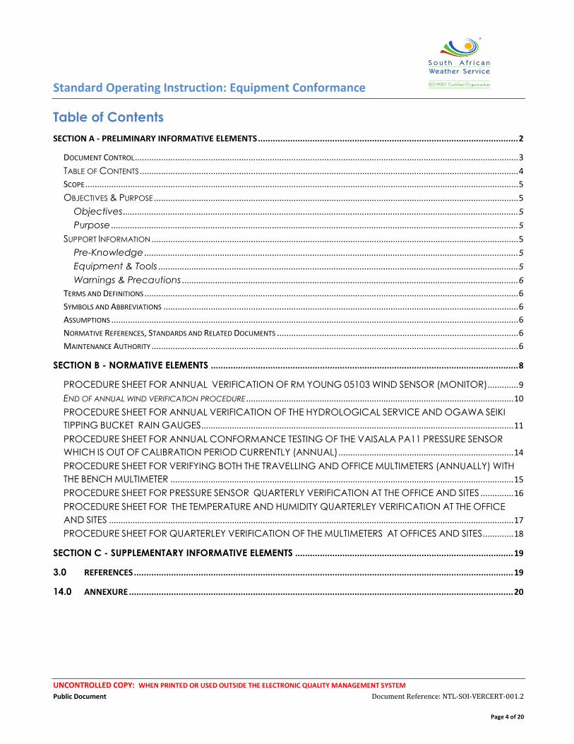
Document Control
Version and Amendment Schedule
Version Version Date Author Description of Amendments
1 28 September 2012 Riaan Lourens None
1.2 18 February 2014 Riaan Lourens Inclusion of rainfall verification and updating
the wind verification
Compliance Schedule
Compliance Type Checked
Compliance Approved by:
Responsibility Signature Date of Compliance
Approval Documentation
Compliance M. Mavimbela Manager: TQM
Legal Compliance N/A
Approval and Control Schedule
Approved By Designation Responsibility Signature Date
Approved
Copy
Status
R.B. Jardine Manager: Electronic
Maintenance and
Support
Document Owner
Master B. Shandu Senior Manager:
Technical Service
Process Owner
Standard Operating Instruction: Equipment Conformance
UNCONTROLLED COPY: WHEN PRINTED OR USED OUTSIDE THE ELECTRONIC QUALITY MANAGEMENT SYSTEM
Public Document Document Reference: NTL-SOI-VERCERT-001.2
Page 4 of 20
Table of Contents
SECTION A - PRELIMINARY INFORMATIVE ELEMENTS ......................................................................................................... 2
DOCUMENT CONTROL .................................................................................................................................................................. 3
TABLE OF CONTENTS ................................................................................................................................................................ 4
SCOPE ....................................................................................................................................................................................... 5
OBJECTIVES & PURPOSE .......................................................................................................................................................... 5
Objectives ....................................................................................................................................................................... 5
Purpose ............................................................................................................................................................................ 5
SUPPORT INFORMATION ........................................................................................................................................................... 5
Pre-Knowledge .............................................................................................................................................................. 5
Equipment & Tools ........................................................................................................................................................ 5
Warnings & Precautions .............................................................................................................................................. 6
TERMS AND DEFINITIONS .............................................................................................................................................................. 6
SYMBOLS AND ABBREVIATIONS ...................................................................................................................................................... 6
ASSUMPTIONS ............................................................................................................................................................................ 6
NORMATIVE REFERENCES, STANDARDS AND RELATED DOCUMENTS ...................................................................................................... 6
MAINTENANCE AUTHORITY ........................................................................................................................................................... 6
SECTION B - NORMATIVE ELEMENTS ............................................................................................................................ 8
PROCEDURE SHEET FOR ANNUAL VERIFICATION OF RM YOUNG 05103 WIND SENSOR (MONITOR) ............. 9
END OF ANNUAL WIND VERIFICATION PROCEDURE ................................................................................................................. 10
PROCEDURE SHEET FOR ANNUAL VERIFICATION OF THE HYDROLOGICAL SERVICE AND OGAWA SEIKI
TIPPING BUCKET RAIN GAUGES .................................................................................................................................... 11
PROCEDURE SHEET FOR ANNUAL CONFORMANCE TESTING OF THE VAISALA PA11 PRESSURE SENSOR
WHICH IS OUT OF CALIBRATION PERIOD CURRENTLY (ANNUAL) .......................................................................... 14
PROCEDURE SHEET FOR VERIFYING BOTH THE TRAVELLING AND OFFICE MULTIMETERS (ANNUALLY) WITH
THE BENCH MULTIMETER ................................................................................................................................................. 15
PROCEDURE SHEET FOR PRESSURE SENSOR QUARTERLY VERIFICATION AT THE OFFICE AND SITES .............. 16
PROCEDURE SHEET FOR THE TEMPERATURE AND HUMIDITY QUARTERLEY VERIFICATION AT THE OFFICE
AND SITES ........................................................................................................................................................................... 17
PROCEDURE SHEET FOR QUARTERLEY VERIFICATION OF THE MULTIMETERS AT OFFICES AND SITES ............. 18
SECTION C - SUPPLEMENTARY INFORMATIVE ELEMENTS ........................................................................................ 19
3.0 REFERENCES ......................................................................................................................................................... 19
14.0 ANNEXURE ........................................................................................................................................................... 20
Standard Operating Instruction: Equipment Conformance
UNCONTROLLED COPY: WHEN PRINTED OR USED OUTSIDE THE ELECTRONIC QUALITY MANAGEMENT SYSTEM
Public Document Document Reference: NTL-SOI-VERCERT-001.2
Page 5 of 20
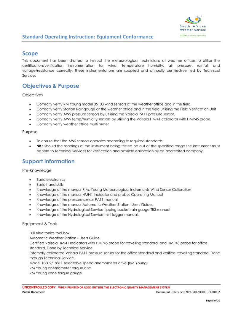
Scope
This document has been drafted to instruct the meteorological technicians at weather offices to utilise the
certification/verification instrumentation for wind, temperature humidity, air pressure, rainfall and
voltage/resistance correctly. These instrumentations are supplied and annually certified/verified by Technical
Service.
Objectives & Purpose
Objectives
Correctly verify RM Young model 05103 wind sensors at the weather office and in the field.
Correctly verify Station Raingauge at the weather office and in the field utilising the Field Verification Unit
Correctly verify AWS pressure sensors by utilising the Vaisala PA11 pressure sensor.
Correctly verify AWS temp/humidity sensors by utilising the Vaisala HMI41 calibrator with HMP45 probe
Correctly verify weather office multi meter
Purpose
To ensure that the AWS sensors operates according to required standards.
NB.: Should the readings of the instrument being tested be out of the specified range the instrument must
be sent to Technical Services for verification and possible calibration by an accredited company.
Support Information
Pre-Knowledge
Basic electronics
Basic hand skills
Knowledge of the manual R.M. Young Meteorological Instruments Wind Sensor Calibration
Knowledge of the manual HMI41 Indicator and probes Operating Manual
Knowledge of the pressure sensor PA11 manual
Knowledge of the manual Automatic Weather Station- Users Guide.
Knowledge of the Hydrological Service tipping bucket rain gauge TB3 manual
Knowledge of the Hydrological Service mini logger manual.
Equipment & Tools
Full electronics tool box
Automatic Weather Station - Users Guide.
Certified Vaisala HMI41 Indicators with HMP45 probe for travelling standard, and HMP48 probe for office
standard. Done by Technical Service.
Externally calibrated Vaisala PA11 pressure sensor for the office standard and verified travelling standard. Done
through Technical Service.
Model 18802/18811 selectable speed anemometer drive (RM Young)
RM Young anemometer torque disc
RM Young vane torque gauge
Standard Operating Instruction: Equipment Conformance
UNCONTROLLED COPY: WHEN PRINTED OR USED OUTSIDE THE ELECTRONIC QUALITY MANAGEMENT SYSTEM
Public Document Document Reference: NTL-SOI-VERCERT-001.2
Page 6 of 20
Previously certified RM Young model 05103 wind monitors
Weather office laptop computer
Hydrological Service field calibration kit and mini data logger
Warnings & Precautions
Protocols
Terms and Definitions Weather Station – means
Rainfall station
AWS Stations
Weather Offices
ARS station
Symbols and Abbreviations AWS Automatic Weather Station
ARS Automatic Rain Station
MetCap Meteorological Data Capturing System
SA South Africa
WO Weather Office
WMO World Meteorological Organisation
TS Technical Service
Assumptions That the person doing the verification of the aforementioned instrumentation has been trained in their
operation, understands the function of the different sensors, and the operation of the verification
instrumentation.
Normative References, Standards and Related Documents
WMO Regulation – CIMO IX
Maintenance Authority
Document Content
Standard Operating Instruction: Equipment Conformance
UNCONTROLLED COPY: WHEN PRINTED OR USED OUTSIDE THE ELECTRONIC QUALITY MANAGEMENT SYSTEM
Public Document Document Reference: NTL-SOI-VERCERT-001.2
Page 7 of 20
The content of this document shall be maintained by the Training Technician: Electronic
Maintenance and Support
Document Structure
The structure of this document shall be maintained by the Management Quality Representative
Standard Operating Instruction: Equipment Conformance
UNCONTROLLED COPY: WHEN PRINTED OR USED OUTSIDE THE ELECTRONIC QUALITY MANAGEMENT SYSTEM
Public Document Document Reference: NTL-SOI-VERCERT-001.2
Page 8 of 20
SECTION B - Normative Elements
Standard Operating Instruction: Equipment Conformance
UNCONTROLLED COPY: WHEN PRINTED OR USED OUTSIDE THE ELECTRONIC QUALITY MANAGEMENT SYSTEM
Public Document Document Reference: NTL-SOI-VERCERT-001.2
Page 9 of 20
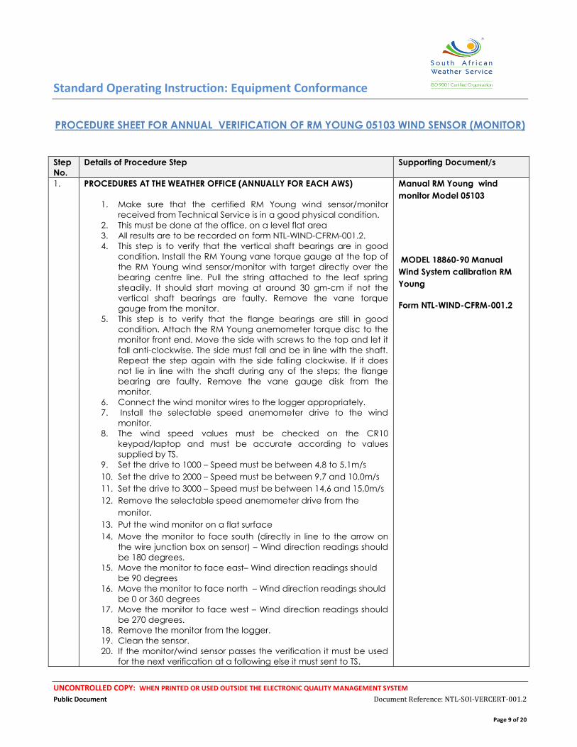
PROCEDURE SHEET FOR ANNUAL VERIFICATION OF RM YOUNG 05103 WIND SENSOR (MONITOR)
Step
No.
Details of Procedure Step Supporting Document/s
1. PROCEDURES AT THE WEATHER OFFICE (ANNUALLY FOR EACH AWS)
1. Make sure that the certified RM Young wind sensor/monitor
received from Technical Service is in a good physical condition.
2. This must be done at the office, on a level flat area
3. All results are to be recorded on form NTL-WIND-CFRM-001.2.
4. This step is to verify that the vertical shaft bearings are in good
condition. Install the RM Young vane torque gauge at the top of
the RM Young wind sensor/monitor with target directly over the
bearing centre line. Pull the string attached to the leaf spring
steadily. It should start moving at around 30 gm-cm if not the
vertical shaft bearings are faulty. Remove the vane torque
gauge from the monitor.
5. This step is to verify that the flange bearings are still in good
condition. Attach the RM Young anemometer torque disc to the
monitor front end. Move the side with screws to the top and let it
fall anti-clockwise. The side must fall and be in line with the shaft.
Repeat the step again with the side falling clockwise. If it does
not lie in line with the shaft during any of the steps; the flange
bearing are faulty. Remove the vane gauge disk from the
monitor.
6. Connect the wind monitor wires to the logger appropriately.
7. Install the selectable speed anemometer drive to the wind
monitor.
8. The wind speed values must be checked on the CR10
keypad/laptop and must be accurate according to values
supplied by TS.
9. Set the drive to 1000 – Speed must be between 4,8 to 5,1m/s
10. Set the drive to 2000 – Speed must be between 9,7 and 10,0m/s
11. Set the drive to 3000 – Speed must be between 14,6 and 15,0m/s
12. Remove the selectable speed anemometer drive from the
monitor.
13. Put the wind monitor on a flat surface
14. Move the monitor to face south (directly in line to the arrow on
the wire junction box on sensor) – Wind direction readings should
be 180 degrees.
15. Move the monitor to face east– Wind direction readings should
be 90 degrees
16. Move the monitor to face north – Wind direction readings should
be 0 or 360 degrees
17. Move the monitor to face west – Wind direction readings should
be 270 degrees.
18. Remove the monitor from the logger.
19. Clean the sensor.
20. If the monitor/wind sensor passes the verification it must be used
for the next verification at a following else it must sent to TS.
Manual RM Young wind
monitor Model 05103
MODEL 18860-90 Manual
Wind System calibration RM
Young
Form NTL-WIND-CFRM-001.2
Standard Operating Instruction: Equipment Conformance
UNCONTROLLED COPY: WHEN PRINTED OR USED OUTSIDE THE ELECTRONIC QUALITY MANAGEMENT SYSTEM
Public Document Document Reference: NTL-SOI-VERCERT-001.2
Page 10 of 20
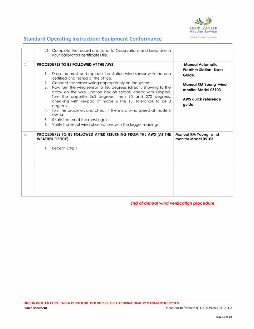
21. Complete the record and send to Observations and keep one in
your calibrators certificates file.
2. PROCEDURES TO BE FOLLOWED AT THE AWS
1. Drop the mast and replace the station wind sensor with the one
certified and tested at the office.
2. Connect the sensor wiring appropriately on the system.
3. Now turn the wind sensor to 180 degrees (directly showing to the
arrow on the wire junction box on sensor) check with keypad.
Turn the opposite 360 degrees, then 90 and 270 degrees,
checking with keypad at mode 6 line 13. Tolerance to be 3
degrees
4. Turn the propeller, and check if there is a wind speed at mode 6
line 14.
5. If satisfied erect the mast again. 6. Verify the visual wind observations with the logger readings.
Manual Automatic
Weather Station- Users
Guide.
Manual RM Young wind
monitor Model 05103
AWS quick reference
guide
3. PROCEDURES TO BE FOLLOWED AFTER RETURNING FROM THE AWS (AT THE
WEATHER OFFICE)
1. Repeat Step 1
Manual RM Young wind
monitor Model 05103
End of annual wind verification procedure
Standard Operating Instruction: Equipment Conformance
UNCONTROLLED COPY: WHEN PRINTED OR USED OUTSIDE THE ELECTRONIC QUALITY MANAGEMENT SYSTEM
Public Document Document Reference: NTL-SOI-VERCERT-001.2
Page 11 of 20
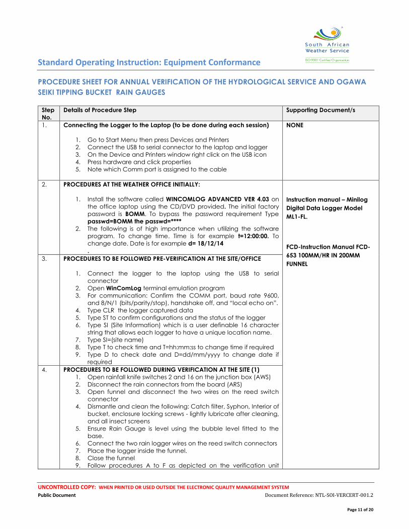
PROCEDURE SHEET FOR ANNUAL VERIFICATION OF THE HYDROLOGICAL SERVICE AND OGAWA
SEIKI TIPPING BUCKET RAIN GAUGES
Step
No.
Details of Procedure Step Supporting Document/s
1. Connecting the Logger to the Laptop (to be done during each session)
1. Go to Start Menu then press Devices and Printers
2. Connect the USB to serial connector to the laptop and logger
3. On the Device and Printers window right click on the USB icon
4. Press hardware and click properties
5. Note which Comm port is assigned to the cable
NONE
2. PROCEDURES AT THE WEATHER OFFICE INITIALLY:
1. Install the software called WINCOMLOG ADVANCED VER 4.03 on
the office laptop using the CD/DVD provided. The initial factory
password is BOMM. To bypass the password requirement Type
passwd=BOMM the passwd=****
2. The following is of high importance when utilizing the software
program. To change time. Time is for example t=12:00:00. To
change date. Date is for example d= 18/12/14
.
Instruction manual – Minilog
Digital Data Logger Model
ML1-FL.
FCD-Instruction Manual FCD-
653 100MM/HR IN 200MM
FUNNEL
3. PROCEDURES TO BE FOLLOWED PRE-VERIFICATION AT THE SITE/OFFICE
1. Connect the logger to the laptop using the USB to serial
connector
2. Open WinComLog terminal emulation program
3. For communication: Confirm the COMM port, baud rate 9600,
and 8/N/1 (bits/parity/stop), handshake off, and “local echo on”.
4. Type CLR the logger captured data
5. Type ST to confirm configurations and the status of the logger
6. Type SI (Site Information) which is a user definable 16 character
string that allows each logger to have a unique location name.
7. Type SI=(site name)
8. Type T to check time and T=hh:mm:ss to change time if required
9. Type D to check date and D=dd/mm/yyyy to change date if
required
4. PROCEDURES TO BE FOLLOWED DURING VERIFICATION AT THE SITE (1)
1. Open rainfall knife switches 2 and 16 on the junction box (AWS)
2. Disconnect the rain connectors from the board (ARS)
3. Open funnel and disconnect the two wires on the reed switch
connector
4. Dismantle and clean the following: Catch filter, Syphon, Interior of
bucket, enclosure locking screws - lightly lubricate after cleaning,
and all insect screens
5. Ensure Rain Gauge is level using the bubble level fitted to the
base.
6. Connect the two rain logger wires on the reed switch connectors
7. Place the logger inside the funnel.
8. Close the funnel
9. Follow procedures A to F as depicted on the verification unit
Standard Operating Instruction: Equipment Conformance
UNCONTROLLED COPY: WHEN PRINTED OR USED OUTSIDE THE ELECTRONIC QUALITY MANAGEMENT SYSTEM
Public Document Document Reference: NTL-SOI-VERCERT-001.2
Page 12 of 20
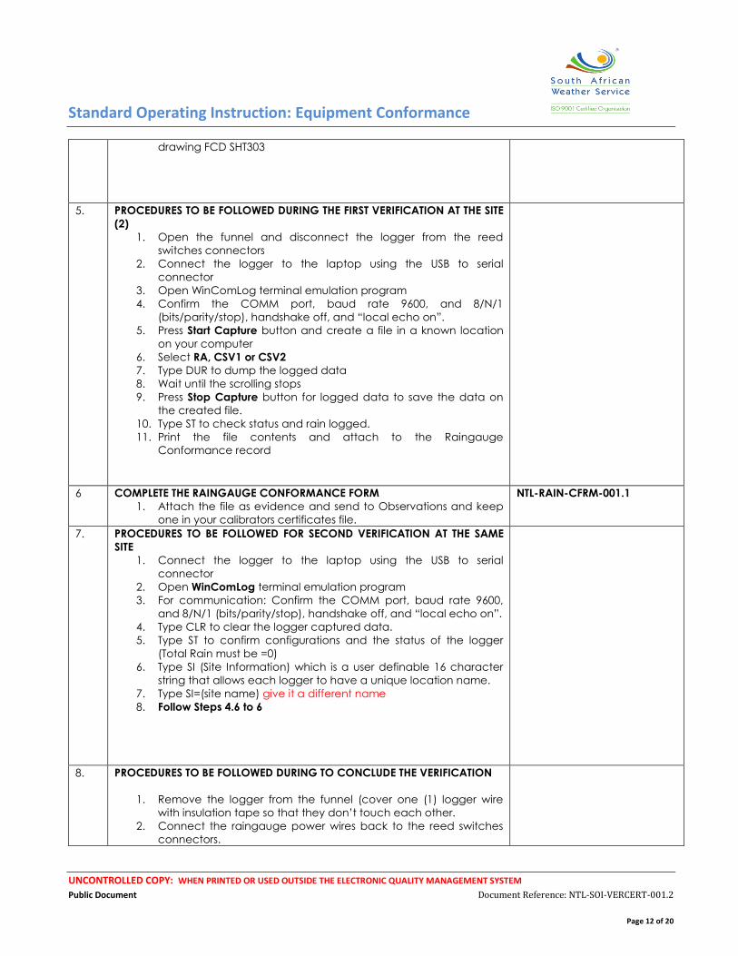
drawing FCD SHT303
5. PROCEDURES TO BE FOLLOWED DURING THE FIRST VERIFICATION AT THE SITE
(2)
1. Open the funnel and disconnect the logger from the reed
switches connectors
2. Connect the logger to the laptop using the USB to serial
connector
3. Open WinComLog terminal emulation program
4. Confirm the COMM port, baud rate 9600, and 8/N/1
(bits/parity/stop), handshake off, and “local echo on”.
5. Press Start Capture button and create a file in a known location
on your computer
6. Select RA, CSV1 or CSV2
7. Type DUR to dump the logged data
8. Wait until the scrolling stops
9. Press Stop Capture button for logged data to save the data on
the created file.
10. Type ST to check status and rain logged.
11. Print the file contents and attach to the Raingauge
Conformance record
6 COMPLETE THE RAINGAUGE CONFORMANCE FORM
1. Attach the file as evidence and send to Observations and keep
one in your calibrators certificates file.
NTL-RAIN-CFRM-001.1
7. PROCEDURES TO BE FOLLOWED FOR SECOND VERIFICATION AT THE SAME
SITE
1. Connect the logger to the laptop using the USB to serial
connector
2. Open WinComLog terminal emulation program
3. For communication: Confirm the COMM port, baud rate 9600,
and 8/N/1 (bits/parity/stop), handshake off, and “local echo on”.
4. Type CLR to clear the logger captured data.
5. Type ST to confirm configurations and the status of the logger
(Total Rain must be =0)
6. Type SI (Site Information) which is a user definable 16 character
string that allows each logger to have a unique location name.
7. Type SI=(site name) give it a different name
8. Follow Steps 4.6 to 6
8. PROCEDURES TO BE FOLLOWED DURING TO CONCLUDE THE VERIFICATION
1. Remove the logger from the funnel (cover one (1) logger wire
with insulation tape so that they don’t touch each other.
2. Connect the raingauge power wires back to the reed switches
connectors.
Standard Operating Instruction: Equipment Conformance
UNCONTROLLED COPY: WHEN PRINTED OR USED OUTSIDE THE ELECTRONIC QUALITY MANAGEMENT SYSTEM
Public Document Document Reference: NTL-SOI-VERCERT-001.2
Page 13 of 20
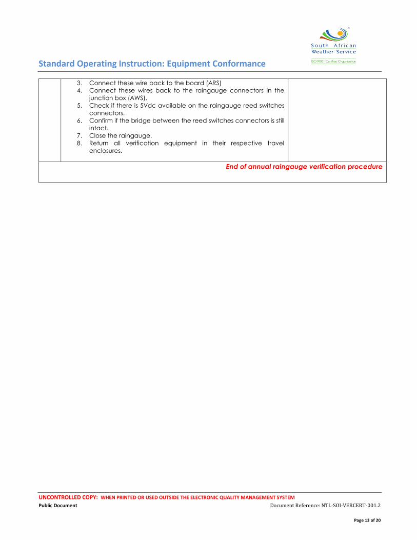
3. Connect these wire back to the board (ARS)
4. Connect these wires back to the raingauge connectors in the
junction box (AWS).
5. Check if there is 5Vdc available on the raingauge reed switches
connectors.
6. Confirm if the bridge between the reed switches connectors is still
intact.
7. Close the raingauge.
8. Return all verification equipment in their respective travel
enclosures.
End of annual raingauge verification procedure
Standard Operating Instruction: Equipment Conformance
UNCONTROLLED COPY: WHEN PRINTED OR USED OUTSIDE THE ELECTRONIC QUALITY MANAGEMENT SYSTEM
Public Document Document Reference: NTL-SOI-VERCERT-001.2
Page 14 of 20
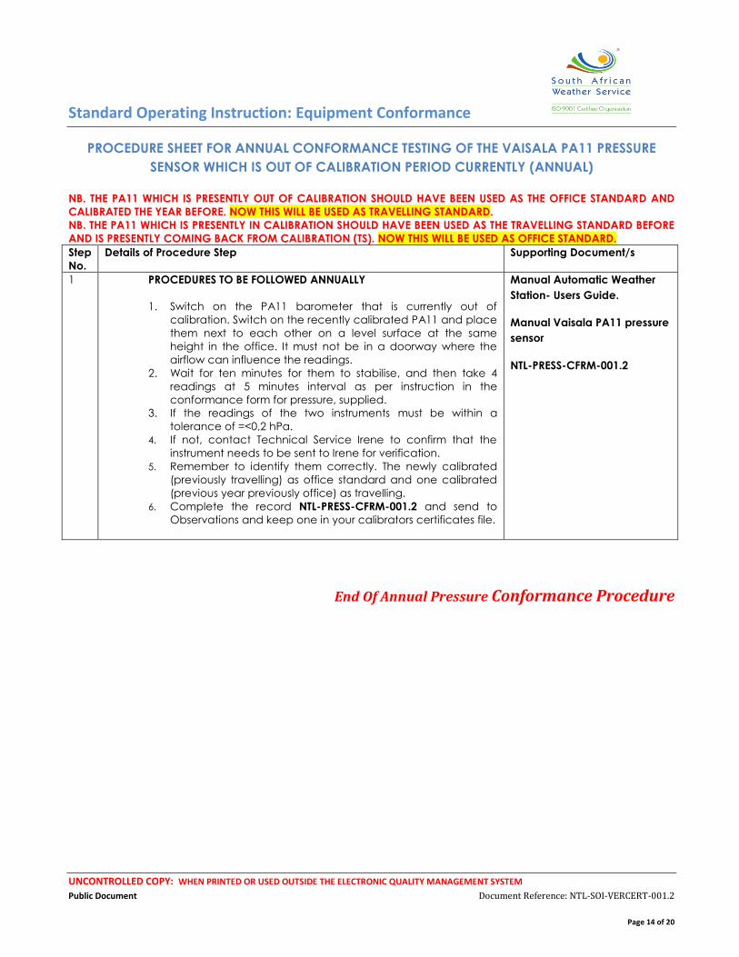
PROCEDURE SHEET FOR ANNUAL CONFORMANCE TESTING OF THE VAISALA PA11 PRESSURE
SENSOR WHICH IS OUT OF CALIBRATION PERIOD CURRENTLY (ANNUAL)
NB. THE PA11 WHICH IS PRESENTLY OUT OF CALIBRATION SHOULD HAVE BEEN USED AS THE OFFICE STANDARD AND
CALIBRATED THE YEAR BEFORE. NOW THIS WILL BE USED AS TRAVELLING STANDARD.
NB. THE PA11 WHICH IS PRESENTLY IN CALIBRATION SHOULD HAVE BEEN USED AS THE TRAVELLING STANDARD BEFORE
AND IS PRESENTLY COMING BACK FROM CALIBRATION (TS). NOW THIS WILL BE USED AS OFFICE STANDARD. Step
No.
Details of Procedure Step Supporting Document/s
1 PROCEDURES TO BE FOLLOWED ANNUALLY
1. Switch on the PA11 barometer that is currently out of
calibration. Switch on the recently calibrated PA11 and place
them next to each other on a level surface at the same
height in the office. It must not be in a doorway where the
airflow can influence the readings.
2. Wait for ten minutes for them to stabilise, and then take 4
readings at 5 minutes interval as per instruction in the
conformance form for pressure, supplied.
3. If the readings of the two instruments must be within a
tolerance of =<0,2 hPa.
4. If not, contact Technical Service Irene to confirm that the
instrument needs to be sent to Irene for verification.
5. Remember to identify them correctly. The newly calibrated
(previously travelling) as office standard and one calibrated
(previous year previously office) as travelling.
6. Complete the record NTL-PRESS-CFRM-001.2 and send to
Observations and keep one in your calibrators certificates file.
Manual Automatic Weather
Station- Users Guide.
Manual Vaisala PA11 pressure
sensor
NTL-PRESS-CFRM-001.2
End Of Annual Pressure Conformance Procedure

Standard Operating Instruction: Equipment Conformance
UNCONTROLLED COPY: WHEN PRINTED OR USED OUTSIDE THE ELECTRONIC QUALITY MANAGEMENT SYSTEM
Public Document Document Reference: NTL-SOI-VERCERT-001.2
Page 15 of 20
PROCEDURE SHEET FOR VERIFYING BOTH THE TRAVELLING AND OFFICE MULTIMETERS (ANNUALLY)
WITH THE BENCH MULTIMETER
Step
No.
Details of Procedure Step Supporting Document/s
1.
PROCEDURES AT THE WEATHER OFFICE: ANNUALLY
1. Use the externally calibrated multimeter to verify the travel or
office standard multimeter.
2. Get a known power source and verify the voltage with a
calibrated standard. Get the highest and lowest available
Voltage. (230Vac, 12Vdc and 5Vdc)
3. Verify the source with the travel/office standard (tolerance 0,5
voltage).
4. Get a known resistance source (different known resistors) and
verify with the calibrated standard.
5. Verify with the travel/office standards (tolerance 3%).
6. Complete the relevant forms NTL-MULT-CFRM-001.1 and send to
Observations and keep one in your calibrators certificates file.
NTL-MULT-CFRM-001.1
End Of Annual Multimeter Conformance Procedure

Standard Operating Instruction: Equipment Conformance
UNCONTROLLED COPY: WHEN PRINTED OR USED OUTSIDE THE ELECTRONIC QUALITY MANAGEMENT SYSTEM
Public Document Document Reference: NTL-SOI-VERCERT-001.2
Page 16 of 20
PROCEDURE SHEET FOR PRESSURE SENSOR QUARTERLY VERIFICATION AT THE OFFICE AND SITES
Step
No.
Details of Procedure Step Supporting Document/s
1. PROCEDURES AT THE WEATHER OFFICE: PRE-INSPECTION
THIS MUST BE DONE IN CONJUNCTION WITH RECORD (NTL-AWS-INSPFRM-
001.3)
1. Before leaving the weather office; the travelling standard PA11
must be verified against the office standard. The office standard
must stay in the office, and not utilised in the field
2. The pressure standards must be in a well ventilated room without
air conditioning, and must be switched on for at least 20 minutes
before a reading is taken.
3. Take both readings at five (5) minutes intervals.
4. Difference between two sensors not to be more than 0.3Hpa.
Automatic Weather Station-
Users Guide.
Manual Vaisala PA11 pressure
sensor
NTL-AWS-INSPFRM-001.3
2. PROCEDURES TO BE FOLLOWED AT THE AWS
1. Place the PA11 next to the control box (same height)
2. The PA11 must be switched on for at least 20 minutes before a
reading is taken. The outlet pipes of the sensors must be kept
away from strong wind blowing into it as much as possible.
3. Take pressure loggers and PA11 readings simultaneously at five
(5) minutes intervals.
Manual Vaisala PA11 pressure
sensor
3. PROCEDURES TO BE FOLLOWED AFTER RETURNING FROM THE AWS (AT THE
WEATHER OFFICE): POST- INSPECTION
1. The travelling standard PA11 must be compared to the office
standard after returning from the field.
2. Repeat Step 1
Manual Vaisala PA11 pressure
sensor
End Of Quarterly Pressure Verification Procedure
Standard Operating Instruction: Equipment Conformance
UNCONTROLLED COPY: WHEN PRINTED OR USED OUTSIDE THE ELECTRONIC QUALITY MANAGEMENT SYSTEM
Public Document Document Reference: NTL-SOI-VERCERT-001.2
Page 17 of 20
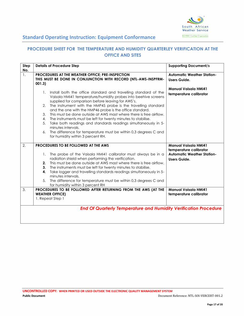
PROCEDURE SHEET FOR THE TEMPERATURE AND HUMIDITY QUARTERLEY VERIFICATION AT THE
OFFICE AND SITES
Step
No.
Details of Procedure Step Supporting Document/s
1. PROCEDURES AT THE WEATHER OFFICE; PRE-INSPECTION
THIS MUST BE DONE IN CONJUNCTION WITH RECORD (NTL-AWS-INSPFRM-
001.3)
1. Install both the office standard and travelling standard of the
Vaisala HMI41 temperature/humidity probes into beehive screens
supplied for comparison before leaving for AWS’s.
2. The instrument with the HMP45 probe is the travelling standard
and the one with the HMP46 probe is the office standard.
3. This must be done outside at AWS mast where there is free airflow.
4. The instruments must be left for twenty minutes to stabilise.
5. Take both readings and standards readings simultaneously in 5-
minutes intervals.
6. The difference for temperature must be within 0,3 degrees C and
for humidity within 3 percent RH.
Automatic Weather Station-
Users Guide.
Manual Vaisala HMI41
temperature calibrator
2. PROCEDURES TO BE FOLLOWED AT THE AWS
1. The probe of the Vaisala HMI41 calibrator must always be in a
radiation shield when performing the verification.
2. This must be done outside at AWS mast where there is free airflow.
3. The instruments must be left for twenty minutes to stabilise.
4. Take logger and travelling standards readings simultaneously in 5-
minutes intervals.
5. The difference for temperature must be within 0,3 degrees C and
for humidity within 3 percent RH
Manual Vaisala HMI41
temperature calibrator
Automatic Weather Station-
Users Guide.
3. PROCEDURES TO BE FOLLOWED AFTER RETURNING FROM THE AWS (AT THE
WEATHER OFFICE)
1. Repeat Step 1
Manual Vaisala HMI41
temperature calibrator
End Of Quarterly Temperature and Humidity Verification Procedure
Standard Operating Instruction: Equipment Conformance
UNCONTROLLED COPY: WHEN PRINTED OR USED OUTSIDE THE ELECTRONIC QUALITY MANAGEMENT SYSTEM
Public Document Document Reference: NTL-SOI-VERCERT-001.2
Page 18 of 20
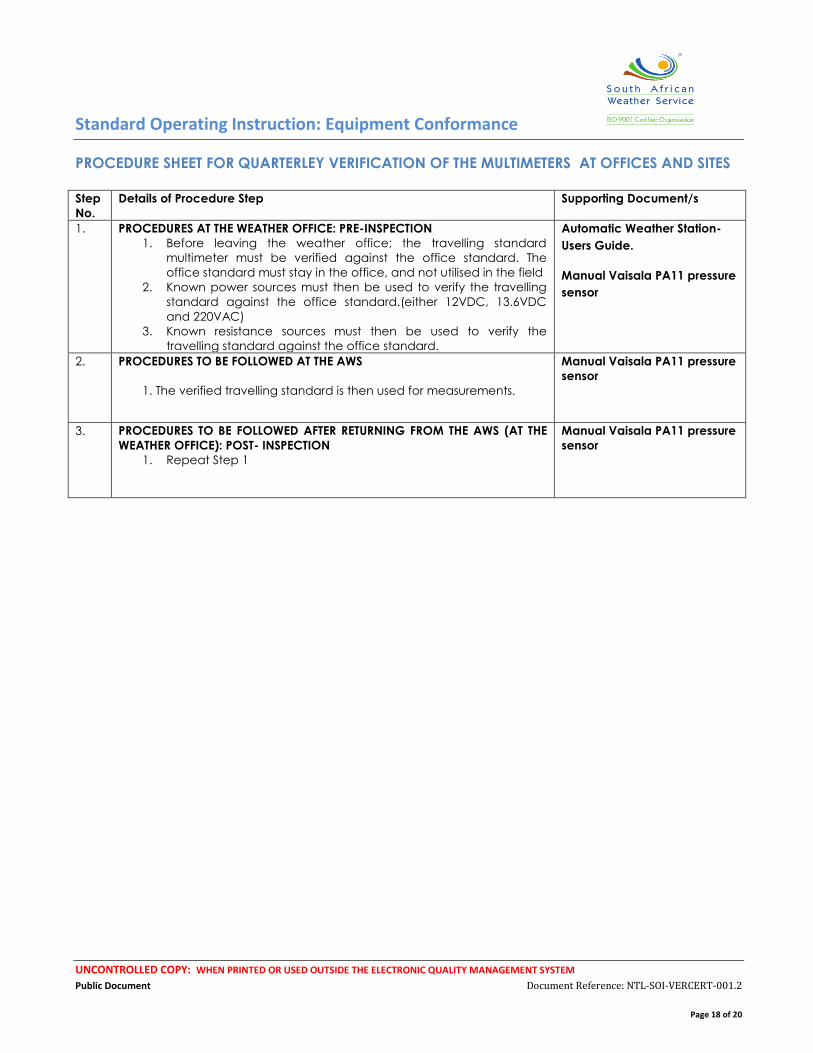
PROCEDURE SHEET FOR QUARTERLEY VERIFICATION OF THE MULTIMETERS AT OFFICES AND SITES
Step
No.
Details of Procedure Step Supporting Document/s
1. PROCEDURES AT THE WEATHER OFFICE: PRE-INSPECTION
1. Before leaving the weather office; the travelling standard
multimeter must be verified against the office standard. The
office standard must stay in the office, and not utilised in the field
2. Known power sources must then be used to verify the travelling
standard against the office standard.(either 12VDC, 13.6VDC
and 220VAC)
3. Known resistance sources must then be used to verify the
travelling standard against the office standard.
Automatic Weather Station-
Users Guide.
Manual Vaisala PA11 pressure
sensor
2. PROCEDURES TO BE FOLLOWED AT THE AWS
1. The verified travelling standard is then used for measurements.
Manual Vaisala PA11 pressure
sensor
3. PROCEDURES TO BE FOLLOWED AFTER RETURNING FROM THE AWS (AT THE
WEATHER OFFICE): POST- INSPECTION
1. Repeat Step 1
Manual Vaisala PA11 pressure
sensor
Standard Operating Instruction: Equipment Conformance
UNCONTROLLED COPY: WHEN PRINTED OR USED OUTSIDE THE ELECTRONIC QUALITY MANAGEMENT SYSTEM
Public Document Document Reference: NTL-SOI-VERCERT-001.2
Page 19 of 20
SECTION C - Supplementary Informative Elements
3.0 References
Knowledge of the manual R.M. Young Meteorological Instruments Wind Sensor Calibration
Standard Operating Instruction: Equipment Conformance
UNCONTROLLED COPY: WHEN PRINTED OR USED OUTSIDE THE ELECTRONIC QUALITY MANAGEMENT SYSTEM
Public Document Document Reference: NTL-SOI-VERCERT-001.2
Page 20 of 20
Knowledge of the manual HMI41 Indicator and probes Operating Manual
Knowledge of the pressure sensor PA11 manual
Knowledge of the manual Automatic Weather Station- Users Guide.
14.0 Annexure
None
End of Document