standard operating procedures for: installation, operation
TRANSCRIPT
1
Ozarks Environmental and Water Resources Institute (OEWRI)
Missouri State University (MSU)
Standard Operating Procedures for:
Installation, Operation, and Maintenance of the Solinst
Levelogger Gold and Barologger Gold (Model 3001)
Author
Project Supervisor
Director
Date
Date
Date

2
TABLE OF CONTENTS
TABLE OF CONTENTS ................................................................................................................ 2
LIST OF FIGURES ........................................................................................................................ 3 1.0 INTRODUCTION .................................................................................................................. 4
1.1 Scope of the method............................................................................................................ 4 1.1.1 Method ........................................................................................................................ 4
1.1.2 Purpose ........................................................................................................................ 4 1.2 Definitions........................................................................................................................... 4
2.0 EQUIPMENT AND SUPPLIES ............................................................................................. 4 2.1 Installation Checklist .......................................................................................................... 4
3.0 INSTALLATION ................................................................................................................... 5 3.1 Site Location ....................................................................................................................... 5 3.2 Pipe Installation .................................................................................................................. 5 3.3 Instrument Installation ........................................................................................................ 5
3.3.1 Introduction ................................................................................................................. 5 3.3.2 Free Suspension/Rope Installations ............................................................................ 5 3.3.3 Barologger Installation................................................................................................ 7 3.3.4 Extreme Temperature Conditions ............................................................................... 7
4.0 PRE-DEPLOYMENT ............................................................................................................. 7 4.1 Software .............................................................................................................................. 7 4.2 USB Installation .................................................................................................................. 8 4.3 Firmware ............................................................................................................................. 8 4.4 Startup, Configurations and Settings .................................................................................. 8
4.4.1 Startup ......................................................................................................................... 8 4.4.2 Communication Port Settings ..................................................................................... 9 4.4.3 Com Port Designation Set Up: .................................................................................... 9 4.4.4 Data Directory ............................................................................................................. 9
4.4.5 Levelogger Settings .................................................................................................... 9 4.4.6 Program Levelogger Settings .................................................................................... 11 4.4.7 Starting and Stopping the Levelogger ....................................................................... 11 4.4.8 Saving and Retrieving Levelogger Settings Files ..................................................... 11
5.0 DATA COLLECTION ......................................................................................................... 11 5.1 Downloading Options ....................................................................................................... 12 5.2 Graph Manipulation and Zoom Function ......................................................................... 12 5.3 Data Compensation ........................................................................................................... 13
5.3.1 Barometric Compensation ........................................................................................ 13 5.3.2 Manual Data Adjustment .......................................................................................... 13 5.3.3 Density Adjustment .................................................................................................. 14 5.3.4 Barometric Efficiency ............................................................................................... 14
5.4 Real Time View Window and File Export ....................................................................... 14

3
6.0 MAINTENANCE ................................................................................................................. 15 6.1 Levelogger Maintenance ................................................................................................... 15 6.3 High suspended solids....................................................................................................... 15
6.4 Bacteriological or chemical fouling .................................................................................. 15 7.0 MAINTENANCE CHECKLIST .......................................................................................... 16 8.0 REFERENCES ..................................................................................................................... 16
LIST OF FIGURES
Figure 1. Free Suspended Installation Method .................................................................. 6
Figure 2. Levelogger Settings Window ........................................................................... 10
Figure 3. Data Control Window and Directory ................................................................ 12
Figure 4. Data Compensation Window ............................................................................ 13
Figure 5. Real-Time Video Window ............................................................................... 14

4
1.0 INTRODUCTION
1.1 Scope of the method
1.1.1 Method
This document details the procedure for installation, operation and maintenance
of the Solinst Levelogger Gold and Barologger Gold (Model 3001) series water
level sensor and datalogger.
1.1.2 Purpose
The Levelogger Gold is an absolute (non-vented) datalogger, which measures
groundwater and surface water levels and temperature. Water levels are displayed
as temperature compensated pressure readings, and can be barometrically
compensated with the aid of a Barologger Gold.
1.2 Definitions
1.2.1 Polyvinyl chloride (PVC): a common thermoplastic resin used in a variety
of products.
1.2.2 Universal Serial Bus (USB): Most widely used hardware interface for
attaching peripherals to a computer.
2.0 EQUIPMENT AND SUPPLIES
2.1 Installation Checklist
Levelogger
Barologger
Appropriate amount of 2” diameter schedule 40 PVC electrical conduit w/
elbows and couplings
PVC primer and glue
Locking well cap
Appropriate length of wire to hang instruments
Pipe brackets
Concrete screws
Concrete drill bit appropriate for screw diameter
Hammer drill

5
3.0 INSTALLATION
3.1 Site Location
The preferred site for installation is at a bridge or other structure where the pipe
can be mounted to concrete. Alternative sites may be used, but pipe housing must
be securely mounted to withstand high flows.
3.2 Pipe Installation
The PVC pipe should be mounted to concrete walls or piers using the appropriate
sized brackets and concrete screws. Several 45 and 90 degree elbows, or sweeps,
should be available if the pipe needs to be installed around corners. Couplings are
needed to attach pipe ends together when “bell” ends are not available. Pipe is
secured at all joints with PVC primer and glue.
3.3 Instrument Installation
3.3.1 Introduction
The Levelogger and Barologger are to be installed using a free suspended
installation method. For the free suspended installation method the instrument is
hung by a suspension wire or reliable string. It should be anchored on the other
end to support the weight of the unit.
Do not drop the Levelogger. The pressure transducer can be damaged. It can also
be damaged if over pressurized (150%) above its recommended range. The unit
can also be damaged by the effects of a steam hammer or hydraulic jump. Steam
hammer is caused by pressure surges and hydraulic jumps occur when
obstructions cause water to build and increase the velocity once it clears the
obstacle. This can alter the readings at the installation site. If hydraulic jump
occurs within the area care should be observed when determining the installation
location.
3.3.2 Free Suspension/Rope Installations
When installing using a suspension wire or rope, the Levelogger is
preprogrammed and started using the software. It is then deployed using a
suspension wire or rope connected to the installation cap of the Levelogger to the
underside of a well cap. The data is retrieved manually, by withdrawing the
Levelogger, removing the installation cap and attaching an Optical Reader
directly to the datalogger. Data is downloaded to a desktop or laptop PC.
Follow these steps to install the Levelogger and Barologger.
6
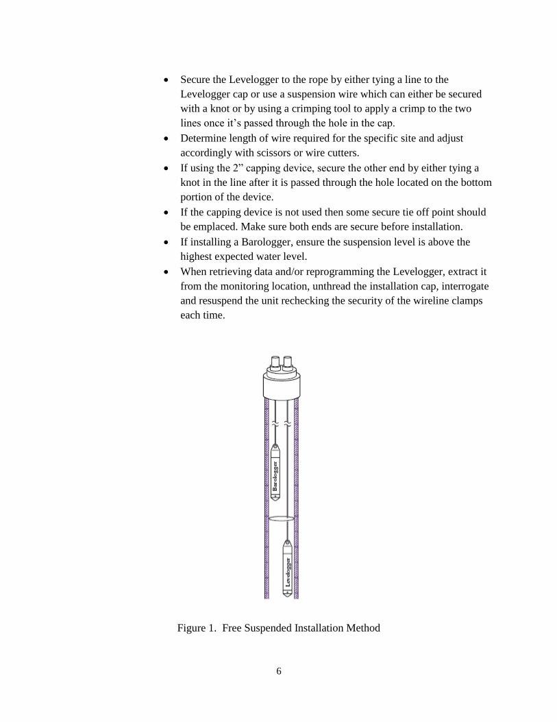
Secure the Levelogger to the rope by either tying a line to the
Levelogger cap or use a suspension wire which can either be secured
with a knot or by using a crimping tool to apply a crimp to the two
lines once it‟s passed through the hole in the cap.
Determine length of wire required for the specific site and adjust
accordingly with scissors or wire cutters.
If using the 2” capping device, secure the other end by either tying a
knot in the line after it is passed through the hole located on the bottom
portion of the device.
If the capping device is not used then some secure tie off point should
be emplaced. Make sure both ends are secure before installation.
If installing a Barologger, ensure the suspension level is above the
highest expected water level.
When retrieving data and/or reprogramming the Levelogger, extract it
from the monitoring location, unthread the installation cap, interrogate
and resuspend the unit rechecking the security of the wireline clamps
each time.
Figure 1. Free Suspended Installation Method

7
3.3.3 Barologger Installation
The Barologger measures barometric pressure. The readings can be used to
compensate Levelogger readings. The correct altitude (within 10m) must be
determined or it will result in incorrect readings. A Barologger has the ability to
compensate all Leveloggers within a 20 mile (30 km) radius. It can also be
applicable to every 1,000 ft. (300 m) in elevation.
The Barologger shouldn‟t ever be submerged. The Barologger should be
suspended above the high water point. In conditions where freezing is possible,
the Barologger should be suspended below the frost line and deep enough to
avoid large temperature fluctuations.
3.3.4 Extreme Temperature Conditions
Leveloggers can be damaged by extreme temperatures. If water freezes solid it
can damage the pressure transducer. With certain precautions, the Levelogger can
be used in these environments.
The transducer can be lowered below the frost line or ice formation depth.
In shallow areas like streams, wetlands, or ponds; install the Levelogger in
a vented stilling well imbedded into the bottom below the frost line.
If the Levelogger has to be installed in the freezing zone, place the
Levelogger inside two rubber or latex balloons. These can then be filled
with a non-toxic, non-corrosive anti-freeze solution and sealed. Place the
balloons in a section of perforated, 2” diameter schedule 40 PVC electrical
conduit and install the logger. The antifreeze solution will protect the
Levelogger from ice expansion at the pressure transducer, yet transmit any
pressure fluctuations that occur.
At the other end, exposing the Levelogger to temperatures beyond 80°C
(180°F) can damage the thermistor and alter readings.
4.0 PRE-DEPLOYMENT
4.1 Software
To install Levelogger Gold software, follow these steps:
When the Levelogger CD in inserted into the CD ROM drive the program
will automatically detect the program. Otherwise download the software
from www.solinst.com/Downloads/ and save the file.
Restart the computer after installation is completed.

8
4.2 USB Installation
Plug the USB device into the computer, and Windows will automatically detect
the connected device and start the Hardware Installation Wizard. If your device is
plugged in and the Found New Hardware Wizard fails to start, then follow these
steps:
Open the Device Manager.
Identify the Solinst device from the list.
Highlight the device in the list and right click. You will see an option to
“Update the driver”. This will start the “Hardware Update Wizard”. Now
follow the instructions for your specific Windows version.
4.3 Firmware
To upload new firmware to a Levelogger Gold, follow these steps:
Open the Solinst Firmware Update Utility (LLGfirmwareUpdate.exe),
which is located in the „Utility‟ folder in the Levelogger folder. Pick the
Com Port to which the Levelogger is connected and make sure the Baud
Rate is set to 9600.
Click the left most „Open‟ button, which should open a file dialog asking
for the firmware file (*.ssf) to upload. Navigate to the directory where the
firmware file is located then click on the file and click „Open‟.
Check the „Firmware File Information‟ box to make sure that the opened
file is the right one.
Click the „Upload Firmware‟ button, which is the second button from the
left, to start the firmware upload process.
If a communication error occurs and is indicated in the Levelogger
Information Window either before the „Verified Program Checksum‟
message or after the „Program Information Section‟, then restart the
upgrade process.
If, a communication error occurs between the „Verified Program
Checksum‟ and the „Program Information Section‟ messages, contact
Solinst.
4.4 Startup, Configurations and Settings
4.4.1 Startup
To start the Levelogger PC Software, click the icon, or click the Start button and
select: Programs > Solinst > Levelogger > Levelogger 3.4.0 (or higher).

9
4.4.2 Communication Port Settings
If using a USB port, plug in the USB cable before starting the Levelogger
Software. The Com Port Setting required for this method is RS232 or the USB
communication port, selected from the communication settings. Once the program
begins, parameters can be established using the software.
In the “Com Port Selection” field, select the communication port that is connected
to the Levelogger. The program automatically detects the available Com ports on
your computer. USB port communication requires the installation of USB driver
software and the setting up of a Virtual Com port. If using a USB port, you must
either:
Connect a Levelogger Optical Reader or PC Interface Cable to the USB
port
Use a USB to RS232 Adapter
4.4.3 Com Port Designation Set Up:
Open the Device Manager
Double Click the Ports Icon and select the „USB Serial Port‟
Right click and select Properties
Click the „Port Settings‟ tab and click „Advanced‟
Select the Com Port Number and click „OK‟
4.4.4 Data Directory
The program will save data downloaded to the following default directory:
<C:\Program Files\Solinst\Levelogger3_4\Data> unless otherwise specified in the
Default Directory field of the Application Settings Window.
4.4.5 Levelogger Settings
Click the button with the green arrow (top left) to retrieve the current settings
from a connected Levelogger.

10
Figure 2. Levelogger Settings Window
Fill in the pertinent information in the “Project ID” and “Location” fields.
Each item is limited to 32 characters.
Altitude should be specified as well in either feet or meters above sea level,
where the logger is actually deployed.
Offset should be set at “0.00” in order to keep readings relative to the tip of
the logger. Although it can be altered to reflect the distance between the tip of
the Levelogger and the monitoring well cap or static water level.
Range refers to the water fluctuation range capability of the device, measured
in meters.
The Temperature tab, was pre-programmed by Solinst in °C and cannot be
changed. Recommended range of the unit is (-20°C to 80°C).
Conductivity (Figure 3) can be determined by selecting either mS/cm or
μS/cm.
The Temperature Coefficient field shown in the conductivity tab, allows you
to choose the actual conductivity („Conductivity‟) at the current temperature
or select Specific Conductance („Spec. Cond‟.) Do not change the
measurement unless the specific values are determined of the solution in
which you are measuring.
11
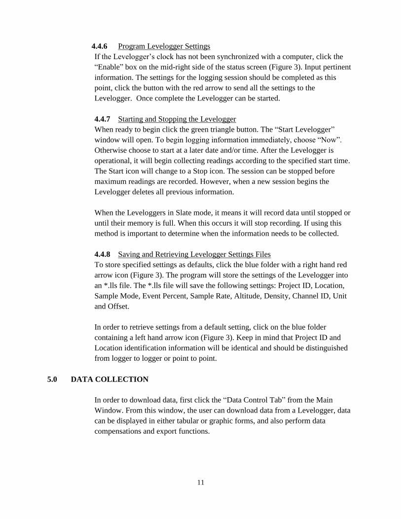
4.4.6 Program Levelogger Settings
If the Levelogger‟s clock has not been synchronized with a computer, click the
“Enable” box on the mid-right side of the status screen (Figure 3). Input pertinent
information. The settings for the logging session should be completed as this
point, click the button with the red arrow to send all the settings to the
Levelogger. Once complete the Levelogger can be started.
4.4.7 Starting and Stopping the Levelogger
When ready to begin click the green triangle button. The “Start Levelogger”
window will open. To begin logging information immediately, choose “Now”.
Otherwise choose to start at a later date and/or time. After the Levelogger is
operational, it will begin collecting readings according to the specified start time.
The Start icon will change to a Stop icon. The session can be stopped before
maximum readings are recorded. However, when a new session begins the
Levelogger deletes all previous information.
When the Leveloggers in Slate mode, it means it will record data until stopped or
until their memory is full. When this occurs it will stop recording. If using this
method is important to determine when the information needs to be collected.
4.4.8 Saving and Retrieving Levelogger Settings Files
To store specified settings as defaults, click the blue folder with a right hand red
arrow icon (Figure 3). The program will store the settings of the Levelogger into
an *.lls file. The *.lls file will save the following settings: Project ID, Location,
Sample Mode, Event Percent, Sample Rate, Altitude, Density, Channel ID, Unit
and Offset.
In order to retrieve settings from a default setting, click on the blue folder
containing a left hand arrow icon (Figure 3). Keep in mind that Project ID and
Location identification information will be identical and should be distinguished
from logger to logger or point to point.
5.0 DATA COLLECTION
In order to download data, first click the “Data Control Tab” from the Main
Window. From this window, the user can download data from a Levelogger, data
can be displayed in either tabular or graphic forms, and also perform data
compensations and export functions.

12
Figure 3. Data Control Window and Directory
5.1 Downloading Options
In order to download the information from the collection, click the blue folder
with red downward arrow on the Data Control window (Figure 4). Select “All
Data”, the program will download all the data from the current logging session of
a Levelogger as a *.lev file.
5.2 Graph Manipulation and Zoom Function
To perform the Zoom In or out on the graph, click the plus or minus buttons
(Figure 4). Multiple portions of the graph can be altered to the user‟s
specifications, such as labels, markers, etc, by clicking on the “Graph Option”.
The Channel Selection Option allows for one to define each possible channel on
the graph. Click the available options to select the required channels.

13
5.3 Data Compensation
Figure 4. Data Compensation Window
Click the Data Compensation icon to open the Data Compensation Wizard.
Identify the specific file. After the selection of the file type, click “Next” and the
Data Compensation window (Figure 5) will open. There are four compensations
to select from: Barometric Compensation, Manual Data Adjustment, Density
Adjustment and Barometric Efficiency.
5.3.1 Barometric Compensation
Requires both the Barometric file and the submerged Levelogger files. In
order to obtain a value subtract the barometric reading from the
Levelogger reading.
5.3.2 Manual Data Adjustment
Allows the user to enter a manual water level measurement as a reference
datum or field zero, which all Levelogger water level readings can then be
adjusted to. If the value is greater it can be entered as a negative value. If
the value is below water level, a positive value is recorded. The date and
time must be recorded as well. The program determines the correction
factor and adjusts all the data in the selected file.

14
5.3.3 Density Adjustment
Allows for the correction based on a user input adjustment of fluid density
ranges if known.
5.3.4 Barometric Efficiency
Is often expressed as a percentage or proportion and has a default value of
1.00. However, it can be altered from 0.01 to 3.00. Both the default and
altered settings can be saved as a*.lev file. Do not change or delete the file
extension.
5.4 Real Time View Window and File Export
In order to view the Real time information, click the Real Time View tab from the
main software window and the current readings will be provided. The results can
be displayed as a graph or in tabular format. If certain information is not required,
it can be removed by unchecking the check box to the right of the data display.
However, if it‟s not selected, the information will not be recorded. Information
recorded can be saved by exporting the data into a *.csv file, using choosing the
file export option.
To begin the current readings, click the Start icon. To record information at a
specific time, click the read now button. This reading will be added to the data set.
Figure 5. Real-Time Video Window

15
Data can be exported from the unit in a *.csv (comma separated value) file format
by clicking File> Export > Data. Which can be opened in Microsoft Excel.
6.0 MAINTENANCE
6.1 Levelogger Maintenance
Levelogger maintenance consists of cleaning the outside stainless steel casing, the
circulation holes and the optical infrared eyes. Check the unit when collecting
data. Cleaning consists of rinsing the Levelogger with a mild, non-abrasive
household cleaner and a very soft-plastic, bristled, pipe-cleaner type brush. Do not
insert any object through the circulation holes at the sensor end of the Levelogger.
A number of conditions require specific maintenance protocols. These include
conditions like hard water, high suspended solids loading, biological or chemical
fouling and salt or brackish water conditions. Also it is imperative to check to the
canister in which the unit is housed. The holes in the bottom should be free of
debris and sedimentation. Check to make sure the unit is properly secured by the
concrete anchors and is not loose.
6.2 Hard water conditions
Calcium and magnesium have the potential to deposit on the pressure transducer
as well as other components of the Levelogger. These deposits can be safely
dissolved using a diluted solution (typically ≤ 10% strength) of acetic or
phosphoric acid.
6.3 High suspended solids
High suspended solids may block the circulation ports or clog the internal
pressure cell of the Levelogger. Clogging can be minimized by placing the unit in
an area of higher flow potential. In order to remove built up solids, rinse the
Levelogger in a sink using a low water flow.
6.4 Bacteriological or chemical fouling
Bacteriological or chemical fouling can be an important consideration to take into
account with installation sites. Chemical deposits can be caused by either
electrical charge created by the unit and surrounding material, or by certain
chemical compositions. Both forms of fouling can result in difficult to remove
deposits. To remove fouling use a diluted (≤ 10%) solution of sulfuric acid.
Persistent material may require soaking for several hours.

16
7.0 MAINTENANCE CHECKLIST
Mild, non-residual, non-abrasive household cleaner.
Soft-plastic, bristled, pipe-cleaner type brush.
Acetic or Phosphoric Acid (≤ 10%) for hard water conditions.
Water to rinse suspended solids from unit.
Sulfuric Acid (≤ 10%) for Bacteriological or chemical fouling.
8.0 REFERENCES
Levelogger Series (Levelogger Gold, Barologger Gold, Levelogger Junior,
LTC Levelogger Junior and Rainlogger) User Guide – Software Version
3.4.1. (2011). Solinst, Ontario, Canada.