standard program technical description meter 250 degree .pdf · standard program technical...
TRANSCRIPT

Standard Program Technical Description
Technical Description
Square Panel Meters
Square panel meters per DIN 43700 with quadrant scale, dull black or dull gray (RAL 7037) bezel per DIN 43718. .
Interchangeable Scales Meter’s scale plate replacement is quick and simple with no
loss of accuracy and without tools. The permanently affixed closure flag at the top, or at the left side of the housing (for 144x144 mm panel meters only) need only be opened, and the scale can then be pulled out
and removed.
Terminal Connections M4 screw terminals with self-lifting terminal clips simplify clamping of connector wires. Terminal screws can be turned with crosses - head or with standard screw drivers.
Except for ammeters with direct connection: Moving - coil ammeters ≥ 6A and 40A/60A, moving - iron ammeters include M6 bolt terminals and 100A moving - iron ammeters have M8 bolt terminals.
Housings The rugged polycarbonate housing is self-extinguishing and drip-proof per UL 94 V-0. Glass faceplate material: silicate glass Bezels and glass faceplates can be easily replaced.
All panel meters are optionally available with a sheet metal housing, except for power meters and meters with front panel dimensions of 48x48 mm and 144x144 mm. Several instruments can me mounted side by side without
spacers for space saving installation.(The “polycarbonate housing with 2 leaf springs” option is required for meters with front dimensions of 48x48 mm). The hosing configuration, as well as a special housing for
panel meters with front panel dimensions of 48x48 mm (available as an option), allow for installation into the various grid systems.
Mounting All mounting fasteners are resistant to excessive vibration
and shock (order no.LN56) The S type screw clamp supplied as standard equipment can be used with polycarbonate and sheet metal housings with a control panel thickness of ≤ 25 mm, and the screw
spindle (with 144x144 mm panel meters only) for control panel thicknesses of ≤ 40 mm.
The following are available as options:
• Sheet metal housing with screw clamp per B DIN43835 for control panel thicknesses of ≤ 40 mm (except for power meters and panel meters with front
panel dimensions of 48x48 mm).
• Polycarbonate housing with front dimensions of 48x48mm
for manual grid mount, no fasteners.
• Polycarbonate housing with 2 leaf springs for standard stress requirements, also suitable for H&B Unblocks and manual grid mount for panel meters with front panel dimensions of 72x72 mm and 96x96mm
(except for power meters and meters with front panel dimensions of 144x144 mm).
• Polycarbonate housing with front panel dimensions of 48x48 mm for H&B Unblock grid with 2 leaf springs (Broncos spring).
• Polycarbonate housing with 4 leaf springs for heightened stress requirements (except for power meters and meters with front panel
dimensions of 144x144 mm).
Advantages of leaf spring mounting:
- Time saving, front mounting into DIN control panel cutout for control panel thicknesses of ≥ 1mm - Front mounting into grid systems (see above)
• Polycarbonate housing with Subtle fastener (screw clamp similar to type “S” with cup point) for Sulked
grid(except for meters with front panel dimensions of 144x144 mm).
IEC,EN and DIN Standards and VDE Regulations for Electrical Measuring Instruments Our panel meters comply with the regulations set forth in European guidelines 73/23/EWG and 89/336/EWG, which has
been substantiated by adherence to the following standards: IEC61010-1/A2/, EN61010-1/A2/ VDE0400-1/A1 (safety requirements) IEC 60051/EN 60051/DIN EN 60051 (measuring instruments
with scale display) EN 50081 – 2 : 1993 EMC (interference emission, industrial) EN 50082 – 2 : 1995 EMC (interference immunity, industrial)
The most important regulations for manufacture of electrical measuring instruments Included therein, as well as their characteristics, are defined below.
Accuracy
The accuracy of a measuring instrument or any of its accessories is determined by inherent deviation limits and influence error limits. Inherent deviation is the measurement deviation of a measuring instrument and/or any of its accessories,
when these are operated under reference conditions in accordance with DIN EN 60051. Measuring instrument influence error is the difference between two indicated values for the same measured quantity, when the individual influence variable demonstrates two different, predetermined values, one after the other, within nominal range of use in accordance with DIN 60051
Our measuring instruments comply with accuracy class 1.5 unless otherwise specified for individual measuring instrument types.
The accuracy class is indicated on the scale, for example Class 1.5 which means that the limits for inherent deviation are equal to ± 1.5% of the reference value. The reference value is generally the upper measuring range limit with the following exceptions:
• Reference value is equal to the sum of the absolute values which correspond to the upper and lower measuring range values, as long as both the electrical and the mechanical
zero points • Reference value is equal to 90 electrical degrees for power factor meters
Safety Precautions Instruments with damaged bezels or glass faceplates must be disconnected from the mains.
Adequate safety clearance must be maintained to control panel fasteners and to sheet metal housings if non-isolated (stripped) connector wires are used.
The terminal block cover must be snapped into place after the connector wires have been clamped in order to assure back of hand and finger contact safety in accordance with VBG 4.
Scales may only be replaced under voltage – free conditions.
Bezels and glass faceplates may only be replaced under voltage – free conditions.
1 Amptron Instruments (Thailand) Co., Ltd.
Standards and Regulations IEC,EN and DIN Standards and VDE Regulations for Electrical Measuring Instruments
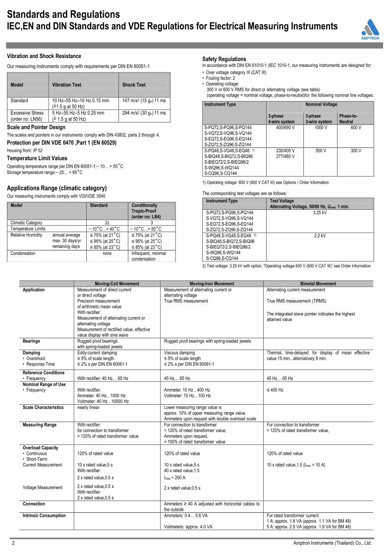
Vibration and Shock Resistance
Our measuring instruments comply with requirements per DIN EN 60051-1
Model Vibration Test Shock Test
Standard 10 Hz–55 Hz–10 Hz 0.15 mm (=1.5 g at 50 Hz)
147 m/s2 (15 gn) 11 ms
Excessive Stress
(order no: LN56)
5 Hz–55 Hz–5 Hz 0.25 mm
(= 1.5 g at 50 Hz)
294 m/s2 (30 gn) 11 ms
Scale and Pointer Design
The scales and pointers in our instruments comply with DIN 43802, parts 2 through 4.
Protection per DIN VDE 0470 ,Part 1 (EN 60529)
Housing front: IP 52
Temperature Limit Values
Operating temperature range per DIN EN 60051-1: 10… + 55˚C
Storage temperature range: 25… + 65˚C
Applications Range (climatic category)
Our measuring instruments comply with VDI/VDE 3540
Model Standard Conditionally
Tropic-Proof (order no: LB4)
Climatic Category 2z 3
Temperature Limits 10˚C…+ 40˚C 10˚C…+ 55˚C
Relative Humidity:
annual average max. 30 days/yr remaining days
≤ 75% (at 21˚C)
≤ 95% (at 25˚C)
≤ 85% (at 23˚C)
≤ 75% (at 21˚C)
≤ 95% (at 25˚C)
≤ 85% (at 23˚C)
Condensation none Infrequent, minimal condensation
Safety Regulations In accordance with DIN EN 61010-1 (IEC 1010-1, our measuring instruments are designed for:
• Over voltage category III (CAT III) • Fouling factor: 2 • Operating voltage: 300 V or 600 V RMS for direct or alternating voltage (see table) (operating voltage = nominal voltage, phase-to-neutral)for the following nominal line voltages:
Instrument Type
Nominal Voltage
3-phase 4-wire system
3-phase 3-wire system
Phase-to- Neutral
S-PQ72,S-PQ96,S-PQ144 S-VQ72,S-VQ96,S-VQ144 S-EQ72,S-EQ96,S-EQ144 S-ZQ72,S-ZQ96,S-ZQ144
400/690 V
1000 V 600 V
S-PQ48,S-VQ48,S-EQ48 1)
S-BIQ48,S-BIQ72,S-BIQ96 S-BIEQ72/2,S-BIEQ96/2 S-WQ96,S-WQ144 S-CQ96,S-CQ144
230/400 V 277/480 V
500 V 300 V
1) Operating voltage: 600 V (600 V CAT III) see Options / Order Information The corresponding test voltages are as follows:
Instrument Type Test Voltage Alternating Voltage, 50/60 Hz, Urms’ 1 min.
S-PQ72,S-PQ96,S-PQ144 S-VQ72,S-VQ96,S-VQ144 S-EQ72,S-EQ96,S-EQ144 S-ZQ72,S-ZQ96,S-ZQ144
3.25 kV
S-PQ48,S-VQ48,S-EQ48 2) S-BIQ48,S-BIQ72,S-BIQ96 S-BIEQ72/2,S-BIEQ96/2 S-WQ96,S-WQ144 S-CQ96,S-CQ144
2.2 kV
2) Test voltage: 3.25 kV with option, ”Operating voltage 600 V (600 V CAT III)” see Order Information
Moving-Coil Movement Moving-Iron Movement Bimetal Movement
Application Measurement of direct current or direct voltage Precision measurement of arithmetic mean value With rectifier: Measurement of alternating current or alternating voltage Measurement of rectified value, effective value display with sine wave
Measurement of alternating current or alternating voltage True RMS measurement
Alternating current measurement True RMS measurement (TRMS)
The integrated slave pointer indicates the highest attained value
Bearings
Rugged pivot bearings with spring-loaded jewels
Rugged pivot bearings with spring-loaded jewels
Damping • Overshoot • Response Time
Eddy-current damping ≤ 5% of scale length ≤ 2% s per DIN EN 60061-1
Viscous damping ≤ 5% of scale length ≤ 2% s per DIN EN 60061-1
Thermal, time-delayed, for display of mean effective value 15 min., alternatively 8 min.
Reference Conditions • Frequency
With rectifier: 40 Hz… 65 Hz
45 Hz… 65 Hz
45 Hz… 65 Hz
Nominal Range of Use • Frequency
With rectifier: Ammeter: 40 Hz…1000 Hz Voltmeter: 40 Hz…10000 Hz
Ammeter: 15 Hz…400 Hz Voltmeter: 15 Hz…100 Hz
≤ 400 Hz
Scale Characteristics nearly linear
Lower measuring range value is approx. 10% of upper measuring range value. Ammeters upon request with double overload scale
Measuring Range With rectifier: for connection to transformer = 120% of rated transformer value
For connection to transformer = 120% of rated transformer value, Ammeters upon request, = 100% of rated transformer value
For connection to transformer = 120% of rated transformer value,
Overload Capacity • Continuous • Short-Term: Current Measurement Voltage Measurement
120% of rated value 10 x rated value,5 s With rectifier:
2 x rated value,0.5 s
2 x rated value,0.5 s With rectifier: 2 x rated value,0.5 s
120% of rated value 10 x rated value,5 s 40 x rated value,1.5
Imax = 250 A
2 x rated value,0.5 s
120% of rated value 10 x rated value,1.5 (Imax = 10 A)
Connection
Ammeters ≥ 40 A adjusted with horizontal cables to the outside
Intrinsic Consumption Ammeters: 0.4… 0.6 VA Voltmeters: approx. 4.0 VA
For rated transformer current: 1 A: approx. 1.6 VA (approx. 1.1 VA for BM 48) 5 A: approx. 2.5 VA (approx. 1.9 VA for BM 48)
2 Amptron Instruments (Thailand) Co., Ltd.
^
^

Square Panel Meters Alternating Current 40… 45 … 65 … 1000 Hz or Alternating Voltage 40 …45 … 65 … 10000 Hz
Moving-Coil Movement with Rectifier, 250° Scale Narrow Bezel per DIN 43718
Front Dimensions 48 x 48 mm. 72 x 72 mm. 96 x 96 mm. 144 x 144 mm. Type S-EL 48-250 S-EL 72-250 S-EL 96-250 S-EL 144-250
Scale Length 37 mm. 63 mm. 97 mm. 150 mm. Accuracy Class 1.5 1.5 1.5 1.5 Weight (standard model ). Max. 0.12kg 0.2 kg. 0.28 kg. 0.49 kg. Operating Voltage. Max 300 V 600 V 600 V 600 V
Test Voltage 2.2 kV 3.25 kV 3.25 kV 3.25 kV Front Housing-Panel Protection IP 52 IP52 IP52 IP 52
In Preparation
Description
Analog Panel Meter with Core-Magnet Moving Coil Movement and Spring-Loaded Pivot Bearings and Rectifier
Type S-EL96-250
Internal Resistance / power Consumption
Measuring Input
Internal Resistance Power
Consumption
Connection
to transformer current
approx. 0.15 VA
direct or to
transformer voltage 900 Ω / V± 10%
Reference Conditions
Reference Quantities Reference Condition
Ambient Temperature
Position of Use Frequency Wave shape Other
23°C ± 2°C
control panel vertical ±1° 45 … 65 Hz sine, distortion factor ≤ 1% DIN EN 60051
Nominal Range of Use Limits
Frequency for alternating current, 40 … 1000 Hz
for automating current, 40 … 10000 Hz
Dimensions
With separate matching transformers for ammeters with front Panel dimensions of 48 x 48 mm: Lx W x H = 80 x 55 x 3.1 mm. Dimensional Drawing ( upon request ) 1303A1839HO
Dimensions
Display
Scale Graduation Pointer
Mechanical Design
Housing Material
Mounting Fasteners
Scale Replaceable
Terminals Terminal Designation
Contact Protection
Coarse-fine Beam pointer with knife-edge
Polycarbonate, self-extinguishing and drip-proof per UL94V-0 or sheet metal housing for front panel dimensions of
72 x 72 mm and 96 x 96 mm as option. Standard: S type screw clamp, except: screw spindle for 144 x 144 mm panel meters alternative : see next page
Interchangeable scales Scales may only be replaced under voltage-free conditions! Bezels and glass faceplate May only be replaced under voltage-free conditions!
M4 screw terminals with self-lifting terminal clips. Screws can be turned with cross-head or standard screw drivers. “ 11” and “12” , except: “17” and “ 18” for 144 x 144 mm panel meters
Finger-safe full cover included
Ordering Information
Model
S-EL96 Dimension 96x96 mm. Scale 250Degree Volt meter
Direct connection 0-150V, 0-300V, 0-500V ,0-600V PT connection 100, 110, 115, 120VAC Amp Meter Direct 1.2A, 6A. CT Connection 1A, 5A
Class
Class 1.5 standard or others by request
Example
1) S-EL96 Volt Meter Input PT 115kV/115V, Range 0-130kV Class 1.5, Scale 250 Degree
2) S-EL96 Amp Meter Input CT100/5A, Range 0-100A Class 1.5, Scale 250 Degree
Front in mm. Nominal Dimensions ,mm. Cutout Dimensions, mm. I1 x I2
Installation Depth Including Terminals (t). mm. M4
Installation Depth Including Full Cover (f), mm.
a1 x a2 h
48 x 48 48 x 48 5 45 + 0.6 x 45 + 0.6 54 62.5 72 x 72 72 x 72 5 68 + 0.7 x 68 + 0.7 54 62.5 96 x 96 96 x 96 5 92 + 0.8 x 92 + 0.8 54 62.5
144 x 144 144 x 144 8 138 + 1 x 138 + 1 54 62.5
10 Amptron Instruments (Thailand) Co., Ltd.
AC current direct AC current transformer AC Voltage
N
17 12
L
17 12
X L
N X
L
N
18 17

Square Panel Meters Active Power or Reactive Power
Moving-Coil Movement, with Power Converter,250° Scale Narrow Bezel per DIN 43718
Front Dimensions Type
96 x 96 mm. S-WL 96-250
144 x 144 mm. S-WL 144-250
Scale Length
Accuracy Class Weight (standard model), Max. Consumption, Approx. Current Path
Voltage Path order no.: AB1/AB2/AB12/AB5/AB15 AB11 AB4 / AB14 AB6
AB16 Nominal Line Voltage phase-to-neutral (= operating voltage)
3-phase 3-wire systems 3-phase 4-wire systems Test Voltage
Front Housing-Panel Protection
97 mm.
1.5 .8 kg
0.2 VA
3.0 VA 3.5 VA 3.4 VA 3.9 VA
4.3 VA ≤300 V ≤500 V
≤277/480 V
2.2 kV IP 52
150 mm.
1.5 1.0 kg
0.2 VA
3.0 VA 3.5 VA 3.4 VA 3.9 VA
4.3 VA ≤300 V ≤500 V
≤277/480 V
2.2 kV IP 52
In preparation
Description
Analog panel meter with core-magnet moving-coil movement and built in power converter for active and reactive power.
Depending upon type of system and power, the power converter consists of one, two or three multipliers. The multipliers function in accordance with the TDM process (time division multiplier). The output signals from the multipliers are added and fed to the moving coil mechanism.
Type S-WL96-250
Reverence Conditions
Reference Quantities Reference Conditions
Ambient Temperature Position of Use
Frequency Current Components Voltage Components
Warm-Up Time Other
23˚C± 2˚C control panel vertical ±1˚
45 Hz --- 65 Hz 50 Hz ±0.1 Hz for order no.: D1W 20 …. 120% of rated value 98 … 102% of rates value
≥5 min DIN EN 60051
Notes Concerning the Determination of Measuring Ranges
The upper measuring range value should be a standard value per DIN43701 1 − 1.2 − 1.5 − 2 − 2.5 − 3 − 4 − 5 − 6 − 7.5 − 8 and corresponding powers of ten. The upper measuring range value must lie within a range of 0.5 to 1.2 times
Apparent power. Apparent power S is calculated from the primary values from the current and voltage transformer: • Single-Phase AC S=UxI
• Three-Phase S= √3xUxI where U equals phase-to-phase voltage
Display
Scale Graduation
Pointer
Mechanical Design
Housing Material Mounting Fasteners
Scale Replaceable
Terminals
Terminal Designation Contact Protection
Coarse-fine Beam pointer with knife-edge
Polycarbonate, self-extinguishing and drip-proof per UL94V-0
Standard: S type screw clamp, except: screw spindle for 144 x 144 mm panel meters Alternative:
• Screw S type screw clamp meters alternative ( except for 144 x 144 mm panel meter ) Interchangeable scales Scales may only be replaced under voltage-free conditions!
Bezels and glass faceplate May only be replaced under voltage-free conditions! M4 screw terminals with self-lifting terminal clips. Screws can be turned with cross-head or standard screw drivers. per Din 43807 Hand-safe full cover included
Ordering Information
Model
S-WL96 Watt or Var Dimension 96x96mm. Scale 250 Degree
System available
1Ph2W 110, 220, 380V
3Ph3W-Balanced Load 110, 220, 380, 400, 440V 3Ph3W-Unbalanced Load 110, 220, 380, 400, 440V 3Ph4W-Unbalanced Load 58/100, 63/110, 66.4/115, 69.3/120, 127/220, 220/380V others by request
Current CT/1A or CT/5A
Example
S-WL96 AC Watt Meter Input PT115kV/115V,CT200/5A range 0-40MW Class 1.5, Scale 250Degree. S-WL96 AC Var Meter Input PT115kV/115V,CT200/5A range 0-40MVar Class 1.5, Scale 250Degree.
11 Amptron Instruments (Thailand) Co., Ltd.
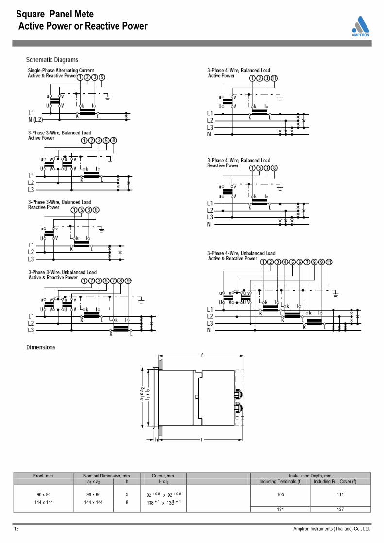
Square Panel Mete Active Power or Reactive Power
Front, mm. Nominal Dimension, mm. Cutout, mm. Installation Depth, mm.
a1 x a2 h I1 x I2 Including Terminals (t) Including Full Cover (f)
96 x 96
96 x 96
5
92 + 0.8 x 92 + 0.8
105
111
144 x 144 144 x 144 8 138 + 1 x 138 + 1
131 137
12 Amptron Instruments (Thailand) Co., Ltd.

.
Square Panel Meters Power Factor
Moving-Coil Movement with Power Factor Converter, 250° Scale Narrow Bezel per DIN 43718
Front Dimensions Type
96 x 96 mm. S-CL96-250
144 x 144 mm. S-CL144-250
Scale Length
Accuracy Class Weight (standard model). Max. Power Consumption, current path voltage path
Nominal Line Voltage phase-to-neutral (=operating voltage ) 3-phase 3-wire systems 3-phase 3-wire systems Test Voltage
Front Housing-Panel Protection
97 mm.
1.5 0.38 kg. 1.0 VA 3.0 VA
≤300 V ≤500 V
≤ 277/480 V 2.2 kV
IP 52
150 mm.
1.5 0.59 kg. 1.0 VA 3.0 VA
≤300 V ≤500 V
≤ 277/480 V 2.2 kV
IP 52
In preparation
Type S-CL96-250
Description
Analog Panel Meter with core-magnet moving-coil movement and integrated Power factor converter. The power factor converter determines the phase angle Between current and voltage. Cos φ is displayed at the moving-coil movement
Nominal Range of Use Limits
Frequency 45 Hz … 65 Hz
Display
Measuring Range Scale Graduation Pointer
Mechanical Design
Housing Material Mounting Fasteners
Scale
Replaceable
Terminals
Terminal Designation Contact Protection
CAP 0.5 … 1 … 0.5 IND Coarse-fine
Beam pointer with knife edge Polycarbonate, self-extinguishing and drip-proof per UL94V-0
or sheet metal housing as option for front dimensions 96 x 96 mm. Standard: S type screw clamp, except for: Screw spindle for 144 x 144 mm. panel meters
Options: se next page Interchangeable scales Scales may only be replaced under voltage-free conditions! Bezels and glass faceplates
May only be replaced under voltage-free conditions! M4 screw terminals with self-lifting terminal clips. Screws can be turned with cross-head or standard screw drivers. Similar to 43807
Finger-safe full cover included
Schematic Diagrams Single Phase Alternating Current
Reference Conditions
Reference Quantities Reference Conditions
Ambient Temperature Position of Use Frequency
Current Components Voltage Components Wave shape Warm-Up Time Other
23 °C ± °C control panel vertical ± °C 50 Hz ± 0.1 Hz
95 … 100% of rated value 98 … 100% of rated value sine, distortion factor ≤ 1% ≥ 5 min DIN EN 60051
Ordering Information
Model
S-CL96 Dimension 96x96 mm. Scale 250Degree. Range
0.5 cap-1-0.5 ind,0.3 cap-1-0.1ind,0.4 cap-1-0.4 ind,0.7 cap-1-0.2ind Class: Standard class 1.5 Input Voltage 100V,110V,115, 220,380,400,440V
Current CT/1A, CT/5A Example S-CL96 AC Power Factor Input 115kV/115V CT 200/5A Range 0.5-1-0.5, class 1.5, Scale 250 Degree
Dimensions
Front in, mm.
Nominal Dimensions, mm. Cutout, mm. Installation Depth Including Terminals (t),mm. M4
Installation Depth Including Terminals (f),mm.
a1 x a2 h I1 x I2
96 x 96 96 x 96 5 92 + 0.8 x 92 + 0.8 54 62.5
144 x 144 144 x 144 8 138 + 1 x 138 + 1 54 62.5
13 Amptron Instruments (Thailand) Co., Ltd.

Square Panel Meters Frequency (pointer-type frequency meters)
Moving-Coil Movement, with Frequency Converter,250° Scale Narrow Bezel per DIN 43718
Front Dimensions 48 x 48 mm. 72 x 72 mm. 96 x 96 mm. 144 x 144 mm. Type S-ZL48-250 S-ZL72-250 S-ZL96-250 S-ZL144-250
Scale Length 37 mm. 63 mm. 97 mm. 150 mm. Weight (standard model). Max. 0.27kg. 0.20 kg. 0.28 kg. 0.49 kg. Power Consumption, Approx. 5 mA 5 mA 5 mA 5 mA Operating Voltage. Max 300 V 600 V 600 V 600 V
Test Voltage 2.2 kV 3.25 kV 3.25 kV 3.25 kV Front Housing-Panel Protection IP 52 IP52 IP52 IP 52
In Preparation
Description
Analog Panel Meter with Core-Magnet Moving Coil Movement and Integrated Frequency Converter or with separate frequency converter
Type S-ZL96-250
Reference Conditions
Reference Quantities Reference Conditions
Ambient Temperature 23°C. ± 2°C. Position of Use control panel vertical ± 1° Input Voltage nominal voltage Wave shape sine, distortion factor 0%
Warm-Up Time ≥ 5 min Other DIN EN 60051
Nominal Range of Use Limits
Input Voltage nominal voltage ± 20% Exception: Frequency converter (Static transducer) 60 … 300 V
Wave shape sine, distortion factor ≤15%
Dimensions
For separate frequency converter ( screw and snap mountable, for top-hat rails Dis EN 50 022 -35 x 7.5 or Din EN 50 022-35 x 15 )
L x B x H = 70 x 45 x 114.5
Dimensions
Display
Scale Graduation Pointer
Mechanical
Design
Housing Material
Mounting Fasteners
Scale Replaceable
Terminals Terminal Designation
Contact Protection
Coarse-fine Beam pointer with knife-edge
Polycarbonate, self-extinguishing and drip-proof per UL94V-0 or sheet metal housing for front panel dimensions of 72 x 72 mm and 96 x 96 mm as option. Standard: S type screw clamp, except:
screw spindle for 144 x 144 mm panel meters Option: see next page Interchangeable scales Scales may only be replaced under voltage-free conditions!
Bezels and glass faceplate May only be replaced under voltage-free conditions! M4 screw terminals with self-lifting terminal clips. Screws can be turned with cross-head or standard screw drivers. “ 11” and “12” , except: “17” and “ 18” for 144 x 144 mm. panel meters Finger-safe full cover included
Order information
S-ZL96 Dimension 96x96mm. Scale 250 Degree
Input Type
Direct 60,100,110,115,120,220,380,415,440V & customize PT Rated 100,110,115,120, 220V or request .
Scale Range
45-55Hz, 45-65Hz, 450-550Hz, 450-650Hz, 550-650Hz Factory standard range or specify when ordering or consult
Class
Class 1.0 is standard or others by request
Example
S-ZL96 Frequency Meter Input PT115kV/115V, Range 45-55Hz Class 1.0, Scale 250 Degree.
Front in mm. Nominal Dimensions, mm. Cutout Dimensions, mm.
I1 x I2
Installation Depth Including Terminals ( t ), mm.
M4
Installation Including Full Cover (f), mm.
a1 x a2 h
48 x 48 48 x 48 5 45 + 0.6 x 45 + 0.6 54 62.5
72 x 72 72 x 72 5 68 + 0.7 x 68 + 0.7 54 62.5
96 x 96 96 x 96 5 92 + 0.8 x 92 + 0.8 54 62.5
144 x 144 144 x 144 8 138 + 1 x 138 + 1 54 62.5
14 Amptron Instruments (Thailand) Co., Ltd.
Frequency
18 17
X
L
N
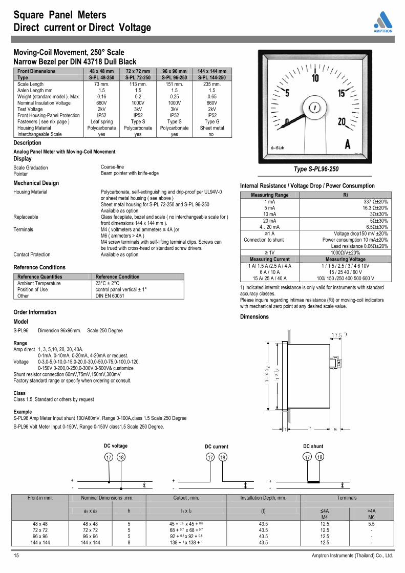
Square Panel Meters Direct current or Direct Voltage
Moving-Coil Movement, 250° Scale Narrow Bezel per DIN 43718 Dull Black
Front Dimensions 48 x 48 mm 72 x 72 mm 96 x 96 mm 144 x 144 mm
Type S-PL 48-250 S-PL 72-250 S-PL 96-250 S-PL 144-250
Scale Length Aalen Length mm Weight (standard model ). Max.
Nominal Insulation Voltage Test Voltage Front Housing-Panel Protection Fasteners ( see nix page )
Housing Material Interchangeable Scale
73 mm. 1.5 0.16
660V 2kV IP52
Leaf spring
Polycarbonate yes
113 mm. 1.5 0.2
1000V 3kV IP52
Type S
Polycarbonate yes
151 mm. 1.5 0.25
1000V 3kV IP52
Type S
Polycarbonate yes
235 mm. 1.5 0.65
660V 2kV IP52
Type G
Sheet metal no
Description
Analog Panel Meter with Moving-Coil Movement
Type S-PL96-250
Internal Resistance / Voltage Drop / Power Consumption
Measuring Range Ri
1 mA 337 Ω±20% 5 mA 16.3 Ω±20%
10 mA 3Ω±30%
20 mA 5Ω±30% 4…20 mA 6.5Ω±30%
≥1 A Connection to shunt
Voltage drop150 mV ±20% Power consumption 10 mA±20%
Lead resistance 0.06Ω±20%
≥ 1V 1000Ω/V±20%
Measuring Current Measuring Voltage
1 A/ 1.5 A /2.5 A / 4 A 1 / 1.5 / 2.5 / 3 / 4 6 10V 6 A / 10 A 15 / 25 40 / 60 V
15 A/ 25 A / 40 A 100/ 150 /250 400 500 600 V
1) Indicated intermit resistance is only valid for instruments with standard accuracy classes.
Please inquire regarding intimae resistance (Ri) or moving-coil indicators with mechanical zero point at any desired scale value.
Dimensions
Display
Scale Graduation Pointer
Mechanical Design
Housing Material
Replaceable
Terminals
Contact Protection
Coarse-fine Beam pointer with knife-edge
Polycarbonate, self-extinguishing and drip-proof per UL94V-0 or sheet metal housing ( see above )
Sheet metal housing for S-PL 72-250 and S-PL 96-250 Available as option Glass faceplate, bezel and scale ( no interchangeable scale for ) front dimensions 144 x 144 mm ).
M4 ( voltmeters and ammeters ≤ 4A )or M6 ( ammeters > 4A ) M4 screw terminals with self-lifting terminal clips. Screws can be trued with cross-head or standard screw drivers.
Available as option
Reference Conditions
Reference Quantities Reference Condition
Ambient Temperature Position of Use
Other
23°C ± 2°C control panel vertical ± 1°
DIN EN 60051
Order Information
Model
S-PL96 Dimension 96x96mm. Scale 250 Degree
Range Amp direct 1, 3, 5,10, 20, 30, 40A. 0-1mA, 0-10mA, 0-20mA, 4-20mA or request. Voltage 0-3,0-5,0-10,0-15,0-20,0-30,0-50,0-75,0-100,0-120,
0-150V,0-200,0-250,0-300V,0-500V& customize Shunt resistor connection 60mV,75mV,150mV,300mV Factory standard range or specify when ordering or consult.
Class Class 1.5, Standard or others by request
Example
S-PL96 Amp Meter Input shunt 100/A60mV, Range 0-100A,class 1.5 Scale 250 Degree
S-PL96 Volt Meter Input 0-150V, Range 0-150V class1.5 Scale 250 Degree.
Front in mm. Nominal Dimensions ,mm. Cutout , mm. Installation Depth, mm. Terminals
a1 x a2 h I1 x I2 (t)
≤4A M4
>4A M6
48 x 48 72 x 72 96 x 96
144 x 144
48 x 48 72 x 72 96 x 96
144 x 144
5 5 5 8
45 + 0.6 x 45 + 0.6 68 + 0.7 x 68 + 0.7 92 + 0.8 x 92 + 0.8 138 + 1 x 138 + 1
43.5 43.5 43.5 43.5
12.5 12.5 12.5 12.5
5.5 - - -
15 Amptron Instruments (Thailand) Co., Ltd.
DC voltage
18 17
X +
-
DC current
18 17
X +
-
DC shunt
17 18
X +
-