standard special provisions - mount pleasant, … water main boring project... · d. city of mt....
TRANSCRIPT

April - 2012
CITY OF MOUNT PLEASANT
STANDARD SPECIAL PROVISIONS

Page 1 of 1
City of Mt. Pleasant
SPECIAL PROVISION
FOR
TECHNICAL SPECIFICATIONS
City of MtPleasant 1 of 1 April 12
GENERAL REQUIREMENT
The 2012 MDOT STANDARD SPECIFICATIONS FOR CONSTRUCTION shall govern all
technical specifications of this contract. The following parts of the contract will prevail over all other
parts in the following order:
A. Special Provisions
B. Supplemental Specifications
C. Project Plans and Drawings
D. City of Mt. Pleasant Standard Special Provisions
E. MDOT Standard Plans
F. MDOT Standard Specifications
G. City of Mt. Pleasant Standard Construction Specifications
The Contractor shall not take advantage of any apparent error or omission in the contract
documents. If any uncertainty, inconsistency, omission, or conflict is discovered in the contract
documents, the Engineer will decide as to the true intent.

Page 1 of 1
City of Mt. Pleasant
SPECIAL PROVISION
FOR
LINES, LEVELS, AND SURVEYS
City of MtPleasant 1 of 1 April 12
Staking by the City of Mt. Pleasant or its agent shall meet the Engineering staking
requirements of Section 104.08A. The contractor shall carefully preserve all benchmarks,
reference points, grade stakes, and other necessary control points and be held responsible for
all errors that may result from their loss or disturbances. The engineer shall make the final
determination as to what lines or grades were disturbed by the contractor.
A minimum of three (3) working days (excluding Saturdays) notice to the City Engineer is
required for staking or re-staking. Re-staking will be at a rate of $75.00 per hour with a
$150.000 minimum.

Page 1 of 2
City of Mt. Pleasant
SPECIAL PROVISION
FOR
Utility Coordination
City of MtPleasant 1 of 2 April 12
The contractor shall cooperate and coordinate construction activities with the owners of utilities as
stated in Section 104.08 of the 2012 MDOT Standard Specifications for Construction. In addition,
for the protection of underground utilities, the contractor shall follow the requirements in Section
107.12 of the 2012 MDOT Standard Specifications for Construction. Contractor delay claims,
resulting from a utility, will be determined based upon Section 109.05E of the 2012 MDOT
Standard Specifications for Construction.
A) General
For protection of underground utilities, the Contractor shall call the Miss Dig system at (800)
482-7171 a minimum of three (3) working days prior to excavating. Members will thus be
routinely notified. This does not relieve the Contractor of the responsibility of notifying utility
owners who may not be a part of the Miss Dig alert system.
B) Coordination with Utilities During the course of the construction, the Contractor will encounter both overhead and underground utilities. The contact information of the utility company representatives are as follows:
Consumers Energy - Electric Richard Klender 1325 Wright Avenue Alma, MI 48801 (517) 466-4279 DTE Energy/MichCon – Gas Dave Newcomb 609 Bjornson Big Rapids, MI 49307 (231) 592-3244 Frontier – Telephone Jeff James 345 Pine Street Alma, MI 48801 (989) 463-0392
Charter Communication – Cable TV Jeff Price 915 E. Broomfield Rd. Mt. Pleasant, MI 48858 (989) 773-7090 City of Mt. Pleasant – Water, Sanitary & Storm Sewer Jason Moore 1303 N. Franklin Ave. Mt. Pleasant, MI 48858 (989) 779-5405 or (989) 779-5401
The Contractor’s attention is directed to existing underground gas mains, which are located
adjacent to or near the work. The Contractor shall use extreme care when working in these areas,
Page 2 of 2
and shall notify DTE Energy/MichCon Gas Company at least three (3) working days in advance
before beginning any excavation in these areas.
C) Relocation
If Utility relocation work is anticipated for this project, contact the appropriate utility company
immediately to coordinate relocations. This will minimize delays to the Contractor’s operations
due to utility work.
Owners of public or private utilities will not be required to relocate utilities in order to facilitate
the operations of construction equipment, unless it is determined by the Engineer that such
poles or structures constitute a hazard to the public or are extremely dangerous to the
Contractor’s operations.
Page 1 of 5
City of Mt. Pleasant
SPECIAL PROVISION
FOR
DIRECTIONAL BORE WATER MAIN MATERIALS AND CONSTRUCTION
City of MtPleasant 1 of 5 April 12
A) Description
This Special Provision addresses the installation of water mains by guided boring, including
connecting to existing water services or other water mains. All gate valve, gate well, and other
appurtenances shall be installed using the Special Provision for Water System Materials and
Construction. The Contractor will provide all labor, components, materials, tools and
appurtenances necessary or proper for the performance and completion of the contract.
Inspection and payment will be by the method stipulated in the contract.
Guided boring is a method of trenchless construction using a surface launched steerable
drilling tool controlled from a mobile drilling frame, and includes a field power unit, mud mixing
system and mobile spoils extraction system. The drilling frame differs from micro-tunneling,
auger boring or pipe jacking equipment. The drilling frame is set back from an access pit that
has been dug at the location of a proposed gate well (or other appurtenances), and a high-
pressure fluid jet toolhead, that uses a mixture of bentonite clay and water, is launched and
guided to the correct invert elevation and line required at the gate well. Using a real-time
guidance system attached behind or within the toolhead, which measures inclination, roll, and
azimuth, the toolhead is guided through the soil to create a pilot tunnel. Tunneling may also
be performed between proposed gate wells or other appurtenances. Upon reaching the pit
dug at the target location, the toolhead is removed and a reamer, with the product pipe
attached, is joined to the arm swing and pulled back through the tunnel. A vacuum spoils
extraction system removes any excess spoils generated during the installation. The gate
wells are then completed at both locations and the surface restored to the original
condition.
1) Qualifications
i) Guided Boring Contractors shall have actively engaged in the installation of pipe
using guided boring for a minimum of three years. The Contractor shall also have
completed at least 5,000 feet of guided boring installations ranging from 6 inches to
24 inches in diameter, in the last year.
ii) Field supervisory personnel employed by the Guided Boring Contractor will have
at least three years’ experience in the performance of this type of work.
2) Site Conditions
i) Guided boring operations must not interfere with, interrupt or endanger the surface
or activity upon the surface, and shall be located as called for on the project
drawings.

Page 2 of 5
ii) Contractor must comply with all applicable jurisdictional codes and OSHA
requirements.
iii) When rock stratum, boulders, underground obstructions, or other soil conditions that
impede the progress of drilling operations are encountered, the Contractor and
Project Engineer will review the situation and jointly determine the feasibility of
continuing drilling operations, by making adjustments or switching to an alternate
construction method.
B) Materials
1) Pipe and Fittings
Restrained Joint PVC Pipe , fittings, and additional appurtenances used shall be in
accordance with the Special Provision for Water System Materials and Construction.
2) Drilling Fluid
i) Drilling fluid shall be a mixture of water and bentonite clay. The fluid shall be inert.
The fluid should remain in the tunnel to ensure the stability of the tunnel, reduce
drag on the pulled pipe, and provide backfill within the annulus of the pipe and
tunnel.
ii) Disposal of excess drilling fluid and spoils shall be the responsibility of the
Contractor, who must comply with all relevant regulations, right-of-way, work space
and permit agreements. Excess drilling fluid and spoils shall be disposed at an
approved location. The Contractor is responsible for transporting all excess drilling
fluid and spoils to the disposal site and paying any disposal costs. Excess drilling
fluid and spoils shall be transported in a manner that prevents accidental spillage
onto roadways. Excess drilling fluid and spoils will not be discharged into sanitary
sewers, storm drain systems or waterways.
iii) Drilling fluid returns (caused by fracturing or formations) at locations other than the
entry and exit points shall be minimized. The Contractor shall immediately clean up
any drilling fluid that surfaces through fracturing.
iv) Mobile spoils removal equipment capable of quickly removing spoils from entry or
exit pits and areas with returns caused by fracturing shall be present during guided
boring operations to fulfill the requirements of paragraphs above.
v) The Contractor shall be responsible for making provisions for a clean water supply
for the mixing of drilling fluid. A permit to use water can be obtained from the
Division of Public Works. No water may be taken from City fire hydrants. The
Contractor shall be responsible for complying with all the requirements of that
permit.

Page 3 of 5
C) Construction
1) General
The Engineer must be notified immediately if any obstruction is encountered that stops
forward progress of drilling operations. The Contractor and Engineer must review the
situation and jointly determine the feasibility of continuing guided boring operations or
switching to an alternative construction method. When it is determined that it is
impossible to continue drilling operations, the Contractor will be directed how to
proceed by the Project Engineer. Dewatering of pits and excavations must meet the
general provisions and specifications for water main construction in effect at the City of
Mt Pleasant. The type of dewatering method will be at the option of the Contractor.
When water is encountered, the Contractor must provide a dewatering system of
sufficient capacity to remove water, keeping any excavations free of water until the
backfill operation is in progress. Dewatering shall be performed in a manner so that
removal of soil particles is held to a minimum.
2) Preparation
Excavate required pits in accordance with the project drawings.
The drilling procedures and equipment shall provide protection to workers, particularly
against electrical shock. As a minimum, grounding mats, grounded equipment, hot
boots, hot gloves, safety glasses, and hard hats will be used by crewmembers. The
drilling equipment shall have an alarm system capable of detecting electrical current.
The Contractor is responsible for existing utilities, as stated under the Miss Dig System.
All utilities that the boring operation may encounter shall be exposed to determine the
actual depth and location. The costs of exposing utilities, whether shown on the plans
or not, shall be the responsibility of the Contractor and included in the bid price for
installing the new water main.
3) Guided Boring Operations
i) Equipment
(1) The drilling equipment must be capable of placing the pipe within the planned
line and grade.
(2) The drilling equipment must have a minimum pullback rating of 35,000 lbs., a
torque rating of 2,000 foot lbs., and mud flow of 24 gallons per minute.
(3) The guidance system must have the capability of measuring inclination, roll and
azimuth. The guidance system must have an independent means to ensure the
accuracy of the installation. The Contractor shall demonstrate a viable method
to eliminate accumulated error due to the inclinometer (pitch or accelerometer).
The guidance system shall be capable of generating a plot of the borehole
survey for the purpose of an as-built drawing. The guidance system must meet
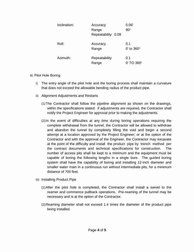
the following specifications.
Page 4 of 5
Inclination: Accuracy 0.06'
Range 90
Repeatability 0.09
Roll: Accuracy 0.1
Range 0' to 360
Azimuth: Repeatability 0.1
Range 0' TO 360
4) Pilot Hole Boring
i) The entry angle of the pilot hole and the boring process shall maintain a curvature
that does not exceed the allowable bending radius of the product pipe.
ii) Alignment Adjustments and Restarts
(1) The Contractor shall follow the pipeline alignment as shown on the drawings,
within the specifications stated. If adjustments are required, the Contractor shall
notify the Project Engineer for approval prior to making the adjustments.
(2) In the event of difficulties at any time during boring operations requiring the
complete withdrawal from the tunnel, the Contractor will be allowed to withdraw
and abandon the tunnel by completely filling the void and begin a second
attempt at a location approved by the Project Engineer; or at the option of the
Contractor and with the approval of the Engineer, the Contractor may excavate
at the point of the difficulty and install the product pipe by trench method per
the contract documents and technical specifications for construction. The
number of access pits shall be kept to a minimum and the equipment must be
capable of boring the following lengths in a single bore. The guided boring
system shall have the capability of boring and installing 12-inch diameter and
smaller water main in a continuous run without intermediate pits, for a minimum
distance of 700 feet.
iii) Installing Product Pipe
(1) After the pilot hole is completed, the Contractor shall install a swivel to the
reamer and commence pullback operations. Pre-reaming of the tunnel may be
necessary and is at the option of the Contractor.
(2) Reaming diameter shall not exceed 1.4 times the diameter of the product pipe
being installed.

Page 5 of 5
(3) The product pipe being pulled into the tunnel shall be protected and supported so
that it moves freely and is not damaged by stones and debris on the ground
during installation.
(4) Pullback forces shall not exceed the allowable pulling forces for the product pipe.
(5) The Contractor shall allow sufficient length of product pipe to extend past the
termination point to allow connections to adjacent pipe sections or gate valves.
Pulled pipes shall be allowed 24 hours of stabilization prior to making tie-ins.
The length of extra product pipe shall be at the Contractor’s discretion and cost.
(6) The Contractor shall install a braided 12 gauge, blue in color, tracer wire at the
same time as the product pipe. The tracer wire shall be connected to each
hydrant at a bolt on the bottom of the hydrant barrel by use of a soldered
connection, a crimped U-shaped connection, or a ring lug.
iv) Water Service Connections
Water service connections shall be made in accordance with the special provision for
Water System Materials and Construction.
D) Testing
Testing shall be done in accordance with the special provision for Water System Materials and
Construction.
E) Measurement and Payment
Payment for the completed work for the various items shall be as described in the Special
Provision for Water System Materials and Construction.
Contract Item (Pay Item) Pay Unit
Water Main, __ inch Bored........................................................ Linear Foot
Water Service - Short, __inch, Bored........................................ Each
Water Service - Long, __inch, Bored........................................ Each

Page 1 of 1
City of Mt. Pleasant
SPECIAL PROVISION
FOR
CURB AND GUTTER, CONC, DET F4
City of MtPleasant 1 of 1 April 12
A) Description
Install Curb and Gutter, Conc, Det F4, Modified according to this Special Provision and as
shown on the plans.
B) Materials
The materials used for this work shall meet the requirements of Section 802.02 of the 2012
Standard Specifications for Construction.
C) Construction
Construct Curb and Gutter, Conc, Det F4, Modified in accordance with the requirements of
Section 802 of the 2012 Standard Specifications for Construction. The material placed directly
under the Curb and Gutter, Conc, Det F4, Modified shall be 22A aggregate, and shall be
included in the bid price for Curb and Gutter, Conc, Det F4, Modified, as detailed on the
proposed cross-section plan sheet. Thickness of this material shall be approximately 1.5
inches for local streets and 2.25 inches for major streets.
D) Measurement and Payment
The complete work as measured for Curb and Gutter, Conc, Det F4, Modified will be paid for
at the contract unit price for the following contract pay items and includes all material,
equipment, and labor to complete this item
Contract Item (Pay Item) Pay Unit
Curb and Gutter, Conc, Det F4, Modified............................... Foot
Page 1 of 1
City of Mt. Pleasant
SPECIAL PROVISION
FOR
DETECTABLE WARNING SURFACE, MODIFIED
City of MtPleasant 1 of 1 April 12
A) Description
This work shall be done in accordance with the requirements of Standard Plan R-28 series
and Section 803 of the 2012 Standard Specifications for Construction except that the
detectable warning plate shall be an asphalt dipped Cast Iron warning plate.
B) Materials
The detectable warning plate shall be an asphalt dipped Cast Iron warning plate meeting
the requirements of section 803 of the 2012 Standard Specifications for Construction.
C) Construction
This work shall be done in accordance with the requirements of Standard Plan R-28 series
and Section 803 of the 2012 Standard Specifications for Construction except that the
detectable warning plate shall be an asphalt dipped Cast Iron warning plate.
D) Measurement and Payment
The complete work as measured for Detectable Warning Surface, Modified will be paid for at
the contract unit price for the following contract pay items and includes all material, equipment,
and labor to complete this item.
Contract Item (Pay Item) Pay Unit
Detectable Warning Surface, Modified.................................. Foot

Page 1 of 2
City of Mt. Pleasant
SPECIAL PROVISION
FOR
DR STRUCTURE COVER, ____ , MODIFIED
City of MtPleasant 1 of 2 April 12
A) Description
Dr Structure Cover, ____, Modified, hereinafter referred to as Cover, shall consist of
materials and work as described in Section 403 of the Michigan Department of Transportation
2012 Standard Specifications for Construction except as modified herein.
B) Materials
Covers shall include geotextile fabric, frame, grate or cover and shall be of the type
indicated on the plans.
1) Dr Structure Cover, CB , Modified
Catch basin cover types shall depend on their location on the plans.
i) Catch basins covers located in Det M openings shall be model 5100Z with type M1
grate as manufactured by East Jordan Iron Works, or approved equal.
ii) All other catch basins covers located in the curb shall be model 7000 with type M2
grate as manufactured by East Jordan Iron Works, or approved equal.
iii) Unless otherwise indicated on the plans, catch basins covers outside of the curb shall
be model 1040 with type M1 grates as manufactured by East Jordan Iron Works, or
approved equal.
2) Dr Structure Cover, STM, Modified
i) Storm drainage structure covers shall be model 1040 with type B cover as
manufactured by East Jordan Iron Works, or approved equal.
3) Dr Structure Cover, SAN, Modified
i) Sanitary drainage structure covers shall be model 1040 with type A cover as
manufactured by East Jordan Iron Works, or approved equal. The preferred cover
shall be stamped with the City of Mt. Pleasant logo.
C) Construction
Construct drainage structure covers according to the details on the plans and section 403 of
the Standard Specifications. Drainage structure shall be wrapped with geotextile fabric as
shown on the plans.
Page 2 of 2
D) Measurement and Payment
This work will be measured and paid as specified in section 403 & 802 of the Standard
Specifications using the following contract items (pay items).
Contract Item (Pay Item) Pay Unit
Dr Structure Cover, CB, Modified.......................................... Each
Dr Structure Cover, STM, Modified....................................... Each
Dr Structure Cover, SAN, Modified....................................... Each
Page 1 of 1
City of Mt. Pleasant
SPECIAL PROVISION
FOR
DRIVEWAY OPENING, CONC, DET M, MODIFIED
City of MtPleasant 1 of 1 April 12
A) Description
Construct Driveway Opening, Conc, Det M, Modified in accordance with the requirements
of Standard Plan R-29 series and Section 802 of the 2012 Standard Specifications for
Construction.
B) Materials
The materials used for this work shall meet the requirements of Section 802.02 of the 2012
Standard Specifications for Construction except that the reinforcing steel shall be eliminated.
C) Construction
Construct Driveway Opening, Conc, Det M, Modified in accordance with the requirements
of Standard Plan R-29 series and Section 802 of the 2012 Standard Specifications for
Construction except that the reinforcing steel shall be eliminated. The approximate 2 inches to
2.5 inches of material placed under the Construct Driveway Opening, Conc, Det M, Modified
shall be 22A aggregate, and shall be included in the bid price for Construct Driveway Opening,
Conc, Det M, Modified.
Measurement and Payment
The complete work as measured for Driveway Opening, Conc, Det M, Modified will be paid
for at the contract unit price for the following contract pay items and includes all material,
equipment, and labor to complete this item.
Contract Item (Pay Item) Pay Unit
Drive Opening, Conc, Det M, Modified................................ Foot
Page 1 of 1
City of Mt. Pleasant
SPECIAL PROVISION
FOR
GAS/WATER SHUTOFF COVER ADJ, CASE 1
City of MtPleasant 1 of 1 April 12
A) Description
Adjust gas and water shutoff covers according to this Special Provision and as shown on
the plans.
B) Materials
The materials used for this work shall meet the requirements of the utility owning the
shutoff.
C) Construction
Adjust gas and water shutoff covers in accordance with the requirements of Section 403.03
C of the 2012 Standard Specifications for Construction for drainage structures.
D) Measurement and Payment
The complete work as measured for Gas/Water Shutoff Cover, Adj, Case 1 will be paid for
at the contract unit price for the following contract pay items and includes all material,
equipment, and labor to complete this item
Contract Item (Pay Item) Pay Unit
Gas/Water Shutoff Cover, Adj, Case 1................................. Each
Page 1 of 1
City of Mt. Pleasant
SPECIAL PROVISION
FOR
HMA APPLICATION ESTIMATE - LOCAL STREET
City of MtPleasant 1 of 1 April 12
A) Description
This work shall be done in accordance with the requirements of section 501 of the 2012
Standard Specifications for Construction and applicable supplemental specifications and
special provisions, and as specified herein. The HMA Approach bid item shall include paving
of HMA Driveways and cross streets. Cross streets shall be constructed in two passes at the
same cross-section as the mainline pavement, follow the procedures outlined in MDOT
501.03F4
B) Materials
The HMA leveling course and HMA Approach shall be HMA, 13A. The HMA top course
shall be HMA, 36A.
The leveling course shall have a yield of 175 pounds per square yard and the binder shall be
PG 56-28
The top course shall have a yield of 125 pounds per square yard, an AWI of 260, minimum,
and the binder shall be PG 58-28.
HMA Approach shall be 13A. Cross streets shall be constructed in two passes, have a yield of
300 pounds per square yard, and the binder shall be PG 58-28. Driveways shall be
constructed in one pass, have a yield of 220 pounds per square yard, and the binder shall be
PG 58-28.
The HMA Bond Coat material shall be per Section 501.03. The uniform rate of application
shall be 0.05 - 0.15 gallons per square yard.
Page 1 of 1
City of Mt. Pleasant
SPECIAL PROVISION
FOR
HMA APPLICATION ESTIMATE - MAJOR STREET
City of MtPleasant 1 of 1 April 12
A) Description
This work shall be done in accordance with the requirements of section 501 of the 2012
Standard Specifications for Construction and applicable supplemental specifications and
special provisions, and as specified herein. The HMA Approach bid item shall include paving
of HMA Driveways and cross streets. Cross streets shall be constructed in two passes at the
same cross-section as the mainline pavement, follow the procedures outlined in MDOT
501.03F4
B) Materials
The HMA leveling course, top course, and HMA Approach shall be HMA, 13A.
The leveling course shall have a yield of 220 pounds per square yard and the binder shall be
PG 56-28
The top course shall have a yield of 165 pounds per square yard, an AWI of 260, minimum,
and the binder shall be PG 58-28.
HMA Approach shall be 13A. Cross streets shall be constructed in two passes, have a yield of
385 pounds per square yard, and the binder shall be PG 58-28. Driveways shall be
constructed in one pass, have a yield of 220 pounds per square yard, and the binder shall be
PG 58-28.
The HMA Bond Coat material shall be per Section 501.03. The uniform rate of application
shall be 0.05 - 0.15 gallons per square yard.

Page 1 of 1
City of Mt. Pleasant
SPECIAL PROVISION
FOR
MACHINE GRADING, MODIFIED
City of MtPleasant 1 of 1 April 12
A) Description
This work shall consist of all excavation, including earth, necessary to shape the subgrade
to the cross-sections shown on the plans for pavements, sidewalks, curbs, drive approaches,
etc., within the right-of-way of the project. The work shall include proper disposal of excavated
materials. This work shall also include all embankments necessary to shape areas behind
curb and gutter, around all drives and sidewalks to grade to allow for placement of topsoil.
B) Materials
This work shall conform to the requirements of Section 205 of the Michigan Department of
Transportation 2012 Standard Specifications for Construction of machine grading, earth
excavation, embankment and density except as modified herein.
C) Measurement and Payment
Machine Grading, Modified will be measured by length in Stations along the street
centerline and will be paid for at the contract unit price per Station, which price shall be
payment in full for all labor, equipment and materials, including embankment, excavation and
disposal of excavated material needed to accomplish this work, on both sides of the street and
any any adjacent side streets to the limits shown on the plans
Suitable excavated material as determined by the Engineer may be used as fill material
behind proposed curb. Use of excavated material for fill material will be considered as
included in the work of Machine Grading, Modified.
The completed work as measured for Machine Grading, Modified will be paid for at the
contract unit price for the following contract item (pay item).
Contract Item (Pay Item) Pay Unit
Machine Grading, Modified.................................................... Station
Page 1 of 3
City of Mt. Pleasant
SPECIAL PROVISION
FOR
MAINTAINING TRAFFIC
City of MtPleasant 1 of 3 April 12
A) Description
Traffic shall be maintained throughout the project according to sections 104.11 and 812 of
the Michigan Department of Transportation 2012 Standard Specifications and as specified
herein. The Contractor shall for the safety and protection of through and local traffic, furnish,
erect, and maintain traffic control devices as shown on the plans and as directed by the
Engineer. The Contractor shall remove the traffic control devices in a prompt, safe, and orderly
manner upon completion of the work or when directed by the Engineer.
The Contractor shall maintain access to business and residential driveways at all times as
described herein.
The Contractor shall notify the Engineer a minimum of 72 business hours prior to the
implementation of any detours, street closures, or lane closures.
Traffic control elements, traffic control devices, barricade lighting, barricade spacing, taper
lengths, etc., shall conform to the requirements of the 2005 edition of the Michigan Manual of
Uniform Traffic Control Devices as amended, unless otherwise specified herein. This includes
advance warning signs, barricades and channeling devices at intersecting streets, on which
traffic is to be maintained.
The Contractor is required to contact all local and state police, fire, emergency services that
have jurisdiction within the construction influence area a minimum of five (5) calendar days
prior to the implementation of any lane closure or detours.
Changes and/or adjustments to the maintaining traffic plans and standards may be applied as
determined by the Engineer.
1) Construction Influence Area (CIA)
The CIA shall include the right-of-way of the street where work is to take place from the
beginning to the end of the construction signing and inclusive of all the construction
signing on the intersecting streets & detours.
B) Materials
All traffic control devices and their usage shall conform to the 2005 edition of the
Michigan Manual of Uniform Traffic Control Devices as amended, and as specified as
herein.
Construction signing shall be required as shown in the Maintaining Traffic plan sheets.
Signs, barricades, and plastic drums shall be cleaned over the entire surface as required by
the Engineer.

Page 2 of 3
1) Temporary Signs
All signs must be approved by the Engineer prior to use.
All diamond-shaped warning signs shall be 48” x 48” mounted at a 7’ minimum bottom height. Distances shown between construction warning, regulatory, and guide signs shown on the plans and typical are approximate and may require field adjustment, as directed by the Engineer.
All temporary signs shall be constructed with legends and symbols flush to the sign’s face and not extending beyond the sign borders or edges. Temporary warning, regulatory, and guide signs not required for a particular work Operation shall be removed, completely covered, or laid down with the legs off, as directed by the Engineer.
C) Construction
The contractor shall limit street excavation activities to 300 feet at a time. The contractor’s
backfill and aggregate base placement shall follow closely behind, such that no more than 300
feet of road shall be without existing pavement or a minimum of four (4) inches of compacted
gravel on the sub-base.
1) Residential Access
Access to driveways for local residents and businesses shall be maintained and available for use. All driveways shall be open when the contractor is not working, including all evenings, nights, Sundays, and holidays except as approved in writing by the inspector and with written notifications to the residents/owners by the contractor.
2) Street Closures
Streets within 300 feet (one block) of construction operations may be closed only to through traffic. All other streets and intersections shall be open to all traffic and maintained in good driving condition by the contractor at all times. Intersections shall be open to cross street traffic except when construction work is in progress in those intersections. No more than one intersection may be closed at a time.
3) Residential Refuse and Recycling Collection
The city contractor for trash (refuse) is Republic Services/Allied Waste, 877-698-7274, and MMI Industries, 989-773-6918, for recycling. Collection begins at 7:30 a.m. The contractor shall schedule the work to allow and provide access for refuse and recycling contractors to provide their services to the residential properties. If the refuse and recycling contractors are unable to collect materials due to construction operations, then the construction contractor shall collect and deliver the refuse and recyclable material to a cross street for collection at no cost to the City. It is the responsibility of the construction contractor to contact the refuse and recycling contractors to coordinate operations.
Page 3 of 3
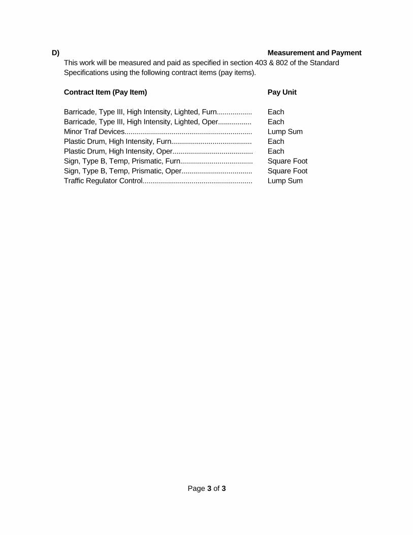
D) Measurement and Payment
This work will be measured and paid as specified in section 403 & 802 of the Standard
Specifications using the following contract items (pay items).
Contract Item (Pay Item) Pay Unit
Barricade, Type III, High Intensity, Lighted, Furn.................. Each
Barricade, Type III, High Intensity, Lighted, Oper................. Each
Minor Traf Devices................................................................. Lump Sum
Plastic Drum, High Intensity, Furn......................................... Each
Plastic Drum, High Intensity, Oper......................................... Each
Sign, Type B, Temp, Prismatic, Furn..................................... Square Foot
Sign, Type B, Temp, Prismatic, Oper.................................... Square Foot
Traffic Regulator Control........................................................ Lump Sum

Page 1 of 4
City of Mt. Pleasant
SPECIAL PROVISION
FOR
PRECONSTRUCTION AUDIO VIDEO RECORDING
City of MtPleasant 1 of 4 April 12
A) Description
The work covered under this special provision consists of furnishing all labor, materials and
equipment to provide High Definition color video recording along the entire length of the
project to serve as a record of "original" conditions.
B) Equipment
All audio-video taping equipment shall be supplied and operated by a professional firm
actively engaged in pre-construction audio-video recording.
C) Inspection
1) Requirements
Prior to commencing any other work, a continuous color audio-video recording shall be
made of the project.
i) Coverage Area
Shall include all above ground features located within the zone of construction
influence. Of particular concern are any existing faults, fractures, defects or other
imperfections exhibited by any above ground features.
2) Qualifications
The audio-video and photography shall be performed by a professional, qualified,
established audio-video recording firm knowledgeable in construction practices which
have a minimum of one year of experience in the implementation of established inspection
procedures.
3) Acceptance of Recording
The City reserves the right to reject the audio-video recording because of poor quality,
unintelligible audio, or uncontrolled pan or zoom. Any recording rejected by the City shall
be re-recorded at no cost to the City. Under no circumstances shall construction begin
until the City has received and accepted the audio-video recording.
4) Equipment
When conventional wheeled vehicles are used for recording, the distance from the camera
lens to the ground shall not be less than twelve (12) feet to insure proper perspective. In
some instances, audio-video coverage will be required in areas not accessible on
conventional wheeled vehicles. Such coverage shall be obtained by walking or special
conveyance approved by the Engineer.
Page 2 of 4
i) Audio-Video Recording Media
The audio-video recording provided shall be a color cassette utilizing the VHS format
and shall be compatible with the City’s tape player or in a DVD format.
ii) Camera(s)
A color video camera shall be used that shall have High Definition recording capability.
The camera shall be a professional quality camera acceptable to the Engineer.
5) Execution
i) Audio
Each tape shall begin with the current date, project name, project number and
municipality, and be followed by the general location; i.e. name of the street or location
of "cross country" line, viewing side and direction of progress.
ii) Video
To preclude the possibility of tampering or editing in any manner, all video recordings
shall, by electronic means, display continuously and simultaneously generated
transparent digital information to include the date and time of recording, as well as the
corresponding engineering stationing numbers. The date information will contain the
month, day and year. For example, 3/16/01, and shall be placed directly below the
time information. The time information shall consist of hours, minutes, and seconds,
separated by colons. For example, 11:25:14. This transparent information shall
appear on the extreme upper left-hand third of the screen.
(1) Engineering Station Numbers
Station numbers shall be continuous, accurate, correspond to the project stationing
and include the standard engineering symbols (for example, 16+50). This
information shall appear in the lower half of the viewing screen.
(2) Additional Information
Below the engineering stationing, periodic transparent alphanumeric information,
consisting of the name of the project, name of the area covered, direction of travel,
viewing side, etc., shall appear.

Page 3 of 4
iii) Audio-Video Tracks
The audio-video recording shall consist of one (1) video and two (2) audio tracks, all of
which shall be recorded simultaneously. All tracks shall consist of original, live
recordings and, thus, shall not be copies of other audio or video recordings. Audio
track 1 shall contain the narrative commentary of the camera operator, recorded
simultaneously with his fixed elevation video record of the zone of influence of
construction. Audio Track 2 shall contain the narrative commentary and evaluations of
the ground level remote technician whose function shall be to provide a complete
circumspection of any features not adequately visible to the camera operator and to
describe in detail the extent of any damage encountered. In order to maintain viewer
orientation, transition from fixed camera overview to remote camera picture shall be by
means of an electronic dissolve.
iv) Lighting Requirements
All taping shall be done during times of good visibility. Auxiliary lighting may be
required to fill in shadow areas and/or when recording inside a building. The lighting
shall be sufficient to illuminate all details in the area. Lighting shall be required upon
the request of the Engineer.
v) Recording Coverage
Recording coverage shall include all surface features located within the zone of
influence of construction specified on the plans and supported by appropriate audio
description. Audio description shall be made simultaneously with video coverage.
(1) Coverage
Video coverage shall include, but not be limited to, all existing driveways,
sidewalks, curbs, ditches, streets (including condition of paving for full width),
landscaping, trees, culverts, catch basins, manholes, headwalls, retaining walls,
fences, visible utilities, and all buildings located within the zone of influence. Of
particular concern are any existing faults, fractures, defects, or other imperfections
exhibited by the above-mentioned surface features.
(2) Houses and Buildings
Structures shall be identified visually by house or building number, when possible,
in such a manner that the progress of the tape and the proposed construction may
be located by reference to the houses and buildings.
(3) General
Taping shall not be done during periods of visible precipitation or when more than
10% of the ground area is covered with snow, leaves, floodwaters or debris, unless
otherwise authorized by the Engineer.
Page 4 of 4
(4) Rate of Speed
The rate of speed in the general direction of travel of conveyance used during
taping shall not exceed 48 feet per minute. Panning rates and zoom-in, zoom-out
rates shall be controlled sufficiently such that the rates will produce clarity of the
object viewed during playback of the tapes.
(5) Coverage Area
The Engineer shall have the authority to designate areas that may be omitted or
added for audio-video coverage.
(6) Identification
(a) Tape Cassettes and Tape Cases
Cassettes and cases shall be properly identified by tape number, location and
project name and municipality in a manner acceptable to the Engineer.
(b) Records
A record of the contents of each tape shall be supplied by a sheet identifying
each segment of the tape by location; i.e. roll number, street or road viewing,
tape counter number, viewing side, point starting from, traveling direction and
ending destination point.
D) Measurement and Payment
The complete work as measured for Preconstruction Audio Video Taping will be paid for at the
contract unit price for the following contract pay item and includes all material, equipment, and
labor to complete the item.
Contract Item (Pay Item) Pay Unit
Preconstruction Audio Video Recording.................................. Lump Sum

Page 1 of 3
City of Mt. Pleasant
SPECIAL PROVISION
FOR
RESTORATION, MODIFIED
City of MtPleasant 1 of 3 April 12
A) Description
This work shall include all labor, materials and equipment to clean up and restore public
and private ground to a condition equal to or better than that which existed prior to
construction. This includes removal and legal disposal of all construction debris, litter, and
materials.
B) Materials
1) Topsoil
Black dirt or natural surface soil, high in organic material, free from stones, brush, debris,
objectionable weeds, or other litter, and approved by the City Engineer prior to spreading.
The engineer may perform a soil test prior to approval. Peat material is not acceptable.
2) Fertilizer
Fertilizer shall be commercial seed starting 20-10-10 grade supplied in the manufacturer's
packaging with composition clearly marked. Bulk fertilizer may be used when certified
delivery slips are furnished by the Contractor, meeting section 816 of the 2012 MDOT
specifications.
3) Seed
Seed material and application shall meet section 816 of the 2012 MDOT specifications,
using TUF seed mixture.
4) Mulch and Adhesive
Mulch and adhesives shall meet section 816 of the 2012 MDOT specifications, for wood
fiber mulch. Paper mulch or straw are not acceptable.
C) Construction
1) Preparation of Seed Bed
i) Grading
Grades on areas to be seeded shall be maintained in a true and even condition.
Where the grades are not defined, they shall be established by the Contractor to blend
with existing adjacent grades without irregularities and shall provide for proper
drainage.
Page 2 of 3
ii) Placing Topsoil
Topsoil shall be evenly spread by blade graders, or other approved methods, to a
minimum depth of four inches (4”). Any irregularities in the surface resulting from
topsoiling or other operations shall be corrected in order to prevent the formation of
depressions where water will stand. Topsoil shall not be placed until the subgrade has
been smoothly graded and compacted, and the engineer or inspector approves the
subgrade in writing.
iii) Application of Fertilizer
Fertilizer shall meet the requirements of section 812 of the 2012 MDOT specifications
for Class A fertilizer.
iv) Cleanup
After completion of the above operations, the surface shall be cleared of stones, roots,
brush, wire, grade stakes, and other objects that might be a hindrance to maintenance
operations.
2) Seeding
TUF seed mixture meeting requirements of section 816 of the 2012 MDOT specifications
shall be used on all lawn areas and adjacent backslopes. No seeding shall be done until
the Engineer has inspected the seed container and has given written approval of the
topsoil. Seeding for erosion control measures shall be cereal rye seed.
3) Mulching
i) Straw and Hay Mulch
As part of the seeding and fertilizing operations, wood fiber mulch shall be spread over
the surface as required in section 816 of the 2012 MDOT specifications. Paper mulch
is not acceptable.
ii) Mulch Adhesive
Mulch shall be held in place by a spray coating of mulch adhesive. The Contractor
shall protect all traffic, signs, structures, and other objects from being marked or
disfigured by the adhesive material. Fire hydrants shall be covered prior to the
placement of all sprayed materials. Adhesive material shall be applied uniformly at a
rate of 400 gallons per acre, sprayed simultaneously with the mulch, or a surface
application of adhesive sprayed immediately following mulching.
4) Establishment of Seeded Areas
The Contractor shall be responsible for the proper care of the seeded area during the
period when the grass is becoming established, and shall be responsible for a total grass
cover. The acceptance of the work will not be given until grass cover is established.
Page 3 of 3
i) Watering
Seeded areas shall be watered whenever excessive drying is evident during the period
set for establishment of the seeded area. The Contractor shall be responsible for the
proper care of the seeded areas and for the establishment of a uniform stand of grass
until final acceptance of the entire work covered by the Contract.
The City has established a program to encourage residents to water the newly seeded
areas, to help establish the lawn. Residents will be given a credit on their water bill for
watering the newly seeded areas.
ii) Weeds
After the grass has become established, if it appears to have more than ten percent
(10%) weeds, the Contractor shall spray with an approved herbicide (weed killer).
D) Measurement and Payment
Restoration, Modified shall be paid for by the square station as measured along the project
centerline and will include all work necessary to restore both sides of the street. The price paid
shall be payment in full for all Restoration, Modified work.
Contract Item (Pay Item) Pay Unit
Restoration, Modified............................................................. Station

Page 1 of 10
CITY OF MT. PLEASANT SPECIAL PROVISION
FOR SANITARY SEWER MATERIALS AND CONSTRUCTION
1 of 10
DESCRIPTION The Contractor shall furnish all labor, equipment, and materials to completely construct, test, and place in operation, the sanitary sewer system as shown on the Plans and specified herein. MATERIALS A. Service Pipe Six-inch (6") service pipe used for riser pipe and house leads shall be constructed of the following material: PVC conforming to D-3034 with 0.180-inch wall thickness (SDR-35).
Joints and couplings shall conform to ASTM D-3212. Pipe shall have a home mark, and shall not be blue in color.
B. Sewer Main Pipe Unless otherwise specified on the Plans or Proposal form, the Contractor shall utilize the following materials, subject to Specifications and size limitations. Sewer pipe materials may be changed only at manholes. 1. Eight-inch (8") diameter through fifteen-inch (15") diameter pipe - Shall be
SDR 35 PVC sewer pipe meeting the requirements of ASTM D-3034. 2. Sixteen-inch (16") diameter pipe and larger - Shall be SDR 35 PVC pipe
meeting the requirements of ASTM F-679. 3. Joints shall meet ASTM D-3212 push on type with seating mark. Service
lead connections shall be made using standard wye fittings. C. Manholes 1. Pre-Cast Sections Manholes shall be constructed of circular pre-cast concrete units with circular reinforcement and shall conform to the requirements of the current Specifications for Pre-Cast Reinforced Concrete Manhole Risers and Tops ASTM C-478.

Page 2 of 10
Marking of the sections shall be done within six (6) days after manufacture. Certification from the manufacturer that the manholes supplied meet the required Specifications shall be provided to the Engineer by the Contractor. Cone sections shall be the eccentric type with a minimum depth of 12”. Joints between sections shall be rubber O-ring gasket. Mastic sealing compound will not be accepted. Manhole connections shall be made with an integrally cast seal system, such as "Kor-N-Seal", "Lock-Joint Flexible Manhole Sleeve", or an approved equal. Connections to existing manholes (without flexible coupling) with PVC pipe shall be made using a water stop cemented to the plastic pipe. 2. Manhole Steps Manhole steps shall be plastic-coated steel. They shall be placed sixteen-inches (16") apart unless otherwise shown and shall be cast in the manhole walls. It will not be acceptable to grout the steps in place after the manhole section is poured. Plastic-coated steel steps shall consist of a 3/8-inch diameter deformed steel reinforcing rod covered with a copolymer polypropylene plastic. The steel rod shall be grade 60 and conform to the ASTM A-615. The plastic shall conform to ASTM 2146-68, Type II, Grade 49108. Steps shall also conform to the following standards: a. Michigan Department of Labor Occupational Safety Standards, Part
3, Rule 341. b. ASTM C-478. c. OSHA 1910.27 G 3. Castings Manhole frames and covers shall be EJIW 1040 or equal. The preferred casting shall be stamped with the City of Mt. Pleasant logo, available at East Jordan Iron Works. Castings shall have a minimum clear internal opening of 24 inches. Top of casting shall be set as follows:
a. Flush with paved or grass surfaces. b. Four-inches (4”) below gravel road surface with eight-inches

Page 3 of 10
(8”) of adjustment. 4. Cement Mortar Mortar for block and brick work in manholes and other appurtenances shall be mixed in the proportion of one (1) part Portland cement to three (3) parts sand. Hydrated lime may be added in proportions not to exceed ten percent (10%) of the volume of the cement. 5. Adjusting Rings Casting adjustments shall be accomplished with pre-cast concrete grade rings conforming to ASTM C478. Rings shall have an ID not less than twenty-four-inches (24") nor greater than twenty-five inches (25"), a minimum thickness of two-inches (2"), and a minimum OD of forty-inches (40"). 6. Brick and Block Fill-in around pipes shall be accomplished with bricks and/or blocks. Brick shall be concrete confirming to ASTM C-55, Grade N. Block shall be concrete conforming to ASTM C-139. 7. Concrete Concrete used in manhole construction shall be transit mixed with a twenty-eight (28) day compressive strength of 3,000 psi. The approximate proportions of the mix shall be one (1) part cement, two (2) parts fine aggregate, and three (3) parts coarse aggregate. The mix shall contain six (6) sacks of cement per cubic yard with a maximum allowable slump of three and one half-inches (3 1/2"). CONSTRUCTION
A. Sewer Main Polyvinyl chloride (PVC) pipe shall be installed according to the UniBell Plastic Pipe Association Recommended Standards and Practices, and shall conform to ASTM D2321. The installation, handling, and storage of all pipe shall be in accordance with manufacturer's recommendations. Pipe shall be protected at all times against impact, shocks, and free fall. Stockpiling of pipe at the job site shall be in such a location as to minimize handling. Trenches for pipe shall be excavated so that there will be a minimum clearance of six-inches (6") on each side of the barrel of the pipe and a maximum width of trench at

Page 4 of 10
the level of the top of the pipe of not more than 16 inches greater than the OD of the pipe 30 inch ID or smaller and not more than 24 inches greater than the OD of pipe 33 inch ID or larger. There shall be, at all times, sufficient width to permit the pipe to be laid and to permit first-class construction methods to be used. Sufficient space shall be provided in the trench to permit the joint to be properly made. The trench bottom shall be undercut a minimum of four-inches (4") below the final location of the pipe and the trench then filled with Class II sand or crushed stone compacted with hand tampers to provide a cushion for bedding the pipe. The bedding material shall be free of stone over 1 ½ inches in size. The trench shall be dry during the pipe laying operation. Bell holes shall be excavated so that after placement, the barrel of the pipe will have full bearing on the trench bottom. The laying of pipe shall commence at the outlet and proceed upgrade with spigot ends pointing in the direction of flow. All pipe shall be laid to the line and grade called for on the Plans utilizing an in-line laser beam system for vertical and horizontal control. Each pipe, as laid, shall be checked by the Contractor with a suitable target to insure that this result is obtained. Vertical elevation of the invert shall, at any point, be within plus or minus 0.04 foot (1/2-inch) of plan elevation. Horizontal alignment must meet the same tolerance. Joints shall be made in accordance with the manufacturer's requirements. The socket of the pipe last laid shall be wiped clean and the spigot end of the pipe to be laid shall then be centered and pushed home to the stop mark. The pipe shall be centered so that they will form a sewer with a uniform invert. After the pipe is laid, Class II sand, fine gravel or crushed stone shall be placed the entire width of the trench up to the spring line of the pipe. Backfill shall be carefully tamped under the haunches of the pipe. Care shall be taken during backfilling and tamping so that the line and grade of the pipe are not disturbed. After compacting, Class II sand, fine gravel or crushed shall be placed until the entire width of the trench is filled to not less than one foot (1') above the top of the pipe. The maximum stone size for backfill material within one foot (1’) of the top of pipe shall be 1 ½ inches. If sand is used for backfill around and over the pipe, it shall be thoroughly compacted with a vibratory compactor; hand compaction will not be acceptable. The remainder of the backfilling may be done with Class II sand backfill. All backfill is to be compacted in maximum one-foot (1') lifts to a density of ninety-five percent (95%) of the maximum unit weight as determined by the modified proctor and shall contain no debris, frozen material, organic material, etc., within two feet (2’) of the top of the pipe. Unless crushed stone is used as backfill around the pipe, the use of a hoe pack will not be allowed for compaction.

Page 5 of 10
Main sewer line stubs for future connections shall be furnished and placed by the Contractor according to details shown on the drawings and as directed by the Engineer. The end of the stub where future connections will be made shall be properly supported on crushed stone or concrete and braced when not resting on original ground so that any settlement will not disturb the connection. The end of the main sewer line stub shall be witnessed and marked in the manner described for sanitary sewer leads. Excavation for structures shall be extended sufficiently beyond the limits of the structure to provide ample room for form construction, backfill compaction, and other construction methods to be followed, wherever necessary. In case soft material is encountered in the bottom of a sewer trench or underneath a drainage structure which, in the opinion of the Engineer, is not suitable for supporting the pipe, the Engineer may order the removal of this soft material and its replacement with crushed stone, concrete or other material in order to make a suitable foundation for the construction of the sewer structure. Where the construction is on or along the line of an existing sewer, the Contractor shall maintain sanitary sewer services by means of bypass pumping or other methods approved by the Owner. The pumps, when used, shall be large enough to handle the peak daily flow of the pipe which is being bypassed. If flow exceeds the pump capacity, the plugs shall be pulled allowing the flow to pass through the downstream sewer. When plugs are used to control flow or for pumping, they shall be of the pneumatic type to allow for quick release without entering the manhole. If sand bags are used to block a downstream pipe in a manhole, each bag shall be tied off with a rope to allow removal of the sand bag without entering the manhole. Flow control shall be monitored so that surcharging of sewers, flooding of private or public property (including basements) does not occur. Any damage caused by the control of flow shall be the Contractor's responsibility to repair, correct or indemnify. Smaller sewers with low flow, which must be temporarily blocked, shall use the bypass pumping procedure or temporary fluming to maintain flow. The Contractor shall be responsible for any damage that may result from failure to maintain sewer flow. B. Service Leads 1. Riser Pipe
Page 6 of 10
Where shown on the Plans or where directed by the Engineer, the Contractor shall put in six-inch (6") pipe risers extending from the branch connection in the sewer up to within eleven-feet (11') of the ground surface or to a depth adequate to serve the house lead elevation shown at the property line. These pipes shall be laid up with a joint as specified, and the top pipe shall be closed with a stopper. All risers shall be laid up and held securely in place and the backfill shall be carefully placed around them so as not to disturb them. One-inch (1") crushed stone, six-inches (6") thick shall be placed under and around the "Y" branch and over it to a height of six-inches (6") above the sewer to furnish an adequate support to the riser pipe. The top of each riser pipe shall be measured and recorded by the Contractor in the same manner as specified for measuring and marking stub connections. 2. Sewer Leads Sewer leads shall be installed at the locations and elevations shown on the Plans or as directed by the Engineer. Before sewer leads are installed, the Contractor shall confirm the exact location with the property owner, if property is occupied. On vacant lots, the sewer leads will generally be located at approximately the mid-point of the front lot line, unless the owner requests another location. The sewer leads shall connect to the six-inch (6") wye or six-inch (6") riser and generally extend to the street right-of-way line. All sewer leads that do not have other pipe connected to them immediately shall be fitted with suitable stoppers and braced for pressure tests. In order to properly mark the location of every wye, riser, clean out, and sewer lead, the Contractor shall make accurate measurements of each installation before the sewer lead is backfilled. The measurements shall indicate the distance from each wye to the center of the downstream manhole. The measurement of risers, clean outs, and sewer leads shall indicate the distance from the main line sewer and to two (2) fixed reference points, i.e. fire hydrants, manholes, building corners. The Contractor shall furnish the Engineer with a copy of these measurements immediately upon the completion of each street. In addition to measurements, the Contractor shall furnish and place a treated two inch by four inch (2" x 4") marking stick at each lead of such length that it will reach from the lead to within six-inches (6") of the ground surface. Each marker shall be set in a vertical position and held vertical while backfilling the trench. Two (2) 16-penny common nails shall be driven into the top of each two inch by four inch (2” x 4”) marking stick so the sewer lead location may be found with a magnetic locator. 3. Tapping Existing Mains
Where existing main sewer lines are to be tapped, the Contractor shall use a pre-
Page 7 of 10
formed saddle approved by the Engineer. A hole shall be cored to the proper size in the main line and all rough edges smoothed to prevent obstructions. Tap shall be horizontal to forty-five (45) degrees above horizontal. No vertical taps are allowed. The exterior of the main line pipe shall be thoroughly cleaned in order to provide a prepared surface for gluing the saddle onto the main line. The Contractor shall clean the main line of all debris, which may enter during his tapping operation. The Contractor shall insure that the sewer lead does not protrude into the main. The Contractor shall notify the Engineer prior to making any connection to the main line and shall not backfill the connection prior to approval of the Engineer. If the pipe becomes covered with water or backfill material, the Contractor shall remove the water or material to facilitate the inspection. C. Manholes Sanitary sewer manholes are to be constructed as shown on the detailed drawings. Pre-cast concrete manholes sections shall be installed in a plumb position. All masonry items shall be clean and shall be thoroughly wetted by immersion, when practical to do so, just before laying. If immersion is impractical, masonry items shall be thoroughly sprinkled before lying. All items shall be laid in a full bed of mortar, without subsequent grouting, flushing or filling and shall be thoroughly bonded. Interior joints shall not be more than 1/4-inch in width. Whole brick and block only shall be used, except to effect closures.
Mortars mixed by hand shall be prepared in a suitable clean watertight box. The ingredients, except water, shall first be thoroughly mixed dry until of uniform color; then water shall be added and the mixing continued until proper consistency and uniform texture is produced. No re-tempered mortar or mortar that has been mixed for more than thirty (30) minutes shall be used in the work. No cement mortar shall be mixed when temperature is below thirty (30) degrees Fahrenheit without properly heating the sand and water. All manholes shall be finished so that all visible leakage is repaired. The interior and exterior joints between manhole sections and adjusting rings shall be plastered with at least one-half-inch (1/2") thick mortar. All plastered areas shall have a brushed finish. All lift holes shall be mortared and finished. The bottom of the manhole, the flow line of the sewer, and the steps shall be clean of all mortar, concrete, dirt and other debris. The flow channels shall be constructed with a minimum depth of 80 percent of the pipe diameter. The flow channel and manhole bottom shall be sloped to prevent accumulation of sewage and shall have a brushed finish.
Page 8 of 10
No sanitary sewer leads shall be connected to a sanitary manhole. Sanitary sewer leads shall connect to the main sewer line. Backfill materials around manholes shall meet the same requirements as trench backfill for pipe that is installed under and within the zone of influence of pavement. Where shown on the Plans, new sewers shall be connected into existing manholes. In such cases, new channels shall be constructed using 3,000 psi concrete. Where required, existing manholes shall be demolished. This work shall be included in other items of the project. CLEANING AND TESTING SANITARY SEWERS A. Cleaning Before the sewer may be tested, the Contractor shall clean the sewers using a hydraulic system consisting of a high-pressure pump feeding water to a nozzle, which directs the water against the walls, and flow line of the pipe, dislodging the debris and flushing it toward a manhole. All debris shall be removed at the nearest downstream manhole. B. Testing The Contractor shall furnish all equipment and personnel to conduct an acceptance test using low-pressure air. The test shall be conducted under the supervision of the Engineer. All stubs, sewer leads and risers shall be installed completely and securely plugged with suitable stoppers that will withstand the internal test pressures. The section of line being tested shall also be securely plugged at each manhole. All stoppers shall be adequately braced. Low-pressure air test of installed PVC pipe shall be in accordance with the most recent Recommended Practice (Uni-B-6-79) of the UniBell Plastic Pipe Association, as well as ASTM F1417. The completed installation of PVC sewers shall at no point have out-of-round pipe deflections greater than five percent (5%). The contractor shall provide “go-no-go” test mandrels to test the deflection of the PVC pipe. The test shall be conducted not less than at least thirty (30) days after pipe installation. Testing shall be performed by the Contractor under the supervision of the Engineer. C. Infiltration

Page 9 of 10
The maximum allowable infiltration shall not exceed 100 gallons per day per inch diameter per mile. D. Connections If the sewer installation fails to meet these requirements, the Contractor shall determine the source or sources of the leakage and all defective materials or workmanship shall be repaired or replaced. The completed sewer installation shall meet the requirement of the test. METHOD OF MEASUREMENT AND PAYMENT A. Sewer (San), __”, Modified
1. Description
The work of Sewer (San), __”, Modified, shall consist of excavation, removal and disposal of existing sewer pipe, furnishing and placing SDR 35 plastic sewer pipe and cap, and trench backfill, in accordance with section 402 of the 2012 MDOT Standard Specifications for Construction, MDOT Standard Plan R-83-B, and special details within the construction plans, except as modified.
2. Method of Measurement and Basis of Payment
Sewer (San), __”, Modified, will be measured in place by length in feet and will be paid for at the contract unit price which price shall be payment in full for any fittings, couplers, cap, sheeting or shoring trench walls, backfill as required and all labor, material and equipment needed to accomplish this work. Removal of existing sewer less than 12 inches in diameter will not be paid for separately, but will be included in the pay item for construction Sewer (San), __”, Modified
B. Dr Structure (San), __ inch dia, 1. Description
Dr Structure (San), __ inch dia, shall consist of excavation, the furnishing and placing of pre-cast sections, concrete work, drop pipes, connection of existing and new pipes, and backfilling, in accordance with section 403 of the 2012 MDOT Standard Specifications for Construction and special details within the construction plans.
2. Method of Measurement and Basis of Payment

Page 10 of 10
Dr Structure (San), __ inch dia, will be measured and paid for by the unit each shall be payment in full for all labor, material and equipment needed to accomplish this work. This work shall include but is not limited to: excavation, backfill, concrete, reinforcing steel, waterstops, temporary sewer supports, removing portion of sewer, connecting existing and proposed sewers, construction of a manhole riser, boots, drop inlets (if required), grade rings, concrete bench and flow channel.
C. Dr Structure, Tap, __ inch 1. Description Dr Structure, Tap, __ inch, shall consist of coring the Dr Structure at the correct
elevation, location, and size utilizing a coring machine. This work shall include using a water stop, stopping all leaks and removing and reconstructing the existing flow channel, as directed by the Engineer.
2. Method of Measurement and Basis of Payment Dr Structure, Tap, __ inch, will be measured and paid for by the unit each shall be
payment in full for all labor, material and equipment needed to accomplish this work.
PAY ITEM PAY UNIT Sewer (San), __ inch, Modified Foot Dr Structure (San), __ inch, Modified Each Dr Structure Tap (San), __ inch, Modified Each
Page 1 of 1
City of Mt. Pleasant
SPECIAL PROVISION
FOR
Underdrain, Subgrade, Open-Graded, 4 inch, Modified
City of MtPleasant 1 of 1 April 12
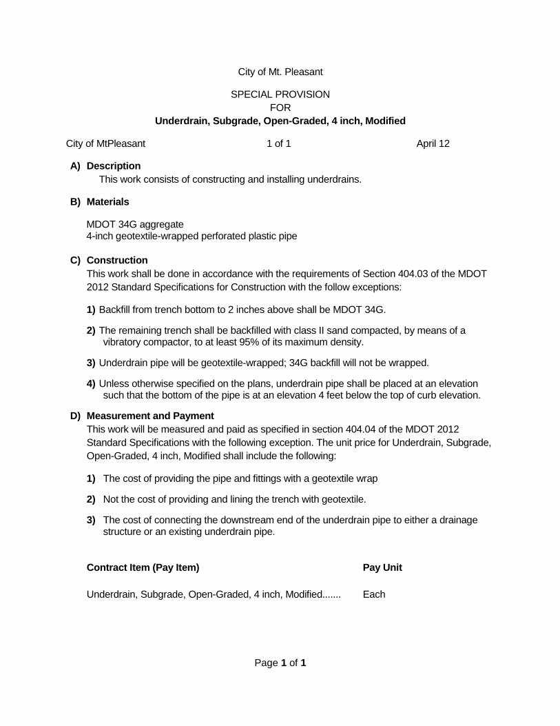
A) Description
This work consists of constructing and installing underdrains.
B) Materials
MDOT 34G aggregate 4-inch geotextile-wrapped perforated plastic pipe
C) Construction
This work shall be done in accordance with the requirements of Section 404.03 of the MDOT
2012 Standard Specifications for Construction with the follow exceptions:
1) Backfill from trench bottom to 2 inches above shall be MDOT 34G.
2) The remaining trench shall be backfilled with class II sand compacted, by means of a vibratory compactor, to at least 95% of its maximum density.
3) Underdrain pipe will be geotextile-wrapped; 34G backfill will not be wrapped.
4) Unless otherwise specified on the plans, underdrain pipe shall be placed at an elevation such that the bottom of the pipe is at an elevation 4 feet below the top of curb elevation.
D) Measurement and Payment
This work will be measured and paid as specified in section 404.04 of the MDOT 2012
Standard Specifications with the following exception. The unit price for Underdrain, Subgrade,
Open-Graded, 4 inch, Modified shall include the following:
1) The cost of providing the pipe and fittings with a geotextile wrap
2) Not the cost of providing and lining the trench with geotextile.
3) The cost of connecting the downstream end of the underdrain pipe to either a drainage structure or an existing underdrain pipe.
Contract Item (Pay Item) Pay Unit
Underdrain, Subgrade, Open-Graded, 4 inch, Modified....... Each

Page 1 of 14
City of Mt. Pleasant
SPECIAL PROVISION
FOR
WATER SYSTEM MATERIALS AND CONSTRUCTION
City of MtPleasant 1 of 14 April 12
A) Description
The Contractor shall furnish all labor, equipment, and materials to completely construct,
test, and place in operation, the water system as shown on the drawings and specified herein.
B) Materials
1) Water Main Pipe
i) Ductile Iron Pipe
Ductile iron pipe shall meet the requirements of ANSI/AWWA C151/A21.51. Where
these specifications differ with ANSI/AWWA C151/A21.51 these specifications will
prevail.
Cement Mortar Lining - Cement mortar lining of pipe shall conform to ANSI/AWWA
C104/A21.4. Care shall be taken to insure that no mortar remains in the joint surface
of the bell. If mortar is found in the joint surface or lining, of greater thickness than
allowed, the pipe will be returned.
Length of Pipe - The minimum nominal laying length of the pipe shall be eighteen feet
(18'). A maximum of twenty percent (20%) of the total number of each size of an order
may be furnished as much as twenty-four inches (24") shorter than the nominal laying
length; an additional ten percent (10%) may be furnished as much as six inches (6")
shorter than nominal laying length.
Pipe Thickness - Ductile iron pipe shall have a wall metal thickness as follows:
6-inch pipe 0.31 inch (Class 52)
8-inch pipe 0.33 inch (Class 52)
12-inch pipe 0.37 inch (Class 52)
16-inch pipe 0.37 inch (Class 51)
20-inch pipe 0.39 inch (Class 51)
Tolerances will be as allowed in ANSI/AWWA C151/A21.51. Pipe sizes not listed
above will not be approved for use as main lines in the City water system.
Coating - The inside and outside of the pipe shall be coated with a bituminous coating
of either coal-tar or asphalt base one mil. thick.

Page 2 of 14
Independent Tests - The supplier shall furnish reports of all tests and inspections as
required in the ANSI/AWWA C151/A21.51.
ii) Polyvinyl Chloride Pipe (PVC)
Polyvinyl chloride pipe (PVC) shall be of a class and designation as shown on the
proposal, Plans and/or special conditions, with a SDR of 18 to 13.5 and compound
designation Class No. 12454A, ASTM D-1784. PVC pipe shall be in accordance with
current AWWA Standard C-900 and blue in color.
PVC pipe sizes six to twelve inches (6" - 12") in diameter shall be Class 150, and pipe
sizes greater than twelve inches (12") shall be Class 200.
A single strand of 12 gauge insulated copper wire, blue in color, shall be buried in the
trench twelve inches (12") above the PVC pipe. Solder all wire splices and wrap with
"Scotch 2200 Vinyl Mastic Pads". The tracer wire shall be connected to each hydrant
at a bolt on the bottom of the hydrant barrel by use of a soldered connection, a
crimped U-shaped connection, or a ring lug.
iii) Restrained Joint PVC Pipe (RJPVC)
Restrained Joint PVC Pipe (RJPVC) shall use a Certa-LokTM or approved equal joint
restraint system. RJPVC shall meet the above requirements for Polyvinyl Chloride
Pipe accept that it shall be Class 235.
iv) Water Services
Allowable sizes are one inch, two inch, four inch (1", 2", 4"), or as specified for mains.
Service saddles are required at each service connection on water main.
Material for four inch (4") shall be ductile iron or polyvinyl chloride, as specified for
mains. Material for one inch (1") and two (2") shall be one of the following:
(1) Type K annealed seamless copper tubing conforming to ASTM B-88.
(2) One inch (1") shall be copper tube size, polyethylene (PE) water service pipe
meeting AWWA C901 specifications. Markings on the pipe shall be AWWA C901,
PE 3406, ASTM D-2737, dimension ratio SDR-9 brand name, date of
manufacture, nominal size, sizing type (i.e., copper tube Size (CTS)), pressure
rating 160 PSI at 73 1/2oF temperature, seal or (mark) of accuracy.
(3) Two inch (2") shall be copper tube size, polyethylene (PE) water service pipe
meeting AWWA C901 specifications. Markings on the pipe shall be AWWA C901,
PE 3406, ASTM D-2737, dimension ratio 7, brand name, date of manufacture,
nominal size, sizing type (i.e., copper tube size (CTS), pressure rating 200 PSI at
73 1/2oF temperature, seal or (mark) of accuracy.
v) Joints
Page 3 of 14
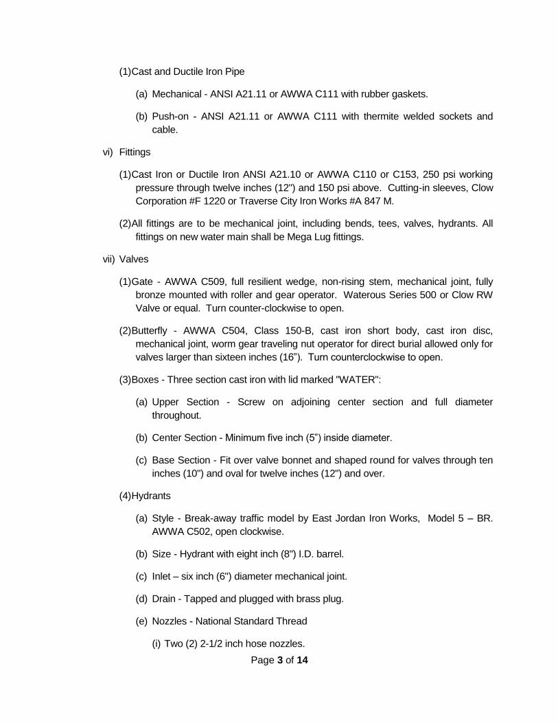
(1) Cast and Ductile Iron Pipe
(a) Mechanical - ANSI A21.11 or AWWA C111 with rubber gaskets.
(b) Push-on - ANSI A21.11 or AWWA C111 with thermite welded sockets and
cable.
vi) Fittings
(1) Cast Iron or Ductile Iron ANSI A21.10 or AWWA C110 or C153, 250 psi working
pressure through twelve inches (12") and 150 psi above. Cutting-in sleeves, Clow
Corporation #F 1220 or Traverse City Iron Works #A 847 M.
(2) All fittings are to be mechanical joint, including bends, tees, valves, hydrants. All
fittings on new water main shall be Mega Lug fittings.
vii) Valves
(1) Gate - AWWA C509, full resilient wedge, non-rising stem, mechanical joint, fully
bronze mounted with roller and gear operator. Waterous Series 500 or Clow RW
Valve or equal. Turn counter-clockwise to open.
(2) Butterfly - AWWA C504, Class 150-B, cast iron short body, cast iron disc,
mechanical joint, worm gear traveling nut operator for direct burial allowed only for
valves larger than sixteen inches (16”). Turn counterclockwise to open.
(3) Boxes - Three section cast iron with lid marked "WATER":
(a) Upper Section - Screw on adjoining center section and full diameter
throughout.
(b) Center Section - Minimum five inch (5”) inside diameter.
(c) Base Section - Fit over valve bonnet and shaped round for valves through ten
inches (10") and oval for twelve inches (12") and over.
(4) Hydrants
(a) Style - Break-away traffic model by East Jordan Iron Works, Model 5 – BR.
AWWA C502, open clockwise.
(b) Size - Hydrant with eight inch (8") I.D. barrel.
(c) Inlet – six inch (6") diameter mechanical joint.
(d) Drain - Tapped and plugged with brass plug.
(e) Nozzles - National Standard Thread
(i) Two (2) 2-1/2 inch hose nozzles.
Page 4 of 14
(ii) One (1) 4-1/2 inch pumper nozzle.
(f) Operating nut and nozzle cap nuts to be 1-3/4 inch square.
(g) Burial - six feet (6’) minimum or as directed on the Plans or by the Engineer.
The Contractor is to verify needed fire hydrant length to provide for 22 inch port
height above the ground.
(h) Conforming to City standards.
(5) Service Fittings
(a) Unions will not be allowed between corporation stop and the curb stop. New
services and the repair of existing services shall be made so that there will be
a continuous, unbroken pipe between the corporation stop and the curb stop.
(b) Service Saddles - Double-strap bronze or brass parts, AWWA CC threads.
For PVC C900 pipe, use Ford S90 or approved equivalent.
(c) Brass Corporation Stops [With CC (AWWA) threads]
(i) Ford - one inch (1") F600; Mueller – one inch (1") H15000 or approved
equivalent.
(ii) Polyethylene Pipe - Use above specified corporations with adapter. Ford C
06-44.
(iii) For two inch (2") Services - Ford FB 1000, Mueller P-25008
(d) Brass Curb Stops – two inch (2") Minneapolis pattern required.
(i) Ford Z22-333M, Z22-444M, Z44-777M, Mueller P25155 or approved
equivalent. Polyethylene pipe will require a Ford C 06-44 adapter or equal.
(e) Curb Stop Boxes - six feet (6’) burial – two inch (2") Minneapolis tapped base
with 1-1/4 inch upper section riser with pentagon brass nut in cap. Mueller
H10300, Ford type PL or approved equivalent.
(6) Miscellaneous
(a) Stainless Steel Tie Rods and Clamps - Clow Corp. or Traverse City Iron
Works.
(b) Plastic Seamless Encasement Tubing
(i) Material - ASTM D-1248 Polyethylene, Type III, Class C, eight (8) mils thick.
(ii) Closing Tape – two inches (2") wide Poly-Ken #900 or Scotchwrap #50.
(c) Tapping Sleeves

Page 5 of 14
(i) The tapping sleeve shall be a Ford Tapping sleeve, style FAST, with a
stainless steel flange and rubber coat.
(ii) Stainless steel tapping sleeve shall not be allowed on water mains larger
than 16 inches.
(iii) Full circle mechanical joint cast iron shall be required on water mains larger
than 16 inches.
(iv) All tapping sleeves must be pressure tested to 150 psi before main is
tapped.
(7) Shop Drawings and Material Inspection
(a) The Contractor shall have the City Water Department Superintendent review
shop drawings and all materials to be used on the City water system prior to
installation.
C) Construction
1) Water Main
The installation, handling, and storage of all pipe and appurtenances shall be according to
manufacturer's recommendations. Pipe shall, at all times, be protected against impact
shocks and free fall. Stockpiling of pipe and appurtenances at the site shall be in such a
location as to minimize handling and prevent collecting or submergence with water.
The depth of trench shall be such that the top of the pipe to be placed therein shall not be
less than six feet (6') or more than seven feet (7') below the proposed finish grade. The
depth shall be increased or decreased, if so shown on the Plans or so ordered by the
Engineer. Depths shall be noted on the "As Built" Plans and Daily Inspection Reports.
The trench shall be of such width as will readily permit the laying, handling and assembling
of the pipes in the trench and to allow thorough filling and compacting of the earth backfill,
adjacent to the lower half of the pipe. All hub holes shall be excavated to an extra width
and depth to allow for proper examining of the pipe and shall provide a solid bearing for
the pipe, practically its full length without refilling before the pipe is laid. Blocking of the
pipe will not be allowed.
The trench bottom shall be undercut three to four-inches (3”-4”) below the final location of
the pipe and the trench then filled with Class II sand or crushed stone compacted with
hand tampers to provide a cushion for bedding the pipe. The Contractor shall provide the
sand or crushed stone from off the site, except when the trench passes through well-
defined strata of sand or gravel.
Trenches for pipe shall be excavated so that there will be a minimum clearance of six
inches (6") on each side of the barrel of the pipe and a maximum width of trench at the
level of the top of the pipe, of not more than 16 inches greater than the OD of the pipe.

Page 6 of 14
There shall be, at all times, a sufficient width to permit the pipe to be laid and to permit
first-class construction methods to be used. Sufficient space shall be provided in the
trench to permit the joint to be properly made.
Excavation for structures shall be extended sufficiently beyond the limits of the structure to
provide ample room for placement and for other construction methods to be followed,
wherever necessary.
In case soft material is encountered in the bottom of a trench or underneath a special
structure, which, in the opinion of the Engineer, is not suitable for supporting the pipe or
structure, the Engineer may order the removal of this soft material and its replacement
with crushed stone, concrete or other material in order to make a suitable foundation for
the construction of the pipe or structure.
After the pipe is laid, Class II sand, fine gravel or crushed stone shall be placed the entire
width of the trench up to the spring line of the pipe. Backfill shall be carefully tamped
under the haunches of the pipe. Additional sand, gravel or stone shall then be placed until
the entire width of the trench is filled to not less than one foot (1’) above the top of the pipe.
Sand used for backfill around and over the pipe shall be thoroughly compacted with a
vibratory compactor; hand compaction will not be acceptable.
The remainder of the backfilling may be done with acceptable material. All backfill,
including pipe bedding, is to be compacted in maximum one-foot (1’) lifts to a density of 95
percent of the maximum unit weight as determined by the modified proctor.
After the trench has been excavated as required, the pipe, fittings, valves and hydrants
shall, after first being thoroughly inspected and the joints cleaned, be placed in the trench.
All pipe fittings, and valves that will not be chlorinated with the new water main, shall be
swabbed inside with five percent (5%) bleach (Sodium Hypochlorite) full strength before
assembly and placement into the system. All pipe, fittings, valves and hydrants shall be
carefully placed into the trench in such a manner as to prevent damage to them. Under no
circumstances shall water main materials be dropped or dumped into the trench.
All lumps, blisters, and excess tar coating shall be removed from the bell and spigot ends
of all ductile iron pipe and fittings. The outside of the spigot and the inside of the bell shall
be wire-brushed and wiped clean before the pipe is laid.
Any damage to the exterior coating of the pipe shall be repaired with an approved coating
before the pipe is laid. After placing a length of pipe in the trench, the spigot end shall be
lubricated and then entered into the bell and the pipe pushed to the stop mark and brought
to correct line and grade. Lubricants recommended by the pipe manufacturer and
approved for use on a potable water system shall be applied as recommended. Due care
should be used to seat the gasket evenly in the bell at all points.

Page 7 of 14
The plain end of the slip type joint is furnished with a slight taper to ease its sliding fit with
the gasket when the joint is made up. When necessary to cut pipe in the field, the outside
of the cut end should be tapered by filing or grinding back about 1/8-inch at an angle of
about 30 degrees with the centerline of the pipe.
Cutting pipe for inserting valves, fittings, etc., shall be performed in a neat workmanlike
manner, without damage to the pipe or lining, and so as to leave a smooth end at right
angles to the axis of the pipe.
Ductile Iron - Cutting shall be performed with a roller or shear type cutter for pipe sizes up
to 20 inches in diameter. When machine cutting is not available for cutting pipe twenty 20
inches in diameter, or larger, electric arc cutting method will be permitted, using a carbon
or steel rod. Only qualified, experienced workmen shall be used for this.
Asbestos-Cement or PVC Pipe - Cutting the pipe shall be performed by hand saw,
abrasive discs or with a special asbestos-cement or PVC pipe cutting tool. All piping
cutting tools must be of the true cutting variety. Under no circumstances is the pipe to be
cut with a roller or shear type cutting tool.
If the trench contains any water, the open ends of the pipe shall be plugged with a water
tight plug. A plug shall be used during any breaks in construction to prevent any
possible contamination.
Whenever it is desirable to deflect the pipe in order to form a long-radius curve or to avoid
obstructions, the pipe may be deflected within the tolerances recommended by the
manufacturer and approved by the Engineer. No deflections in excess of those
recommended by the manufacturer shall be allowed except by utilization of standard
fittings as specified herein.
i) Valve and Hydrant Operation
No valves or fire hydrants on the existing system or new system, after it is in operation
within the City system, shall be operated for any purpose by the Contractor without
prior permission of the City Water Superintendent. Any unauthorized operation of
said valves or fire hydrants shall result in a three hundred dollar ($300.00) fine per
incident.
ii) Notification Procedure for Scheduled Water main Shutdown
A 48 hour notification is required to the Water Department and to critical users, as
identified below, all others require a 24 hour notification. Notification must be in writing
stating the time of shutdown and length of time water is to be off. It shall be the
responsibility of the Contractor to notify, in writing, all persons affected by any shutoff
in accordance with the notification procedures.
Critical users are Central Michigan University, restaurants, beauty shops, hospitals,
medical care facilities, nursing homes, schools, and commercial laundries.

Page 8 of 14
iii) Shutdown of Water Mains
Water mains shall not be shutdown on Mondays, Saturdays, Sundays, or holidays,
and/or one (1) day on either side of the holiday unless approved in advance by the
Director of Public Works or Water Superintendent. From Tuesday through Friday,
water mains shall be shutdown after 9:00 a.m. and are to be placed back into service
before 4:30 p.m., after notification specified in the preceding paragraph. Notification
must also be given to the City Water Superintendent and the Fire Department. The
City has a water main shutdown procedure and checklist which are part of this
specification by reference.
2) Valve Manholes
Valves twenty 20 inches or larger shall be installed in a valve manhole. All air release
valves shall be in manholes. Details and materials of construction shall be as shown on
the Plans and as specified for sanitary sewer manholes. The cover shall have "WATER"
cast in the top.
3) Setting Valves and Boxes
All valves shall be set at a depth to the top of pipe, from a minimum of six feet (6') to a
maximum of seven feet (7') below finished grade, with the stem in a vertical position and
shall be plumb. The valve box shall be set so that it will not transmit shock or stress to the
valve. It shall be centered over the stem nut of the valve and shall be true and plumb.
The box shall be adjusted so that the cover is flush with the finished ground surface or as
directed by the Engineer. Unless otherwise specified, a valve box shall be provided for
every valve.
4) Setting Fire Hydrants
Fire hydrants shall be located as shown on the Plans, or as directed by the Engineer. All
hydrants shall be set plumb and to a grade which will place center of the pumper nozzle
above finished grade, (E.J.I.W. 22" above finished grade), unless otherwise directed by
the Engineer. At no time shall the breakaway flange be below finished grade. Sufficient
barrel extensions shall be furnished and installed by the Contractor to meet this
requirement. Barrel extensions shall be installed such that the breakaway flange is
located at finished grade level. Barrel extensions, if needed, shall be incidental to
construction.
Each hydrant shall be connected to the main by a six inch (6") branch. A six inch (6")
resilient wedge gate valve with box shall be installed with a valve depth of six feet (6’)
minimum to seven (7') feet maximum from finished grade to top of pipe, in each hydrant
connection. The hydrant and valve shall be connected to the main line tee, as shown in
the City standard detail, and the steamer port on the hydrant shall face the roadside.
5) Blocking

Page 9 of 14
All bends, stub ends, plugs and any other portion of the system, which may be subject to
separation of joints because of water pressure, shall be securely braced or blocked.
Blocking shall be concrete blocks or concrete poured in place and shall be so placed as to
prevent any movement of pipe or fitting joints due to water pressure. Shape of blocks
shall be in accordance with the details shown on the Plans and within the following sizes:
Bearing Area in Square Feet Against Trench Wall in Sand
Pipe Tees Hydrants 45 22-1/2 11-1/4
Size Plugs 90 deg. Els deg. Els deg. Els deg. Els
______________________________________________________________________
4" 2 2 1 1 1
6" 3 3 2 1 1
8" 4 6 3 2 1
10" 7 9 5 3 2
12" 9 11 6 3 2
14" 11 15 8 5 3
16" 13 20 10 6 3
18" 16 25 12 7 4
20" 20 28 14 8 4
24" 28 40 20 11 6
OTHER SOIL CONDITIONS:
Cemented Sand or Hardpan Multiply above by 0.5
Gravel Multiply above by 0.7
Hard Dry Clay Multiply above by 0.7
Soft Clay Multiply above by 2.0
Muck - secure all fittings with tie rod clamps with concrete reaction backing, the same as
listed for sand conditions.
6) Water Service Connection
i) Water service connections shall not be made prior to the water main passing the
bacteriological tests.
ii) Water service materials must meet City specifications and be one inch (1") in size,
unless specified otherwise.
iii) Each service will consist of a saddle, corporation, piping, curb stop, and curb box.
iv) Depth shall be a minimum of six feet (6') and a maximum of seven feet (7') of cover to
the finished grade of the project or development.

Page 10 of 14
v) Curb boxes shall be adjusted to finished grade.
vi) Curb boxes shall be fully screwed onto the curb stop valve.
vii) Pipe must be beveled and lubricated with an approved lubricant for use on potable
water systems.
viii) Curb stops are to be installed so that the key top is parallel to curb, or proposed curb,
when in the off position. (i.e. Flow is to be perpendicular to curb.) Curb boxes
installed in concrete or bituminous areas shall be separated from the concrete of
bituminous by the use of a length of four inches (4”) PVC pipe.
ix) The Contractor will check to see if existing curb stop is in the on or off position and
leave new curb stop in same position. No curb stop valve will be turned on unless
there is someone in the building to ensure there are no leaks
x) Water services, if extended past the curb stop, shall be extended straight for a
minimum of six feet (6') or past the right-of-way line perpendicular to the curb or
proposed curbline.
xi) Services are to be flushed prior to backfilling.
xii) Taps are to be on the service side of the main.
xiii) Taps shall be horizontal to five degrees above horizontal.
xiv) Cookies must be given to the inspector at the time of tap.
7) Water Service Reconnections
i) The City Water Department shall be notified of any iron pipe or lead pipe water
services in use (pressurized).
ii) Except for iron or lead pipes, all reconnections shall be of the same materials as the
existing service and use brass fittings.
iii) Where iron pipe or lead pipe water services are encountered, a new one inch (1")
water service connection shall be constructed, in accordance with Sec. 8.03F, Water
Service Connection above.
iv) Reconnection shall include service saddle, corporation, and piping meeting City
specifications.
v) Taps shall be on the service side of the main.
vi) Taps shall be horizontal to 5 degrees above horizontal. .
vii) After reconnection is made and before the service line is pressurized, the water meter
shall be removed, the line flushed, and the meter reinstalled. Any stopped water

Page 11 of 14
meters caused by reconnection will be charged to the Contractor on a time and
material basis for repair and re-installation.
8) Live Taps
All service taps shall be made live taps, including chlorination and testing taps.
D) Testing and Sterilization
1) Pressure Testing
The Contractor shall furnish equipment for the test, and the test shall be run by him under
the direction of the Engineer. The test shall be made at 150 pounds per square inch
hydrostatic pressure, and shall be maintained for at least two (2) hours and the leakage
shall not exceed 10.45 gallons per day, per inch diameter, per mile of pipe. The City will
provide a certified gauge for the test. The Contractor shall furnish all labor and all
additional equipment to make the test.
All valves shall be opened such that all air in the line can be removed upon filling with
water. The Contractor shall install any corporation stops necessary to allow the air to be
expelled. The main shall be filled at a velocity no greater than 1 foot per second. Flushing
at a minimum velocity of 3 feet per second shall be preformed prior to starting any
pressure testing.
The Contractor shall run a preliminary test to determine that all air has been expelled and
to check for any leakage. If any leakage should exist, the Contractor shall make the
necessary repairs and perform the preliminary testing until satisfactory results are
obtained. The final test shall be made in the presence of the Engineer or Water
Superintendent. If the test to be witnessed by the Engineer or Water Superintendent fails,
the Contractor will be billed $75.00 per hour with a $150.00 minimum for the additional
testing. The City will provide a certified gauge for the pressure test. The Contractor shall
provide any additional equipment necessary to add and measure the water necessary to
maintain the hydrostatic pressure within five pounds per square inch (5 psi) of the required
test pressure for the duration of the test. If the City’s gauge becomes damaged while in
the Contractor’s possession, the Contractor will be charged for the repair/replacement of
the gauge.
When the testing period is complete, the Contractor shall add and measure the water to
bring the final pressure reading to the initial pressure reading. The total gallons added
during the duration of the test shall not exceed the allowable leakage.
2) Sterilization
Before the mains are chlorinated, they shall be thoroughly flushed. All mains shall be
chlorinated for a period of twenty-four (24) hours. The Contractor shall furnish all
necessary equipment and materials and the work shall be done under the direction of the
City Engineer in accordance with all local and state health department regulations.

Page 12 of 14
Chlorine shall be added in sufficient quantity to give a 50 PPM residual of free chlorine
after a twenty-four (24) hour period. Chlorine tablets shall not be used.
After completion of the chlorine procedure, the main shall be flushed and sampled, as per
Michigan Department of Public Health requirements. Samples shall be taken from each
end of the main with additional samples taken in order to maintain a minium of 1 sample
for each 1,200 feet of main. Sample shall also be taken at the end of each branch
installed. The chlorinated water flushed from the main shall not be discharged to a storm
sewer or open drainage way, that would result in discharge to surface water. The
chlorinated water must be discharged to a sanitary sewer, held on site, or treated, until the
chlorine is removed. All requirements of the Federal Clean Water Act (CWA) must be
followed.
Two consecutive samples of water, 24 hours apart, shall be taken from the main by the
Water Department for bacteriological tests, at a rate established by the DPW, per test. If
the results of these tests indicate safe water, the main may be placed in service. If the
tests should result in unsafe conditions, the chlorination shall be repeated by the
Contractor. The Contractor shall be responsible for all costs associated with necessary
retesting.
E) Measurement and Payment
1) Water Main, ___ inch
i) Description
The work of Water Main, ___ inch, Modified shall consist of excavation, the furnishing
and placing of the complete water main (including all fittings, testing, concrete work,
disinfecting, backfilling and removal of surplus excavated material), protection and
replacement or repair of existing utilities and restoration of the surface to within four
inches (4”) of original grade. All work shall be done in accordance with the Plans
and/or Specifications.
ii) Method of Measurement and Basis of Payment
Water Main, ___ inch, Modified will be measured in place by length in feet and will be
paid for at the contract unit price which price shall be payment in full for any fittings,
couplers, sheeting or shoring trench walls, backfill as required and all labor, material
and equipment needed to accomplish this work.
2) Water Valve ___inch
i) Description
The work of Water Valve ___ inch, shall consist of excavation, the furnishing and
placing of valves, valve manholes (inc. castings), and/or boxes, as applicable. All work
shall be done in accordance with the Plans and/or Specifications.
Page 13 of 14
ii) Method of Measurement and Basis of Payment
Water Valve ___ inch, will be paid for by the unit each, and shall include the valve box
and/or valve manhole, and casting, as well as all labor, materials, and related work as
described above.
3) Hydrant Set
i) Description
The work of Hydrant Set shall consist of furnishing and installing fire hydrant, an
auxiliary valve, valve box, connecting piping, fittings, thrust block, barrel extension,
drainage pit, and miscellaneous appurtenances. All work shall be done in accordance
with the Plans and/or Specifications.
ii) Method of Measurement and Basis of Payment
Hydrant Set shall be paid for by the unit each, and shall include the auxiliary valve,
valve box, connecting piping, fittings, thrust block, barrel extension, and miscellaneous
appurtenances. All work shall be done in accordance with the Plans and/or
Specifications.
4) Tapping Sleeve & Valve ___ inch by ___ inch
i) Description
The work of Tapping Sleeve & Valve ___ inch by ___ inch, shall consist of furnishing
and installing tapping sleeves and valves on existing mains without loss of pressure in
the existing main. It shall also include the installation of a valve box or manhole, as
applicable. All work shall be done in accordance with the Plans and/or Specifications.
ii) Method of Measurement and Basis of Payment
Tapping Sleeve & Valve ___ inch by ___ inch shall be paid for by the unit each, and
shall include the installation of a valve box or manhole, as applicable. There will be a
time and materials charge by the City if main has to be de-pressurized to pull out
cookie.
5) Water Service - (Short or Long), ___inch
i) Description
The work of Water Service - (Short or Long), ___inch, shall consist of excavation,
furnishing and placement of sand backfill, removal of surplus excavated material,
tapping the main, furnishing and installation of service clamp or saddle, corporation
stops, curb stops, curb boxes, service pipe, and fittings to connect to existing service
pipe, in accordance with the Specifications. Long-side service leads shall include
crossing roads. Short-side service leads are those which do not cross roads.

Page 14 of 14
ii) Method of Measurement and Basis of Payment
Water Service - (Short or Long), ___inch, shall be paid for by the unit each, and shall
include tapping the main, furnishing and installation of service clamp or saddle,
corporation stops, curb stops, curb boxes, service pipe, and fittings to connect to
existing service pipe, in accordance with the Specifications.
6) Water Service Reconnection ___ inch
i) Description
The work of Water Service Reconnection ___ inch, shall consist of excavation,
furnishing and placement of sand backfill, removal of surplus excavated material,
tapping the main, furnishing and installation of service clamp or saddle, corporation
stops, service pipe from the main to the reconnection point between the main and
the existing curb stop box, and fittings to connect to existing service pipe, in
accordance with the Specifications.
ii) Method of Measurement and Basis of Payment
Water Service Reconnection ___ inch, shall be paid for by the unit each, and shall
include tapping the main, furnishing and installation of service clamp or saddle,
corporation stops, service pipe, and fittings to connect to existing service pipe, in
accordance with the Specifications
Contract Item (Pay Item) Pay Unit
Water Main, ___ inch......................................................... Linear Foot
Water Valve ___inch.......................................................... Each
Hydrant Set........................................................................ Each
Tapping Sleeve & Valve ___ inch by ___ inch.................. Each
Water Service - (Short or Long), ___inch.......................... Each
Water Service Reconnection ___ inch............................... Each