standards, formulae, tables
TRANSCRIPT
Eaton Wiring Manual 06/11
10-1
1010
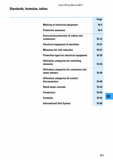
Standards, formulae, tables
Page
Marking of electrical equipment 10-2
Protective measures 10-4
Overcurrent protection of cables and
conductors 10-12
Electrical equipment of machines 10-21
Measures for risk reduction 10-27
Protection types for electrical equipment 10-29
Utilization categories for switching
elements 10-34
Utilization categories for contactors and
motor starters 10-36
Utilization categories for switch-
disconnectors 10-40
Rated motor currents 10-43
Conductors 10-46
Formulae 10-54
International Unit System 10-58

Eaton Wiring Manual 06/11
10-2
Standards, formulae, tables
1010
Marking of electrical equipment
Marking to DIN EN 81346-2 (IEC 81346-2)
Eaton uses the above standard.
Unlike the method of marking up to now, the function of the electrical equipment in the respective circuit primarly determines the cose letter. This means that there is some freedom in the selection of the code letters.
Example of a resistor
• Normal current limiter: R
• Heater resistor: E
• Measurement resistor: B
In addition to that, Eaton specific decisions have been made with regard to the interpretation of the standard that sometimes deviate from the standard.
• The marking of connection terminals are not readable from the right.
• A second code letter for the marking of the use of the equipment is not given,e.g.: timing relay K1T becomes K1.
• Circuit-breakers with the main function of protection are still marked with Q.They are numbered from 1 to 10 from the top left.
• Contactors are newly marked with Q and numbered from 11 to nn. e.g.: K91M becomes Q21.
• Contactor relays remain K and are numbered from 1 to n.
The marking appears in a suitable position as close as possible to the circuit symbol. The marking forms the link between the equipment in the installation and the various circuit documents (wiring diagrams, parts lists, circuit diagrams, instructions). For simpler maintenance, the complete marking or part of it, can be affixed on or near to the equipment.
Selected equipment with a comparison of the Eaton used code letters old – new → Table, page 10-3

Standards, formulae, tablesMarking of electrical equipment
Eaton Wiring Manual 06/11
10-3
1010
Code letter Purpose Examples for electrical equipment
A (several purposes) (without main purpose)
B Signal generation Pressure switches; limit switches
C Storage Capacitors
D (reserved for later)
E Energy supply Heating resistor, lamps
F Protection Bimetal releases, fuses
G Power supply Generator, UPS
H (reserved for later)
I (must not be used)
J (reserved for later)
KP Signal processing Contactor relay, timing relays
L (reserved for later)
M Drive energy Motor
N (reserved for later)
O (must not be used)
P Information display Signalling and measuring devices
Q Switching energy / signal flow
Soft starter, contactor, motor starter
R Energy flow limitation Reactor coils, diodes
S Manual signal generation Control circuit devices
T Energy conversion Frequency inverters, transformer
U Object fixing
V Material processing Electro filter
W Power transmission
X Object connection Terminal, plug connector
Y, Z (reserved for later)
Eaton Wiring Manual 06/11
10-4
Standards, formulae, tables
1010
Protective measures
Protection against electrical shock to IEC 60364-4-41/DIN VDE 0100-410
This is divided into basic protection (previously protection against direct contact), fault protection (previously protection against indirect contact) and protection against both direct and indirect contact.
• Basic protection
These are all the measures for the protection of personnel and working animals from dangers which may arise from contact with live parts of electrical equipment.
• Fault protection
This is the protection of personnel and working animals from fault scenarios which may arise from accidental contact with components or extraneous conductive parts.
• Additional protection
If basic or fault protection fails or there is a greater potential danger, residual current protective devices with IΔn ≦ 30 mA offer additional protection.
Protection must be ensured by either a) the equipment itself or b) the use of protective measures when erecting the installation or c) a combination of a) and b).
If basic, fault and additional protection is combined in a suitable manner the following protective measures result and are covered in section 410 of DIN VDE 0100:
• Automatic disconnection of the power supply (0100-411)
• Double or reinforced insulation (0100-412)
• Protective separation (0100-413)
• Safety extra low voltage SELV or PELV (0100-414)
One of the key amendments to DIN VDE 0100-410 of June 2007 was the additional protection for final circuits for outdoor areas and sockets (411.3.3). This stipulates that an additional protection must be provided by means of residual current devices (RCDs) with IΔn ≦ 30 mA for sockets ≦ 20 A, as well as final current circuits for portable equipment ≦ 32 A used outdoors. The previous recommendation has therefore been changed to a mandatory requirement in order to increase safety.

Standards, formulae, tablesProtective measures
Eaton Wiring Manual 06/11
10-5
1010
Protection against indirect contact by means of disconnection or indication
The conditions for disconnection are determined by the type of system in use and the protective device selected.
Systems to IEC 60364-1/DIN VDE 0100-100
RB Earthing on the current sourceRA Earthing on chassis of electrical
equipment
Earth continuity type systems Meaning of designation
TN system
T: Direct earthing of a pointN: Chassis (of electrical equipment)
directly connected with the power supply system earth
TT system
T: Direct earthing of a pointT: Direct electrical connection of chassis
to earth, independent of any existing earthing of the power supply system
IT system
I: All live parts isolated from earth or one point connected to earth via a high impedance
T: Direct electrical connection of chassis to earth, independent of any existing earthing of the power supply system
L2
N
L1
L3
PE
RB
L2
N
L1
L3
RB RA
L2L1
L3
RA
Standards, formulae, tablesProtective measures
Eaton Wiring Manual 06/11
10-6
1010
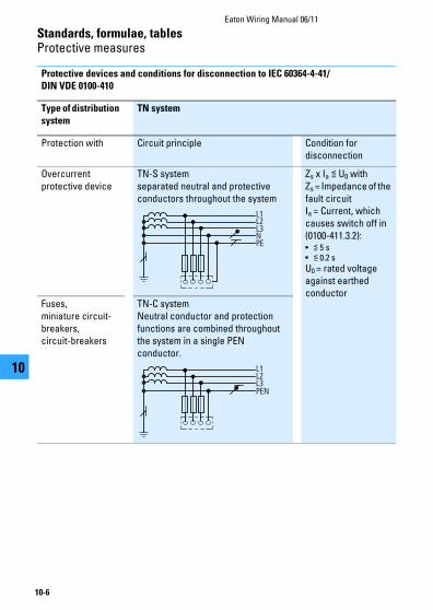
Protective devices and conditions for disconnection to IEC 60364-4-41/
DIN VDE 0100-410
Type of distribution
system
TN system
Protection with Circuit principle Condition for disconnection
Overcurrent protective device
TN-S systemseparated neutral and protective conductors throughout the system
Zs x Ia ≦ U0 withZs = Impedance of the fault circuitIa = Current, which causes switch off in (0100-411.3.2):• ≦ 5 s• ≦ 0.2 s
U0 = rated voltage against earthed conductor
Fuses,miniature circuit-breakers,circuit-breakers
TN-C systemNeutral conductor and protection functions are combined throughout the system in a single PEN conductor.
L2
N
L1
L3
PE
L2
PEN
L1
L3

Standards, formulae, tablesProtective measures
Eaton Wiring Manual 06/11
10-7
1010
Protective devices and conditions for disconnection to IEC 60364-4-41/DIN VDE 0100-
410
1) → Table, page 10-11
Type of distribution
system
TN system
Protection with Circuit principle Condition for disconnection
Overcurrent protective device
TN-C-S systemNeutral conductor and protective conductor functions are in a part of the system combined in a single PEN conductor.
Fault current protective device
Zs x IΔn ≦ U0 withIΔn = Rated fault currentU0 = Maximum permissible touch voltage1):(≦ 50 V AC, ≦ 120 V DC)
L2L1
L3NPE(N)
L2L1
L3NPE(N)
Standards, formulae, tablesProtective measures
Eaton Wiring Manual 06/11
10-8
1010
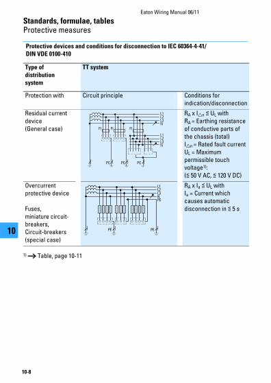
Protective devices and conditions for disconnection to IEC 60364-4-41/
DIN VDE 0100-410
1) → Table, page 10-11
Type of
distribution
system
TT system
Protection with Circuit principle Conditions for indication/disconnection
Residual current device(General case)
RA x IΔn ≦ UL withRA = Earthing resistance of conductive parts of the chassis (total)IΔn = Rated fault currentUL = Maximum permissible touch voltage1):(≦ 50 V AC, ≦ 120 V DC)
Overcurrent protective device
Fuses,miniature circuit-breakers,Circuit-breakers (special case)
RA x Ia ≦ UL withIa = Current which causes automatic disconnection in ≦ 5 s
L2
PE
L1
L3N
L2L1
L3N
PE PE
FI FI FI
L2
PE
L1
L3NPE
PE
Standards, formulae, tablesProtective measures
Eaton Wiring Manual 06/11
10-9
1010
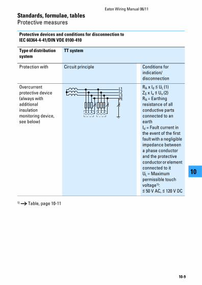
Protective devices and conditions for disconnection to
IEC 60364-4-41/DIN VDE 0100-410
1) → Table, page 10-11
Type of distribution
system
TT system
Protection with Circuit principle Conditions for indication/disconnection
Overcurrent protective device (always with additional insulation monitoring device, see below)
RA x Id ≦ UL (1)ZS x Ia ≦ Uo (2)RA = Earthing resistance of all conductive parts connected to an earthId = Fault current in the event of the first fault with a negligible impedance between a phase conductor and the protective conductor or element connected to itUL = Maximum permissible touch voltage1):≦ 50 V AC, ≦ 120 V DC
L2
PE
L1
L3
Standards, formulae, tablesProtective measures
Eaton Wiring Manual 06/11
10-10
1010
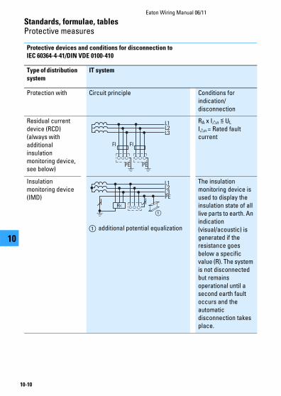
Protective devices and conditions for disconnection to
IEC 60364-4-41/DIN VDE 0100-410
Type of distribution
system
IT system
Protection with Circuit principle Conditions for indication/disconnection
Residual current device (RCD) (always with additional insulation monitoring device, see below)
RA x IΔn ≦ UL
IΔn = Rated fault current
Insulation monitoring device (IMD)
① additional potential equalization
The insulation monitoring device is used to display the insulation state of all live parts to earth. An indication (visual/acoustic) is generated if the resistance goes below a specific value (R). The system is not disconnected but remains operational until a second earth fault occurs and the automatic disconnection takes place.
L2
PE
L1
L3
PE
FI FI
L2
PE
L1
L3
R<
①

Standards, formulae, tablesProtective measures
Eaton Wiring Manual 06/11
10-11
1010
The protective device must automatically disconnect the faulty part of the installation. At no part of the installation
may there be a touch voltage or an effective duration greater than that specified in the table below.
Maximum disconnection times (s) as a function of the rated voltage.
Phase conductors to earth and the system in accordance with VDE 0100-411.3.2.2
U0 is the rated operating voltage phase conductor to earth.
Note:
A disconnection may be necessary for different reasons than the protection from electric shock.
System
TN
Max. permissible disconnection time [s]
DD
Max. permissible disconnection time [s]
50 V < U0 ≦ 120 V AC 0.8 0.3
DC (see note) (see note)
120 V < U0 ≦ 230 V AC 0.4 0.2
DC 5.0 0.4
230 V < U0 ≦ 400 V AC 0.2 0.07
DC 0.4 0.2
U0 > 400 V AC 0.1 0.04
DC 0.1 0.1

Eaton Wiring Manual 06/11
10-12
Standards, formulae, tables
1010
Overcurrent protection of cables and conductors
Cables and conductors must be protected by means of overcurrent protective devices against excessive temperature rises, which may result both from operational overloading and from short-
circuit. (in depth explanations on new DIN VDE 0100-430 contained in volume 143, 3rd edition, of the VDE publication series).
Overload protection
Overload protection involves the provision of protective devices which will interrupt overload currents in the conductors of a circuit before they can cause temperature rises which may damage the conductor insulation, the terminals and connections or the area around the conductors.
For the protection of conductors against overload the following conditions must be fulfilled (source: DIN VDE 0100-430)
IB Anticipated operating current of the circuit
IZ Current carrying capacity of conductor or cable
In Rated operational current of the protective device
Remark:
For adjustable protective devices,
In corresponds to the value set.
I2 The current which causes tripping of the protective device under the conditions specified in the equipment regulations.
Arrangement of overload protective
devices
Protection devices for overload protection must be fitted at the start of every circuit
and at every point where the current carrying capacity is reduced unless an upstream protection device can ensure protection.
IB ≦ In ≦ IZ
I2 ≦ 1.45 IZ
IA
1.45 3 Iz
Characteristic valuesof the protective device
Reference values of the cable
Rated curre
nt or
setti
ng current I n
Tripping curre
nt I 2
Current carrying capacity Iz
Operating current IB
Standards, formulae, tablesOvercurrent protection of cables and conductors
Eaton Wiring Manual 06/11
10-13
1010
Note:
Reasons for the current carrying capacity being reduced:
Reduction of the conductor cross-section, a different installation method, different conductor insulation, a different number of conductors.
Protective devices for overload protection should not be fitted if interruption of the circuit could prove hazardous. The circuits must be laid out in such a way that no
possibility of overload currents occurring need be considered.
Examples: Timing relay = function relay with contacts and coils Time switch = function relay with contacts
• Energizing circuits for rotating machines
• Feeder circuits of solenoids
• Secondary circuits of current transformers
• Circuits for safety purposes
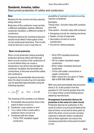
Short-circuit protection
Short-circuit protection means providing protective devices which will interrupt short-circuit currents in the conductors of a circuit before they can cause a temperature rise which may damage the conductor insulation, the terminals and connections, or the area around the cables and conductors.
In general, the permissible disconnection time t for short circuits of up to 5 s duration can be specified approximately using the following equation:
or
The meaning of the symbols is as follows:
t: Permissible disconnection time in the event of short-circuit in s
S: Conductor cross-section in mm2 I: r.m.s. value of the current with a
maximum short-circuit in Ak: Constants with the values
– 115 for PVC-insulated copper conductors
– 76 for PVC-insulated aluminum conductors
– 141 for rubber-insulated copper conductors
– 93 for rubber-insulated aluminum conductors
– 115 for soft-solder connections in copper conductors
– Other values for k are given in Table 43A of DIN VDE 0100-430.
With very short permissible disconnection times (< 0.1 s) the product from the equation k2 x S2 must be greater than the I2 x t value of the current-limiting device stated by manufacturer.
Arrangement of protective devices for
protection in the event of a short-circuit.
Protective devices for protection in the event of a short-circuit must be fitted at the start of every circuit and at every point at which the short-circuit current-carrying capacity is reduced unless a protective device fitted upstream can ensure the necessary protection in the event of a short circuit.
t k xSI---
2
= I2 x t = k2 x S2
Standards, formulae, tablesOvercurrent protection of cables and conductors
Eaton Wiring Manual 06/11
10-14
1010
Note:
Reasons for the reduction in the short-circuit current-carrying capacity can be: Reduction of the conductor cross-section, other conductor insulation.
Short-circuit protection must not be provided where an interruption of the
circuit could prove hazardous. In these cases two requirements must be fulfilled:
• The cable must be laid so that the risk of short-circuits is reduced to a minimum.
• The cable must not be laid in the vicinity of flammable materials.
Protection of the main poles and the neutral conductors
Protection of the main poles
Overcurrent protection devices must be provided in every main pole: they must disconnect the conductor in which the overcurrent occurs, but not necessarily also disconnect the other live conductors.
Note:
Where the disconnection of an individual main pole could prove hazardous, as for example, with three-phase motors, suitable precautions must be taken. Motor-protective circuit-breakers and circuit-breakers disconnect in 3 poles as standard.
Protection of the neutral conductor:
1. In installations with a directly earthed neutral point (TN or TT systems)
Where the cross-section of the neutral conductor is less than that of the main poles, an overcurrent monitoring device appropriate to its cross-section is to be provided in the neutral conductor; this overcurrent monitoring device must result in the disconnection of the phase conductors but not necessarily that of the neutral conductor.
An overcurrent monitoring device in the neutral conductor is not necessary where:
• the neutral conductor is protected in the event of a short-circuit by the protective device for the main poles
• the largest current which can flow through the neutral conductor is, in normal operation, considerably less than the current carrying capacity of this conductor.
Note:
This second condition is met provided that the power transferred is divided as evenly as possible among the main poles, for example where the total power consumption of the load connected between phase and neutral conductors, lamps and socket outlets is much less than the total power transferred via the circuit.
Standards, formulae, tablesOvercurrent protection of cables and conductors
Eaton Wiring Manual 06/11
10-15
1010
2.In installations without a directly earthed neutral point (IT system)
Where it is necessary for the neutral conductor to be included, an overcurrent monitoring device must be provided in the neutral conductor of each circuit, to cause disconnection of all live conductors in the relevant circuit (including the neutral conductor).
The overcurrent monitoring device may however be omitted where the neutral conductor in question is protected against short-circuit by an upstream protective device, such as in the incoming unit of the installation.
Disconnection of the neutral conductor
Where disconnection of the neutral conductor is specified, the protective device used must be designed in such a way that the neutral conductor cannot under any circumstances be disconnected before the phase conductors and reconnected again after them. 4-pole NZM circuit-breakers always meet these conditions.

Standards, formulae, tablesOvercurrent protection of cables and conductors
Eaton Wiring Manual 06/11
10-16
1010
Cu
rre
nt c
arr
yin
g c
ap
ac
ity
an
d p
rote
cti
on
of c
ab
les
an
d c
on
du
cto
rs w
ith
PV
C
insu
lati
on
to
DIN
VD
E 0
298-
4, a
t 25
°C a
mb
ien
t a
ir t
em
pe
ratu
re
Type
of c
able
or
cond
ucto
rN
YM, N
YBU
Y, N
HYR
UZY
, NYI
F,H
07V
-U, H
07V
-R, H
07V
-K, N
YIFY
NY
Y, N
YC
WY
, NY
KY,
NYM
, N
YMZ,
NYM
T, N
YBU
Y,
NH
YR
UZ
Y
Type
of
inst
alla
tion
A1
b1m
2C
E
In h
eat-
insu
latin
g w
alls
, in
cabl
e co
ndui
t un
der
the
surf
ace
In c
able
con
duit
s O
n a
wal
lEx
pose
d
Sin
gle-
core
ca
bles
Mul
ti-co
re c
able
Mul
ti-co
re c
able
un
der
the
surf
ace
Cab
le c
ores
in
cabl
e co
ndui
t on
the
wal
l
Mul
ti-co
re c
able
in
cab
le c
on
du
it o
n th
e
wal
l sur
face
Sin
gle
or m
ulti-
core
ca
bles
or
insu
late
d ca
bles
Mu
lti-
co
re c
ab
les
or
insu
late
d c
ab
les
wit
h a
m
inim
um
cle
ara
nc
e o
f 0.
3x
dia
me
ter
d t
o w
all
Num
ber
of
23
23
23
23
23
Cur
rent
-car
ryin
g ca
paci
ty I
z in
A fo
r 25
°C
ambi
ent a
ir te
mpe
ratu
re a
nd 7
0°C
ope
ratin
g te
mpe
ratu
re.
≧ 0
.3 d
≧ 0
.3 d
dd

Standards, formulae, tablesOvercurrent protection of cables and conductors
Eaton Wiring Manual 06/11
10-17
1010
Co
nti
nu
ed
Typ
e o
f in
stal
latio
nA
1b1
m2
CE
Num
ber
of
core
s2
32
32
32
32
3
Co
pp
er
cond
ucto
r cr
oss-
sect
ion
in
mm
2
I zI n
I zI n
I zI n
I zI n
I zI n
I zI n
I zI n
I zI n
I zI n
I zI n
1.5
16.5
1614
.513
18.5
1616
.516
17.5
1616
1321
2018
.516
2320
19.5
16
2.5
2120
19.5
1625
2522
2024
2021
2029
2525
2532
3227
25
428
2525
2534
3230
2532
2529
2538
3534
3242
4036
35
636
3533
3243
4038
3540
3536
3549
4043
4054
5046
40
1049
4045
4060
5053
5055
5049
5067
6360
6374
6364
63
1665
6359
5081
8072
6373
6366
6390
8081
8010
010
085
80
2585
8077
6310
710
094
8095
8085
8011
910
010
210
012
612
510
710
0
3510
510
094
8013
312
511
710
011
810
010
510
014
612
512
612
515
712
513
412
5
5012
612
511
410
016
016
014
212
514
112
512
512
517
816
015
312
519
116
016
216
0
7016
016
014
412
520
420
018
116
017
816
015
812
522
622
419
516
024
622
420
820
0
9519
316
017
416
024
622
421
920
021
320
019
016
027
325
023
622
429
925
025
225
0
120
223
200
199
160
285
250
253
250
246
224
218
200
317
315
275
250
348
315
293
250
For
over
curr
ent p
rote
ctiv
e de
vice
s w
ith a
rat
ed o
pera
tiona
l cur
rent
I n th
at d
oes
not c
onfo
rm to
the
valu
es g
iven
in th
e ta
ble,
sel
ect t
he n
ext l
ower
av
aila
ble
rate
d op
erat
iona
l cur
rent
val
ue.
Standards, formulae, tablesOvercurrent protection of cables and conductors
Eaton Wiring Manual 06/11
10-18
1010
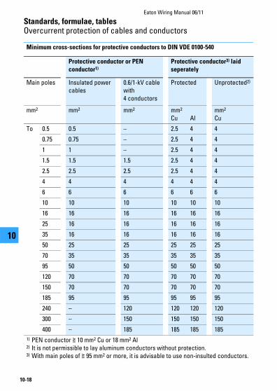
Minimum cross-sections for protective conductors to DIN VDE 0100-540
Protective conductor or PEN
conductor1)
Protective conductor3) laid
seperately
Main poles Insulated power cables
0.6/1-kV cable with 4 conductors
Protected Unprotected2)
mm2 mm2 mm2 mm2 Cu Al
mm2 Cu
To 0.5 0.5 – 2.5 4 4
0.75 0.75 – 2.5 4 4
1 1 – 2.5 4 4
1.5 1.5 1.5 2.5 4 4
2.5 2.5 2.5 2.5 4 4
4 4 4 4 4 4
6 6 6 6 6 6
10 10 10 10 10 10
16 16 16 16 16 16
25 16 16 16 16 16
35 16 16 16 16 16
50 25 25 25 25 25
70 35 35 35 35 35
95 50 50 50 50 50
120 70 70 70 70 70
150 70 70 70 70 70
185 95 95 95 95 95
240 – 120 120 120 120
300 – 150 150 150 150
400 – 185 185 185 185
1) PEN conductor ≧ 10 mm2 Cu or 18 mm2 Al2) It is not permissible to lay aluminum conductors without protection.3) With main poles of ≧ 95 mm2 or more, it is advisable to use non-insulted conductors.
Standards, formulae, tablesOvercurrent protection of cables and conductors
Eaton Wiring Manual 06/11
10-19
1010
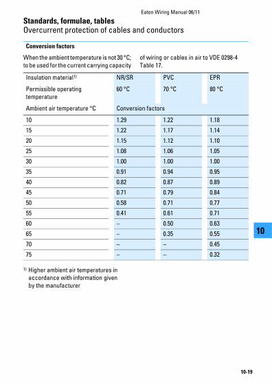
Conversion factors
When the ambient temperature is not 30 °C; to be used for the current carrying capacity
of wiring or cables in air to VDE 0298-4 Table 17.
1) Higher ambient air temperatures inaccordance with information given by the manufacturer
Insulation material1) NR/SR PVC EPR
Permissible operating temperature
60 °C 70 °C 80 °C
Ambient air temperature °C Conversion factors
10 1.29 1.22 1.18
15 1.22 1.17 1.14
20 1.15 1.12 1.10
25 1.08 1.06 1.05
30 1.00 1.00 1.00
35 0.91 0.94 0.95
40 0.82 0.87 0.89
45 0.71 0.79 0.84
50 0.58 0.71 0.77
55 0.41 0.61 0.71
60 – 0.50 0.63
65 – 0.35 0.55
70 – – 0.45
75 – – 0.32
Standards, formulae, tablesOvercurrent protection of cables and conductors
Eaton Wiring Manual 06/11
10-20
1010
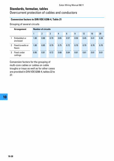
Conversion factors to DIN VDE 0298-4, Table 21
Grouping of several circuits
Conversion factors for the grouping of multi-core cables or cables on cable troughs or trays as well as for other cases are provided in DIN VDE 0298-4, tables 22 to 27.
Arrangement Number of circuits
1 2 3 4 6 9 12 16 20
1 Embedded or enclosed
1.00 0.80 0.70 0.65 0.57 0.50 0.45 0.41 0.38
2 Fixed to walls or floors
1.00 0.85 0.79 0.75 0.72 0.70 0.70 0.70 0.70
3 Fixed under ceilings
0.95 0.81 0.72 0.68 0.64 0.61 0.61 0.61 0.61
Eaton Wiring Manual 06/11
10-21
Standards, formulae, tables
1010
Electrical equipment of machines
Extract from DIN EN 60204-1 (VDE 0113-1)
This standard is used for the electrical equipment of machines, unless there is a product standard (Type C) for the type of machine to be equipped.
Safety requirements regarding the protection of personnel, machines and material according to the European Machinery Safety Directive are highlighted under the heading “Safety of machines”. The degree of possible danger is to be estimated by risk assessment. The standard also includes requirements for equipment, engineering and construction, as well as tests to ensure faultless function and the effectiveness of protective measures. The following paragraphs are an extract from the standard.
Mains isolating device (main switches)
Every machine must be equipped with a manually-operated mains isolating device. It must be possible to isolate the entire electrical equipment of the machine from the mains using the mains isolating device. The breaking capacity must be sufficient to simultaneously disconnect the stalled
current of the largest motor in the machine and the total current drawn by all the other loads in normal operation.
Its Off position must be lockable and must not be indicated until the specified clearances and creepage distances between all contacts have been achieved. It must have only one On and one Off position with associated stops. Star-delta, reversing and multi-speed switches are not permissible for use as mains isolating devices.
The tripped position of circuit-breakers is not regarded as a switch position, therefore there is no restriction on their use as mains isolating devices.
Where there are several incomers, each one must have a mains isolating device. Mutual interlocking must be provided where a hazard may result from only one mains isolating device being switched off. Only circuit-breakers may be used as remotely-operated switches. They must be provided with an additional handle and be lockable in the Off position.
Protection against electric shock
The following measures must be taken to protect personnel against electric shock.
Basic protection/protection against direct
contact
This is understood as meaning protection by means of an enclosure which can only be opened by qualified personnel using a key or special tool. Such personnel is not obliged to disable the mains isolating
device before opening the enclosure. Live parts must be protected against direct contact in accordance with DIN EN 50274 or VDE 0660-514.
Where the mains isolating device is interlocked with the door, the restrictions mentioned in the previous paragraph cease to apply because the door can only be opened when the mains isolating device is switched off. It is permissible for an
Standards, formulae, tablesElectrical equipment of machines
Eaton Wiring Manual 06/11
10-22
1010
interlock to be removable by an electrician using a tool, e.g. in order to search for a fault. Where an interlock has been removed, it must still be possible to switch off the mains isolating device.
Where it is possible for an enclosure to be opened without using a key and without disconnection of the mains isolating device, all live parts must at the very least comply with IP2X or IPXXB degree of
protection in accordance with DIN EN 60529; VDE 0470-1.
Fault protection – Protection against
indirect contact
This involves prevention of a dangerous touch voltage resulting from faulty insulation. To meet this requirement, protective measures in accordance with IEC 60364-4-410; VDE 0100-410 must be used.
Protection of equipment
Protection in the event of power failure
When the power returns following a failure in the supply, machines or parts of machines must not start automatically where this would result in a dangerous situation or damage to property. With contactor controls this requirement can easily be met via self-maintaining circuits.
For circuits with two-wire control, an additional contactor relay with three-wire control in the input wiring to the actuating circuit can carry out this function. Mains isolating devices and motor-protective circuit-breakers with undervoltage releases also reliably prevent automatic restarting on return of voltage.
Overcurrent protection
No overcurrent protective device is normally required for the mains supply cable. Overcurrent protection is provided by the protective device at the head of the input wiring. All other circuits must be protected by means of fuses or circuit-breakers.
The stipulation for fuses is that replacement must be freely obtainable in the country in which the fuses are used.
This difficulty can be avoided by using circuit-breakers, with the added benefits of all-pole disconnection, rapid operational readiness and prevention of single-phasing.
Overload protection of motors
Continuously operating motors above 0.5 kW must be protected against overload. Overload protection is recommended for all other motors. Motors which are frequently starting and braking are difficult to protect and often require a special protective device. Built-in thermal sensors are particularly suitable for motors with restricted cooling. In addition, the fitting of overload relays is always recommended, particularly as protection in the event of a stalled rotor.

Standards, formulae, tablesElectrical equipment of machines
Eaton Wiring Manual 06/11
10-23
1010
Control functions in the event of a fault
A fault in the electrical equipment must not result in a dangerous situation or in damage. Suitable measures must be taken to prevent danger from arising. The expense of using appropriate measures can be extremely high if applied generally. To permit a better assessment of the magnitude of the risk in conjunction with the respective application, the standard DIN EN ISO 13849-1 has been published: “Safety-related parts of control systems Part 1: General rules for design”.
The use of risk assessment to DIN EN ISO 13849-1 is dealt with in the Eaton safety manual “Safety Technology for Machines and Systems” (Order No. PU05907001Z).
Emergency switching off device
Every machine which could potentially cause danger must be equipped with an emergency switching off device which, in a main circuit may be an emergency switching off switch, and in a control circuit an emergency switching off control circuit device.
Actuation of the Emergency-Stop device must result in all current loads which could directly result in danger, being disconnected by de-energization via another device or circuit, i.e. electromechanical devices such as contactors, contactor relays or the undervoltage release of the mains isolating device.
For direct manual operation, emergency switching off control circuit devices must have a mushroom-head push-button and positively opening contacts. Once the emergency switching off control circuit
device has been actuated, it must only be possible to restart the machine after local resetting. Resetting alone must not allow restarting.
Furthermore, the following apply for both emergency-stop switch and emergency switching off control circuit device:
• The handle must be red with a yellow background
• Emergency switching off devices must be quickly and easily accessible in the event of danger
• The emergency switching off function must take precedence over all other functions and operations
• It must be possible to determine functional capability by means of tests, especially in severe environmental conditions.
• Where there is separation into several Emergency-Stop areas, it must be clearly discernible to which area an Emergency-Stop device applies
Emergency operations
It is not clear however from the term emergency switching off which functions are carried out with this. In order to be able to give a more precise definition here, DIN EN 60204-1 describes two specific functions:
1. Devices for emergency stopThis involves the possibility of stopping hazardous motion as quickly as possible.
2. Devices for emergency switching off Where there is a risk of an electric shock by direct contact, e.g. with live parts in electrical operating areas, then an Emergency-Off device shall be provided.
Standards, formulae, tablesElectrical equipment of machines
Eaton Wiring Manual 06/11
10-24
1010
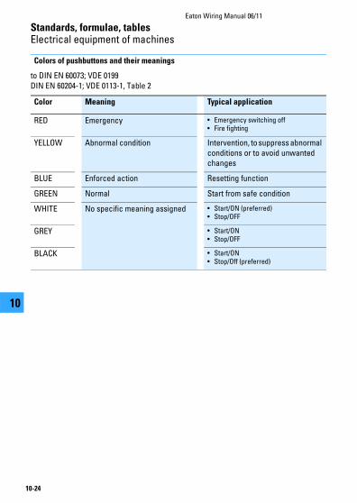
Colors of pushbuttons and their meanings
to DIN EN 60073; VDE 0199 DIN EN 60204-1; VDE 0113-1, Table 2
Color Meaning Typical application
RED Emergency • Emergency switching off• Fire fighting
YELLOW Abnormal condition Intervention, to suppress abnormal conditions or to avoid unwanted changes
BLUE Enforced action Resetting function
GREEN Normal Start from safe condition
WHITE No specific meaning assigned • Start/ON (preferred)• Stop/OFF
GREY • Start/ON• Stop/OFF
BLACK • Start/ON• Stop/Off (preferred)
Standards, formulae, tablesElectrical equipment of machines
Eaton Wiring Manual 06/11
10-25
1010
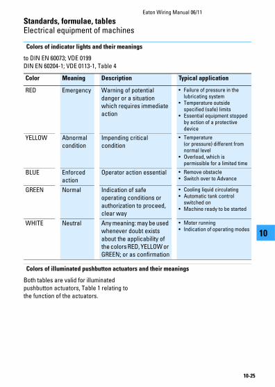
Colors of indicator lights and their meanings
to DIN EN 60073; VDE 0199 DIN EN 60204-1; VDE 0113-1, Table 4
Colors of illuminated pushbutton actuators and their meanings
Both tables are valid for illuminated pushbutton actuators, Table 1 relating to the function of the actuators.
Color Meaning Description Typical application
RED Emergency Warning of potential danger or a situation which requires immediate action
• Failure of pressure in the lubricating system
• Temperature outside specified (safe) limits
• Essential equipment stopped by action of a protective device
YELLOW Abnormal condition
Impending critical condition
• Temperature (or pressure) different from normal level
• Overload, which is permissible for a limited time
BLUE Enforced action
Operator action essential • Remove obstacle• Switch over to Advance
GREEN Normal Indication of safe operating conditions or authorization to proceed, clear way
• Cooling liquid circulating• Automatic tank control
switched on• Machine ready to be started
WHITE Neutral Any meaning: may be used whenever doubt exists about the applicability of the colors RED, YELLOW or GREEN; or as confirmation
• Motor running• Indication of operating modes
Standards, formulae, tablesElectrical equipment of machines
Eaton Wiring Manual 06/11
10-26
1010
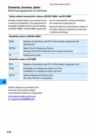
Safety-related characteristic values to EN ISO 13849-1 and IEC 62061
A safety-related system can consist of one or several components. The assessment of the safety-related parts of a control system to EN ISO 13849-1 and IEC 62061 require the
use of characteristic values provided by the component manufacturer.
Eaton provides the characteristic values of all safety-related components in the area of safety technology.
Further details are provided in the overview of the safety-related characteristic values for components:
http://www.moeller.net/binary/bl_supplements/bl8896de.pdf
Reliability values to EN ISO 13849-1
B10d Number of operations until 10 % of the tested components fail dangerously.
MTTFd Mean Time To Dangerous Failure.Average of the time expected up to a dangerous failure
PL Performance Level
Reliability values to IEC 62061
B10 Number of operations until 10 % of the tested components fail.
PFHd Probability of a Dangerous Failure per HourProbability of a dangerous failure per hour
SIL CL Safety Integrity Level Claim Limit. SIL claim limit (for a subsystem).

Eaton Wiring Manual 06/11
10-27
Standards, formulae, tables
1010
Measures for risk reduction
Risk reduction in the fault scenario
A fault in the electrical equipment must not result in a dangerous situation or in
damage. Suitable measures must be taken to prevent danger from arising.
The use of proven circuits and components
a All switching functions on the non-earthed side
b Use of break devices with positively opening contacts (not to be confused with interlocked opposing contacts)
c Shut-down by de-excitation (fail-safe in the event of wire breakage)
d Circuit engineering measures which make undesirable operating states in the fault scenario unlikely (in this instance, simultaneous interruption via contactor and position switch)
e Switching of all live conductors to the device to be controlled
f Chassis earth connection of the actuating circuit for operational purposes (not used as a protective measure)
Redundancy
This means the existence of an additional device or system which takes over the function in the fault scenario.
L01
0
K1
K1I
⎧⎪⎪⎪⎪⎨⎪⎪⎪⎪⎩
⎧⎪⎨⎪⎩
L1
L2
L02
Standards, formulae, tablesMeasures for risk reduction
Eaton Wiring Manual 06/11
10-28
1010
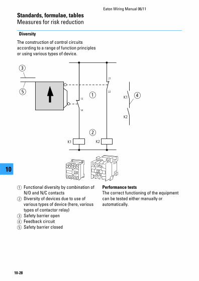
Diversity
The construction of control circuits according to a range of function principles or using various types of device.
a Functional diversity by combination of N/O and N/C contacts
b Diversity of devices due to use of various types of device (here, various types of contactor relay)
c Safety barrier open d Feedback circuite Safety barrier closed
Performance tests
The correct functioning of the equipment can be tested either manually or automatically.
c
ed
K1 K2
K1
K2
13
14
21
22
a
b

Eaton Wiring Manual 06/11
10-29
Standards, formulae, tables
1010
Protection types for electrical equipment
Protection types for electrical equipment by enclosures, covers and similar to
DIN EN 60529; VDE 0470-1
The designation to indicate degrees of enclosure protection consists of the characteristic letters IP (Ingress Protection) followed by two characteristic numerals. The first numeral indicates the
degree of protection of persons against contact with live parts and of equipment against ingress of solid foreign bodies and dust, the second numeral the degree of protection against the ingress of water.
Protection against contact and foreign bodies
First numeral
Degree of protection
Description Explanation
0 Not protected No special protection of persons against accidental contact with live or moving parts. No protection of the equipment against ingress of solid foreign bodies.
1 Protection against solid objects ≧ 50 mm
Protection against contact with live parts with back of hand. The access probe, sphere 50 mm diameter, must have enough distance from dangerous parts. The probe, sphere 50 mm diameter, must not fully penetrate.
2 Protection against solid objects ≧ 12.5 mm
Protection against contact with live parts with a finger.The articulated test finger, 12 mm diameter and 80 mm length, must have sufficient distance from dangerous parts. The probe, sphere 12.5 mm diameter, must not fully penetrate.

Standards, formulae, tablesProtection types for electrical equipment
Eaton Wiring Manual 06/11
10-30
1010
Protection against contact and foreign bodies
First numeral
Degree of protection
Description Explanation
3 Protection against solid objects ≧ 2.5 mm
Protection against contact with live parts with a tool.The entry probe, 2.5 mm diameter, must not penetrate.The probe, 2.5 mm diameter, must not penetrate.
4 Protection against solid objects ≧ 1 mm
Protection against contact with live parts with a conductor.The entry probe, 1.0 mm diameter, must not penetrate.The probe, 1.0 mm diameter, must not penetrate.
5 Protection against accumulation of dust
Protection against contact with live parts with a conductor.The entry probe, 1.0 mm diameter, must not penetrate.The ingress of dust is not totally prevented, but dust does not enter in sufficient quantity to interfere with satisfactory operation of the equipment or with safety.
6 Protection against the ingress of dust
Dust-tight
Protection against contact with live parts with a conductor.The entry probe, 1.0 mm diameter, must not penetrate.No entry of dust.
Example for stating degree of protection: IP 4 4
Characteristic letter
First numeral
Second numeral
Standards, formulae, tablesProtection types for electrical equipment
Eaton Wiring Manual 06/11
10-31
1010
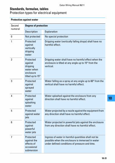
Protection against water
Second numeral
Degree of protection
Description Explanation
0 Not protected No special protection
1 Protected against vertically dripping water
Dripping water (vertically falling drops) shall have no harmful effect.
2 Protected against dripping water when enclosure tilted up to 15°
Dripping water shall have no harmful effect when the enclosure is tilted at any angle up to 15° from the vertical.
3 Protected against sprayed water
Water falling as a spray at any angle up to 60° from the vertical shall have no harmful effect.
4 Protected against splashing water
Water splashed against the enclosure from any direction shall have no harmful effect.
5 Protected against water jets
Water projected by a nozzle against the equipment from any direction shall have no harmful effect.
6 Protected against powerful water jets
Water projected in powerful jets against the enclosure from any direction shall have no harmful effect.
7 Protected against the effects of occasional submersion
Ingress of water in harmful quantities shall not be possible when the enclosure is immersed in water under defined conditions of pressure and time.

Standards, formulae, tablesProtection types for electrical equipment
Eaton Wiring Manual 06/11
10-32
1010
8 Protected against the effects of submersion
Ingress of water in harmful quantities must not be possible when the equipment is continuously submerged in water under conditions which are subject to agreement between manufacturer and user.These conditions must be more stringent than those for characteristic numeral 7.
9K1) Protected during cleaning using high-pressure/steam jets
Water which is directed against the enclosure under extremely high pressure from any direction must not have any harmful effects.Water pressure of 100 barWater temperature of 80 °C
1) This characteristic numeral originates from DIN 40050 9.
Second numeral
Degree of protection
Description Explanation
NotesEaton Wiring Manual 06/11
10-33
1010
Eaton Wiring Manual 06/11
10-34
Standards, formulae, tables
1010
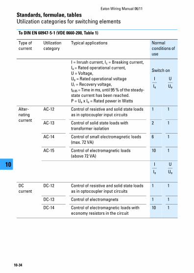
Utilization categories for switching elements
To DIN EN 60947-5-1 (VDE 0660-200, Table 1)
Type of current
Utilization category
Typical applications Normal conditions of use
I = Inrush current, Ic = Breaking current,Ie = Rated operational current, U = Voltage,Ue = Rated operational voltageUr = Recovery voltage,t0.95 = Time in ms, until 95 % of the steady-state current has been reached.P = Ue x Ie = Rated power in Watts
Switch on
Alter-nating current
AC-12 Control of resistive and solid state loads as in optocoupler input circuits
1 1
AC-13 Control of solid state loads with transformer isolation
2 1
AC-14 Control of small electromagnetic loads (max. 72 VA)
6 1
AC-15 Control of electromagnetic loads (above 72 VA)
10 1
DC current
DC-12 Control of resistive and solid state loads as in optocoupler input circuits
1 1
DC-13 Control of electromagnets 1 1
DC-14 Control of electromagnetic loads with economy resistors in the circuit
10 1
I
Ie
U
Ue
I
Ie
U
Ue
Standards, formulae, tablesUtilization categories for switching elements
Eaton Wiring Manual 06/11
10-35
1010
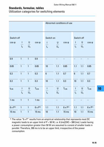
Abnormal conditions of use
Switch off Switch on Switch off
cos ϕ cos ϕ cos ϕ cos ϕ
0.9 1 1 0.9 – – – – – –
0.65 1 1 0.65 10 1.1 0.65 1.1 1.1 0.65
0.3 1 1 0.3 6 1.1 0.7 6 1.1 0.7
0.3 1 1 0.3 10 1.1 0.3 10 1.1 0.3
t0.95 T0.95 T0.95 T0.95
1 ms 1 1 1 ms – – – – – –
6 x P1) 1 1 6 x P1) 1.1 1.1 6 x P1) 1.1 1.1 6 x P1)
15 ms 1 1 15 ms 10 1.1 15 ms 10 1.1 15 ms
1) The value “6 x P” results from an empirical relationship that represents most DC magnetic loads to an upper limit of P = 50 W, i.e. 6 [ms]/[W] = 300 [ms]. Loads having a power consumption greater than 50 W are assumed to consist of smaller loads in parallel. Therefore, 300 ms is to be an upper limit, irrespective of the power consumption.
I
Ie
U
Ue
I
Ie
U
Ue
I
Ie
U
Ue
I
Ie
U
Ue
I
Ie
U
Ue
I
Ie
U
Ue

Eaton Wiring Manual 06/11
10-36
Standards, formulae, tables
1010
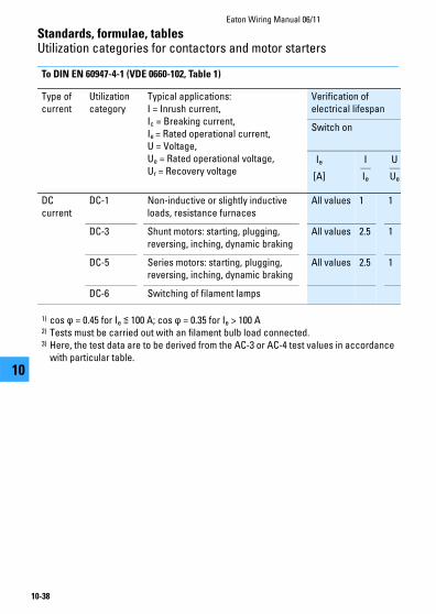
Utilization categories for contactors and motor starters
To DIN EN 60947-4-1 (VDE 0660-102, Table 1)
Type of current
Utilization category
Typical applications:I = Inrush current, Ic = Breaking current,Ie = Rated operational current, U = Voltage,Ue = Rated operational voltageUr = Recovery voltage
Verification of electrical lifespan
Switch on
Alter-nating current
AC-1 Non-inductive or slightly inductive loads, resistance furnaces
All values
1 1
AC-2 Slip-ring motors: starting, switch off All values
2.5 1
AC-3 Normal AC induction motors: starting, switch off during running4)
Ie ≦ 17Ie > 17
66
11
AC-4 Normal AC induction motors: starting, plugging, reversing, inching
Ie ≦ 17Ie > 17
66
11
AC-5a Switching of electric discharge lamp controls
AC-5b Switching of filament lamps
AC-6a3) Switching of transformers
AC-6b3) Switching of capacitor banks
AC-7a Slightly inductive loads in household appliances and similar applications
Data as supplied by the manufacturer
AC-7b Motor load for domestic applications
AC-8a Switching of hermetically enclosed refrigerant compressor motors with manual reset of overload releases5)
AC-8b Switching of hermetically enclosed refrigerant compressor motors with automatic reset of overload releases5)
Ie
[A]
I
Ie
U
Ue
Standards, formulae, tablesUtilization categories for contactors and motor starters
Eaton Wiring Manual 06/11
10-37
1010
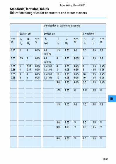
Verification of switching capacity
Switch off Switch on Switch off
cos ϕ
cos ϕ
cos ϕ
cos ϕ
0.95 1 1 0.95 All values
1.5 1.05 0.8 1.5 1.05 0.8
0.65 2.5 1 0.65 All values
4 1.05 0.65 4 1.05 0.8
0.650.35
11
0.170.17
0.650.35
Ie ≦ 100Ie > 100
88
1.051.05
0.450.35
88
1.051.05
0.450.35
0.650.35
66
11
0.650.35
Ie ≦ 100Ie > 100
1010
1.051.05
0.450.35
1010
1.051.05
0.450.35
3.0 1.05 0.45 3.0 1.05 0.45
1.52) 1.05 2) 1.52) 1.05 2)
1.5 1.05 0.8 1.5 1.05 0.8
8.0 1.05 1) 8.0 1.05 1)
6.0 1.05 1) 6.0 1.05 1)
6.0 1.05 1) 6.0 1.05 1)
Ic
Ie
Ur
Ue
Ie
[A]
I
Ie
U
Ue
Ic
Ie
Ur
Ue
Standards, formulae, tablesUtilization categories for contactors and motor starters
Eaton Wiring Manual 06/11
10-38
1010
To DIN EN 60947-4-1 (VDE 0660-102, Table 1)
Type of current
Utilization category
Typical applications:I = Inrush current, Ic = Breaking current,Ie = Rated operational current, U = Voltage,Ue = Rated operational voltage,Ur = Recovery voltage
Verification of electrical lifespan
Switch on
DC current
DC-1 Non-inductive or slightly inductive loads, resistance furnaces
All values 1 1
DC-3 Shunt motors: starting, plugging, reversing, inching, dynamic braking
All values 2.5 1
DC-5 Series motors: starting, plugging, reversing, inching, dynamic braking
All values 2.5 1
DC-6 Switching of filament lamps
1) cos ϕ = 0.45 for Ie ≦ 100 A; cos ϕ = 0.35 for Ie > 100 A2) Tests must be carried out with an filament bulb load connected.3) Here, the test data are to be derived from the AC-3 or AC-4 test values in accordance
with particular table.
Ie
[A]
I
Ie
U
Ue

Standards, formulae, tablesUtilization categories for contactors and motor starters
Eaton Wiring Manual 06/11
10-39
1010
Verification of switching capacity
Switch off Switch on Switch off
L/R [ms]
L/R [ms]
L/R [ms]
L/R [ms]
1 1 1 1 All values
1.5 1.05 1 1.5 1.05 1
2 2.5 1 2 All values
4 1.05 2.5 4 1.05 2.5
7.5 2.5 1 7.5 All values
4 1.05 15 4 1.05 15
1.52) 1.05 2) 1.52) 1.05 2)
4) Devices for utilization category AC-3 may be used for occasional inching or plugging during a limited period such as for setting up a machine; during this limited time period, the number of operations must not exceed a total of five per minute or more than ten in a ten minute period.
5) Hermetically enclosed refrigerant compressor motor means a combination of a compressor and a motor both of which are housed in the same enclosure with no external shaft or shaft seals, the motor running in the coolant.
Ic
Ie
Ur
Ue
Ie
[A]
I
Ie
U
Ue
Ic
Ie
Ur
Ue

Eaton Wiring Manual 06/11
10-40
Standards, formulae, tables
1010
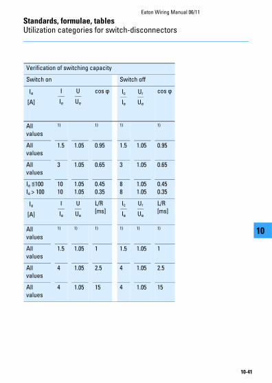
Utilization categories for switch-disconnectors
For switches, switch-disconnectors and fuse-combination units to
DIN EN 60947-3 (VDE 0660-107, Table 2)
Type of current
Utilization category
Typical applications:I = Inrush current,Ic = Breaking current,Ie = Rated operational current,U = Voltage,Ue = Rated operational voltage,Ur = Recovery voltage
Alter-nating current
AC-20 A(B)1) Making and breaking without load
AC-21 A(B)1) Switching resistive loads including low overloads
AC-22 A(B)1) Switching mixed resistive and inductive loads including low overloads
AC-23 A(B)1) Switching motors and other highly inductive loads
DC current
DC-20 A(B)1) Making and breaking without load
DC-21 A(B)1) Switching resistive loads including low overloads
DC-22 A(B)1) Switching mixed resistive and inductive loads, including low overloads (e.g. shunt motors)
DC-23 A(B)1) Switching highly inductive loads (e.g. series motors)
1) A: Frequent actuation, B: Occasional actuation
Switch-disconnectors that are suitable for switching motors are also tested according to the criteria stated in → Section ”Utilization categories for contactors and motor starters”, page 10-36.
Standards, formulae, tablesUtilization categories for switch-disconnectors
Eaton Wiring Manual 06/11
10-41
1010
Verification of switching capacity
Switch on Switch off
cos ϕ cos ϕ
All values
1) 1) 1) 1)
All values
1.5 1.05 0.95 1.5 1.05 0.95
All values
3 1.05 0.65 3 1.05 0.65
Ie ≦100Ie > 100
1010
1.051.05
0.450.35
8 8
1.051.05
0.450.35
L/R[ms]
L/R[ms]
All values
1) 1) 1) 1) 1) 1)
All values
1.5 1.05 1 1.5 1.05 1
All values
4 1.05 2.5 4 1.05 2.5
All values
4 1.05 15 4 1.05 15
Ie
[A]
I
Ie
U
Ue
Ic
Ie
Ur
Ue
Ie
[A]
I
Ie
U
Ue
Ic
Ie
Ur
Ue
NotesEaton Wiring Manual 06/11
10-42
1010

Eaton Wiring Manual 06/11
10-43
Standards, formulae, tables
1010
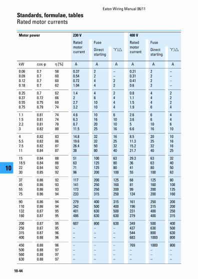
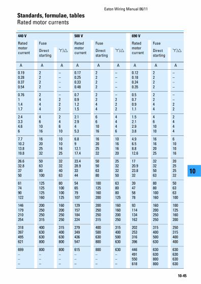
Rated motor currents
Rated motor currents for three-phase motors
(recommended value for squirrel cage motors)
Minimum fuse size for short-circuit
protection of three-phase motors
The maximum value is determined by the switching device or overload relay.
The rated motor currents are for standard 1500 r.p.m. three-phase motors with normal inner and outer surface cooling.
Rated fuse currents for /Δ starting also apply to three-phase motors with slip-ring rotors.
For higher rated currents, starting currents and/or longer starting times, larger fuses will be required.
This table applies to “slow” or “gL” fuses (VDE 0636).
In the case of NH fuses with aM
characteristics, fuses are to be selected
according to their rated operational
current.
D.O.L. starting: Maximum starting current: 6 x rated motor current, maximum starting time: 5 sec.
/Δ starting: Maximum starting current: 2 x rated motor current, maximum starting time: 15 sec.Motor overload relay in phase current: set to 0.58 x rated motor current.
Standards, formulae, tablesRated motor currents
Eaton Wiring Manual 06/11
10-44
1010
Motor power 230 V 400 V
Rated motor current
Fuse Rated motor current
Fuse
Direct starting
/Δ Direct starting
/Δ
kW cos ϕ η [%] A A A A A A
0.060.090.120.18
0.70.70.70.7
58606062
0.370.540.721.04
2244
––22
0.210.310.410.6
2222
––––
0.250.370.550.75
0.70.720.750.79
62666974
1.422.73.2
461010
2444
0.81.11.51.9
4446
2224
1.11.52.23
0.810.810.810.82
74747880
4.66.38.711.5
10162025
6101016
2.63.656.6
661016
44610
45.57.511
0.820.820.820.84
83868787
14.819.626.438
32325080
16253240
8.511.315.221.7
20253240
10161625
1518.52230
0.840.840.840.85
88889292
51637196
100125125200
638080100
29.3364155
636380100
32405063
37455575
0.860.860.860.86
92939394
117141173233
200250250315
125160200250
688199134
125160200200
80100125160
90110132160
0.860.860.870.87
94949595
279342401486
400500630630
315400500630
161196231279
250315400400
200200250315
200250315400
0.870.870.870.88
95959696
607–––
800–––
630–––
349437544683
5006308001000
400500630800
450500560630
0.880.880.880.88
96979797
––––
––––
––––
769–––
1000–––
800–––
Standards, formulae, tablesRated motor currents
Eaton Wiring Manual 06/11
10-45
1010
440 V 500 V 690 V
Rated motor current
Fuse Rated motor current
Fuse Rated motor current
Fuse
Direct starting
/Δ Direct starting
/Δ Direct starting
/Δ
A A A A A A A A A
0.190.280.370.54
2222
––––
0.170.250.330.48
2222
––––
0.120.180.240.35
2222
––––
0.7611.41.7
2444
–222
0.70.91.21.5
2244
–222
0.50.70.91.1
2244
––22
2.43.34.66
461016
24610
2.12.945.3
661016
4446
1.52.12.93.8
461010
2444
7.710.213.819.8
16202532
10101625
6.8912.117.4
16202532
10161620
4.96.58.812.6
16162025
6101016
26.632.83750
506380100
32324063
23.428.93344
50506380
25323250
1720.923.832
32325063
20252532
617490122
125125125160
80100100125
546579107
100125160200
638080125
39475878
8080100160
506363100
146179210254
200250250315
160200250250
129157184224
200250250315
160160200250
93114134162
160200250250
100125160200
318397495621
400630630800
315400630800
279349436547
400500630800
315400500630
202253316396
315400500630
250315400400
699–––
800–––
800–––
615–––
800–––
630–––
446491550618
630630800800
630630630630
Eaton Wiring Manual 06/11
10-46
Standards, formulae, tables
1010
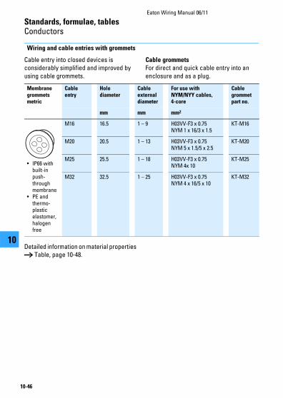
Conductors
Wiring and cable entries with grommets
Cable entry into closed devices is considerably simplified and improved by using cable grommets.
Cable grommets
For direct and quick cable entry into an enclosure and as a plug.
Detailed information on material properties → Table, page 10-48.
Membrane grommets metric
Cable entry
Hole diameter
Cable external diameter
For use with NYM/NYY cables, 4-core
Cable grommetpart no.
mm mm mm2
• IP66 with built-in push-through membrane
• PE and thermo-plastic elastomer, halogen free
M16 16.5 1 – 9 H03VV-F3 x 0.75NYM 1 x 16/3 x 1.5
KT-M16
M20 20.5 1 – 13 H03VV-F3 x 0.75NYM 5 x 1.5/5 x 2.5
KT-M20
M25 25.5 1 – 18 H03VV-F3 x 0.75NYM 4x 10
KT-M25
M32 32.5 1 – 25 H03VV-F3 x 0.75NYM 4 x 16/5 x 10
KT-M32

Standards, formulae, tablesConductors
Eaton Wiring Manual 06/11
10-47
1010
Wiring and cable entries with cable glands
Detailed information on material properties → Table, page 10-48.
Metric cable glands to DIN EN 50262; VDE 0619
with 9, 10, 12, 14 or 15 mm long thread.
Cable glands Cable entry
Hole diameter
Cable external diameter
For use with NYM/NYY cables, 4-core
Cable glandspart no.
mm mm mm2
• With lock nut and built-in strain relief
• IP68 up to 5 bar, polyamide, halogen free
M12 12.5 3 –7 H03VV-F3 x 0.75NYM 1 x 2.5
V-M12
M16 16.5 4.5 – 10 H05VV-F3 x 1.5NYM 1 x 16/3 x 1.5
V-M16
M20 20.5 6 – 13 H05VV-F4 x 2.5/3 x 4NYM 5 x 1.5/5 x 2.5
V-M20
M25 25.5 9 – 17 H05VV-F5 x 2.5/5 x 4NYM 5 x 2.5/5 x 6
V-M25
M32 32.5 13 – 21 NYM 5 x 10 V-M32
M32 32.5 18 – 25 NYM 5 x 16 V-M32G1)
M40 40.5 16 – 28 NYM 5 x 16 V-M40
M50 50.5 21 – 35 NYM 4 x 35/5 x 25 V-M50
M63 63.5 34 – 48 NYM 4 x 35 V-M63
Ventilation cable glands IP69K
M20 20.5 6 – 13 H05VV-F 4 x 2.5/3 x 4NYM 5 x 1.5/5 x 2.5
V-M20-VENT
1) Not in compliance with DIN EN 50262.
Standards, formulae, tablesConductors
Eaton Wiring Manual 06/11
10-48
1010
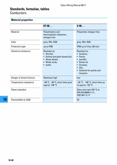
Material properties
KT-M… V-M…
Material Polyethylene and thermoplastic elastomer, halogen free
Polyamide, halogen free
Color grey, RAL 7035 grey, RAL 7035
Protection type up to IP66 IP68 up to 5 bar (30 min)
Chemical resistance Resistant to: • Alcohol, • Animal and plant-based oils, • Weak alkalis, • Weak acids,• water
Resistant to: • Acetone, • Petrol, • paraffin, • Diesel oil, • Greases, • Oils, • Solvents for paints and
lacquers
Danger of stress fracture Relatively high low
Temperature resistance –40 °C…80 °C, short-time up to approx. 100 °C
–20 °C…100 °C, short-time up to approx. 120 °C
Flame retardant – Glow-wire test 750 °C to DIN EN 60695-2-11; VDE 0471-2-11
Flammability to UL94 – V2

Standards, formulae, tablesConductors
Eaton Wiring Manual 06/11
10-49
1010
External diameter of conductors and cables
NYM: light plastic-sheated cable NYY: plastic-sheathed cable H05RR-F: light rubber-sheathed flexible cable (NLH + NSH)
NYCY: cable with concentric conductor and plastic sheathNYCWY: cable with concentric wave-form conductor and plastic sheath
Number of conductors
Approximate external diameter (mean value of various makes)
NYM NYY H05 H07 NYCY
RR-F RN-F NYCWY
Cross section mm mm mm mm mmmm2 max. max. max.2 x 1.5 10 11 9 10 122 x 2.5 11 13 13 11 143 x 1.5 10 12 10 10 133 x 2.5 11 13 11 12 143 x 4 13 17 – 14 153 x 6 15 18 – 16 163 x 10 18 20 – 23 183 x 16 20 22 – 25 224 x 1.5 11 13 9 11 134 x 2.5 12 14 11 13 154 x 4 14 16 – 15 164 x 6 16 17 – 17 184 x 10 18 19 – 23 214 x 16 22 23 – 27 244 x 25 27 27 – 32 304 x 35 30 28 – 36 314 x 50 – 30 – 42 344 x 70 – 34 – 47 384 x 95 – 39 – 53 434 x 120 – 42 – – 464 x 150 – 47 – – 524 x 185 – 55 – – 604 x 240 – 62 – – 705 x 1.5 11 14 12 14 155 x 2.5 13 15 14 17 175 x 4 15 17 – 19 185 x 6 17 19 – 21 205 x 10 20 21 – 26 –5 x 16 25 23 – 30 –8 x 1.5 – 15 – – –10 x 1.5 – 18 – – –16 x 1.5 – 20 – – –24 x 1.5 – 25 – – –
Standards, formulae, tablesConductors
Eaton Wiring Manual 06/11
10-50
1010
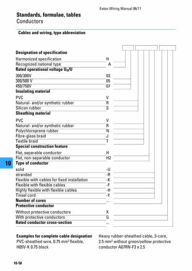
Cables and wiring, type abbreviation
Examples for complete cable designation
PVC-sheathed wire, 0.75 mm2 flexible, H05V-K 0.75 black
Heavy rubber-sheathed cable, 3-core, 2.5 mm2 without green/yellow protective conductor A07RN-F3 x 2.5
Designation of specification
Harmonized specification HRecognized national type ARated operational voltage UO/U
300/300V 03300/500 V 05450/750V 07Insulating material
PVC VNatural- and/or synthetic rubber RSilicon rubber SSheathing material
PVC VNatural- and/or synthetic rubber RPolychloroprene rubber NFibre-glass braid JTextile braid TSpecial construction feature
Flat, separable conductor HFlat, non-separable conductor H2Type of conductor
solid -Ustranded -RFlexible with cables for fixed installation -KFlexible with flexible cables -FHighly flexible with flexible cables -HTinsel cord -YNumber of cores ...Protective conductor
Without protective conductors XWith protective conductors GRated conductor cross-section ...

NotesEaton Wiring Manual 06/11
10-51
1010
Standards, formulae, tablesConductors
Eaton Wiring Manual 06/11
10-52
1010
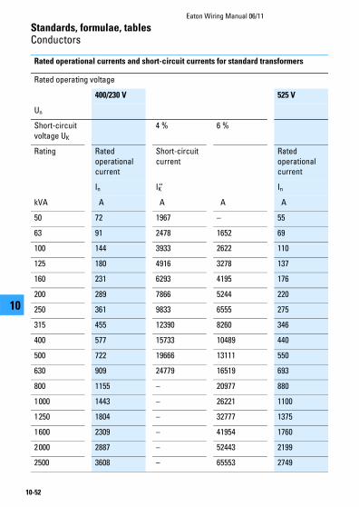
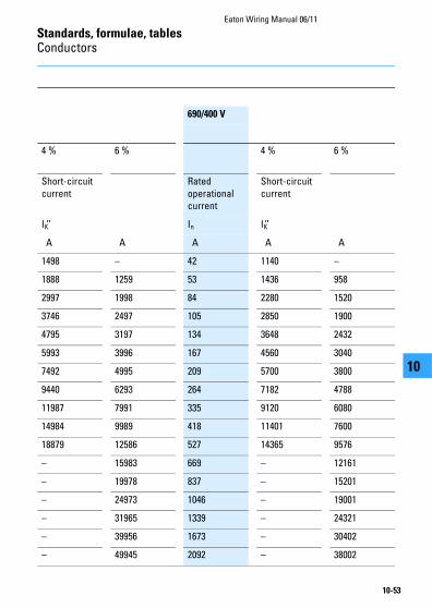
Rated operational currents and short-circuit currents for standard transformers
Rated operating voltage
400/230 V 525 V
Un
Short-circuit voltage UK
4 % 6 %
Rating Rated operational current
Short-circuit current
Rated operational current
In IK’’ In
kVA A A A A
50 72 1967 – 55
63 91 2478 1652 69
100 144 3933 2622 110
125 180 4916 3278 137
160 231 6293 4195 176
200 289 7866 5244 220
250 361 9833 6555 275
315 455 12390 8260 346
400 577 15733 10489 440
500 722 19666 13111 550
630 909 24779 16519 693
800 1155 – 20977 880
1000 1443 – 26221 1100
1250 1804 – 32777 1375
1600 2309 – 41954 1760
2000 2887 – 52443 2199
2500 3608 – 65553 2749
Standards, formulae, tablesConductors
Eaton Wiring Manual 06/11
10-53
1010
690/400 V
4 % 6 % 4 % 6 %
Short-circuit current
Rated operational current
Short-circuit current
IK’’ In IK’’
A A A A A
1498 – 42 1140 –
1888 1259 53 1436 958
2997 1998 84 2280 1520
3746 2497 105 2850 1900
4795 3197 134 3648 2432
5993 3996 167 4560 3040
7492 4995 209 5700 3800
9440 6293 264 7182 4788
11987 7991 335 9120 6080
14984 9989 418 11401 7600
18879 12586 527 14365 9576
– 15983 669 – 12161
– 19978 837 – 15201
– 24973 1046 – 19001
– 31965 1339 – 24321
– 39956 1673 – 30402
– 49945 2092 – 38002
Eaton Wiring Manual 06/11
10-54
Standards, formulae, tables
1010
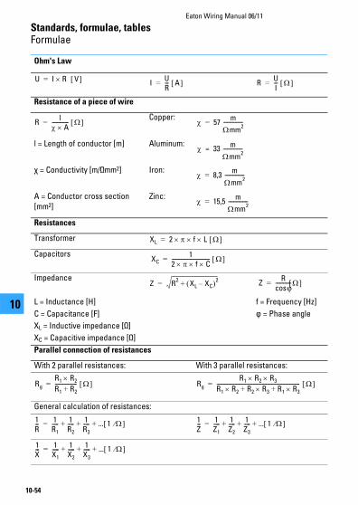
Formulae
Ohm's Law
Resistance of a piece of wire
Copper:
l = Length of conductor [m] Aluminum:
χ = Conductivity [m/Ωmm2] Iron:
A = Conductor cross section [mm2]
Zinc:
Resistances
Transformer
Capacitors
Impedance
L = Inductance [H] f = Frequency [Hz]
C = Capacitance [F] ϕ = Phase angle
XL = Inductive impedance [Ω]
XC = Capacitive impedance [Ω]
Parallel connection of resistances
With 2 parallel resistances: With 3 parallel resistances:
General calculation of resistances:
U I R V = IUR--- A = R
UI--- =
Rl
A------------- = 57
m
mm2
---------------=
33 m
mm2
---------------=
8,3 m
mm2
---------------=
15,5 m
mm2
---------------=
XL 2 f L =
XC1
2 f C----------------------------- =
Z R2
XL XC– 2+= ZR
cosv------------?? =
Rg
R1 R2R1 R2+----------------- = Rg
R1 R2 R3R1 R2 R2 R3 R1 R3++---------------------------------------------------------------- =
1R--- 1
R1
----- 1R2
----- 1R3
----- ... 1 + + += 1Z--- 1
Z1
----- 1Z2
----- 1Z3
----- ... 1 + + +=
1X--- 1
X1
----- 1X2
----- 1X3
----- ... 1 + + +=

Standards, formulae, tablesFormulae
Eaton Wiring Manual 06/11
10-55
1010
Electric power
Mechanical force between 2 parallel conductors
Mechanical force between 3 parallel conductors
Power Current consumption
DC current
Single-phase AC
Alternating current
2 conductors with currents I1 and I2
s = Distance between supports [cm]
a = Distance between conductors [cm]
3 conductors with current I
P U I W =I
PU--- A =
P U I cos W = IP
U cos---------------------- A =
P 3 U I cos W = IP
3 U cos----------------------------------- A =
F20.2 I1 I2 s
a----------------------------------- N = I1
I2
s
a
F3 0.808 F2 N =
F3 0.865 F2 N =
F3 0.865 F2 N =
Standards, formulae, tablesFormulae
Eaton Wiring Manual 06/11
10-56
1010
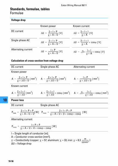
Voltage drop
Calculation of cross-section from voltage drop
Known power Known current
DC current
Single-phase AC
Alternating current
DC current Single-phase AC Alternating current
Known power
Known current
Power loss
DC current Single-phase AC
Alternating current
l = Single length of conductor [m];A = Conductor cross section [mm2];
= Conductivity (copper: = 57; aluminum: = 33; iron: = 8.3 )ΔU = Voltage drop
U 2 l Pz A U----------------------- V = U 2 l l
z A----------------- V =
U 2 l Pz A U----------------------- V = U 2 l l
z A----------------- cos V =
U l Pz A U----------------------- V = U 3
l lz A------------- cos V =
A2 l P
z U U--------------------------- mm
2 = A2 l P
z U U--------------------------- mm
2 = Al P
z U U--------------------------- mm
2 =
A2 l lz U----------------- mm
2 = A2 l lz U----------------- cos mm
2 = A 3l l
z U----------------- cos mm
2 =
Ploss2 l P P
z A U U--------------------------------- W = Ploss
2 l P Pz A U U cosv cosv----------------------------------------------------------------------- W =
Plossl P P
z A U U cosv cosv----------------------------------------------------------------------- W =
z z z zm
Omm2---------------
Standards, formulae, tablesFormulae
Eaton Wiring Manual 06/11
10-57
1010
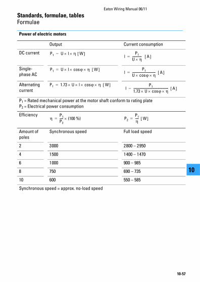
Power of electric motors
Output Current consumption
DC current
Single-phase AC
Alternating current
P1 = Rated mechanical power at the motor shaft conform to rating plateP2 = Electrical power consumption
Efficiency
Amount of poles
Synchronous speed Full load speed
2 3000 2800 – 2950
4 1500 1400 – 1470
6 1000 900 – 985
8 750 690 – 735
10 600 550 – 585
Synchronous speed = approx. no-load speed
P1 U l h W =l
P1
U h------------- A =
P1 U l cosv h W =l
P1
U cosv h-------------------------------- A =
P1 1.73 U l cosv h W =l
P1
1.73 U cosv h------------------------------------------------ A =
hP1
P2
----- (100 %)= P2
P1
h----- W =
Eaton Wiring Manual 06/11
10-58
Standards, formulae, tables
1010
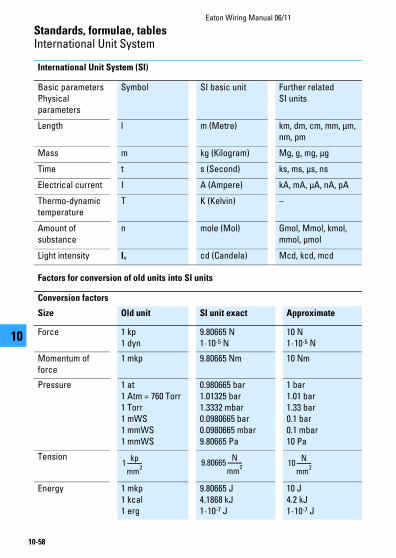
International Unit System
International Unit System (SI)
Factors for conversion of old units into SI units
Basic parameters Physical parameters
Symbol SI basic unit Further related SI units
Length l m (Metre) km, dm, cm, mm, μm, nm, pm
Mass m kg (Kilogram) Mg, g, mg, μg
Time t s (Second) ks, ms, μs, ns
Electrical current I A (Ampere) kA, mA, μA, nA, pA
Thermo-dynamic temperature
T K (Kelvin) –
Amount of substance
n mole (Mol) Gmol, Mmol, kmol, mmol, μmol
Light intensity Iv cd (Candela) Mcd, kcd, mcd
Conversion factors
Size Old unit SI unit exact Approximate
Force 1 kp1 dyn
9.80665 N1·10-5 N
10 N1·10-5 N
Momentum of force
1 mkp 9.80665 Nm 10 Nm
Pressure 1 at1 Atm = 760 Torr1 Torr1 mWS1 mmWS1 mmWS
0.980665 bar1.01325 bar1.3332 mbar0.0980665 bar0.0980665 mbar9.80665 Pa
1 bar1.01 bar1.33 bar0.1 bar0.1 mbar10 Pa
Tension
Energy 1 mkp1 kcal1 erg
9.80665 J4.1868 kJ1·10-7 J
10 J4.2 kJ1·10-7 J
1kp
mm2
---------- 9.80665N
mm2
---------- 10N
mm2
----------
Standards, formulae, tablesInternational Unit System
Eaton Wiring Manual 06/11
10-59
1010
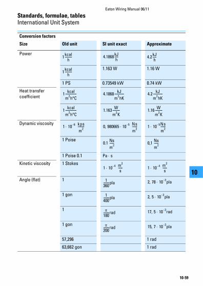
Power
1.163 W 1.16 W
1 PS 0.73549 kW 0.74 kW
Heat transfer coefficient
Dynamic viscosity
1 Poise
1 Poise 0.1
Kinetic viscosity 1 Stokes
Angle (flat) 1
1 gon
1
1 gon
57,296 1 rad
63,662 gon 1 rad
Conversion factors
Size Old unit SI unit exact Approximate
1kcal
h---------- 4.1868
kJh----- 4.2
kJh-----
1kcal
h----------
1kcal
m2h°C
--------------- 4.1868kJ
m2hK
------------- 4.2kJ
m2hK
-------------
1kcal
m2h°C
--------------- 1.163W
m2K
---------- 1.16W
m2K
----------
1 106– kps
m2
--------- 0 980665 105– Ns
m2
------- 1 105– Ns
m2
-------
0.1 Ns
m2
------ 0,1 Ns
m2------
Pa s
1 104– m
2
s------ 1 10
4– m2
s------
1360--------pla 2 78 10
3–pla
1400--------pla 2 5 10
3–pla
180--------rad 17 5 10
3–rad
200--------rad 15 7 10
3–pla
Standards, formulae, tablesInternational Unit System
Eaton Wiring Manual 06/11
10-60
1010
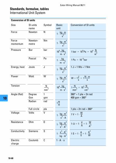
Conversion of SI units
Size SI units name
Symbol Basic unit
Conversion of SI units
Force Newton N
Force momentum
Newton‐metre
Nm
Pressure Bar bar
Pascal Pa
Energy, heat Joule J 1 J = 1 Ws = 1 Nm
Power Watt W
Tension
Angle (flat) DegreeGon
1gon
360° = 1 pla = 2π rad 400 gon = 360°
Radian rad
Full circle pla 1 pla = 2π rad = 360°
Voltage Volts V
Resistance Ohm Ω
Conductivity Siemens S
Electric charge
Coulomb C 1 · A · s
1kg m
s2
--------------
1kg m
2
s2
----------------
105 kg
m s2
------------- 1 bar 105Pa 10
5 N
m2------= =
1kg
m s2
------------- 1 Pa 105–bar=
1kg m
2
s2
----------------
1kg m
2
s3
---------------- W 1=Js--- 1
N ms
------------=
N
mm2
---------- 106 kg
m s2
------------- 1N
mm2
---------- 102 N
cm2
---------=
1mm----
1kg m
2
s3
A---------------- 1 V 1=
WA-----
1kg m
2
s3
A2
---------------- 1 1= VA--- 1
W
A2-----=
1s
3A
2
kg m2
---------------- 1 S 1= AV--- 1=
A2
W-----
Standards, formulae, tablesInternational Unit System
Eaton Wiring Manual 06/11
10-61
1010
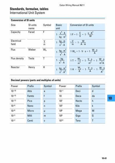
Decimal powers (parts and multiples of units)
Capacity Farad F
Electrical field
Flux Weber Wb
Flux density Tesla T
Reactor Henry H
Power Prefix Symbol Power Prefix Symbol
10–18 Atto a 10–1 Deci d
10–15 Femto f 10 Deca da
10–12 Pico p 102 Hecto h
10–9 Nano n 103 Kilo k
10–6 Micro μ 106 Mega M
10–3 Milli m 109 Giga G
10–2 Centi c 1012 Tera T
Conversion of SI units
Size SI units name
Symbol Basic unit
Conversion of SI units
1s
4A
kg m2
---------------- 1 F 1=CV--- 1
s A2
W------------=
Vm---- 1
kg m
s3
A-------------- 1
Vm---- 1
WA m------------=
1kg m
2
s2
A---------------- 1 Wb 1= V s 1
W sA------------=
1kg
s2
A------------ 1 T
Wb
m2
------- 1V s
m2
---------- 1W s
m2A
------------= = =
1kg m
2
s2
A2
---------------- 1 HWb
A------- 1
V sA---------- 1
W s
A2
------------= = =

Standards, formulae, tablesInternational Unit System
Eaton Wiring Manual 06/11
10-62
1010
Physical units
Mechanical force
Pressure
Obsolete units
SI unit: N (Newton) J/m (Joule/m)
Previous unit: kp (kilopond) dyn (Dyn)
1 N = 1 J/m = 1 kg m/s2 = 0.102 kp = 105 dyn
1 J/m = 1 N = 1 kg m/s2 = 0.102 kp = 105 dyn
1 kg m/s2 = 1 N = 1 J/m = 0.102 kp = 105 dyn
1 kp = 9.81 N = 9.81 J/m = 9.81 kg m/s2 = 0.981 106 dyn
1 dyn = 10–5 N = 10–5 J/m = 10–5 kg m/s2 = 1.02 10–5 kp
SI unit: Pa (Pascal) bar (Bar)
Previous unit: at = kp/cm2 = 10 m WsTorr = mm Hgatm
1 Pa = 1 N/m2 = 10–5 bar
1 Pa = 10–5 bar = 10.2 · 10–6 at = 9.87 · 10–6 at = 7.5 · 10–3 Torr
1 bar = 105 Pa = 1.02 at = 0.987 at = 750 Torr
1 at = 98.1 · 103 Pa = 0.981 bar = 0.968 at = 736 Torr
1 atm = 101.3 · 103 Pa = 1.013 bar = 1.033 at = 760 Torr
1 Torr = 133.3 Pa = 1.333 · 10–3 bar = 1.359 · 10–3 at = 1.316 · 10–3 atm

Standards, formulae, tablesInternational Unit System
Eaton Wiring Manual 06/11
10-63
1010
Work
Power
SI unit: J (Joule) Nm (Newtonmeter)
SI unit:(as before)
Ws (Wattsecond) kWh (Kilowatthour)
Previous unit: kcal (Kilocalorie) = cal · 10–3
1 Ws = 1 J = 1 Nm 107 erg
1 Ws = 278 · 10–9 kWh = 1 Nm = 1 J = 0.102 kpm = 0.239 cal
1 kWh = 3.6 · 106 Ws = 3.6 · 106 Nm = 3.6 · 106 J = 367 · 106 kpm = 860 kcal
1 Nm = 1 Ws = 278 · 10–9 kWh = 1 J = 0.102 kpm = 0.239 cal
1 J = 1 Ws = 278 · 10–9 kWh = 1 Nm = 0.102 kpm = 0.239 cal
1 kpm = 9.81 Ws = 272 · 10–6 kWh = 9.81 Nm = 9.81 J = 2.34 cal
1 kcal = 4.19 · 103 Ws = 1.16 · 10–3 kWh = 4.19 · 103 Nm = 4.19 · 103 J = 427 kpm
SI unit: Nm/s (Newtonmeter/s)J/s (Joule/s)
SI unit:(as before)
W (Watt)kW (Kilowatt)
Previous unit: kcal/s (Kilocalorie/sec.) = cal/s · 103
kcal/h (Kilocalorie/hour.) = cal/h · 106
kpm/s (Kilopondmeter/Sec.)
PS (metric horsepower)
1 W = 1 J/s = 1 Nm/s
1 W = 10–3 kW = 0.102 kpm/s = 1.36 ·10–3 PS = 860 cal/h = 0.239 cal/s
1 kW = 103 W = 102 kpm/s = 1.36 PS = 860 ·103 cal/h = 239 cal/s
1 kpm/s = 9.81 W = 9.81 · 10–3 kW = 13.3 ·10–3 PS = 8.43 ·103 cal/h = 2.34 cal/s
1 PS = 736 W = 0.736 kW = 75 kpm/s = 632 · 103 cal/h = 176 cal/s
1 kcal/h = 1.16 W = 1.16 · 10–3 kW = 119 · 10–3 kpm/s = 1.58 ·10–3 PS = 277.8 · 10–3 cal/s
1 cal/s = 4.19 W = 4.19 · 10–3 kW = 0.427 kpm/s = 5.69 · 10–3 PS = 3.6 kcal/h
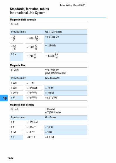
Standards, formulae, tablesInternational Unit System
Eaton Wiring Manual 06/11
10-64
1010
Magnetic field strength
Magnetic flux
Magnetic flux density
SI unit:
Previous unit: Oe = (Oerstedt)
= 0.01256 Oe
= 12.56 Oe
1 Oe
1Am---- 0.001
kAm------=
1kAm------ 1000=
Am----
79.6 Am----= 0.0796
kAm------=
SI unit: Wb (Weber)μWb (Microweber)
Previous unit: M = Maxwell
1 Wb = 1 Tm2
1 Wb = 106 μWb = 108 M
1 μWb = 10–6 Wb = 100 M
1 M = 10–8 Wb = 0.01 μWb
SI unit: T (Tesla)mT (Millitesla)
Previous unit: G = Gauss
1 T = 1 Wb/m2
1 T = 103 mT = 104 G
1 mT = 10–3 T = 10 G
1 G = 0.1–3 T = 0.1 mT
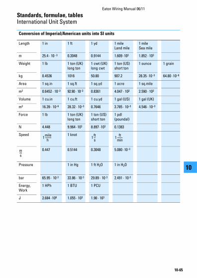
Standards, formulae, tablesInternational Unit System
Eaton Wiring Manual 06/11
10-65
1010
Conversion of Imperial/American units into SI units
Length 1 in 1 ft 1 yd 1 mileLand mile
1 mileSea mile
m 25.4 · 10 –3 0.3048 0.9144 1.609 ·103 1.852 · 103
Weight 1 lb 1 ton (UK)long ton
1 cwt (UK) long cwt
1 ton (US)short ton
1 ounce 1 grain
kg 0.4536 1016 50.80 907.2 28.35 ·10–3 64.80 ·10–6
Area 1 sq.in 1 sq.ft 1 sq.yd 1 acre 1 sq.mile
m2 0.6452 · 10–3 92.90 · 10–3 0.8361 4.047 · 103 2.590 · 103
Volume 1 cu.in 1 cu.ft 1 cu.yd 1 gal (US) 1 gal (UK)
m3 16.39 · 10–6 28.32 · 10–3 0.7646 3.785 · 10–3 4.546 · 10–3
Force 1 lb 1 ton (UK)long ton
1 ton (US)short ton
1 pdl(poundal)
N 4.448 9.964 ·103 8.897 ·103 0.1383
Speed 1 knot
0.447 0.5144 0.3048 5.080 ·10–3
Pressure 1 in Hg 1 ft H2O 1 in H2O
bar 65.95 · 10-3 33.86 · 10-3 29.89 · 10-3 2.491 · 10-3
Energy, Work
1 HPh 1 BTU 1 PCU
J 2.684 ·106 1.055 · 103 1.90 · 103
1mile
h ---------- 1
fts--- 1
ftmin--------
ms----
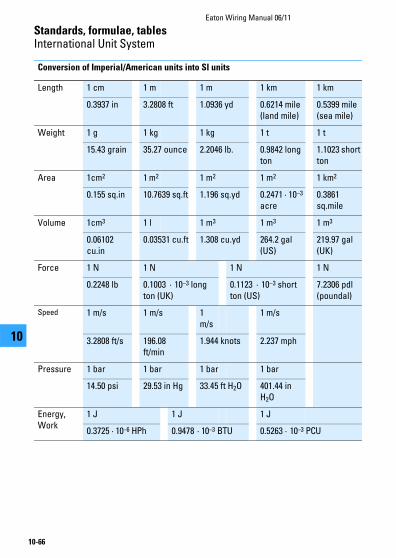
Standards, formulae, tablesInternational Unit System
Eaton Wiring Manual 06/11
10-66
1010
Conversion of Imperial/American units into SI units
Length 1 cm 1 m 1 m 1 km 1 km
0.3937 in 3.2808 ft 1.0936 yd 0.6214 mile (land mile)
0.5399 mile (sea mile)
Weight 1 g 1 kg 1 kg 1 t 1 t
15.43 grain 35.27 ounce 2.2046 lb. 0.9842 long ton
1.1023 short ton
Area 1cm2 1 m2 1 m2 1 m2 1 km2
0.155 sq.in 10.7639 sq.ft 1.196 sq.yd 0.2471 · 10–3 acre
0.3861 sq.mile
Volume 1cm3 1 l 1 m3 1 m3 1 m3
0.06102 cu.in
0.03531 cu.ft 1.308 cu.yd 264.2 gal (US)
219.97 gal (UK)
Force 1 N 1 N 1 N 1 N
0.2248 lb 0.1003 · 10–3 long ton (UK)
0.1123 · 10–3 short ton (US)
7.2306 pdl (poundal)
Speed 1 m/s 1 m/s 1 m/s
1 m/s
3.2808 ft/s 196.08 ft/min
1.944 knots 2.237 mph
Pressure 1 bar 1 bar 1 bar 1 bar
14.50 psi 29.53 in Hg 33.45 ft H2O 401.44 in H2O
Energy, Work
1 J 1 J 1 J
0.3725 · 10–6 HPh 0.9478 · 10–3 BTU 0.5263 · 10–3 PCU