star 104 - high resolution atmospheric sensing using uavs
TRANSCRIPT

High Resolution Atmospheric Sensing UsingUAVs
Bobby Hodgkinson, Doug Lipinski, Liqian Peng, and Kamran Mohseni�
Abstract. A technique to obtain high resolution atmospheric data using small mo-bile sensors is presented. A fluid based control scheme using smoothed particlehydrodynamics (SPH) is implemented to perform field measurements in a leader-follower arrangement for a team of unmanned aerial vehicles (UAVs) equipped withenvironmental sensors. A virtual leader is created by using a reduced density SPHparticle to guide the unmanned aerial vehicles along a desired path. Simulationsusing the control scheme demonstrate excellent measurement ability, swarm coher-ence, and leader following capability for large swarms. A K-means algorithm is usedto reduce the measurement error and provide accurate interpolation of the field mea-surement data. Experimental results are presented which demonstrate the guidanceand collision avoidance properties of the control scheme using real UAVs. Readingsfrom the UAV’s temperature and humidity sensor suite are used with the K-meansalgorithm to produce a smooth estimation of the respective distribution fields.
1 Introduction
Several methods of sensing the atmosphere exist and can be classified into two pri-mary groups: remote sensing or in situ. Well-known systems in the remote sensinggroup include RADAR, LIDAR, weather satellites, etc. [3, 5, 13, 29]. These sys-tems are typically large (on the order of cubic meters), are generally focused on
Bobby Hodgkinson · Doug Lipinski · Liqian PengDepartment of Mechanical and Aerospace Engineering, Institute for Networked AutonomousSystems, University of Florida, Gainesville, FLe-mail: {hodgkinson,dmlipinski,liqianpeng}@ufl.eduKamran MohseniDepartment of Mechanical and Aerospace Engineering, Department of Electrical andComputer Engineering, Institute for Networked Autonomous Systems, University of Florida,Gainesville, FLe-mail: [email protected]� Corresponding author.
M.A. Hsieh and G. Chirikjian (eds.), Distributed Autonomous Robotic Systems, 31Springer Tracts in Advanced Robotics 104,DOI: 10.1007/978-3-642-55146-8_3, c© Springer-Verlag Berlin Heidelberg 2014
32 B. Hodgkinson et al.
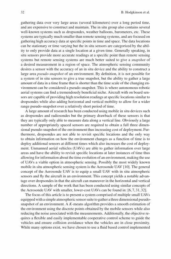
gathering data over very large areas (several kilometers) over a long period time,and are expensive to construct and maintain. The in situ group also contains severalwell-known systems such as dropsondes, weather balloons, barometers, etc. Thesesystems are typically much smaller than remote sensing systems, and are focused ongathering high accuracy data at specific points in time and space. The data locationscan be stationary or time varying but the in situ sensors are categorized by the abil-ity to only provide data at a single location at a given time. Generally speaking, insitu sensors provide more accurate readings at a specific point than remote sensingsystems but remote sensing systems are much better suited to give a snapshot ofa desired measurement in a region of space. The atmospheric sensing communitydesires a sensor with the accuracy of an in situ device and the ability to construct alarge area pseudo-snapshot of an environment. By definition, it is not possible fora system of in situ sensors to give a true snapshot, but the ability to gather a largeamount of data in a time frame that is shorter than the time scale of the changing en-vironment can be considered a pseudo-snapshot. This is where autonomous roboticaerial systems can find a tremendously beneficial niche. Aircraft with on board sen-sors are capable of providing high resolution readings at specific locations similar todropsondes while also adding horizontal and vertical mobility to allow for a widerrange pseudo-snapshot over a relatively short period of time.
A large amount of research has been conducted using mobile in situ devices suchas dropsondes and radiosondes but the primary drawback of these sensors is thatthey are typically only able to measure data along a vertical line. Obviously a largenumber of appropriately spaced sensors are required to obtain a full three dimen-sional pseudo-snapshot of the environment thus increasing cost of deployment. Fur-thermore, dropsondes are not able to revisit specific locations and the only wayto obtain information on how the environment changes as a function of time is todeploy additional sensors at different times which also increases the cost of deploy-ment. Unmanned aerial vehicles (UAVs) are able to gather information over largeareas and have the ability to revisit specific locations at later instances of time thusallowing for information about the time evolution of an environment, making the useof UAVs a viable option in atmospheric sensing. Possibly the most widely knownmobile in situ atmospheric sensing system is the Aerosonde UAV [10]. The generalconcept of the Aerosonde UAV is to equip a small UAV with in situ atmosphericsensors and fly the aircraft in an environment. This concept yields a notable advan-tage over dropsondes in that the aircraft can maneuver in the horizontal and verticaldirections. A sample of the work that has been conducted using similar concepts ofthe Aerosonde UAV with smaller, lower-cost UAVs can be found in: [6, 7, 31, 32].
The focus of this article is to present a system comprised of multiple small UAVsequipped with a simple atmospheric sensor suite to gather a three dimensional pseudo-snapshot of an environment. A K-means algorithm provides a smooth estimation ofthe environment using the discrete points obtained by the mobile sensors while alsoreducing the noise associated with the measurements. Additionally, the objective re-quires a flexible and easily implementable cooperative control scheme to guide thevehicles and ensure collision avoidance when the vehicles are in close proximity.While many options exist, we have chosen to use a fluid based control implemented

High Resolution Atmospheric Sensing Using UAVs 33
with the Smoothed Particle Hydrodynamics (SPH) fluid dynamics scheme due toseveral desirable characteristics. This scheme treats each vehicle as an individualfluid particle and the control forces are determined by the SPH approximation of theNavier-Stokes equations of fluid motion. This technique ensures collision avoidanceand also creates a flexible controller that is computationally reasonable for implemen-tation on resource constrained platforms. While UAVs are used in this demonstration,the SPH control scheme can be applied to ground and underwater robots as well asheterogeneous swarms of robots containing any combination of ground, aerial, andunderwater platforms [11].
In the following sections we present an overview of the SPH control scheme,discuss the error reduction technique, and present test results using multiple UAVsdemonstrating several highly desirable properties of the SPH control scheme. Wealso present error reduced results obtained from data gathered by two UAVs flownusing the SPH control.
2 SPH Control Scheme
While there are many possible control schemes for use with small UAVs, fluid basedcontrol is especially appealing since fluid flows have many properties that a groupof vehicles may wish to mimic [11, 15, 17, 18, 26]. Chiefly, fluids exhibit smoothmotions and do not penetrate obstacles. In terms of vehicle control, these propertiescorrespond to efficient motion and collision/obstacle avoidance. Additionally, UAVsoperate in a fluid environment meaning a fluid based control scheme may allow foreasier integration of strong background flows into the vehicle path planning process.
In particular, the smoothed particle hydrodynamics (SPH) discretization hasproven to be an effective method of applying the Navier-Stokes equations in a con-trol setting [11]. This Lagrangian technique treats each vehicle as a fluid particle,giving fluid-like motion for vehicle swarms with inherent collision and obstacleavoidance. A more complete discussion of the method is available in a review arti-cle by Monaghan [23] or the book by Liu and Liu [19]. Here we present only theaspects of SPH that are used in our cooperative control scheme.
The SPH algorithm is computationally efficient since each vehicle is representedby a single fluid particle. By choosing a compactly supported smoothing kernel forthe particles, it is also possible to limit vehicle interactions to a short range. Thisresults in vehicles interacting with only their nearest neighbors (typically no morethan six vehicles in 2D). The localized interactions also make long range commu-nication unnecessary. These advantages result in a control algorithm that is simpleenough to run in real time using the limited processing capabilities of the robot [30].Additionally, this is a distributed control scheme that requires no central controllersince only local vehicle interactions are used. All the benefits of a distributed controlor peer-to-peer control scheme are thereby included as well [12, 25].
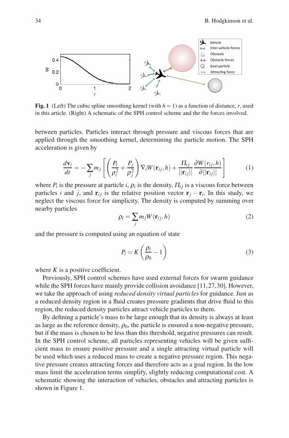
The SPH scheme is dependent on choosing a Gaussian-like smoothing kernelwhich is used to apply fluid properties. We use the cubic spline kernel shown inFigure 1. This kernel is nonzero for ||r|| < 2h and defines the interaction range
34 B. Hodgkinson et al.
Fig. 1 (Left) The cubic spline smoothing kernel (with h= 1) as a function of distance, r, usedin this article. (Right) A schematic of the SPH control scheme and the the forces involved.
between particles. Particles interact through pressure and viscous forces that areapplied through the smoothing kernel, determining the particle motion. The SPHacceleration is given by
dvi
dt=−∑
jm j
[(Pi
ρ2i
+Pj
ρ2j
)∇iW (ri j,h)+
Πi j
||ri j||∂W (ri j,h)
∂ ||ri j||
](1)
where Pi is the pressure at particle i, ρi is the density, Πi j is a viscous force betweenparticles i and j, and ri j is the relative position vector r j − ri. In this study, weneglect the viscous force for simplicity. The density is computed by summing overnearby particles
ρi = ∑j
m jW (ri j,h) (2)
and the pressure is computed using an equation of state
Pi = K
(ρi
ρ0− 1
)(3)
where K is a positive coefficient.Previously, SPH control schemes have used external forces for swarm guidance
while the SPH forces have mainly provide collision avoidance [11,27,30]. However,we take the approach of using reduced density virtual particles for guidance. Just asa reduced density region in a fluid creates pressure gradients that drive fluid to thisregion, the reduced density particles attract vehicle particles to them.
By defining a particle’s mass to be large enough that its density is always at leastas large as the reference density, ρ0, the particle is ensured a non-negative pressure,but if the mass is chosen to be less than this threshold, negative pressures can result.In the SPH control scheme, all particles representing vehicles will be given suffi-cient mass to ensure positive pressure and a single attracting virtual particle willbe used which uses a reduced mass to create a negative pressure region. This nega-tive pressure creates attracting forces and therefore acts as a goal region. In the lowmass limit the acceleration terms simplify, slightly reducing computational cost. Aschematic showing the interaction of vehicles, obstacles and attracting particles isshown in Figure 1.

High Resolution Atmospheric Sensing Using UAVs 35
In the control scheme, the SPH accelerations for a particle due to all nearby(within 2h) particles are computed and passed to the vehicle controller, which at-tempts to enforce the desired motion through a combination of roll, pitch, and thrustcommands.
3 UAV Data Sampling and K-means Approximation
Suppose we want to measure the temperature or humidity of a 3-dimensional region.Our UAVs can quickly collect large amounts of data through the custom temperatureand humidity sensor suite. However, in experimental flights these sensors may notbe highly accurate due to the limitations of sensor response time which is relatedto the rate of change of temperature and humidity over time and space and vehicleflight speed. For this reason, we use a K-means based error reduction scheme to ef-fectively reduce the noise. K-means algorithms can effectively cluster N data pointsinto K clusters. To this effect, the field function has only K unknown coefficientscorresponding to K basis functions. On the other hand, Kriging and Gaussian inter-polation are spanned by N basis functions. Therefore, the K-means algorithm canbe considered as a dimension reduction technique that approximates the field func-tion without significant loss of information. Additionally, the computational cost issignificantly lower for K-means than Kriging and Gaussian process regression ifK � N. One drawback of the K-means algorithm is that it may filter the high fre-quency components of the original field. However, as long as the ensemble of thedata set is large enough and the field is smooth, the K-means algorithm is able tocapture the main modes of the field. This method also enables us to approximatedata at unsampled locations, and potentially (in future work) suggest a path for theUAVs to follow and collect additional data to minimize the existing uncertainty.This section will discuss the effects of noise on the data and introduce the statisticalmethod for noise mitigation and interpolation.
Let x be any point in the measurement domain and xi denote a spatial locationof a sensor measurement at time step i. Each sensor inevitably introduces somelocation error, ξi, and some measurement error, εi. We devise a scheme based on theK-means algorithm to extract information from limited measurements and reducemeasurement noise.
Suppose the original field f (x) is a smooth function of position, sampling pointsxi near x can be used to approximate the field of x,
f (x) = yi + εi + J(x) ·ξi+ J(x) · (x− xi)+O(|x− xi|2)+O(|x− xi| · |ξi|)+O(|ξi|2)
where J(x) is the Jacobian matrix at point x. A better estimator f (x) can be obtainedthrough a linear combination of some measurement results yi. Our goal is to find anoptimal weighting function, ϕn(x,xi) so that the error in f is minimized.
If many points are measured and the measurement error is potentially large thevariance becomes the dominant error. To reduce the noise error, we will use a clusterof points instead of a single point to estimate the unknown field. We use the wellknow K-means algorithm [21] to cluster the data points into K groups. Each cluster
36 B. Hodgkinson et al.
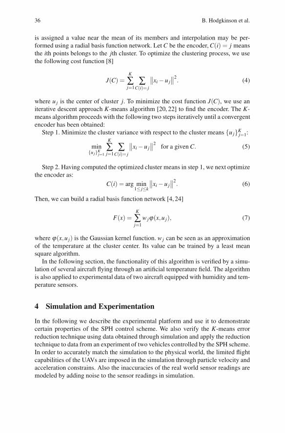
is assigned a value near the mean of its members and interpolation may be per-formed using a radial basis function network. Let C be the encoder, C(i) = j meansthe ith points belongs to the jth cluster. To optimize the clustering process, we usethe following cost function [8]
J(C) =K
∑j=1
∑C(i)= j
∥∥xi − u j∥∥2. (4)
where u j is the center of cluster j. To minimize the cost function J(C), we use aniterative descent approach K-means algorithm [20, 22] to find the encoder. The K-means algorithm proceeds with the following two steps iteratively until a convergentencoder has been obtained:
Step 1. Minimize the cluster variance with respect to the cluster means {u j}Kj=1:
min{u j}K
j=1
K
∑j=1
∑C(i)= j
∥∥xi − u j∥∥2 for a given C. (5)
Step 2. Having computed the optimized cluster means in step 1, we next optimizethe encoder as:
C(i) = arg min1≤ j≤k
∥∥xi − u j∥∥2. (6)
Then, we can build a radial basis function network [4, 24]
F(x) =K
∑j=1
wjϕ(x,u j), (7)
where ϕ(x,u j) is the Gaussian kernel function. wj can be seen as an approximationof the temperature at the cluster center. Its value can be trained by a least meansquare algorithm.
In the following section, the functionality of this algorithm is verified by a simu-lation of several aircraft flying through an artificial temperature field. The algorithmis also applied to experimental data of two aircraft equipped with humidity and tem-perature sensors.
4 Simulation and Experimentation
In the following we describe the experimental platform and use it to demonstratecertain properties of the SPH control scheme. We also verify the K-means errorreduction technique using data obtained through simulation and apply the reductiontechnique to data from an experiment of two vehicles controlled by the SPH scheme.In order to accurately match the simulation to the physical world, the limited flightcapabilities of the UAVs are imposed in the simulation through particle velocity andacceleration constrains. Also the inaccuracies of the real world sensor readings aremodeled by adding noise to the sensor readings in simulation.

High Resolution Atmospheric Sensing Using UAVs 37
4.1 UAV Hardware and Sensor Suite
A UAV equipped with a simple sensor suite and limited onboard computation capa-bilities is used for this study (shown in Figure 2). The aircraft has a wingspan of 0.8m and weighs less than 0.5 kg. The airframe is a single piece of Styrofoam and canbe purchased under the name F-27 Styker; additionally the ailerons, flaps, nose cone,propellers, etc. are all mass produced thus making the aircraft inexpensive comparedto a custom design. This aircraft has been successfully used in several experiments inour research group and has proven itself robust to experimental mishaps, relativelysimple and inexpensive to maintain. Additionally, the small size and simplicity ofthe aircraft allow for rapid deployment by a single pilot in areas that are not ideal fortraditional UAVs. Most importantly, the Delta-Wing UAV is equipped with a customautopilot to allow for implementation of custom control strategies. The CUPIC is acomplete autopilot system developed at the University of Colorado at Boulder [28],and used in a large number of experiments in our (and other) research group(s).Several studies [2, 14] have shown that it is possible to achieve fully autonomousoperation of a small UAV by means of this simple autopilot equipped with a limitednumber of sensors. The work of Floreano et. al [9, 16] has demonstrated the useof a similar fixed wing aircraft in swarm applications by using a different autopilotsystem. Additionally, Sensefly [1] is a Swiss company that provides a UAV that canbe used to gather high resolution imaging using a similar hardware platform.
Fig. 2 Resource constrained delta-wing UAVs used in experiments. The 0.8 m wingspanUAV is equipped with a GPS sensor, a roll rate sensor, a communication radio, and autopilotto control the craft during autonomous operation.
Shaw and Mohseni [30] showed that the CUPIC autopilot is also capable ofdemonstrating fully autonomous, distributed cooperative control of a team of UAVs.The CUPIC, in its most basic design, consists of an on-board processor, a singleaxis rate gyro to sense roll rates, an absolute pressure sensor for altitude sensing,and a GPS receiver for positioning. The autopilot controls the vertical location ofthe aircraft through pitch and thrust commands. The pitch and thrust commandsare determined from the error between the desired altitude and the current altitudeas well as the magnitude of the SPH acceleration from Equation 1. The horizontal

38 B. Hodgkinson et al.
location of the aircraft is controlled by varying the roll angle. The desired roll an-gle is determined by the error between the direction of the SPH acceleration vector(from Equation 1) and the aircraft’s current heading vector. Virtual saturation lim-its are employed in order to avoid commands which would result in aircraft stallor an excessive roll angle. The program has built-in routines to account for shortterm blackouts in the GPS signals and the noise and drifts in the sensors. The au-topilot has been proven to be fully capable of stable autonomous flight on a widevariety of MAVs including Delta-wing aircrafts [2], warping-wing aircrafts, andgust-insensitive aircrafts [14].
The CUPIC autopilot system also includes a complementary ground stationwhich is comprised of a laptop running a MATLAB routine. The autopilot transmitstelemetry data to the ground station and the ground station transmits commands andthe location of the artificial attracting particle for the SPH control algorithm. TheMATLAB routine includes a user interface that provides pilots and observers realtime information of the aircraft’s GPS position, physical state, sensor suite raw data,and autopilot commands. The graphical interface also includes the ability to alter theartificial particle’s location, speed, and path. A detailed communication characteri-zation of the communication scheme used in the autopilot systems is given in [30].
The autopilot was designed with the ability to interface up to 7 additional analogsensors through on board analog to digital converters. For this experiment a cus-tom board was manufactured to house a HIH-5031 humidity sensor and a LM35temperature sensor. The HIH-5031 humidity sensor and LM35 temperature sensorwere chosen primarily due to size, simplicity and sensing range. The sensors rawoutput voltage is read by the autopilot at 10Hz and transmitted to the ground stationalong with the aircraft’s most recent GPS position. The raw output voltage is thenconverted to percent relative humidity and temperature using equations found in thesensors respective datasheets.
4.2 Verification of SPH Control Scheme
In applications involving autonomous agents the two most important control as-pects are agent guidance and collision avoidance. In this article, agent guidance isaccomplished using a reduced density virtual particle which acts to attract agents toa specific region of space. Collision avoidance is accomplished by setting the SPHparameters of the agents such that they are repelled from each when they reach acertain distance. If the vehicle separation is greater than this distance the agents areonly attracted to the reduced density particle.
The guidance property is demonstrated by placing a stationary attractor particleat a location in the domain and engaging the autopilot with the UAV at some otherpoint in the domain. Figure 3 shows the GPS position of the UAV demonstrating theguidance property. The marker color indicates the magnitude of the SPH force ascalculated by the algorithm. The plane approaches the attracting particle (indicatedby a red ×), passes almost directly over the virtual particle and then begins to doubleback as the direction of the SPH force vector points opposite to the plane’s heading.

High Resolution Atmospheric Sensing Using UAVs 39
Fig. 3 Experimental demonstration of SPH control properties using small, resource con-strained UAVs. (Left) Experimental results of a single vehicle (colored ◦) approaching anattractor particle (red ×) from the south and then beginning a loiter pattern around the attrac-tor particle. Color of the ◦ represents the magnitude of SPH force calculated by the vehicle.Results taken from a small portion of large flight experiment. (Right) Experimental results ofa single vehicle (colored ◦) avoiding another aircraft (black �) while loitering an attractingparticle (red ×). The blue dashed line indicates the previous loiter circle achieved by plane1 prior to interaction with plane 2. Color of the ◦ represents the magnitude of SPH forcecalculated by the vehicle.
The plane then enters into a loiter circle which is a result of a balance between theSPH force magnitude and physical limitations (i.e. turning radius) of the aircraft.For this and all following experiments, aircraft were given an h value of 30 and theattractor particle was given an h value of 200; the average of the two h values wereused to determine the SPH force per Equation 1.
The collision avoidance property is demonstrated with two flying aircraft. Figure3 plots the information received from a single vehicle (plane 1): ◦ represent the vehi-cle’s GPS position colored by the calculated SPH force magnitude, the red × repre-sents the location of the attractor particle, � represent the GPS position of the othervehicle (plane 2) as known by plane 1. The dashed line represents the loiter circleachieved by plane 1 prior to interaction with plane 2. Plane 1 loitered in a clock-wise direction while plane 2 loitered in a counter clockwise direction. As the twoplanes approach each other, both planes make corrections to their respective coursesavoiding potential collision as evident in the course correction of plane 1. The SPHforce magnitude range is greater for collision avoidance than attraction due to thefact that the interaction between planes results in a higher repulsive force than theattraction force experienced between a plane and the attracting particle. Simulationshave been previously conducted showing the smooth collision avoidance propertyof the SPH control technique [27] and these experimental results correspond well tothe simulations. Although collision avoidance may not be guaranteed in real-worldsituations where packet loss and location error play a role, incorporating a safetyfactor into the inter-vehicle spacing provides high confidence that collisions will beavoided.

40 B. Hodgkinson et al.
Fig. 4 Two ways to achieve loiter circles using SPH control scheme and UAVs. (Left) GPScoordinates of a single vehicle (blue •) in a series of loiter circles around a stationary attractorparticle (red ×). The loiter circles are a result of a balance between the SPH force and thephysical limitations of the aircraft. (Right) Experimental results of a single vehicle (blue •)following a moving attracting particle (red ×) demonstrating a different method of achievinga loiter.
Due to the fact that fixed wing aircraft must maintain a forward velocity to stayaloft, a loiter circle is a common technique employed in experiments involving fixedwing aircraft. One way of achieving a loiter circle using SPH control is with a sta-tionary attractor particle and imposed acceleration and velocity constraints on themoving particle. The moving particle will move directly towards the attracting par-ticle until it passes the particle. Due to specified constraints, the moving particlewill then bank one way and eventually find and maintain an equilibrium balancingthe SPH force and the imposed constraints resulting in a loiter. This property wasexperimentally verified and the results can be seen in Figure 4 which shows the GPSlocation for a single aircraft (blue •) loitering around a stationary attractor (red ×).
While a stationary particle allows for a loiter circle, the radius of the circle is afunction of several parameters and thus the radius of the loiter is not easy to predict.It is difficult to maintain a uniform loiter since any disturbance to the vehicle’s pathcould result in the plane taking a more direct approach over the attractor particle asevident in Figure 3. A more robust way to achieve a loiter circle is with a movingattractor particle. If the velocity and acceleration of the attracting particle are withinthe physical limitations of the aircraft, the vehicle will follow closely behind theattractor. This technique is shown in Figure 4 with the GPS location of the aircraftshown as blue • and the attractor location as a red ×. A moving particle allows fora loiter circle of varying radius as well as more complex paths.
4.3 Sensing Using Multiple Vehicles
Next we simulate a more complicated situation involving multiple vehicles takingmeasurements over a large domain to determine the temperature field. The results

High Resolution Atmospheric Sensing Using UAVs 41
are shown in Figure 5. In this simulation, a group of 10 vehicles begins in the lowerleft corner of the domain and travels back and forth across the domain, finishingin the upper right. Each vehicle records a temperature every 0.2 seconds and sendsdata back to the base station. The temperature is generated by the function
T (x,y) =75+ 3[sin(x/50)+ cos(y/42)cos(x/100) (8)
+ 3tan−1((x+ 20)/10)+ cos(√
x2 + y2/40)].
To create a closer approximation of reality and consider the limited accuracy ofonboard temperature sensors, white Gaussian noise with a standard deviation of0.78 is added to the temperature data. Every 5th point of the temperature data isplotted in Figure 5 as a colored circle. The vehicle paths are shown as black curvesand the end vehicle positions are shown as black dots. The SPH controller maintainsan even vehicle spacing throughout the trajectories. By using this well spaced groupof multiple vehicles flying at 15 m/s, a large amount of data is collected over this250,000 sq. m domain in only 160 seconds.
This procedure produces a large amount of data (8000 data points in 160 s) thatcan be used to reduce the noise in the resulting interpolations. By using the afore-mentioned K-means algorithm we are able to interpolate the data over the interior ofthe domain and reduce the error. The K-means clusters for this example are shownin Figure 5. The error in the final temperature approximation can be computed as
E∞ = ||T −Testimate||∞ or ERMS =
√∑n
i (T (xi)−Testimate(xi))2
n
where n is the number of spatial grids, T is the true temperature (given by Equation8) and Testimate is the temperature estimated by the K-means algorithm. We find thatE∞ = 2.32 and ERMS = 0.23 after applying K-means and interpolating. This is animprovement over the raw noisy data that had E∞ = 2.97 and ERMS = 0.79. Thelargest errors occur at the edge of the domain where interpolations are less likely tobe valid due to the limited data in these regions.
In the real world experiments, we measured humidity and temperature using theaforementioned sensor suite placed on the two aircraft used in demonstrating theSPH control scheme. An AcuRite digital humidity and temperature monitor wasused to determine the temperature and percent relative humidity at the ground stationlocation as 36 ◦C and 57% respectively. All the data was collected by two UAVsflying in a series of overlapping loiter circles centered at the location of a stationaryattractor particle as seen in Figure 6. The path of UAV 1 is shown as a dashed blackline, the path of UAV 2 is shown as a red dash-dot line, and the attractor particle isshown as a blue ◦. The loiter circles are a result of a balance between the minimumvelocity enforced by the autopilot to keep the plane aloft and the attraction to theartificial particle. After each plane completed at least 3 loiter circles the location ofthe attractor particle was moved approximately 70 meters to the northeast resultingin the behavior shown in Figure 6. The motion of the aircraft in the horizontal planewas determined by the SPH control law while the vertical location of the aircraft

42 B. Hodgkinson et al.
−200 −100 0 100 200
−200
−100
0
100
200
x [meter]
y[m
eter
]
◦C
26.7
27.8
28.9
30.0
31.1
32.2
33.3
34.4
35.6
−300 −200 −100 0 100 200 300−300
−200
−100
0
100
200
300
x [meter]
y[m
eter
]
Fig. 5 Simulation of data gathering using UAVs equipped with a temperature sensor. (Left)Simulation of 10 vehicles (black ◦’s) that were guided through a 500 × 500 domain by asingle attracting particle. The black curves show the full vehicle paths and the colored ◦’sdenote individual temperature measurements (in ◦C). (Right) The K-means clusters for the10 vehicle simulation. Cluster points are shown in blue, data points are shown in black andthe data-cluster connections are shown in red.
Fig. 6 Flight data of two UAVs demonstrating the SPH control scheme to gather the humiditydistribution of an environment. (Left) UAV 1 path in black dashed line, and UAV 2 path inred dash-dot line. An attractor particle (blue ◦) was placed at (0,0) and then moved to thenortheast to approximately (50,50). (Right) Humidity field results from two aircraft. Theaircraft were flown approximately 40 meters apart (in altitude). The field results show higherrelative humidity at a lower altitude and also a region of higher humidity at approximatelyx = 50 m, y = 0 m.
was maintained by an altitude controller. Regardless of the altitude difference, theaircraft maintain a safe horizontal separation thus avoiding collision if the UAVsaltitude’s were the same. The aircraft were flown at an altitude separation of 40 min order to obtain three dimensional data about the temperature and humidity fields.
The noise of the sensor readings was rather high (approximately 10%), in orderto approximate the entire field and minimize error we implemented the K-meansmethod to reduce the noise. The results from the K-means approximations for thetwo aircraft are then used to find humidity and temperature as a smooth function of

High Resolution Atmospheric Sensing Using UAVs 43
space. Figure 6 shows the resulting humidity fields obtained from the two aircraft attheir respective average altitude.
The test environment was a dry retention pond surrounded by woods. The re-sults show a higher relative humidity centered at approximately (x = 50 m, y = 0 m)which is at the edge of the wooded region. While more tests are required to makeconclusive remarks, the higher relative humidity over a region of trees is likely in-dicative of increased evaporation over this region compared to the dry retentionpond.
5 Conclusions
An SPH based controller has been successfully implemented that includes a re-duced density virtual attracting particle for vehicle guidance of autonomous UAVswith limited processing capabilities. The temperature and humidity data collectioncapabilities of multiple UAVs were demonstrated. Additionally, these UAVs experi-mentally verified several desirable properties of the SPH control scheme. Althoughthe examples presented here are two-dimensional, all the techniques used are validin three dimensions, but have been artificially restricted to constant altitude for sim-plicity and an added level of safety.
Additional simulations have been implemented to demonstrate the multi-vehiclecapabilities of the SPH controller as pertinent to the data collection opportuni-ties made possible by swarms of sensor equipped UAVs that can quickly collectdata over a large two or three dimensional region. This is in contrast to the com-monly used data collection methods available today (i.e. remote sensing, dropson-des, weather balloons, etc.). Furthermore, uncertainties in the sensor readings aremitigated using a K-means algorithm that is well suited to process and interpolatethe data over a desired region to minimize errors. The data processing algorithmwas implemented on a set of humidity and temperature data gathered by a pair ofaircraft equipped with sensors flying in several loiter patterns as governed by theSPH control.
References
1. Sensefly autonomous ultralight uav for professionals@ONLINE (October 2012)2. Allred, J., Hasan, A., Pisano, B., Panichsakul, S., Gray, P., Han, R., Lawrence, D.,
Mohseni, K.: SensorFlock: A mobile system of networked micro-air vehicles. In: TheACM SenSys 2007: The 5th ACM Conference on Embedded Networked Sensor Sys-tems, Sydney, Australia, November 6-9 (2007)
3. Amzajerdian, F., Pierrottet, D., Petway, L., Hines, G., Roback, V.: Lidar systems forprecision navigation and safe landing on planetary bodies, p. 7 (2011)
4. Buhmann, M.D.: Radial Basis Functions: Theory and Implementations. Cambridge Uni-versity (2003)
5. Campbell, J.: Introduction to Remote Sensing. The Guilford Press (1996)

44 B. Hodgkinson et al.
6. Corrigan, C.E., Roberts, G.C., Ramana, M.V., Kim, D., Ramanathan, V.: Capturing ver-tical profiles of aerosols and black carbon over the Indian Ocean using autonomous un-manned aerial vehicles. Atmospheric Chemistry & Physics Discussions 7, 11429–11463(2007)
7. Hardin, P., Jensen, R.: Small-scale unmanned aerial vehicles in environmental remotesensing: Challenges and opportunities (2011)
8. Hastie, T., Tibshirani, R., Friedman, J.: The Elements of Statistical Learning: Data Min-ing, Inference, and Prediction. Springer (2009)
9. Hauert, S., Leven, S., Varga, M., Ruini, F., Cangelosi, A., Zufferey, J., Floreano, D.:Reynolds flocking in reality with fixed-wing robots: communication range vs. maximumturning rate. In: 2011 IEEE/RSJ International Conference on Intelligent Robots and Sys-tems (IROS), pp. 5015–5020. IEEE (2011)
10. Holland, G., Webster, P., Curry, J., Tyrell, G., Gauntlett, D., Brett, G., Becker, J., Hoag,R., Vaglienti, W.: The aerosonde robotic aircraft: A new paradigm for environmentalobservations. Bulletin of the American Meteorological Society 82(5) (May 2001)
11. Huhn, S., Mohseni, K.: Cooperative control of a team of AUVs using smoothed particlehydrodynamics with restricted communication. In: Proceedings of the ASME 28th In-ternational Conference on Ocean, Offshore and Arctic Engineering, Honalulu, HA, May31-June 5, OMAE 2009-79869 (2009)
12. Jadbabaie, A., Lin, J., Morse, A.S.: Coordination of groups of mobile autonomous agentsusing nearest neighbor rules. IEEE Transactions on Automatic Control 48(6) (2003)
13. Jensen, J.R.: Remote Sensing of the Environment: An Earth Resource Perspective, 2ndedn. Prentice Hall (May 2006)
14. Lawrence, D., Frew, E., Pisano, W.: Lyapunov vector fields for autonomous unmannedaircraft flight control. Journal of Guidance, Control, and Dynamics 31(5), 1220–1229(2008)
15. Pimenta, R.M.L.C.A., Mendes, M.L., Pereira, G.: Fluids in electrostatic fields: An anal-ogy for multirobot control. IEEE Transactions on Magnetics 43(4) (2007)
16. Leven, S., Zufferey, J.-C., Floreano, D.: Dealing with Mid-Air Collisions in Dense Col-lective Aerial Systems. Journal of Field Robotics 28(3), 405–423 (2011)
17. Lipinski, D., Mohseni, K.: Cooperative control of a team of unmanned vehicles usingsmoothed particle hydrodynamics. AIAA paper 2010-8316, AIAA Guidance, Naviga-tion, and Control Conference, Toronto, Ontario, Canada, August 2-5 (2010)
18. Lipinski, D., Mohseni, K.: A master-slave fluid cooperative control algorithm for optimaltrajectory planning. In: 2011 IEEE International Conference on Robotics and Automa-tion (ICRA), pp. 3347–3351. IEEE (2011)
19. Liu, G., Liu, M.: Smoothed particle hydrodynamics: a meshfree particle method. WorldScientific (2003)
20. Lloyd, S.P.: Least square quantization in pcm. IEEE Transactions on Information The-ory 28(2), 129–137 (1982)
21. MacKay, D.: Information Theory, Inference and Learning Algorithms. Cambridge Uni-versity Press, New York (2003)
22. MacQueen, J.B.: Some methods for classification and analysis of multivariate observa-tions. In: Proceedings of 5th Berkeley Symposium on Mathematical Statistics and Prob-ability, pp. 281–297 (1967)
23. Monaghan, J.: Smoothed particle hydrodynamics. Annual Review of Astronomy andAstrophysics 30, 543–574 (1992)
24. Moody, J., Darken, C.J.: Fast learning in networks of locally tuned processing units.Neural Computation 1, 281–294 (1989)

High Resolution Atmospheric Sensing Using UAVs 45
25. Olfati-Saber, R.: Flocking for multi-agent dynamic systems: Algorithms and theory.IEEE Transactions on Automatic Control 51(3), 401–420 (2006)
26. Pimenta, L., Michael, N., Mesquita, R., Pereira, G., Kumar, V.: Control of swarms basedon hydrodynamic models. In: IEEE International Conference on Robotics and Automa-tion (May 2008)
27. Pimenta, L., Michael, N., Mesquita, R., Pereira, G., Kumar, V.: Control of swarms basedon hydrodynamic models. In: IEEE International Conference on Robotics and Automa-tion, pp. 1948–1953 (May 2008)
28. Pisano, W.J., Lawrence, D.A.: Autonomous UAV control using a 3-sensor autopilot.AIAA paper 2007-2756, American Institute of Aeronautics and Astronautics, InfotechAerospace Conference, Rohnert Park, CA (May 2007)
29. Richards, M., Scheer, J., Holm, W.: Principles of Modern Radar Basic Principles.SciTECH Publishing Inc. (2010)
30. Shaw, A., Mohseni, K.: A fluid dynamic based coordination of a wireless sensor networkof unmanned aerial vehicles: 3-d simulation and wireless communication characteriza-tion. IEEE Sensors Journal 11(3), 722–736 (2011)
31. Spiess, T., Bange, J., Buschmann, M., Vorsmann, P.: First application of the meteorolog-ical Mini UAV M2AV. Meteorologische Zeitschrift 16(2), 159–169 (2007)
32. van den Kroonenberg, A., Martin, S., Beyrich, F., Bange, J.: Spatially-Averaged Tem-perature Structure Parameter Over a Heterogeneous Surface Measured by an UnmannedAerial Vehicle. Boundary-Layer Meteorology 142, 55–77 (2011)