star: synthesis of stateful logic in rram targeting high
TRANSCRIPT

1
STAR: Synthesis of Stateful Logic in RRAMTargeting High ARea Utilization
Feng Wang1,∗, Guojie Luo1,#, Guangyu Sun1, Jiaxi Zhang1, Jinfeng Kang2,Yuhao Wang3, Dimin Niu3, Hongzhong Zheng3
1Center for Energy-efficient Computing and Applications, Peking University, Beijing, China2Institute of Microelectronics, Peking University, Beijing, China
3Pingtouge, Alibaba GroupEmail: {∗yzwangfeng, #gluo}@pku.edu.cn
Abstract—Processing-in-memory (PIM) exploits massive par-allelism with high energy efficiency and becomes a promisingsolution to the von Neumann bottleneck. Recently, the emergingmetal-oxide Resistive Random Access Memory (RRAM) showsits potential to construct a PIM architecture, because severalstateful logic operations, e.g., IMP and NOR, can be executed inan RRAM crossbar in parallel. Previous synthesis flows focuson improving latency with stateful logic operations, but theyignore that the memory should be used primarily for storage.i.e., most of the area in the crossbar is used for computationbut not storage. In this situation, storage and computation stillhave to be separated into different crossbars, which leads toconsiderable data transfer overhead and limited parallelism.
In this work, we define the ratio of storage in a crossbar asarea utilization. We aim to improve the area utilization withoutthroughput loss by proposing STAR, a novel synthesis flow for thestateful logic. We present two optimization strategies to reducethe computation area in STAR. First, we reduce the area forredundant inputs. For the shared constants among differentrows (or columns), we encode them as immediate values intothe control signals without writing them into the crossbar atrun time. For the other inputs, we only store one copy of themin the crossbar. Second, we reduce the area for intermediatevariables by reusing invalid cells. And we design a schedulingalgorithm to find a computation sequence with the minimalvariable erasing cycles. Invalid primary inputs can also be erasedin this algorithm. Furthermore, we present a case study of theimage convolution to demonstrate the effectiveness of STAR.Experimental evaluation shows that STAR achieves 33.03% morearea utilization and a 1.43x throughput compared to SIMPLER,the state-of-the-art stateful logic synthesis flow. Our imageconvolution implementation also provides 78.36% more areautilization and a 1.48x throughput compared with IMAGING, thestate-of-the-art stateful logic based image processing accelerator.
Index Terms—synthesis, memory, scheduling, performance op-timization
I. INTRODUCTION
Huge energy-hungry data transfer between processors andmemory has been the limitation of computation speed andenergy efficiency, i.e., the von Neumann bottleneck [1]. To al-leviate the memory wall, researchers have explored to processdata within the memory, which is an attractive solution.
This work is partly supported by Beijing Municipal Science and TechnologyProgram under Grant No. Z201100004220007, Key Area R&D Program ofGuangdong Province with grant No. 2018B030338001, Beijing Academyof Artificial Intelligence (BAAI), and Alibaba Innovative Research (AIR)Program.
The metal-oxide Resistive Random Access Memory(RRAM) is one type of non-volatile memories (NVM) [2].It has emerged as one of the most promising technologies toimplement a processing-in-memory (PIM) architecture for tworeasons. First, it is a non-volatile, ultra-compact memory withlow leakage power and excellent scalability. Industrial demon-strations have been presented [3] to showcase the viability oflarge memory crossbars (GB level in total with 512×512 bitsper crossbar). Second, digital RRAM has been demonstratedto perform stateful logic operations [4] beyond storage. Itis possible to combine computation and storage in the sameRRAM crossbar due to its flexibility.
In a digital RRAM crossbar, each RRAM cell can storeone-bit information because it has two different resistancestates, the low resistance state (LRS) and the high resistancestate (HRS). These two states can be switched by applyingcertain voltage patterns. For RRAM cells that are connectedin series, they can change the states of others under specificvoltage patterns. This important feature has been leveragedfor computation, and several stateful logic operations havebeen conducted in recent years, including IMP [4], NOR [5],NAND [6], and OR [7].
Besides the PIM benefit, RRAM also provides massive Sin-gle Instruction Multiple Lines (SIML)-fashion parallelism [8].In an RRAM crossbar, we can implement multiple statefullogic operations along different columns (or rows) in parallelby applying the same voltage pattern [9], if the input and theoutput RRAM cells are aligned along rows (or columns). Thedegree of parallelism can reach the size of the crossbar andscale with the data size due to the PIM capability of RRAM.On contrary, the degree of parallelism in the conventional vonNeumann architecture is limited by the amount of computingresources, e.g., Arithmetic Logical Units (ALUs). Despite theirequivalence in computation capability, we can achieve lowertime complexity in RRAM if fully exploiting its parallelism.
To utilize the PIM feature and the SIML-fashion parallelismof RRAM, storage and computation have to be combined in thesame RRAM crossbars. Otherwise, data need to be transferredfrom storage crossbars to computation crossbars at run time,which still introduces a considerable overhead [20]. Also,the parallelism is dominated by the number of computationcrossbars and cannot scale with the data size. Furthermore, tomeet this requirement and still suit for storage, storage haveto take up the major part in the crossbar.

2
64 bits
24 bits
64 bits
512 bits
512 bits
170bits
Input image
Negative copy #1
Filter copy
#1 Outputimage
…
Image copy #2
Negative copy #2
...
…
Image copy #3
Negative copy #3
...
Filter copy #170
original image
input copies / common constants
intermediate variables
Fig. 1: Data layout during the computation procedure of imageconvolution in IMAGING. For a 3×3 filter and a 512×512RRAM crossbar, the maximum input image size is 170×8with 8 bits per pixel.
TABLE I: Ultra-low area utilization of previous works. Welist the result of the state-of-the-art work SIMPLER for eachbenchmark.
Benchmark Work Area utilization
ISCAS’85 [10]
Logic [9] 3.69%Scalable [11] 2.52%
Look-ahead [12] 2.64%Staircase [13] 2.01%
SAID [14] 8.25%SIMPLER [15] 63.21%
LgSynth’91 [16] SIMPLE [17] 8.02%SIMPLER 48.49%
IWLS’93 [18] SIMPLER 41.93%Image convolution IMAGING [19] 8.10%
In this work, we define:
area utilizationdef====
storage area
crossbar area, (1)
which represents the ratio of storage in the crossbar. Specifi-cally, for a logic function implemented in the RRAM crossbar,the storage consists of inputs and outputs, and its area utiliza-tion becomes
area utilization =|inputs|+ |outputs|bounding box area
. (2)
The synthesis flow for the stateful logic should have higharea utilization and reduce the area for redundant inputs,intermediate variables, unused cells as much as possible.
For example, Fig. 1 shows the data layout during the com-putation procedure of image convolution in IMAGING [19].Despite of high parallelism, the area utilization of imageconvolution is 8.30%. Several copies of the input image andthe filter occupy 25.53% of the crossbar, and the intermediatevariables occupy 66.17%. To combine storage and compu-tation in the same crossbar, 25.53%+66.17%=91.70% of the
metal
metal
insulator
WL
BL
(a) Structure.
HRS (logical 0)
LRS(logical 1)
SET (𝑈"# − 𝑈%# > 𝑉()* )
RESET (𝑈%# − 𝑈"# > 𝑉+)()* )
(b) State transitions.
Fig. 2: Schematic of an RRAM cell.
crossbar needs to be reserved for computation. Assuming thatwe have a 1 GB RRAM, we can only store 83 MB images init. It cannot play the role of storage well.
As shown in Table I, most of the previous synthesisflows [9], [17], [11], [12], [13], [14] optimize the latencyof a given logic function at a cost of less than 10% areautilization. Large amount of extra inputs and intermediatevariables are written into the crossbar during computation,and more than half of the RRAM cells are unused. SIM-PLER [15] optimizes the throughput instead of the latencyby reusing invalid cells and computing multiple instances inparallel. However, its reusing algorithm cannot get the optimalcomputation sequence. As a result, the area utilization stillstays around 50%.
For a given crossbar size and a synthesis flow, consideringthat the throughput (per crossbar) is proportional to the area forcomputation, it is unacceptable to improve the area utilizationdirectly in previous works, which will lead to a significantthroughput loss. To address this problem, we propose STAR,a novel synthesis flow for the stateful logic in RRAM, inthis work. The key point is to improve the area utilizationwithout throughput loss. The main contributions of this workare listed as follows:
• We propose STAR, a synthesis flow for stateful logic inRRAM, which improves area utilization by reducing thearea for primary inputs and intermediate variables withoutthroughput loss.
• We present a case study of the image convolution. We firstdesign a dense data placement scheme and then performhighly parallel computation using the limited area underthe guide of STAR.
• We experimentally evaluate STAR and the image con-volution implementation with the state-of-the-art workson the stateful logic to show our advantages in areautilization and throughput.
The rest of this paper is organized as follows. Section IIsummarizes the mechanism of the stateful logic. Section IIIproposes the synthesis flow in detail. In Section IV, we presenta case study of the image convolution. The proposed synthesisflow STAR and the image convolution implementation areevaluated with experimental results in Section V. Finally,Section VI introduces some related works, and Section VIIconcludes the paper.
3
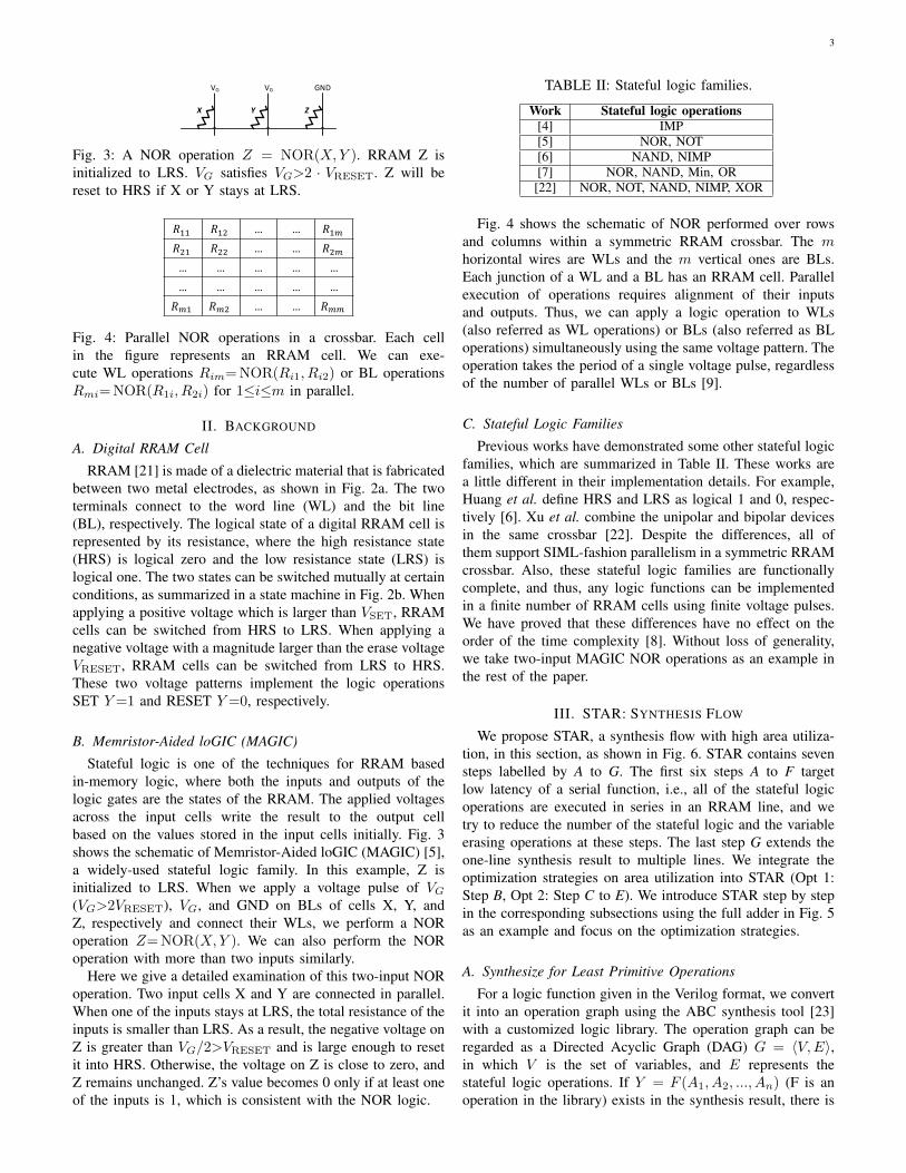
VG VG GND
Fig. 3: A NOR operation Z = NOR(X,Y ). RRAM Z isinitialized to LRS. VG satisfies VG>2 · VRESET. Z will bereset to HRS if X or Y stays at LRS.
𝑅"" 𝑅"# … … 𝑅"$𝑅#" 𝑅## … … 𝑅#$… … … … …
… … … … …
𝑅$" 𝑅$# … … 𝑅$$
Fig. 4: Parallel NOR operations in a crossbar. Each cellin the figure represents an RRAM cell. We can exe-cute WL operations Rim=NOR(Ri1, Ri2) or BL operationsRmi=NOR(R1i, R2i) for 1≤i≤m in parallel.
II. BACKGROUND
A. Digital RRAM Cell
RRAM [21] is made of a dielectric material that is fabricatedbetween two metal electrodes, as shown in Fig. 2a. The twoterminals connect to the word line (WL) and the bit line(BL), respectively. The logical state of a digital RRAM cell isrepresented by its resistance, where the high resistance state(HRS) is logical zero and the low resistance state (LRS) islogical one. The two states can be switched mutually at certainconditions, as summarized in a state machine in Fig. 2b. Whenapplying a positive voltage which is larger than VSET, RRAMcells can be switched from HRS to LRS. When applying anegative voltage with a magnitude larger than the erase voltageVRESET, RRAM cells can be switched from LRS to HRS.These two voltage patterns implement the logic operationsSET Y=1 and RESET Y=0, respectively.
B. Memristor-Aided loGIC (MAGIC)
Stateful logic is one of the techniques for RRAM basedin-memory logic, where both the inputs and outputs of thelogic gates are the states of the RRAM. The applied voltagesacross the input cells write the result to the output cellbased on the values stored in the input cells initially. Fig. 3shows the schematic of Memristor-Aided loGIC (MAGIC) [5],a widely-used stateful logic family. In this example, Z isinitialized to LRS. When we apply a voltage pulse of VG(VG>2VRESET), VG, and GND on BLs of cells X, Y, andZ, respectively and connect their WLs, we perform a NORoperation Z=NOR(X,Y ). We can also perform the NORoperation with more than two inputs similarly.
Here we give a detailed examination of this two-input NORoperation. Two input cells X and Y are connected in parallel.When one of the inputs stays at LRS, the total resistance of theinputs is smaller than LRS. As a result, the negative voltage onZ is greater than VG/2>VRESET and is large enough to resetit into HRS. Otherwise, the voltage on Z is close to zero, andZ remains unchanged. Z’s value becomes 0 only if at least oneof the inputs is 1, which is consistent with the NOR logic.
TABLE II: Stateful logic families.
Work Stateful logic operations[4] IMP[5] NOR, NOT[6] NAND, NIMP[7] NOR, NAND, Min, OR[22] NOR, NOT, NAND, NIMP, XOR
Fig. 4 shows the schematic of NOR performed over rowsand columns within a symmetric RRAM crossbar. The mhorizontal wires are WLs and the m vertical ones are BLs.Each junction of a WL and a BL has an RRAM cell. Parallelexecution of operations requires alignment of their inputsand outputs. Thus, we can apply a logic operation to WLs(also referred as WL operations) or BLs (also referred as BLoperations) simultaneously using the same voltage pattern. Theoperation takes the period of a single voltage pulse, regardlessof the number of parallel WLs or BLs [9].
C. Stateful Logic Families
Previous works have demonstrated some other stateful logicfamilies, which are summarized in Table II. These works area little different in their implementation details. For example,Huang et al. define HRS and LRS as logical 1 and 0, respec-tively [6]. Xu et al. combine the unipolar and bipolar devicesin the same crossbar [22]. Despite the differences, all ofthem support SIML-fashion parallelism in a symmetric RRAMcrossbar. Also, these stateful logic families are functionallycomplete, and thus, any logic functions can be implementedin a finite number of RRAM cells using finite voltage pulses.We have proved that these differences have no effect on theorder of the time complexity [8]. Without loss of generality,we take two-input MAGIC NOR operations as an example inthe rest of the paper.
III. STAR: SYNTHESIS FLOW
We propose STAR, a synthesis flow with high area utiliza-tion, in this section, as shown in Fig. 6. STAR contains sevensteps labelled by A to G. The first six steps A to F targetlow latency of a serial function, i.e., all of the stateful logicoperations are executed in series in an RRAM line, and wetry to reduce the number of the stateful logic and the variableerasing operations at these steps. The last step G extends theone-line synthesis result to multiple lines. We integrate theoptimization strategies on area utilization into STAR (Opt 1:Step B, Opt 2: Step C to E). We introduce STAR step by stepin the corresponding subsections using the full adder in Fig. 5as an example and focus on the optimization strategies.
A. Synthesize for Least Primitive Operations
For a logic function given in the Verilog format, we convertit into an operation graph using the ABC synthesis tool [23]with a customized logic library. The operation graph can beregarded as a Directed Acyclic Graph (DAG) G = 〈V,E〉,in which V is the set of variables, and E represents thestateful logic operations. If Y = F (A1, A2, ..., An) (F is anoperation in the library) exists in the synthesis result, there is

4
T1
A B
CT2T5
T4 T3
T6
T7
T10
T8
T9
T12
T13
Co (T11)
S (T14)
(a) The full ader NOR-Inverter Graph.
input / output
intermediate variables
unused cells
A B C T1 T2 T4 T6 T10 Cycle 1-5: Compute T1, T2, T4, T6, T10
A B C T6 T10 Cycle 6: Erase T1, T2, T4
A B C T3 T8 T5 T6 T10 Cycle 7-9: Compute T3, T8, T5
A B C T8 T5 T10 Cycle 10: Erase T3, T6
A B C Co T8 T5 T7 T10 Cycle 11-12: Compute Co, T7
A B C Co T8 T7 Cycle 13: Erase T5, T10
A B C Co T8 T9 T7 T12 Cycle 14-15: Compute T9, T12
A B C Co T8 T9 T12 Cycle 16: Erase T7
A B C Co T8 T9 T13 T12 Cycle 17: Compute T13
A B C Co T9 T13 Cycle 18: Erase T8, T12
A B C Co S T9 T13 Cycle 19: Compute S
(b) Our implementation with the highest area utilization (the least cells).Fig. 5: Our RRAM implementation of the one-bit full adder. For one full adder instance, our implementation takes 19 cycleswith 8 cells. We insert 5 erasing operations during the computation procedure. We can also compute multiple instances withinthe same latency. Our area utilization is (3+2)/8=62.5%.
an edge from A1, A2, ..., An to Y in G, respectively. Althoughdifferent stateful logic families may affect the area utilizationand latency of the function, we can deal with them using auniform synthesis flow.
Example. If we use the MAGIC stateful logic family, thecustomized library consists of two types of gates, the two-input NOR gate (NOR2X1) and the NOT gate. The operationgraph becomes NOR-Inverter Graph. The one-bit full adderconsists of 14 NOR (NOT) gates.
B. Opt 1: Reduce the Area for Redundant Inputs
We use three methods to reduce the area for primary inputs.First, we utilize the inter-instance parallelism and do not copyinputs. That is to say, we compute one instance, i.e., one fulladder, in one RRAM line and compute multiple instancesusing the SIML-fashion parallelism instead of parallelizinglogic operations within one instance. All of the cells in thebounding box participate in the computation, which provideshigh area utilization. It is worth noting that we do not copyinput instances, and the parallelism only comes from theinstance number. On contrary, although some previous works,e.g., IMAGING [19], also designs stateful logic algorithmsusing this natural parallel manner, they improve parallelism bycopying one instance to multiple lines, which still introducesarea and initialization overhead.
Example. If we compute multiple adder instances in parallel,it still takes 19 cycles. The area utilization remains unchanged.
Second, we encode the shared constants among all of theinstances into the control signals once to save the cells storingthem and the operations writing multiple copies into thecrossbar. In detail, in the operation graph, we simplify the op-erations that directly contain a shared constant p or their nega-tions by deleting unitary operations and converting n-inputoperations to (n−1)-input operations. If we use the MAGICstateful logic family in STAR, we delete Y = NOT(p) and
convert Y = NOR(A, p), Y = NOR(A,NOT(p)) to Y = 0or Y = NOT(A) according to the value of p.
Example. If we already know C = 0 or C = 1 for all adderinstances, we do not need to write C and its negation into thecrossbar. In the full adder NOR-Inverter Graph, we delete C,its negation T3, and four outgoing edges. The control signalsgenerating T10 and T8 depend on the value of C.
Third, if the inputs will not be used in the future, we treatthem as the intermediate variables and erase them during thecomputation procedure. We set coverInput = true in thefollowing scheduling algorithm (Algorithm 1) of this flow.
Example. If coverInput = true, we can implement thefull adder with only 6 cells and increase the area utilizationto (3 + 2)/6 = 83.33%..
C. Opt 2a: Insert the Variable Erasing Operations
Step C to E constitute Opt 2. We reuse RRAM cellsby erasing invalid variables. If the internal inputs will nolonger be used, we also erase them during the computation.In this strategy, the area utilization of STAR is affected bythe variable computation sequence, the cell number, and thevariable erasing rule. The former two depend on the variableerasing rule, so we first introduce the rule.
For a given computation sequence and the cell number,considering that multiple RRAM cells can be set at the sametime [24], we follow a lazy erasing rule in STAR, i.e., weerase all invalid variables by parallel SET operations whenthe intermediate variables use up the RRAM cells. In fact, thenumber of cells set together has an upper bound SETmax 1,which varies with the RRAM physical parameters. We ideallyassume that SETmax equals to the columns in the crossbar inthis section and demonstrate that a finite SETmax has a smallimpact on the number of erasing operations in Section V.
1SETmax has the same meaning as LimitInitCells in SIMPLER.

5
NOR-Inverter Graph(see Fig. 5a)
Opt 2
Opt 1
Logic function (.v)
Operation graph
Operation sequence
One-linecontrol signals
Multi-linecontrol signals
A. synthesize for least primitive operations
B. reduce the area for redundant inputs
determine the computation sequence
determine the optimal cell number
insert the variable erasing operations
customized library
cell number constraint
F. allocate RRAM cells for variables
MAGIC (NOR2X1, NOT)
𝑐𝑒𝑙𝑙$%& = 8
set 𝑐𝑜𝑣𝑒𝑟𝐼𝑛𝑝𝑢𝑡 = 𝑓𝑎𝑙𝑠𝑒simplify common constants (if existed)
𝐶𝑆 = 𝑇7, 𝑇9, 𝑇:, … , 𝑇79, 𝑇7<, 𝑆
𝑐𝑒𝑙𝑙=>? = 8
R1 R2 R3 R4 R5 R6 R7 R8
↑A
↑B
↑C
↑T1T3Co
↑T2T8S
↑T4T5T9
↑T6T7T13
↑T10T12
G. assign the SIML-fashion parallelism parallelism requirement 𝑝𝑎𝑟𝑎𝑙𝑙𝑒𝑙𝑖𝑠𝑚 = 10
module full_adder;input A, B, C;output Co, S;…endmodule
…T10 = NOR(C, T4);erase T1, T2, T4;T3 = NOT(C)T8 = NOR(T3, T6);T5 = NOR(A, B);…
…R8 = NOR(R3, R6);SET R4, R5, R6;R4 = NOT(C);R5 = NOR(R4, R7);R6 = NOR(R1, R2);…
parallel 1 to 10 {…R8 = NOR(R3, R6);SET R4, R5, R6;…
}
insert 5 erasing operations
𝑐𝑜𝑣𝑒𝑟𝐼𝑛𝑝𝑢𝑡 𝑐𝑜𝑣𝑒𝑟𝐼𝑛𝑝𝑢𝑡 = 𝑓𝑎𝑙𝑠𝑒
C ~
E
General synthesis flow of STAR Example: one-bit full adder
Fig. 6: Our high area utilization synthesis flow STAR with two optimization strategies. Optimization 1: reduce the area forredundant inputs. Optimization 2: reuse the RRAM cells for intermediate variables. The left part is the general synthesis flow ofSTAR, and the right part takes the one-bit full adder in Fig. 5 as an example. For simplicity, we assume that the NOR-InverterGraph in Fig. 5a is the synthesis result of ABC. (In fact, the fastest series full adder only takes 9 cycles.)
Example. All of the cells are exhausted after computing T10,so we erase T1, T2, T4 in the next cycle in parallel as they willnot participate in the following computation.
D. Opt 2b: Determine the Computation Sequence
Inserting erasing operations will increase the total latencydespite of improving area utilization. To alleviate the negativeeffect, we want to find a computation sequence that canminimize the erasing operations. We formulate the erasingoperation minimization problem as follows.
Erasing operation minimization problem. Given an oper-ation graph G = 〈V,E〉 and cellopt cells for the logic function,find a computation sequence CS, which can minimize thevariable erasing operations under the lazy erase rule.
We prove that the erase operation minimization problem isNP-hard by showing that the register allocation problem, aknown NP-hard problem [25], is a special case of it. Registerallocation is a problem of assigning a large number of targetvariables onto a small number of registers. On the one hand,if we consider registers as RRAM cells, the register allocationproblem is equivalent to solving the minimal cell number. Onthe other hand, the erasing operation minimization problemcan decide whether the register allocation at a given cellnumber is feasible. We can solve the minimal cell numberby binary search of the cell number and this problem, so theerasing operation minimization problem is also NP-hard. Asa result, we propose a heuristic scheduling algorithm to finda near optimal solution, as shown in Algorithm 1.
Note that no more than cellopt variables can be stored in

6
Algorithm 1 Scheduling algorithm for the erasing operationminimization problem
Input: An operation graph G = 〈V,E〉, coverInputOutput: The computation sequence CS with the minimal
variable erasing operations1: CS ← ∅2: if coverInput == false then3: valid← ∅4: else5: valid = G.input6: end if7: for i = 1 to |V | − |G.input| do8: for v ∈ (V −G.input− CS) ∪ valid do9: Update erasePre(v, CS)
10: end for11: if valid == ∅ then12: candidate← V13: else14: // select toErase15: toErase = argminv∈valid{erasePre(v, CS)}16: candidate← erasePre(toErase)17: end if18: // select toCompute19: candidate− = {x|pre(x) is not computed}20: toCompute = argminv∈candidate{erasePre(v, CS)}21: Add toCompute into CS, valid22: Update valid23: end for
RRAM when the computation is finished. As a result, at least|V | − cellopt variables have to be erased, and the number ofthe erasing operations can be represented as follows:
erasing operations =total erased variables
average erased variables once
≥ |V | − celloptaverage erased variables once
.
(3)We can minimize the variable erasing operations by maximiz-ing the erased variables once.erasePre(v, CS) is the core concept in the algorithm.
v is a vertex in V . At a certain moment during the al-gorithm execution, CS is the partial computation sequence.|erasePre(v, CS)| represents the minimal variables to com-pute, i.e., the minimal cells to use, before v can be erased inthe next erasing operation.
A vertex can be erased only if it will not be used in thefuture. For example, after the 4th cycle in our full adder imple-mentation, CS = {T1, T2, T4, T6}. To erase T4, its successorT10 has to be computed, i.e., erasePre(T4, CS) = {T10}.Similarly, to erase T6, its successor T8 has to be computed. T3,the other precursor of T8 also needs to be computed first. Asa result, erasePre(T6, CS) = {T8, T3}. Since there is onlyone cell left, we choose to compute erasePre(T4) in the 5thcycle and erase 3 variables in the 6th cycle. Otherwise, if wecompute erasePre(T6, CS) first, we can only erase T1, T2 inthe 6th cycle.
From the above example we can see that, for a given cellnumber, to erase as many variables as possible once, weshould erase the variables in the crossbar with the minimal|erasePre| by computing their erasePre sets first.
Here gives a formal definition for erasePre. For a vertexv ∈ V , pre(v) is the precursors of v, and suc(v) is thesuccessors of v. At a certain moment, erasePre(v, CS) canbe defined recursively:• suc(v) ⊂ erasePre(v, CS).• If x ∈ erasePre(v, CS), y ∈ pre(x) and y /∈ CS, y ∈erasePre(v, CS).
With the computation of the function, |CS| becomes largerand larger, while erasePre sets become smaller and smaller.Finally, the variables with large |erasePre| at the beginningcan also be computed and erased using the limited cells.
We also define valid to represent the variables that cannotbe erased now:
valid = {x|x ∈ CS ∧ erasePre(x,CS) 6= ∅}. (4)
All of the intermediate variables in valid have to be storedin the crossbar at this moment because their erasePre setsdepend on them. If coverInput = true, we also add the inputvariables into valid..
Back to Algorithm 1, Line 2 to Line 6 initialize valid.Each iteration from Line 7 to Line 23 selects toComputeand adds it into CS. In detail, Line 13 to Line 17 se-lect the variable in valid with the minimal |erasePre| astoErase, which means we want to erase it in the nexterasing cycle. Then, Line 18 to Line 20 select the variablein candidate(erasePre(toErase)) as toCompute. If thereare several variables in candidate that can be computed now,we select the variable with the minimal |erasePre| such thatit can be erased as soon as possible.
The algorithm iterates for less than |V | times. In each itera-tion, for a given v, if toCompute in the previous cycle belongsto erasePre(v, CS), we delete it from the set. Otherwise,erasePre(v, CS) remains unchanged. As a result, it takesO(|V |) cycles to update all of the vertices. Both |valid| and|candidate| is smaller than |V |, so it takes O(|V |) cycles toselect toErase and toCompute. The total time complexity ofthe scheduling algorithm is O(|V |2). As an example, STARmaps a graph with over 12K vertices using 10.5 seconds on aCore i5 with 16-GB RAM.
Example 1. In the 1st cycle, valid = ∅. We select T1 astoCompute because it is the variable in V with the minimal|erasePre| (|{T2, T4}| = 2).
Example 2. In the 4th cycle, valid = {T4, T6}.erasePre(T4) is smaller, so we select T4 as toErase. Weselect T10 in erasePre(T4) as toCompute.
E. Opt 2c: Determine the Optimal Cell Number
We can get the minimal cell number cellmin during theexecution of the scheduling algorithm:
cellmin =
{|G.input|+ |valid|max + 1 coverInput = false
|valid|max + 1 coverInput = true(5)

7
450500550600650700750
8 9 10 11 12 13 14 15 16 17Cell number
𝑙𝑎𝑡𝑒𝑛𝑐𝑦(
𝑎𝑟𝑒𝑎𝑢𝑡𝑖𝑙𝑖𝑧𝑎𝑡𝑖𝑜𝑛
Fig. 7: The optimal cell number of the full adder (α = 2).
Besides |G.input| cells for the inputs, |valid| cells for theintermediate and output variables that cannot be erased now,another cell is reserved for the variable to be compute in thenext cycle.
Only using cellmin cells will introduce several erasingoperations and increases the total latency. Still taking the fulladder as an example, the implementation without reusing onlyneeds 14 cycles in spite of 17 cells. As a result, we makea trade-off between the area utilization and the latency byselecting the optimal cellopt for a function:
cellopt = argmincellopt
latencyα
area utilization
= argmincellopt
(|CS|+ erasing operations)α
|G.input|+|G.output|cellopt
(6)
α is a parameter defined by the programmer. If α→ +∞, thealgorithm prefers to minimize latency without reusing cells.If α → 0, the algorithm prefers to maximize area utilizationby reusing as many cells as possible. If the total cell numbercellmax stays between cellmin and cellopt, we let cellopt =cellmax.
The computation sequence CS in our algorithm is cellnumber irrelevant. We can compute the total erasing operationswith a given cell number under the lazy erasing rule. We cancompute the number of the erasing operations for a givencell number by simulating the computation procedure usingO(|V |) cycles, so the total time complexity of determiningcellopt is O(|V | · (cellmax − cellmin)).
Example. As shown in Fig. 7, the optimal cell number of thefull adder is cellopt = 10 when we set α = 2. If cellmax = 8,we select cellopt = 8.
F. Allocate RRAM Cells for VariablesWe allocate RRAM cells for variables and convert the
operation sequence to the control signals, which consist ofthe input and output RRAM cells and the operation types. Ifthe inputs cannot be covered, we do not reuse the cells storingthem. The cells storing the output variables can only be reusedbefore the output variables are computed. Two variables canshare the same cell only if one is erased before the other iscomputed.
Example. T8 is computed after T1 is erased so they canshare the cell R3. R4 is not reused after the output variableCo is computed.
G. Assign the SIML-fashion ParallelismWe extend the one-line control signals to multiple lines
using the inter-instance parallel manner. According to the
int image[N + 2][N + 2], filter[s][s];for (int x = 0; x < N; ++x)
for (int y = 0; y < N; ++y){int sum = 0;for (int i = 0; i < s; ++i)
for (int j = 0; j < s; ++j)sum += image[x+i][y+j] * filter[i][j];
image[x + s/2][y + s/2] = sum;}
Fig. 8: Image convolution.
parallelism requirement, we apply the control signals to theselines at run time in parallel.
IV. CASE STUDY: IMAGE CONVOLUTION
We present a case study of the image convolution to demon-strate the effectiveness of STAR in this section. Convolutionis a widely-used operator in image processing. Figure 8 showsan example. An s× s filter slides over an N ×N image andmultiplies with the corresponding pixel values of the image.
Similarly to the previous works [19], [26] that implementconvolution using the stateful logic, we only consider opti-mizing the classical four-loop image convolution. We focuson the computation in one crossbar by proposing a dense dataplacement scheme and a highly parallel computation procedureunder the guide of STAR.
Compared to IMAGING, for Opt 1, first, we store only onecopy of the input image in the crossbar without parallelismloss. Second, we encode the filters, the shared constants of allpixels, in the control signals. Third, we mark coverInput ofadditions as true because addends will not be used. For Opt 2,we significantly reduce the area for stateful logic by reusing.The rest of this section gives the details of our implementation.
A. Dense Data Placement Scheme
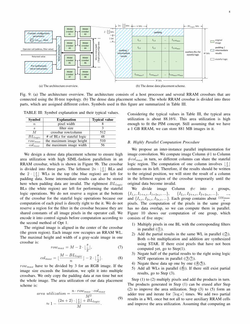
Figure 9a depicts the architecture for image processing, inwhich each RRAM crossbar plays two roles at the same time,as both a storage unit and a computation unit. Images arestored and processed in the same crossbars with little datatransfer. The area and offset of the computation region inone crossbar are determined by the global crossbar config-uration parameters. Multiple RRAM crossbars are connectedusing the H-tree topology. Data can be transferred betweenadjacent arrays via high speed links. We store each image inseveral contiguous crossbars, and thus, different images can beprocessed in parallel without I/O conflicts. It is able to storea large number of images in a single chip due to the highdensity of RRAM, and the total parallelism is considerable.
The image processing functions are pre-synthesized to one-line control signals. Once the host processor receives anoperator call that contains the image address and the filtervalue, it first writes the padding data in each crossbar. Forbig images stored in multiple crossbars, convolution of pixelson the border of sub images requires padding pixels in theadjacent crossbars. Then, it fills in the control signals with thefilter values and assigns parallelism according to the imagesize. Finally, it dispatches the instantiated control signals tothe corresponding crossbar(s).
8
Crossbar configuration parameters
( !"
, 𝑐𝑜𝑙&'()* , bias)
Host
pro
cess
or
RRAM crossbar
#1
RRAM crossbar
#3
RRAM crossbar
#4
RRAM crossbar
#2
RRAM crossbar
#5
RRAM crossbar
#7
RRAM crossbar
#8
RRAM crossbar
#6Pre-synthesized
micro-instructions
Operator call (address, filter value)
Returned value
…
…
Mic
ro-in
stru
ctio
ns/ D
uplic
ated
imag
e da
ta
padding / intermediate
results
padding
auxiliary BLs for stateful logic
𝐼,,, 𝐼,," … 𝐼,,*'&./0
𝐼",, 𝐼"," … 𝐼",*'&./0
… … … …
𝐼1'2./0,, 𝐼1'2./0," … 𝐼1'2./0,*'&./0
2𝑛 ⋅ 6"
bits 𝑛 bits 𝐵𝐿&'()* bits
𝑀 bits
𝑀 bits
original image
padding / intermediate results
stateful logic
2 ⋅ !"
bits
1 bit
(a) The architecture overview. (b) The dense data placement scheme.
Fig. 9: (a) The architecture overview. The architecture consists of a host processor and several RRAM crossbars that areconnected using the H-tree topology. (b) The dense data placement scheme. The whole RRAM crossbar is divided into threeparts, which are assigned different colors. Symbols used in this figure are summarized in Table III.
TABLE III: Symbol explanation and their typical values.
Symbol Explanation Typical valuen pixel width 8s filter size 3M crossbar row/column 512
BLlogic # of BLs for stateful logic 48rowmax the maximum image height 510colmax the maximum image width 56
We design a dense data placement scheme to ensure higharea utilization with high SIML-fashion parallelism in anRRAM crossbar, which is shown in Figure 9b. The crossbaris divided into three parts. The leftmost 2n · b s2c BLs andthe 2 · b s2c WLs in the top (the blue region) are left forpadding data. Some intermediate results can also be storedhere when padding data are invalid. The rightmost BLlogicBLs (the white region) are left for performing the statefullogic operations. We do not reserve a region at the bottomof the crossbar for the stateful logic operations because ourcomputation of each pixel is directly right to the it. We do notreserve a region for the filter in the crossbar because they areshared constants of all image pixels in the operator call. Weencode it into control signals before computation according tothe second method of Opt 1.
The original image is aligned in the center of the crossbar(the green region). Each image row occupies an RRAM WL.The maximal height and width of a gray-scale image in onecrossbar is:
rowmax =M − 2 · bs2c, (7)
colmax = bM −BLlogicn
c − 2 · bs2c. (8)
rowmax have to be divided by 3 for an RGB image. If theimage size exceeds the limitation, we split it into multiplecrossbars. We only copy the padding data at run time but notthe whole image. The area utilization of our data placementscheme is:
area utilization =n · rowmax · colmax
M2
≈ 1−(2n+ 2) · b s2c+BLlogic
M.
(9)
Considering the typical values in Table III, the typical areautilization is about 88.16%. This area utilization is highenough to fit the PIM concept. Still assuming that we havea 1 GB RRAM, we can store 881 MB images in it.
B. Highly Parallel Computation Procedure
We propose an inter-instance parallel implementation forimage convolution. We compute image Column #1 to Column#colmax in turn, so different columns can share the statefullogic region. The computation of one column involves b s2ccolumns on its left. Therefore, if the results should be writtento the original position, we will store the result of a columnin the leftmost region of the crossbar temporarily until theoriginal data become invalid.
We divide image Column #c into s groups,{I1,c, I1+s,c, I1+2s,c, ...}, {I2,c, I2+s,c, I2+2s,c, ...}, ...,and {Is,c, I2s,c, I3s,c, ...}. Each group contains about rowmax
spixels. The computation of the pixels in the same grouphas no data overlap, so we can compute them in parallel.Figure 10 shows our computation of one group, whichconsists of five steps:
1) Multiply pixels in one BL with the corresponding filtersin parallel ( 1©).
2) Add the partial results in the same WL in parallel ( 2©).Both n-bit multiplication and addition are synthesizedusing STAR. If there exist pixels that have not beencomputed yet, go to Step(1).
3) Negate half of the partial results to the right using logicNOT operations in parallel ( 3© 7©).
4) Negate these data up one by one ( 4© 5©).5) Add all WLs in parallel ( 6©). If there still exist partial
results, go to Step (3).
Step (1) to (2) multiply pixels and add the products in turn.The products generated in Step (1) can be erased after Step(2) to improve the area utilization. Step (3) to (5) form anadder tree and iterate for dlog se times. We add two partialresults in a WL once but not all to save auxiliary RRAM cellsand improve the area utilization. Assuming that computing an

9
𝐼"," 𝐼",$ 𝐼",% 𝐼"," ⋅ 𝑓"," 𝐼",$ ⋅ 𝑓",$ … (𝐼",) ⋅ 𝑓",)
%
)*"
( 𝐼$,) ⋅ 𝑓$,)
%
)*"
((𝐼+,) ⋅ 𝑓+,)
%
)*"
$
+*"
𝐼$," 𝑰𝟐,𝟐 𝐼$,% 𝐼$," ⋅ 𝑓$," 𝐼$,$ ⋅ 𝑓$,$ … (𝐼$,) ⋅ 𝑓$,)
%
)*"
−( 𝐼$,) ⋅ 𝑓$,)
%
)*"
…
𝐼%," 𝐼%,$ 𝐼%,% 𝐼%," ⋅ 𝑓%," 𝐼%,$ ⋅ 𝑓%,$ … (𝐼%,) ⋅ 𝑓%,)%
)*"
… …
𝐼/," 𝐼/,$ 𝐼/,% 𝐼/," ⋅ 𝑓"," 𝐼/,$ ⋅ 𝑓",$ … (𝐼/,) ⋅ 𝑓/,)
%
)*"
( 𝐼0,) ⋅ 𝑓0,)
%
)*"
((𝐼+,) ⋅ 𝑓+,)
%
)*"
0
+*/
𝐼0," 𝑰𝟓,𝟐 𝐼0,% 𝐼0," ⋅ 𝑓$," 𝐼0,$ ⋅ 𝑓$,$ … (𝐼0,) ⋅ 𝑓0,)%
)*"
−( 𝐼0,) ⋅ 𝑓0,)%
)*"
…
𝐼2," 𝐼2,$ 𝐼2,% 𝐼2," ⋅ 𝑓$," 𝐼2,$ ⋅ 𝑓%,$ … (𝐼2,) ⋅ 𝑓2,)
%
)*"
… …
①
①
①
①
①
①
③
③
④
⑤
⑥
⑥
⑦
⑦
②
②
②
②
②
②
Fig. 10: One group computation. This figure takes s = 3 as an example. I2,2 and I5,2 are being computed. Some intermediateresults of the stateful logic operations are not shown. Although the auxiliary area for stateful logic is much larger than the onefor one group, different groups (or columns) can reuse the same region for stateful logic to keep a high area utilization.
addition in series takes cycle+ cycles, the total cycles fromStep (2) to (4) are:
cycleinter ≈dlog se∑i=1
(n+ browmaxs
c · b s2ic+ cycle+). (10)
The i-th iteration adds b s2i c partial sums of each target pixel.The degree of parallelism reaches O(M) at most of the steps.
We select the global BLlogic for a crossbar:
BLlogic = max{cell×,opt, cell+,opt}+ n. (11)
We can get cell×,opt and cell+,opt according to Equation 6 inOpt 2 of STAR. We have to compute at least two multiplica-tions in a WL and then add them, so we reserve n cells for theproduct computed first. The input of the multiplication is theoriginal image, so the coverInput option is false. The inputof the addition is the partial sums that will not be used in thefuture, so the coverInput option is true. BLlogic is positivelycorrelated to n, s, so we can get a higher area utilization underour dense data placement scheme with a smaller n, a smallers, and a bigger M .
Our computation procedure achieves a high area utilizationby fully reusing cells. We not only reuse cells during all n-bitadditions and multiplications but also reuse the whole statefullogic region among different groups and columns.
V. EXPERIMENTAL EVALUATION
We compare our work with previous works on stateful logicin this section. We first evaluate the general-purpose synthesisflow and focus on the scheduling algorithm. Then, we evaluateour implementation of image convolution. We only optimizethe shared constants in the image convolution but not inthe general-purpose comparison. We normalize the physicalparameters, e.g., technology node, crossbar size, operationlatency, in the comparison. The latency can be representedby the number of cycles, and the area can be represented bythe number of RRAM cells.
A. Synthesis Flow EvaluationIn Fig. 11, we compare STAR with seven other synthesis
flows listed in TABLE I previously, in the area utilization andthe throughput using three benchmark suites, ISCAS’85 [10],LgSynth’91 [16], and IWLS’93 [18]. Each previous synthesisflow uses one or more suites in the original publication.We support the four-input NOR operation additionally in theIWLS’93 benchmark, similarly to the previous works. Weevaluate two modes of STAR: ‘tradeoff mode’ makes a tradeoffbetween area utilization and throughput by using cellopt cells(α = 1) and setting coverInput = false; ‘Area-first mode’uses cellmin cells and can cover the input, so it has the highestarea utilization. TABLE IV lists the average area utilization ofSTAR on these benchmark suites.
Fig. 11a, 11c, 11e evaluates the area utilization. Our ‘area-first mode’ achieves 102.10%, 85.77%, 76.85%, 103.15%,103.78%, 72.91%, 33.03% more area utilization, comparedto Logic [9], SIMPLE [17], Scalable [11], Look-ahead [12],Staircase [13], SAID [14], SIMPLER [15], respectively. Forprevious synthesis flows, the area utilization of most cases isless than 50%. The intermediate variables and unused cellsoccupy most of the area. On contrary, the area utilizationof ‘area-first mode’ is usually larger than 80% and evenexceeds 100% in nine cases because the input and outputvariables share some cells. The ‘tradeoff mode’ also achievesa significant area utilization improvement.
STAR has less advantage in a few cases, e.g., 9sym andclip in IWLS’93, because of the complex operation graph.These cases have very few input and output variables and manyintermediate variables. Most variables have high fan-in andfan-out, so their erasePre sets are relatively large. We haveto store lots of intermediate variables in the RRAM crossbarduring execution.
As shown in Fig. 11b, 11d, 11f, our ‘area-first mode’achieves 9.83×, 6.65×, 69.33×, 82.46×, 318.42×, 17.42×,1.43× throughput (per crossbar) compared to Logic [9],

10
1%
3%
9%
27%
81%
c432 c499 c880 c1355 c1908 c2670 c3540 c5315 c6288 c7552
Area
util
izatio
n (lo
g sc
ale)
Logic Scalable Look-ahead StaircaseSAID SIMPLER Tradeoff mode Area-first mode
(a) Area utilization comparison using ISCAS’85.
0.01
0.03
0.09
0.27
0.81
c432 c499 c880 c1355 c1908 c2670 c3540 c5315 c6288 c7552
Norm
alize
d th
roug
hput
(log
scal
e)
Logic Scalable Look-ahead StaircaseSAID SIMPLER Tradeoff mode Area-first mode
(b) Throughput comparison using ISCAS’85.
1%
3%
9%
27%
81%
5xp1 clip cm150a cm162a cm163a misex1 parity x2
Area
util
izatio
n (lo
g sc
ale)
SIMPLE SIMPLER Tradeoff mode Area-first mode
(c) Area utilization comparison using LgSynth’91.
0.01
0.03
0.09
0.27
0.81
5xp1 clip cm150a cm162a cm163a misex1 parity x2
Norm
alize
d th
roug
hput
(log
scal
e)
SIMPLE SIMPLER Tradeoff mode Area-first mode
(d) Throughput comparison using LgSynth’91.
1%
3%
9%
27%
81%
9sym apex5 clip duke2 e64 inc misex3c rd73 sao2 vg2
Area
util
izatio
n(lo
g sc
ale)
Scalable SAID SIMPLER Tradeoff mode Area-first mode
(e) Area utilization comparison using IWLS’93.
0.01
0.03
0.09
0.27
0.81
9sym apex5 clip duke2 e64 inc misex3c rd73 sao2 vg2
Norm
alize
d th
roug
hput
(log
scal
e)
Scalable SAID SIMPLER Tradeoff mode Area-first mode
(f) Throughput comparison using IWLS’93.
Fig. 11: Synthesis flow evaluation using three benchmark suites. In (a)(c)(e), partial input and output variables may share thesame cells, so the area utilization of the ‘area-first mode’ can exceed 100%. In (b)(d)(f), the throughput of the ‘area-firstmode’ is normalized to 1. We ideally assume that previous flows can compute all of the instances in parallel. STAR achievessignificant area utilization and throughput improvement compared to previous flows.
TABLE IV: High area utilization of STAR (‘Area-first mode’).
Benchmark Work Area utilizationISCAS’85
STAR105.79%
LgSynth’91 93.80%IWLS’93 55.59%
SIMPLE [17], Scalable [11], Look-ahead [12], Staircase [13],SAID [14], SIMPLER [15], respectively. In fact, the actualthroughput gain can be much higher for two reasons. First, wefix the total area of each synthesis flow in this comparison,so the computation area of STAR is much less than that inother flows because of higher area utilization. Assuming thatour area utilization is α and the area utilization of a previouswork is β (α > β), the throughput gain have to be multipliedby 1−β
1−α if we fix the computation area of each synthesis flow.Second, the previous flows except SIMPLER cannot computeall of the instances in parallel, and the latency increases withthe instance number. The throughput gain have to be multipliedfor multiple instances. We just estimate an ideal situation forthem in the comparison as SIMPLER.
B. Scheduling Algorithm Evaluation
We evaluate our scheduling algorithm using the ISCAS’85benchmark, as shown in Fig. 12. We use the configurationof the ‘tradeoff mode’ in this figure. Fig. 12a evaluates the
area saving of the algorithm compared with the one withoutreusing. Our algorithm saves 83.20% area compared to theoriginal ABC synthesis result without reusing.
Fig. 12b evaluates the effect of different SETmaxs on thenumber of erasing operations. We obtain three conclusionsfrom this figure. First, the extra erasing operations inserted bythe scheduling algorithm has a small overhead. The averageerasing operation ratio is only 11.22% when SETmax = 10.It becomes 5.41% if we do not restrict SETmax. Second, thenumber of erasing operations increases slowly when decreas-ing SETmax. A smaller SETmax has less negative effect onthe total latency. Third, our algorithm does well for any givenSETmax. The minimal erasing operation ratio is 1
1+SETmax
(the dotted line in the figure) if we always erase SETmaxvariables once after they are computed. The average erasingoperation ratio of our algorithm is empirically less than twiceof the lower bound.
Fig. 12c evaluates the erased cell ratio on one cell, whichstays between 40% to 50%. Since the energy consumptionis proportional to the written cells, we can infer that theerasing operations consumes 40%-50% energy in the wholecomputation procedure. A cell is written by either an erasingoperation or a MAGIC operation. That is to say, the numberof erased cells is a little smaller than the number of MAGICoperations. In fact, a cell can be reused only after it is erased.

11
60%
70%
80%
90%
100%
c432 c499 c880 c1355 c1908 c2670 c3540 c5315 c6288 c7552
Area
savi
ng
(a) Area saving of the algorithm.
𝑒𝑟𝑎𝑠𝑖𝑛𝑔𝑜𝑝𝑒𝑟𝑎𝑡𝑖𝑜𝑛𝑠
𝑡𝑜𝑡𝑎𝑙𝑐𝑦𝑐𝑙𝑒𝑠
𝑆𝐸𝑇!"#
0%
4%
8%
12%
16%
10 15 20 25 30 INF
c432c499c880c1355c1908c2670c3540c5315c6288c7552lower bound
(b) Effect of different SETmaxs on the erasing operation ratio.
𝑒𝑟𝑎𝑠𝑒𝑑𝑐𝑒𝑙𝑙𝑠
𝑡𝑜𝑡𝑎𝑙𝑤𝑟𝑖𝑡𝑡𝑒𝑛𝑐𝑒𝑙𝑙𝑠
40%
42%
44%
46%
48%
50%
c432 c499 c880 c1355 c1908 c2670 c3540 c5315 c6288 c7552
(c) Erased cell ratio. If a cell is erased or written multiple times, werecord it multiple times.
Fig. 12: Scheduling algorithm evaluation.
For all synthesis flows (with or without the reusing strategy),they need to erase (or initialize) the cells for intermediatevariables before computing the new instance. If consideringthe cost of the initialization procedure, these flows erase asimilar number of cells as STAR and consume similar energyon erasing operations. They only differ in when and how toerase these cells, so they have different latency and throughput.
We also compare our scheduling algorithm with SIMPLER.Fig. 13 compares the minimal RRAM cells achieved by twoscheduling algorithms. When setting coverInput = false,our algorithm saves 16.06%, 33.19%, 9.24% cells on theISCAS’85, LgSynth’91, EPFL benchmarks, respectively. Ouralgorithm needs fewer cells on most of the cases. For the othercases where SIMPLER has got the near-optimal result, our al-gorithm can get the similar result. When setting coverInput =true, our algorithm saves 38.85%, 46.39%, 37.17% cells onthe ISCAS’85, LgSynth’91, EPFL benchmarks, respectively.The area saving from erasing the inputs depends on the netliststructure and varies among different cases.
Our algorithm also saves most of the erasing operationsand helps improve the throughput. For example, accordingto Fig. 14, our algorithm also saves 77.40% of the erasingoperations when the number of the RRAM cells is fixed tothe minimal cells of SIMPLER. Because the erasing operationsonly occupy a small part in the total computation procedure(see Fig. 12b), the throughput improvement is not obvious (seeFig. 11).
Our algorithm needs fewer cells and cycles because of
0
150
300
450
600
c432 c499 c880 c1355 c1908 c2670 c3540 c5315 c6288 c7552
Mim
imal
cells
SIMPLER STAR (coverInput = false) STAR (coverInput = true)
(a) ISCAS’85 benchmark.
0
10
20
30
40
50
5xp1 clip cm150a cm162a cm163a misex1 parity x2
Min
imal
cells
SIMPLER STAR (coverInput = false) STAR (coverInput = true)
(b) LgSynth’91 benchmark.
0
300
600
900
1200
adder arbiter bar calvc ctrl dec int2float max priority sinM
inim
al ce
lls
SIMPLER STAR (coverInput = false) STAR (coverInput = true)
(c) EPFL benchmark.
Fig. 13: Minimal cells of two scheduling algorithms.
0
50
100
150
200
250
adder arbiter bar calvc ctrl dec int2float max priority sin
Eras
ing
oper
atio
ns
SIMPLER STAR
Fig. 14: Erasing operations of two scheduling algorithms usingthe minimal cells of SIMPLER on the EPFL benchmark.
our better heuristic function. SIMPLER estimates the minimalnumber of cells required for the execution of one vertex in thecomputation graph by the Strahler number, which is intendedfor trees only. The estimation is static and may be incorrect if avertex has multiple successors. On contrary, the erasePre setin our algorithm can exactly represent the minimal variables tocompute before a vertex can be erased and dynamically adjustduring the algorithm execution.
C. Case Study Evaluation: Image Convolution
We compare our work with two MAGIC-based imageprocessing accelerator APIM [26] and IMAGING [19]. BothAPIM and IMAGING manually design the addition and mul-tiplication. We get the results of IMAGING by using limitedprecision multiplication proposed in its work.
As shown in Figure 15a, STAR achieves 78.36% and80.97% more area utilization on average over IMAGING andAPIM, respectively. STAR keeps a greater than 75% areautilization in all cases while the other two works are smaller

12
0%
20%
40%
60%
80%
100%
3 5 7 9
Area
util
izatio
n
Filter size
STARIMAGINGAPIM
(a) Area utilization.
0.0
0.2
0.4
0.6
0.8
1.0
3 5 7 9
Thro
ughp
ut
(bit
/ cyc
le)
Filter size
STARIMAGINGAPIM
(b) Throughput (per crossbar).
Fig. 15: Convolution comparison with different filter sizes. Thecrossbar size is 512×512.
0
400
800
1200
8 16 32 64
Area
(RRA
M c
ells)
Pixel width
IMAGINGSTAR (Opt 2)STAR (Opt 1+2)
(a) Opt 1+2 achieves a 53.28% area saving.
100
1000
10000
100000
8 16 32 64
Late
ncy (
cycl
es)
Pixel width
IMAGINGSTAR (Opt 2)STAR (Opt 1+2)
(b) Opt 1+2 achieves a 1.10× speedup.
Fig. 16: Limited precision multiplication comparison. Opt 1:encode the filter into control signals. Opt 2: reuse RRAM cells.
than 10%. As shown in Figure 15b, STAR achieves a 1.48×and 8.53× higher throughput per crossbar than IMAGING andAPIM, respectively. The area utilization and throughput ofthree works decreases with the increase of the filter size asthe computation becomes more and more complex.
We make a detailed comparison between our implemen-tation and the state-of-the-art work IMAGING. Figure 16compares the implementation of the most complex functionin convolution, limited-precision multiplication, in which theinput and output have the same pixel width. According toFigure 16a, our implementation saves 56.17% area. Twooptimization strategies contribute 11.29% and 44.88%, respec-tively. According to Figure 16b, our implementation achievesan up to 1.10× speedup besides significant area saving.
Table V and Fig. 17 gives a detailed analysis for the filtersize s = 3. The area utilization improvement comes from twoparts. First, our rowmax is 3× over IMAGING, as IMAGING
TABLE V: Detailed analysis when the filter size s = 3. Thecrossbar size is 512×512.
Work IMAGING STAR
Image size rowmax 170 510colmax 8 56
Area utilization 8.10% 88.16%
Data transfer /pixel (bit)
duplication 24 0filter 4.24 0
padding 1.06 0.31Execution cycles / pixel 11.03 9.63Throughput (bit / cycle) 0.57 0.83
input / output8%
input copies21%
filter5%
intermediate variables
66%
(a) Area breakdown in IMAGING.
input / output87%
intermediate variables13%
(b) Area breakdown in STAR.
Fig. 17: Area breakdown when the filter size s = 3. Thecrossbar size is 512×512.
duplicates the (negative) image for 2s = 6 times to computes adjacent pixels in parallel. Second, our colmax is 3.3× overIMAGING, as IMAGING stores rowmax filters, colmax partialsums, and many other intermediate variables simultaneouslyin a WL. The area utilization gap expands gradually with theincrease of the filter size.
The throughput improvement also comes from two parts.First, our data placement scheme saves most of the datatransfer. Only a few padding data will be written into thecrossbar during initialization. Here assumes that the computa-tion crossbars and the storage crossbars are adjacent and thedata transfer speed is one image row / cycle. The initializationoverhead will increase by about an order of magnitude or moreif the original image is farther away [27], i.e., outside the bankor the chip. Second, our MAGIC execution achieves a 1.15×speedup over IMAGING on the same input image. Both worksexploit the inter-instance parallel manner, so the total speedupin MAGIC execution mainly comes from that in series.
VI. RELATED WORK
Recent works implement several stateful logic operationsin the RRAM crossbar, e.g., IMP [4], NOR [5], and corre-sponding synthesis flows propose to fully utilize the massive
13
parallelism of the stateful logic. SIMPLE [17] minimizesthe latency by solving an Integer Linear Programming (ILP)problem but has exponential time complexity. The followingworks design some heuristic algorithms to find an approximatesolution. For example, Staircase [13] performs WL and BLoperations alternately using a staircase structure to reduceextra data copy. SAID [14] represents the logic function byLook-Up Tables (LUTs) and then map the LUTs onto thecrossbar to maximize LUT-level parallelism. However, theseheuristic synthesis flows neglect the use of RRAM for datastorage and have ultra-low area utilization. SIMPLER [15]tries to improve area utilization by reusing RRAM cells, butits scheduling algorithm cannot get the optimal result.
Some works map the function onto the RRAM crossbarmanually. For example, APIM [26] designs a carry save treestructure for fast addition and multiplication. IMAGING [28],[19] proposes four algorithms for efficient execution of FixedPoint (FiP) multiplication using MAGIC gates under dif-ferent constraints and then accelerate three common imageprocessing applications. Although these designs achieve highthroughput, their mapping methods are only optimized for aparticular application and cannot apply to other applications.
Some studies perform computation on RRAM without thenon-volatile stateful logic. For example, Pinatubo [20] andPIMA [29] implements bulk bitwise operations by redesigningthe read circuitry. Besides digital fashion, RRAM also supportsmatrix-vector multiplication in the analog fashion, which hasbeen exploited to accelerate convolutional neural networks(CNN) [30], [31], [32] and binary neural networks (BNN) [33].Despite low latency, it lacks in accuracy and suffers from highvariation, which restricts its scope of application. Moreover,power consumption from additional AD-conversion and I/Oscannot be ignored [34].
VII. CONCLUSION
In this work, we propose STAR, a synthesis flow forstateful logic in RRAM, to improve the area utilization withoutthroughput loss. In STAR, we first reduce the area for primaryinputs by not copying inputs, encoding the shared constantsinto the control signals, and erasing invalid inputs duringthe computation procedure. Then, we propose a schedulingalgorithm to get the computation sequence with minimalerasing operations. Experimental evaluation shows that we canachieve ultra-high area utilization and improve the throughputin various benchmarks.
REFERENCES
[1] J. Backus, “Can programming be liberated from the von neumann style?a functional style and its algebra of programs,” Communications of theACM, vol. 21, no. 8, pp. 613–641, 1978.
[2] H. Akinaga and H. Shima, “Resistive Random Access Memory(ReRAM) Based on Metal Oxides,” Proceedings of the IEEE, vol. 98,no. 12, pp. 2237–2251, 2010.
[3] T.-y. Liu, T. H. Yan, R. Scheuerlein, Y. Chen, J. K. Lee, G. Balakrishnan,G. Yee, H. Zhang, A. Yap, J. Ouyang et al., “A 130.7-mm2 2-Layer 32-Gb ReRAM Memory Device in 24-nm Technology,” IEEE Journal ofSolid-State Circuits, vol. 49, no. 1, pp. 140–153, 2014.
[4] J. Borghetti, G. S. Snider, P. J. Kuekes, J. J. Yang, D. R. Stewart, andR. S. Williams, “‘Memristive’ switches enable ‘stateful’logic operationsvia material implication,” Nature, vol. 464, no. 7290, p. 873, 2010.
[5] S. Kvatinsky, D. Belousov, S. Liman, G. Satat, N. Wald, E. G. Friedman,A. Kolodny, and U. C. Weiser, “MAGIC–Memristor-aided logic,” IEEETrans. Circuits Syst. II, Exp. Briefs, vol. 61, no. 11, pp. 895–899, 2014.
[6] P. Huang, J. Kang, Y. Zhao, S. Chen, R. Han, Z. Zhou, Z. Chen, W. Ma,M. Li, L. Liu et al., “Reconfigurable nonvolatile logic operations inresistance switching crossbar array for large-scale circuits,” AdvancedMaterials, vol. 28, no. 44, pp. 9758–9764, 2016.
[7] S. Gupta, M. Imani, and T. Rosing, “Felix: Fast and energy-efficientlogic in memory,” in Int’l Conf. on Computer-Aided Design (ICCAD),2018.
[8] F. Wang, G. Luo, G. Sun, J. Zhang, P. Huang, and J. Kang, “ParallelStateful Logic in RRAM: Theoretical Analysis and Arithmetic Design,”in Application-specific Systems, Architectures and Processors. IEEE,2019.
[9] N. Talati, S. Gupta, P. Mane, and S. Kvatinsky, “Logic design withinmemristive memories using memristor-aided loGIC (MAGIC),” IEEETrans. Nanotechnol., vol. 15, no. 4, pp. 635–650, 2016.
[10] F. Brglez and H. Fujiwara, “A Neutral Netlist of 10 CombinationalBenchmark Circuits and a Target Translator in Fortran,” in Int’l Symp.on Circuits and Systems (ISCAS). IEEE Press, Piscataway, N.J., 1985,pp. 677–692.
[11] R. Gharpinde, P. L. Thangkhiew, K. Datta, and I. Sengupta, “A scalablein-memory logic synthesis approach using memristor crossbar,” IEEETrans. on Very Large Scale Integration (VLSI) Systems, vol. 26, no. 2,pp. 355–366, 2018.
[12] D. N. Yadav, P. L. Thangkhiew, and K. Datta, “Look-ahead mappingof boolean functions in memristive crossbar array,” Integration, vol. 64,pp. 152–162, 2019.
[13] A. Zulehner, K. Datta, I. Sengupta, and R. Wille, “A staircase structurefor scalable and efficient synthesis of memristor-aided logic,” in Asiaand South Pacific Design Automation Conf. (ASP-DAC). ACM, 2019,pp. 237–242.
[14] V. Tenace, R. G. Rizzo, D. Bhattacharjee, A. Chattopadhyay, and A. Cal-imera, “Said: A supergate-aided logic synthesis flow for memristivecrossbars,” in Design, Automation, and Test in Europe (DATE). IEEE,2019, pp. 372–377.
[15] R. Ben-Hur, R. Ronen, A. Haj-Ali, D. Bhattacharjee, A. Eliahu, N. Peled,and S. Kvatinsky, “Simpler magic: Synthesis and mapping of in-memorylogic executed in a single row to improve throughput,” IEEE Trans.Comput.-Aided Design Integr. Circuits Syst., 2019.
[16] S. Yang, Logic synthesis and optimization benchmarks user guide:version 3.0. Microelectronics Center of North Carolina (MCNC), 1991.
[17] R. B. Hur, N. Wald, N. Talati, and S. Kvatinsky, “SIMPLE MAGIC:Synthesis and In-memory MaPping of Logic Execution for Memristor-Aided loGIC,” in Int’l Conf. on Computer-Aided Design (ICCAD).IEEE, 2017, pp. 225–232.
[18] K. McElvain, “Iwls’93 benchmark set: Version 4.0,” in Distributedas part of the MCNC International Workshop on Logic Synthesis’ 93benchmark distribution, 1993, pp. 1–6.
[19] A. Haj-Ali, R. Ben-Hur, N. Wald, R. Ronen, and S. Kvatinsky,“IMAGING-In-Memory AlGorithms for Image processiNG,” IEEETrans. Circuits Syst. II, Exp. Briefs, vol. 65, no. 12, pp. 4258–4271,2018.
[20] S. Li, C. Xu, Q. Zou, J. Zhao, Y. Lu, and Y. Xie, “Pinatubo: Aprocessing-in-memory architecture for bulk bitwise operations in emerg-ing non-volatile memories,” in Design Automation Conf. (DAC), 2016,pp. 1–6.
[21] S.-S. Sheu, M.-F. Chang, K.-F. Lin, C.-W. Wu, Y.-S. Chen, P.-F. Chiu,C.-C. Kuo, Y.-S. Yang, P.-C. Chiang, W.-P. Lin et al., “A 4Mb embeddedSLC resistive-RAM macro with 7.2 ns read-write random-access timeand 160ns MLC-access capability,” in Int’l Solid-State Circuits Conf.(ISSCC), 2011.
[22] L. Xu, L. Bao, T. Zhang, K. Yang, Y. Cai, Y. Yang, and R. Huang,“Nonvolatile memristor as a new platform for non-von Neumann com-puting,” in Int’l Conf. on Solid-State and Integrated Circuit Technology(ICSICT), 2018.
[23] B. L. SYNTHESIS, “Abc: a system for sequential synthesis and verifi-cation, release 70930,” 2007.
[24] C. Xu, D. Niu, N. Muralimanohar, R. Balasubramonian, T. Zhang,S. Yu, and Y. Xie, “Overcoming the challenges of crossbar resistivememory architectures,” in Int’l Symp. on High-Performance ComputerArchitecture (HPCA). IEEE, 2015, pp. 476–488.
[25] G. J. Chaitin, M. A. Auslander, A. K. Chandra, J. Cocke, M. E. Hopkins,and P. W. Markstein, “Register allocation via coloring,” Computerlanguages, vol. 6, no. 1, pp. 47–57, 1981.

14
[26] M. Imani, S. Gupta, and T. Rosing, “Ultra-efficient processing in-memory for data intensive applications,” in Design Automation Conf.(DAC). ACM, 2017, p. 6.
[27] N. Talati, A. H. Ali, R. B. Hur, N. Wald, R. Ronen, P.-E. Gaillardon,and S. Kvatinsky, “Practical challenges in delivering the promises ofreal processing-in-memory machines,” in Design, Automation, and Testin Europe (DATE). IEEE, 2018, pp. 1628–1633.
[28] A. Haj-Ali, R. Ben-Hur, N. Wald, and S. Kvatinsky, “Efficient algorithmsfor in-memory fixed point multiplication using magic,” in Int’l Symp.on Circuits and Systems (ISCAS). IEEE, 2018, pp. 1–5.
[29] S. Angizi, Z. He, and D. Fan, “Pima-logic: a novel processing-in-memory architecture for highly flexible and energy-efficient logic com-putation,” in Design Automation Conf. (DAC). ACM, 2018, p. 162.
[30] P. Chi, S. Li, C. Xu, T. Zhang, J. Zhao, Y. Liu, Y. Wang, and Y. Xie,“Prime: A novel processing-in-memory architecture for neural networkcomputation in reram-based main memory,” ACM SIGARCH Comput.Archit. News, vol. 44, no. 3, pp. 27–39, 2016.
[31] A. Shafiee, A. Nag, N. Muralimanohar, R. Balasubramonian, J. P. Stra-chan, M. Hu, R. S. Williams, and V. Srikumar, “Isaac: A convolutionalneural network accelerator with in-situ analog arithmetic in crossbars,”in Int’l Symp. on Computer Architecture (ISCA). IEEE Press, 2016,pp. 14–26.
[32] L. Song, X. Qian, H. Li, and Y. Chen, “Pipelayer: A pipelined reram-based accelerator for deep learning,” in Int’l Symp. on High-PerformanceComputer Architecture (HPCA). IEEE, 2017, pp. 541–552.
[33] X. Sun, S. Yin, X. Peng, R. Liu, J.-s. Seo, and S. Yu, “Xnor-rram:A scalable and parallel resistive synaptic architecture for binary neuralnetworks,” in Design, Automation, and Test in Europe (DATE). IEEE,2018, pp. 1423–1428.
[34] C. Liu, B. Yan, C. Yang, L. Song, Z. Li, B. Liu, Y. Chen, H. Li, Q. Wu,and H. Jiang, “A spiking neuromorphic design with resistive crossbar,”in Design Automation Conf. (DAC), 2015, pp. 1–6.
Feng Wang Feng Wang is a PhD student in theDepartment of Computer Science at Peking Univer-sity. His research interests include NVM and PIM.Wang has a BS in computer science from PekingUniversity. Contact him at [email protected].
Guojie Luo Guojie Luo is an associate professor inthe Department of Computer Science at Peking Uni-versity. His current research interests include elec-tronic design automation, heterogeneous computingwith FPGAs and emerging devices, and medicalimaging analytics. Luo received a PhD in ComputerScience from the University of California, Los An-geles. Contact him at [email protected].
Guangyu Sun Guangyu Sun is an associate pro-fessor in the Department of Computer Science atPeking University. His current research interestsinclude energy-efficient memory architectures, stor-age system optimization for new devices and ac-celeration systems for deep learning applications.Sun received a PhD in Computer Science fromThe Pennsylvania State University. Contact him [email protected].
Jiaxi Zhang Jiaxi Zhang is a PhD student in theDepartment of Computer Science at Peking Univer-sity. His research interests include EDA and FPGAacceleration. Zhang has a BS in microelectronicsfrom Peking University. Contact him at [email protected].
Jinfeng Kang Jinfeng Kang is now a Full Profes-sor of Electronics Engineering Computer ScienceSchool in Peking University. His research interestis to explore novel device concepts, structures, ma-terials, circuits, and the system architectures forthe applications of future computing and data stor-age systems. His accomplishments focus on theRRAM technology and applications. Contact him [email protected].
Yuhao Wang Yuhao Wang is a Ph.D. from NanyangTechnological University, Singapore. He is now withAlibaba Damo Academy as a research scientist. Hisresearch interests mainly lie in the intersection ofemerging non-volatile memory, processing in mem-ory architecture and hardware/algorithm co-designs.He has authored or co-authored two monographs,16 scientific publications and holds 2 US patents.Contact him at [email protected].
Dimin Niu Dimin Niu is a research scientist inthe Computing Technology Lab of Alibaba DAMOAcademy. Prior to joining Alibaba, he was a staffmemory architecture in Memory Solutions Lab atSamsung Semiconductor Inc. His current researchinterests include computer architecture, memory ar-chitecture, storage system, process-in-memory, anddomain specific architectures. Niu received a PhD inComputer Science from the Pennsylvania State Uni-versity. Contact him at [email protected].
Hongzhong Zheng Hongzhong Zheng is a leadingresearch scientist in field of new memory and stor-age system, processing in memory technology andarchitecture in the Computing Technology Lab ofAlibaba DAMO Academy. Prior to joining Alibaba,he was a director in Memory Solutions Lab atSamsung Semiconductor Inc. His current researchinterests include computer architecture, memory ar-chitecture, storage system, process-in-memory, anddomain specific architectures. Mr. Zheng received aPhD in Computer Engineering from the University
of Illinois at Chicago. Contact him at [email protected].