start condens kis 20114898 - schede-tecniche.it · 3 start condens 25 - 29 kis it en hu in alcune...
TRANSCRIPT

IT - MANUALE PER L’INSTALLATORE E L’UTENTE
EN - INSTALLER AND USER MANUAL
HU - TELEPÍTŐI ÉS FELHASZNÁLÓI KÉZIKÖNYV
Start Condens 25 - 29 Kis
2
START CONDENS 25 - 29 Kis
START CONDENS Kis boiler complies with basic requirements of the following Directives:- Gas directive 2009/142/EC;- Efficiency directive: Article 7(2) and Annex III of directive 92/42/EEC;- Electromagnetic compatibility directive 2004/108/EC;- Low-voltage directive 2006/95/EC;- Directive 2009/125/EC Ecodesign for energy-using appliances;- Directive 2010/30/EU Indication by labelling of the consumption of
energy by energy-related products;- Delegated Regulation (EU) No. 811/2013;- Delegated Regulation (EU) No. 813/2013;- Delegated Regulation (EU) No. 814/2013.
Az START CONDENS Kis kazán teljesíti az alábbi irányelvek lényegi követelményeit:- 2009/142/EK gáz irányelv;- Diretiva de rendimento: Artigo 7(2) e no Anexo III da diretiva 92/42/CEE;- 2004/108/EK irányelv az elektromágneses összeférhetőségről;- 2006/95/EK irányelv a kisfeszültségű berendezésekről;- 2009/125/EK irányelv az energiafelhasználó termékek környezetbarát
tervezéséről;- 2010/30/EU irányelv az energiával kapcsolatos termékek energia-
fogyasztásának címkézéssel történő jelöléséről;- 811/2013/EU felhatalmazáson alapuló rendelet;- 813/2013/EU felhatalmazáson alapuló rendelet;- 814/2013/EU felhatalmazáson alapuló rendelet.
La caldaia START CONDENS Kis è conforme ai requisiti essenziali delle seguenti Direttive:- Direttiva gas 2009/142/CE;- Direttiva Rendimenti Articolo 7(2) e Allegato III della 92/42/CEE.- Direttiva Compatibilità Elettromagnetica 2004/108/CE;- Direttiva bassa tensione 2006/95/CE;- Direttiva 2009/125/CE Progettazione ecocompatibile dei prodotti
connessi all’energia;- Direttiva 2010/30/UE Indicazione del consumo di energia mediante
etichettatura;- Regolamento Delegato (EU) N. 811/2013;- Regolamento Delegato (EU) N. 813/2013;- Regolamento Delegato (EU) N. 814/2013.
04760694CL6033
EN
HU
IT

3
START CONDENS 25 - 29 Kis
IT
EN
HU
In alcune parti del libretto sono utilizzati i simboli:
9 ATTENZIONE = per azioni che richie-dono particolare cautela ed adeguata preparazione.
0 DIVIETO = per azioni che NON DE-VONO essere assolutamente esegui-te. Parte destinata anche all’utente.
AvvertenzaQuesto manuale istruzioni contiene dati e informazioni destinati sia all’utente che all’installatore. Nello specifico si informa che l’utente, per l’utilizzo dell’apparec-chio, deve riferirsi ai capitoli:• Avvertenze e sicurezze• Messa in servizio• Manutenzione• Display e codici anomalie
0 L’utente non deve intervenire sui di-spositivi di sicurezza, sostituire parti del prodotto, manomettere o tentare di riparare l’apparecchio. Queste ope-razioni devono essere demandate esclusivamente a personale profes-sionalmente qualificato.
9 Il costruttore non è responsabile di eventuali danni causati dall’inosser-vanza di quanto sopra riportato e/o del mancato rispetto delle normative vigenti.
In some parts of the booklet, some sym-bols are used:
9 WARNING = for actions requiring special care and adequate prepara-tion.
0 PROHIBITED = for actions THAT MUST NOT be performed. Section destined for user also.
WarningThis instructions manual contains data and information for both the user and the installer. Specifically, note that the user, for the use of the appliance, must refer to chapters:• Warnings and safety• Commissioning• Maintenance• Display and fault codes
0 The user must not perform operations on the safety devices, replacing parts of the product, tamper with or attempt to repair the appliance. These oper-ations must be entrusted exclusively professionally qualified personnel.
9 The manufacturer is not liable for any damage caused by the non-obser-vance of the above and/or the failure to comply with the regulations.
A kézikönyvben helyenként az alábbi szimbólumok szerepelnek:
9 FIGYELEM = a művelet különös fi-gyelmet és körültekintést, valamint kellő felkészültséget igényel.
0 TILOS = olyan művelet, amit szigorú-an TILOS végrehajtani. A felhasználónak is szóló rész.
FigyelmeztetésEz a kézikönyv mind a felhasználó, mind a telepítő számára tartalmaz adatokat és információkat. Tájékoztatjuk a felhaszná-lót, hogy a készülék használatához a kö-vetkező fejezeteket kell tanulmányoznia:• Általános tudnivalók és biztonsági elő-
írások• Üzembe helyezés• Karbantartás
• Rendellenességek kódjai és kijelzése 0 A felhasználónak tilos módosítania a
biztonsági eszközökön, kicserélni a termék egyes részeit, megváltoztatni vagy megpróbálni megjavítani a ké-szüléket. Ezeket a műveleteket kizá-rólag szakképzett személy végezheti el.
9 A készülék gyártója nem vállal fele-lősséget a fentiek és/vagy a hatályos előírások be nem tartásáért.
4
START CONDENS 25 - 29 Kis
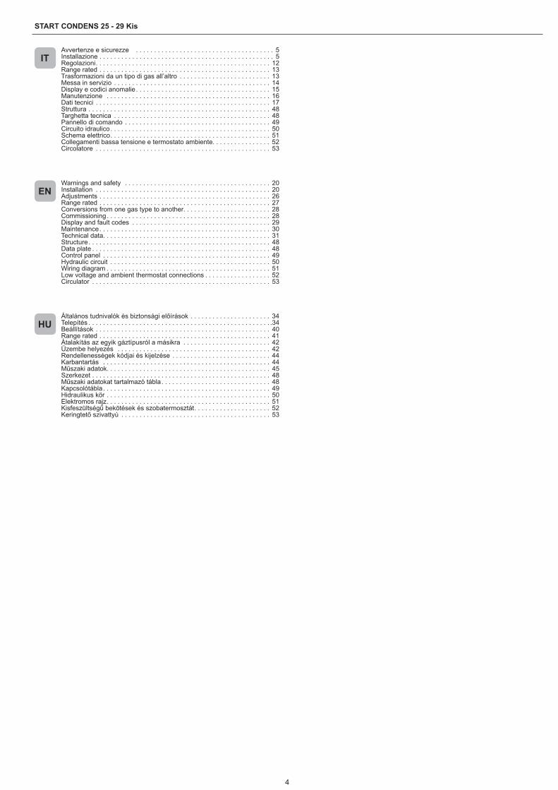
Avvertenze e sicurezze . . . . . . . . . . . . . . . . . . . . . . . . . . . . . . . . . . . . . . 5Installazione . . . . . . . . . . . . . . . . . . . . . . . . . . . . . . . . . . . . . . . . . . . . . . . . 5Regolazioni. . . . . . . . . . . . . . . . . . . . . . . . . . . . . . . . . . . . . . . . . . . . . . . . 12Range rated . . . . . . . . . . . . . . . . . . . . . . . . . . . . . . . . . . . . . . . . . . . . . . . 13Trasformazioni da un tipo di gas all’altro . . . . . . . . . . . . . . . . . . . . . . . . . 13Messa in servizio . . . . . . . . . . . . . . . . . . . . . . . . . . . . . . . . . . . . . . . . . . . 14Display e codici anomalie . . . . . . . . . . . . . . . . . . . . . . . . . . . . . . . . . . . . . 15Manutenzione . . . . . . . . . . . . . . . . . . . . . . . . . . . . . . . . . . . . . . . . . . . . . 16Dati tecnici . . . . . . . . . . . . . . . . . . . . . . . . . . . . . . . . . . . . . . . . . . . . . . . . 17Struttura . . . . . . . . . . . . . . . . . . . . . . . . . . . . . . . . . . . . . . . . . . . . . . . . . . 48Targhetta tecnica . . . . . . . . . . . . . . . . . . . . . . . . . . . . . . . . . . . . . . . . . . . 48Pannello di comando . . . . . . . . . . . . . . . . . . . . . . . . . . . . . . . . . . . . . . . . 49Circuito idraulico. . . . . . . . . . . . . . . . . . . . . . . . . . . . . . . . . . . . . . . . . . . . 50Schema elettrico. . . . . . . . . . . . . . . . . . . . . . . . . . . . . . . . . . . . . . . . . . . . 51Collegamenti bassa tensione e termostato ambiente. . . . . . . . . . . . . . . . 52Circolatore . . . . . . . . . . . . . . . . . . . . . . . . . . . . . . . . . . . . . . . . . . . . . . . . 53
Általános tudnivalók és biztonsági előírások . . . . . . . . . . . . . . . . . . . . . . 34Telepítés . . . . . . . . . . . . . . . . . . . . . . . . . . . . . . . . . . . . . . . . . . . . . . . . . . .34Beállítások . . . . . . . . . . . . . . . . . . . . . . . . . . . . . . . . . . . . . . . . . . . . . . . . 40Range rated . . . . . . . . . . . . . . . . . . . . . . . . . . . . . . . . . . . . . . . . . . . . . . . 41Átalakítás az egyik gáztípusról a másikra . . . . . . . . . . . . . . . . . . . . . . . . 42Üzembe helyezés . . . . . . . . . . . . . . . . . . . . . . . . . . . . . . . . . . . . . . . . . . 42Rendellenességek kódjai és kijelzése . . . . . . . . . . . . . . . . . . . . . . . . . . . 44Karbantartás . . . . . . . . . . . . . . . . . . . . . . . . . . . . . . . . . . . . . . . . . . . . . . 44Műszaki adatok. . . . . . . . . . . . . . . . . . . . . . . . . . . . . . . . . . . . . . . . . . . . . 45Szerkezet . . . . . . . . . . . . . . . . . . . . . . . . . . . . . . . . . . . . . . . . . . . . . . . . . 48Műszaki adatokat tartalmazó tábla. . . . . . . . . . . . . . . . . . . . . . . . . . . . . . 48Kapcsolótábla. . . . . . . . . . . . . . . . . . . . . . . . . . . . . . . . . . . . . . . . . . . . . . 49Hidraulikus kör . . . . . . . . . . . . . . . . . . . . . . . . . . . . . . . . . . . . . . . . . . . . . 50Elektromos rajz. . . . . . . . . . . . . . . . . . . . . . . . . . . . . . . . . . . . . . . . . . . . . 51Kisfeszültségű bekötések és szobatermosztát. . . . . . . . . . . . . . . . . . . . . 52Keringtető szivattyú . . . . . . . . . . . . . . . . . . . . . . . . . . . . . . . . . . . . . . . . . 53
Warnings and safety . . . . . . . . . . . . . . . . . . . . . . . . . . . . . . . . . . . . . . . . 20Installation . . . . . . . . . . . . . . . . . . . . . . . . . . . . . . . . . . . . . . . . . . . . . . . . 20Adjustments . . . . . . . . . . . . . . . . . . . . . . . . . . . . . . . . . . . . . . . . . . . . . . . 26Range rated . . . . . . . . . . . . . . . . . . . . . . . . . . . . . . . . . . . . . . . . . . . . . . . 27Conversions from one gas type to another. . . . . . . . . . . . . . . . . . . . . . . . 28Commissioning. . . . . . . . . . . . . . . . . . . . . . . . . . . . . . . . . . . . . . . . . . . . . 28Display and fault codes . . . . . . . . . . . . . . . . . . . . . . . . . . . . . . . . . . . . . . 29Maintenance. . . . . . . . . . . . . . . . . . . . . . . . . . . . . . . . . . . . . . . . . . . . . . . 30Technical data. . . . . . . . . . . . . . . . . . . . . . . . . . . . . . . . . . . . . . . . . . . . . . 31Structure. . . . . . . . . . . . . . . . . . . . . . . . . . . . . . . . . . . . . . . . . . . . . . . . . . 48Data plate . . . . . . . . . . . . . . . . . . . . . . . . . . . . . . . . . . . . . . . . . . . . . . . . . 48Control panel . . . . . . . . . . . . . . . . . . . . . . . . . . . . . . . . . . . . . . . . . . . . . . 49Hydraulic circuit . . . . . . . . . . . . . . . . . . . . . . . . . . . . . . . . . . . . . . . . . . . . 50Wiring diagram . . . . . . . . . . . . . . . . . . . . . . . . . . . . . . . . . . . . . . . . . . . . . 51Low voltage and ambient thermostat connections . . . . . . . . . . . . . . . . . . 52Circulator . . . . . . . . . . . . . . . . . . . . . . . . . . . . . . . . . . . . . . . . . . . . . . . . . 53
IT
HU
EN

5
ITALIANO
IT ITALIANO
1 - Avvertenze e sicurezze 1.1 - Avvertenze generali
9 Per garantire una corretta portata dell’acqua nello scambiatore le caldaie sono dotate di un by-pass automatico.
9 Dopo aver tolto l’imballo assicurarsi dell’integrità e della com-pletezza della fornitura ed in caso di non rispondenza, rivolgersi all’Agenzia che ha venduto la caldaia.
9 L’installazione della caldaia START CONDENS Kis deve essere effettuata da impresa abilitata ai sensi del D.M. 37 del 2008 che a fine lavoro rilasci al proprietario la dichiarazione di conformità di installazione realizzata a regola d’arte, cioè in ottemperanza alle Norme vigenti ed alle indicazioni fornite dalla r nel pre-sente libretto di istruzione.
9 Si consiglia all’installatore di istruire l’utente sul funzionamento dell’apparecchio e sulle norme fondamentali di sicurezza.
9 La caldaia deve essere destinata all’uso previsto per il quale è stata espressamente realizzata. È esclusa qualsiasi responsa-bilità contrattuale ed extracontrattuale del costruttore per danni causati a persone, animali o cose, da errori d’installazione, di regolazione, di manutenzione e da usi impropri.
9 In caso di fuoriuscite d’acqua chiudere l’alimentazione idrica ed avvisare, con sollecitudine, il Servizio Tecnico di Assistenza op-pure personale professionalmente qualificato.
9 Verificare di tanto in tanto che sul display non si accenda l’icona , che indica una pressione di caricamento non corretta. In caso
contrario riferirsi al paragrafo “Riempimento impianto intelligen-te”.
9 Il non utilizzo della caldaia per un lungo periodo comporta l’effet-tuazione almeno delle seguenti operazioni:• posizionare l’interruttore principale dell’apparecchio e quello
generale dell’impianto su “spento”• chiudere i rubinetti del combustibile e dell’acqua dell’impianto
termico• svuotare l’impianto termico e quello sanitario se c’è pericolo
di gelo. 9 La manutenzione della caldaia deve essere eseguita almeno
una volta all’anno. 9 Questo libretto e quello per l’Utente sono parte integrante
dell’apparecchio e di conseguenza devono essere conservati con cura e dovranno sempre accompagnare la caldaia anche in caso di sua cessione ad altro proprietario o utente oppure di un trasferimento su un altro impianto. In caso di danneggiamento o smarrimento richiederne un altro esemplare al Servizio Tecnico di Assistenza di Zona.
9 Le caldaie vengono costruite in modo da proteggere sia l’utente sia l’installatore da eventuali incidenti. Dopo ogni intervento ef-fettuato sul prodotto, prestare particolare attenzione ai collega-menti elettrici, soprattutto per quanto riguarda la parte spellata dei conduttori, che non deve in alcun modo uscire dalla morset-tiera.
9 Smaltire i materiali di imballaggio nei contenitori appropriati presso gli appositi centri di raccolta.
9 I rifiuti devono essere smaltiti senza pericolo per la salute dell’uo-mo e senza usare procedimenti o metodi che potrebbero recare danni all’ambiente.
9 Il prodotto a fine vita non dev’essere smaltito come un rifiuto solido urbano ma dev’essere conferito ad un centro di raccolta differenziata.
9 Verificare periodicamente che il collettore scarichi non sia ostrui-to da residui solidi che potrebbero impedire il deflusso dell’acqua di condensa.
9 La linea di collegamento dello scarico deve essere a tenuta ga-rantita.
9 L’intervento dei dispositivi di sicurezza indica un malfunziona-mento della caldaia, pertanto contattare immediatamente il Ser-vizio Tecnico di Assistenza.
9 La sostituzione dei dispositivi di sicurezza deve essere effettuata dal Servizio Tecnico di Assistenza, utilizzando esclusivamente
componenti originali del fabbricante, fare riferimento al catalogo ricambi a corredo della caldaia.
1.2 - Regole fondamentali di sicurezza 0 Ricordiamo che l’utilizzo di prodotti che impiegano combustibili,
energia elettrica ed acqua comporta l’osservanza di alcune re-gole fondamentali di sicurezza quali:
0 È vietato l’uso della caldaia ai bambini ed alle persone inabili non assistite.
0 È vietato azionare dispositivi o apparecchi elettrici quali interrut-tori, elettrodomestici ecc. se si avverte odore di combustibile o di incombusti.
0 In questo caso:• Aerare il locale aprendo porte e finestre• Chiudere il dispositivo d’intercettazione del combustibile• Fare intervenire con sollecitudine il Servizio Tecnico di Assi-
stenza oppure personale professionalmente qualificato. 0 È vietato toccare la caldaia se si è a piedi nudi e con parti del
corpo bagnate. 0 È vietata qualsiasi operazione di pulizia prima di aver scollegato
la caldaia dalla rete di alimentazione elettrica posizionando l’in-terruttore generale dell’impianto su “spento”.
0 È vietato modificare i dispositivi di sicurezza o di regolazione senza l’autorizzazione e le indicazioni del costruttore della cal-daia.
0 È vietato tirare, staccare, torcere i cavi elettrici fuoriuscenti dalla caldaia anche se questa è scollegata dalla rete di alimentazione elettrica.
0 È vietato tappare o ridurre dimensionalmente le aperture di aera-zione del locale di installazione, se sono presenti.
0 È vietato lasciare contenitori e sostanze infiammabili nel locale dove è installata la caldaia.
0 È vietato disperdere e lasciare alla portata dei bambini il materia-le dell’imballo in quanto può essere potenziale fonte di pericolo.
0 È vietato occludere lo scarico della condensa. 0 La caldaia non deve, neppure temporaneamente, essere messa
in servizio con i dispositivi di sicurezza non funzionanti o mano-messi.
1.3 - Descrizione della caldaiaSTART CONDENS Kis sono caldaie murali a condensazione, con bruciatore a premiscelazione e bassa emissione di inquinanti per il riscaldamento di ambienti e per uso sanitario, disponendo di uno scambiatore a piastre in acciaio inossidabile. Sono caldaie a gestio-ne elettronica con accensione automatica, controllo di fiamma a io-nizzazione e con sistema di regolazione proporzionale della portata gas e della portata aria, sia in riscaldamento sia in sanitario.
2 - Installazione2.1 - Ricevimento del prodottoLe caldaie START CONDENS Kis vengono fornite in collo unico protette da un imballo in cartone.A corredo della caldaia viene fornito il seguente materiale:• Libretto istruzioni per l’Installatore e per l’Utente.• Etichette con codice a barre.• Tappo adattatore presa analisi fumi.• Traversa di sostegno.
9 Il libretto di istruzioni è parte integrante della caldaia e quindi si raccomanda di leggerlo e di conservarlo con cura.
2.2 - Locale d’installazioneIn configurazione C l’apparecchio può essere installato in qualsiasi tipo di locale e non vi è alcuna limitazione dovuta alle condizioni di ae-razione e al volume del locale stesso perché START CONDENS Kis sono caldaie con circuito di combustione “stagno” rispetto all’am-biente di installazione.In configurazione B23P, B53P l’apparecchio non può essere instal-lato in locali adibiti a camera da letto, bagno, doccia o dove siano presenti camini aperti senza afflusso di aria propria. Il locale dove sarà installata la caldaia dovrà avere un’adeguata ventilazione.
6
START CONDENS 25 - 29 Kis
9 Tenere in considerazione gli spazi necessari per l’accessibilità ai dispositivi di sicurezza e regolazione e per l’effettuazione delle operazioni di manutenzione.
9 Verificare che il grado di protezione elettrica dell’apparecchio sia adeguato alle caratteristiche del locale di installazione.
9 Nel caso in cui le caldaie siano alimentate con gas combustibi-le di peso specifico superiore a quello dell’aria, le parti elettri-che dovranno essere poste ad una quota da terra superiore a 500 mm.
2.3 - Installazione su impianti vecchi o da rimodernareQuando le caldaie START CONDENS Kis vengono installate su im-pianti vecchi o da rimodernare verificare che:• La canna fumaria sia adatta alle temperature dei prodotti della
combustione in regime di condensazione, calcolata e costruita secondo Norma, sia più rettilinea possibile, a tenuta, isolata e non abbia occlusioni o restringimenti. Sia dotata di opportuni sistemi di raccolta ed evacuazione del condensato.
• L’impianto elettrico sia realizzato nel rispetto delle Norme specifi-che e da personale qualificato.
• La linea di adduzione del combustibile e l’eventuale serbatoio (GPL) siano realizzati secondo le Norme specifiche.
• Il vaso di espansione assicuri il totale assorbimento della dilata-zione del fluido contenuto nell’impianto.
• La portata e la prevalenza del circolatore siano adeguate alle ca-ratteristiche dell’impianto.
• L’impianto sia lavato, pulito da fanghi, da incrostazioni, disaerato e a tenuta.
• Il sistema di scarico condensa caldaia (sifone) sia raccordato e indirizzato verso la raccolta di acqua “bianche”.
• Sia previsto un sistema di trattamento quando l’acqua di alimen-tazione/reintegro è particolare (come valori di riferimento possono essere considerati quelli riportati in tabella).
Valori acqua di alimentazionepH 6-8Conduttività elettrica minore di 200 μS/cm (25°C)Ioni cloro minore di 50 ppmIoni acido solforico minore di 50 ppmFerro totale minore di 0,3 ppmAlcalinità M minore di 50 ppmDurezza totale minore di 35°FIoni zolfo nessunoIoni ammoniaca nessunoIoni silicio minore di 20 ppm
9 Il costruttore non è responsabile di eventuali danni causati dalla scorretta realizzazione del sistema di scarico fumi.
9 I condotti di evacuazione fumi per caldaie a condensazione sono in materiale speciali diversi rispetto agli stessi realizzati per cal-daie standard.
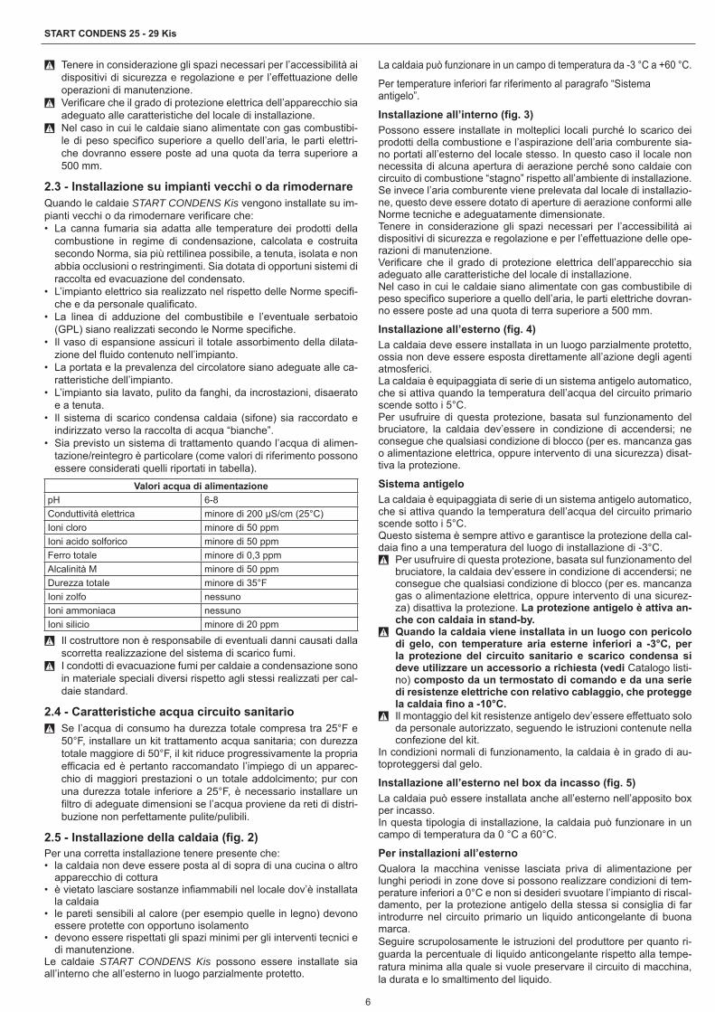
2.4 - Caratteristiche acqua circuito sanitario 9 Se l’acqua di consumo ha durezza totale compresa tra 25°F e
50°F, installare un kit trattamento acqua sanitaria; con durezza totale maggiore di 50°F, il kit riduce progressivamente la propria efficacia ed è pertanto raccomandato l’impiego di un apparec-chio di maggiori prestazioni o un totale addolcimento; pur con una durezza totale inferiore a 25°F, è necessario installare un filtro di adeguate dimensioni se l’acqua proviene da reti di distri-buzione non perfettamente pulite/pulibili.
2.5 - Installazione della caldaia (fig. 2)Per una corretta installazione tenere presente che:• la caldaia non deve essere posta al di sopra di una cucina o altro
apparecchio di cottura• è vietato lasciare sostanze infiammabili nel locale dov’è installata
la caldaia• le pareti sensibili al calore (per esempio quelle in legno) devono
essere protette con opportuno isolamento• devono essere rispettati gli spazi minimi per gli interventi tecnici e
di manutenzione.Le caldaie START CONDENS Kis possono essere installate sia all’interno che all’esterno in luogo parzialmente protetto.
La caldaia può funzionare in un campo di temperatura da -3 °C a +60 °C.
Per temperature inferiori far riferimento al paragrafo “Sistema antigelo”.
Installazione all’interno (fig. 3)Possono essere installate in molteplici locali purché lo scarico dei prodotti della combustione e l’aspirazione dell’aria comburente sia-no portati all’esterno del locale stesso. In questo caso il locale non necessita di alcuna apertura di aerazione perché sono caldaie con circuito di combustione “stagno” rispetto all’ambiente di installazione.Se invece l’aria comburente viene prelevata dal locale di installazio-ne, questo deve essere dotato di aperture di aerazione conformi alle Norme tecniche e adeguatamente dimensionate.Tenere in considerazione gli spazi necessari per l’accessibilità ai dispositivi di sicurezza e regolazione e per l’effettuazione delle ope-razioni di manutenzione.Verificare che il grado di protezione elettrica dell’apparecchio sia adeguato alle caratteristiche del locale di installazione.Nel caso in cui le caldaie siano alimentate con gas combustibile di peso specifico superiore a quello dell’aria, le parti elettriche dovran-no essere poste ad una quota di terra superiore a 500 mm.
Installazione all’esterno (fig. 4)La caldaia deve essere installata in un luogo parzialmente protetto, ossia non deve essere esposta direttamente all’azione degli agenti atmosferici.La caldaia è equipaggiata di serie di un sistema antigelo automatico, che si attiva quando la temperatura dell’acqua del circuito primario scende sotto i 5°C.Per usufruire di questa protezione, basata sul funzionamento del bruciatore, la caldaia dev’essere in condizione di accendersi; ne consegue che qualsiasi condizione di blocco (per es. mancanza gas o alimentazione elettrica, oppure intervento di una sicurezza) disat-tiva la protezione.
Sistema antigeloLa caldaia è equipaggiata di serie di un sistema antigelo automatico, che si attiva quando la temperatura dell’acqua del circuito primario scende sotto i 5°C.Questo sistema è sempre attivo e garantisce la protezione della cal-daia fino a una temperatura del luogo di installazione di -3°C.
9 Per usufruire di questa protezione, basata sul funzionamento del bruciatore, la caldaia dev’essere in condizione di accendersi; ne consegue che qualsiasi condizione di blocco (per es. mancanza gas o alimentazione elettrica, oppure intervento di una sicurez-za) disattiva la protezione. La protezione antigelo è attiva an-che con caldaia in stand-by.
9 Quando la caldaia viene installata in un luogo con pericolo di gelo, con temperature aria esterne inferiori a -3°C, per la protezione del circuito sanitario e scarico condensa si deve utilizzare un accessorio a richiesta (vedi Catalogo listi-no) composto da un termostato di comando e da una serie di resistenze elettriche con relativo cablaggio, che protegge la caldaia fino a -10°C.
9 Il montaggio del kit resistenze antigelo dev’essere effettuato solo da personale autorizzato, seguendo le istruzioni contenute nella confezione del kit.
In condizioni normali di funzionamento, la caldaia è in grado di au-toproteggersi dal gelo.
Installazione all’esterno nel box da incasso (fig. 5)La caldaia può essere installata anche all’esterno nell’apposito box per incasso.In questa tipologia di installazione, la caldaia può funzionare in un campo di temperatura da 0 °C a 60°C.
Per installazioni all’esternoQualora la macchina venisse lasciata priva di alimentazione per lunghi periodi in zone dove si possono realizzare condizioni di tem-perature inferiori a 0°C e non si desideri svuotare l’impianto di riscal-damento, per la protezione antigelo della stessa si consiglia di far introdurre nel circuito primario un liquido anticongelante di buona marca.Seguire scrupolosamente le istruzioni del produttore per quanto ri-guarda la percentuale di liquido anticongelante rispetto alla tempe-ratura minima alla quale si vuole preservare il circuito di macchina, la durata e lo smaltimento del liquido.

7
ITALIANO
Per la parte sanitaria, si consiglia di svuotare il circuito.I materiali con cui sono realizzati i componenti delle caldaie resisto-no a liquidi congelanti a base di glicoli etilenici.Sono disponibili kit antigelo dedicati ad installazioni all’esterno.
Dima di premontaggioLa caldaia è fornita di dima di premontaggio che permette di realiz-zare i collegamenti all’impianto termico e sanitario senza l’ingombro della caldaia, che potrà essere montata successivamente.Collegare ad un adeguato sistema di scarico il collettore scarichi.Le caldaie START CONDENS Kis sono progettate e realizzate per essere installate su impianti di riscaldamento e di produzione di ac-qua calda sanitaria.La posizione e la dimensione degli attacchi idraulici sono riportate nelle illustrazioni.• Posizionare la dima in cartone a muro, con l’aiuto di una livella a
bolla: controllare il corretto piano orizzontale e la planarità della superficie di appoggio della caldaia; nel caso fosse necessario prevedere uno spessoramento
• Tracciare i punti di fissaggio• Togliere la dima ed eseguire la foratura• Controllare con una livella a bolla la corretta orizzontalità.
Fissaggio della caldaiaAgganciare la caldaia (fig. 6).
Collegamenti idraulici
86,5
140
65 50 80 65
M AC G R AF
58,5
M Mandata riscaldamentoAC Uscita acqua caldaG GasR Ritorno riscaldamentoAF Entrata acqua freddaSC Scarico condensa
Si consiglia di collegare la caldaia agli impianti inserendo oltre al rubinetto di intercettazione dell’acqua sanitaria anche i rubinetti di intercettazione per l’impianto di riscaldamento; a tale proposito è disponibile il kit rubinetti impianto di riscaldamento e il kit rubinetti riscaldamento con filtro.
9 La scelta e l’installazione dei componenti dell’impianto sono de-mandate all’installatore, che dovrà operare secondo le regole della buona tecnica e della Legislazione vigente.
Raccolta condensa (fig. 7)L’impianto deve essere realizzato in modo da evitare il congelamen-to della condensa prodotta dalla caldaia (per es. coibentandolo). Si consiglia l’installazione di un apposito collettore di scarico in mate-riale polipropilene reperibile in commercio sulla parte inferiore della caldaia - foro Ø 42- come indicato in figura.Posizionare il tubo flessibile di scarico condensa fornito con la cal-daia, collegandolo al collettore (o altro dispositivo di raccordo ispe-zionabile) evitando di creare pieghe dove la condensa possa rista-gnare ed eventualmente congelare.Il costruttore non è responsabile per eventuali danni causati dalla mancanza di convogliamento della condensa o da congelamento della stessa.La linea di collegamento dello scarico deve essere a tenuta garanti-ta e adeguatamente protetta dai rischi di gelo.
Prima della messa in servizio dell’apparecchio assicurarsi che la condensa possa essere evacuata correttamente.
2.6 - Installazione della sonda esterna (accessorio)Il corretto funzionamento della sonda esterna è fondamentale per il buon funzionamento del controllo climatico.
Installazione e allacciamento della sonda esternaLa sonda deve essere installata su una parete esterna all’edificio che si vuole riscaldare avendo l’accortezza di rispettare le seguenti indicazioni:• Deve essere montata sulla facciata più frequentemente esposta
al vento, parete posta a NORD o NORD-OVEST evitando l’irrag-giamento diretto dei raggi solari;
• Deve essere montata a circa 2/3 dell’altezza della facciata;• Non deve trovarsi in prossimità di porte, finestre, scarichi di con-
dotto d’aria o a ridosso di canne fumarie o altre fonti di calore.Il collegamento elettrico alla sonda esterna va effettuato con un cavo bipolare con sezione da 0.5 a 1 mm2, non fornito a corredo, con lunghezza massima di 30 metri. Non è necessario rispettare la polarità del cavo da allacciare alla sonda esterna. Evitare di effet-tuare giunte su questo cavo; nel caso fossero necessarie devono essere stagnate ed adeguatamente protette.Eventuali canalizzazioni del cavo di collegamento devono essere separate da cavi in tensione (230V a.c.).
Fissaggio al muro della sonda esterna (fig. 8)La sonda va posta in un tratto di muro liscio; in caso di mattoni a vi-sta o parete irregolare va prevista un’area di contatto possibilmente liscia.• Svitare il coperchio di protezione superiore in plastica ruotandolo
in senso antiorario.• Identificare il luogo di fissaggio al muro ed eseguire la foratura per
il tassello ad espansione da 5x25.• Inserire il tassello nel foro.• Sfilare la scheda dalla propria sede.• Fissare la scatola al muro utilizzando la vite fornita a corredo.• Agganciare la staffa e serrare la vite.• Svitare il dado del passacavo, introdurre il cavo di collegamento
della sonda e collegarlo al morsetto elettrico.Per il collegamento elettrico della sonda esterna alla caldaia, fare riferimento al capitolo “Collegamenti elettrici”.
9 Ricordarsi di chiudere bene il passacavo per evitare che l’umidi-tà dell’aria entri attraverso l’apertura dello stesso.
• Infilare nuovamente la scheda nella sede.• Chiudere il coperchio di protezione superiore in plastica ruotando-
lo in senso orario. Serrare molto bene il passacavo.
2.7 - Collegamenti elettriciLe caldaie START CONDENS Kis lasciano la fabbrica completa-mente cablate e necessitano solamente del collegamento alla rete di alimentazione elettrica (utilizzando il cavo di alimentazione in do-tazione) e del termostato ambiente (TA) e/o programmatore orario, da effettuarsi ai morsetti dedicati.• Posizionare l’interruttore generale dell’impianto su “spento”.• Svitare le viti (A - fig. 9) di fissaggio del mantello.• Spostare in avanti e poi verso l’alto la base del mantello per sgan-
ciarlo dal telaio.• Svitare la vite di fissaggio (B - fig. 10) del cruscotto.• Ruotare il cruscotto in avanti.• Svitare le viti di fissaggio (C - fig. 11) per accedere alla morset-
tiera. 9 Ingresso termostato ambiente in bassa tensione di sicurezza
(contatto pulito). 9 In caso di alimentazione fase-fase verificare con un tester quale
dei due fili ha potenziale maggiore rispetto alla terra e collegarlo alla L, in egual maniera collegare il filo rimanente alla N.
9 La caldaia può funzionare con alimentazione fase-neutro o fa-se-fase. Per alimentazioni flottanti, ovvero prive all’origine di ri-ferimento a terra, è necessario l’utilizzo di un trasformatore di isolamento con secondario ancorato a terra.
9 È obbligatorio:
8
START CONDENS 25 - 29 Kis
• l’impiego di un interruttore magnetotermico onnipolare, sezio-natore di linea, conforme alle Norme CEI-EN 60335-1 (apertu-ra dei contatti di almeno 3,5mm, categoria III)
• utilizzare cavi di sezione ≥ 1,5mm2 e rispettare il collegamento L (Fase) - N (Neutro)
• l’amperaggio dell’interruttore deve essere adeguato alla po-tenza elettrica della caldaia, riferirsi ai dati tecnici per verifica-re la potenza elettrica del modello installato
• collegare l’apparecchio ad un efficace impianto di terra• salvaguardare l’accessibilità alla presa di corrente dopo l’in-
stallazione 0 È vietato l’uso dei tubi del gas e dell’acqua per la messa a terra
dell’apparecchio. 9 Il costruttore non è responsabile di eventuali danni causati dall’i-
nosservanza di quanto riportato negli schemi elettrici. 9 È responsabilità dell’installatore assicurare un’adeguata messa
a terra dell’apparecchio; il costruttore non risponde per eventuali danni causati da una non corretta o mancata realizzazione della stessa.
2.8 - Configurazione caldaiaSulla scheda elettronica è disponibile una serie di ponticelli (JPX) che permettono di configurare la caldaia.Per accedere alla scheda operare come segue:• Posizionare l’interruttore generale dell’impianto su spento.• Svitare le viti (A - fig. 9) di fissaggio del mantello.• Spostare in avanti e poi verso l’alto la base del mantello per sgan-
ciarlo dal telaio.• Svitare la vite di fissaggio (B - fig. 10) del cruscotto.• Ruotarle il cruscotto in avanti.• Svitare le viti di fissaggio (C - fig. 11) per accedere alla morset-
tiera.
Jumper JP7 (fig. 12)Preselezione del campo di regolazione della temperatura riscalda-mento più idonea secondo al tipo di impianto.• Jumper non inserito: impianto standard (40-80°C).• Jumper inserito: impianto a pavimento (20-45°C).In fase di fabbricazione la caldaia è stata configurata per impianti standard.
Jumper DescrizioneJP1 Taratura (Range Rated)JP2 Azzeramento timer riscaldamentoJP3 Taratura (vedi paragrafo “Regolazioni”)JP4 Selettore termostati sanitario assolutiJP5 Non utilizzareJP6 Abilitazione funzione compensazione notturna e pompa
in continuo (solo con sonda esterna collegata)JP7 Abilitazione gestione impianti standard/bassa
temperatura (vedi sopra)JP8 Non utilizzare
2.9 - Collegamento gasIl collegamento delle caldaie START CONDENS Kis all’alimentazio-ne del gas deve essere eseguito nel rispetto delle Norme di instal-lazione vigenti.Prima di eseguire il collegamento è necessario assicurarsi che:• il tipo di gas sia quello per il quale l’apparecchio è predisposto• le tubazioni siano accuratamente pulite.
9 L’impianto di alimentazione del gas deve essere adeguato alla portata della caldaia e deve essere dotato di tutti i dispositivi di sicurezza e di controllo prescritti dalle Norme vigenti. È consi-gliato l’impiego di un filtro di opportune dimensioni.
9 Ad installazione effettuata verificare che le giunzioni eseguite siano a tenuta.
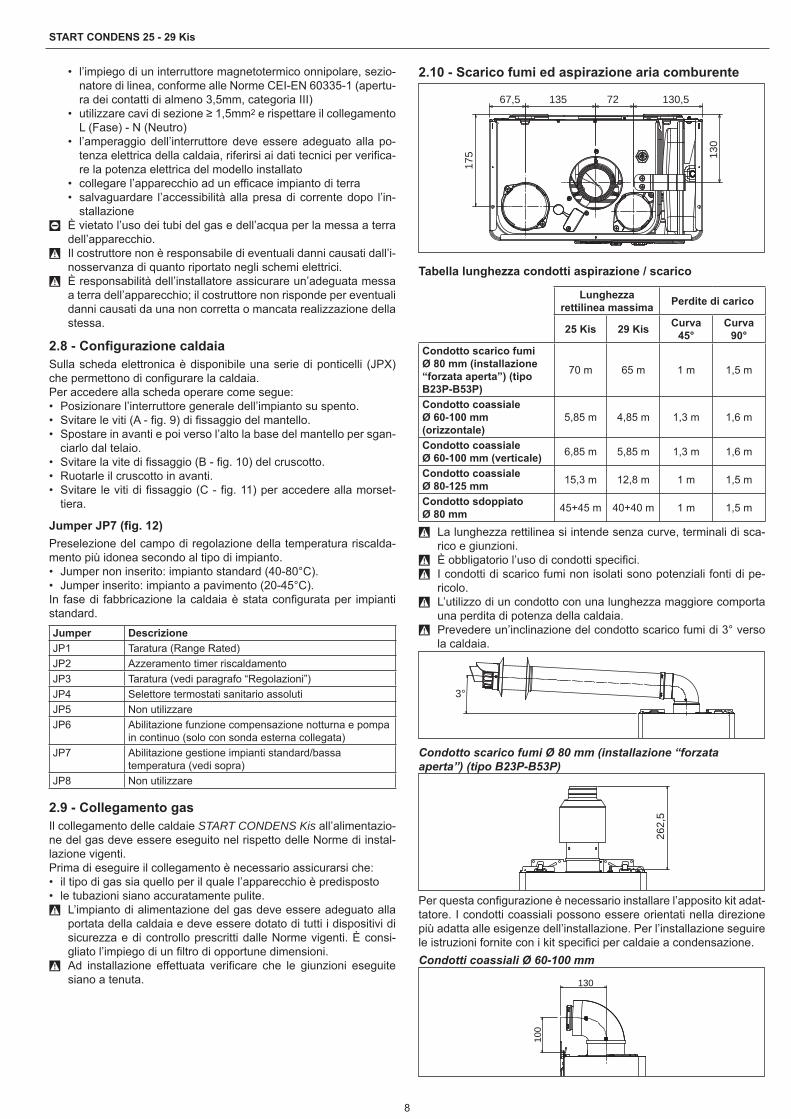
2.10 - Scarico fumi ed aspirazione aria comburente
67,5 135 72 130,5
130
175
Tabella lunghezza condotti aspirazione / scarico
Lunghezza rettilinea massima Perdite di carico
25 Kis 29 Kis Curva 45°
Curva 90°
Condotto scarico fumi Ø 80 mm (installazione “forzata aperta”) (tipo B23P-B53P)
70 m 65 m 1 m 1,5 m
Condotto coassiale Ø 60-100 mm (orizzontale)
5,85 m 4,85 m 1,3 m 1,6 m
Condotto coassiale Ø 60-100 mm (verticale) 6,85 m 5,85 m 1,3 m 1,6 m
Condotto coassiale Ø 80-125 mm 15,3 m 12,8 m 1 m 1,5 m
Condotto sdoppiato Ø 80 mm 45+45 m 40+40 m 1 m 1,5 m
9 La lunghezza rettilinea si intende senza curve, terminali di sca-rico e giunzioni.
9 È obbligatorio l’uso di condotti specifici. 9 I condotti di scarico fumi non isolati sono potenziali fonti di pe-
ricolo. 9 L’utilizzo di un condotto con una lunghezza maggiore comporta
una perdita di potenza della caldaia. 9 Prevedere un’inclinazione del condotto scarico fumi di 3° verso
la caldaia.
3°
Condotto scarico fumi Ø 80 mm (installazione “forzata aperta”) (tipo B23P-B53P)
262,
5
Per questa configurazione è necessario installare l’apposito kit adat-tatore. I condotti coassiali possono essere orientati nella direzione più adatta alle esigenze dell’installazione. Per l’installazione seguire le istruzioni fornite con i kit specifici per caldaie a condensazione.Condotti coassiali Ø 60-100 mm
130
100

9
ITALIANO
Condotti sdoppiati Ø 80 mm
134
134
87 129
Kit adattatore ingresso aria
Ø 80 mm
Kit adattatore ingresso aria da
Ø 60 mm a Ø 80 mm
Lunghezza massima tubi Ø 80 mm - 25 KIS
0
10
20
30
40
50
60
70
80
0 5 10 15 20 25 30 35 40 45 50 55 60 65 70 75 80 85 90 95 100 105 110
Lunghezza condotto aspirazione (m)
Lung
hezz
a co
ndot
to s
caric
o (m
)
Lunghezza massima tubi Ø 80 mm - 29 KIS
0
10
20
30
40
50
60
70
0 5 10 15 20 25 30 35 40 45 50 55 60 65 70 75 80 85 90 95
Lunghezza condotto aspirazione (m)
Lung
hezz
a co
ndot
to s
caric
o (m
)
Scarico posteriore
Qualora si rendesse necessario installare la caldaia con scarico po-steriore, utilizzare la curva specifica (kit fornibile a richiesta).
In questo tipo di installazione è necessario tagliare il tubo interno della curva nel punto indicato in figura per consentire un inserimento più agevole della curva stessa nello scarico fumi della caldaia.
2.11 - Caricamento e svuotamento impiantiEffettuati i collegamenti idraulici, si può procedere al caricamento dell’impianto.
Caricamento• Aprire di due o tre giri i tappi delle valvole di sfogo aria automatica
inferiore (A - fig. 13) e superiore (D - fig. 13); per permettere un continuo sfiato dell’aria, lasciare aperti i tappi delle valvole A e D. (fig. 13).
• Accertarsi che il rubinetto entrata acqua fredda sia aperto ruotan-dolo in senso antiorario.
• Aprire il rubinetto di riempimento (B - fig. 13) fino a che la pressio-ne indicata dall’idrometro sia compresa tra 1 bar e 1,5 bar.
• Richiudere il rubinetto di riempimento (B - fig. 13).NOTA - La disaerazione della caldaia START CONDENS Kis avvie-ne automaticamente attraverso le due valvole di sfiato automatico A e D (fig. 13), la prima posizionata sul circolatore mentre la seconda all’interno della cassa aria.NOTA - Nel caso in cui la fase di disaerazione risultasse difficoltosa, operare come descritto nel paragrafo “Eliminazione dell’aria dal cir-cuito riscaldamento e dalla caldaia”.
Svuotamento• Prima di iniziare lo svuotamento togliere l’alimentazione elettrica
posizionando l’interruttore generale dell’impianto su “spento”• Chiudere il rubinetto entrata acqua freddaImpianto di riscaldamento• Chiudere i dispositivi di intercettazione dell’impianto termico• Allentare manualmente la valvola di scarico impianto (C - fig. 13)• L’acqua dell’impianto viene scaricata attraverso il collettore scari-
chi - per dettagli riferirsi al paragrafo collettore scarichi.Impianto sanitario• Aprire i rubinetti dell’utenza acqua calda e fredda e svuotare i pun-
ti più bassi.
Eliminazione dell’aria dal circuito riscaldamento e dalla caldaia (fig. 14)Durante la fase di prima installazione o in caso di manutenzione straordinaria, si raccomanda di attuare la seguente sequenza di operazioni:• Con una chiave CH11 aprire la valvola di sfogo aria manuale po-
sizionata sopra la cassa aria: è necessario collegare alla valvola il tubetto a corredo caldaia per poter scaricare l’acqua in un reci-piente esterno.
• Aprire il rubinetto di riempimento impianto manuale sul gruppo idraulico, attendere sino a quando inizia a fuoriuscire acqua dalla valvola.
• Alimentare elettricamente la caldaia lasciando chiuso il rubinetto del gas.
• Attivare una richiesta di calore tramite il termostato ambiente o il pannello di comando remoto in modo che la tre-vie si posizioni in riscaldamento.
• Attivare una richiesta sanitaria aprendo un rubinetto (solo nel caso di caldaie istantanee, per le caldaia solo riscaldamento col-legate ad un bollitore esterno agire sul termostato del bollitore) per la durata di 30” ogni minuto per far si che la tre-vie cicli da riscaldamento a sanitario e viceversa per una decina di volte (in questa situazione la caldaia andrà in allarme per mancanza gas, quindi resettarla ogni qualvolta questo si riproponga).
• Continuare la sequenza sino a che dall’uscita della valvola sfogo aria manuale fuoriesca unicamente acqua e che il flusso dell’aria si sia terminato; a questo punto chiudere la valvola di sfogo aria manuale.
• Verificare la corretta pressione presente nell’impianto (ideale 1 bar).
• Chiudere il rubinetto di riempimento impianto manuale sul gruppo idraulico.
• Aprire il rubinetto del gas ed effettuare l’accensione della caldaia.

10
START CONDENS 25 - 29 Kis
2.12 - Preparazione alla prima messa in servizioPrima di effettuare l’accensione e il collaudo funzionale della caldaia START CONDENS Kis è indispensabile:• controllare che i rubinetti del combustibile e dell’acqua di alimen-
tazione degli impianti siano aperti (fig. 15)• controllare che il tipo di gas e la pressione di alimentazione siano
quelli per i quali la caldaia è predisposta• verificare che il cappuccio della valvola di sfiato sia aperto• controllare che la pressione del circuito idraulico, a freddo, visua-
lizzata sul display, sia compresa tra 1 bar e 1,5 bar ed il circuito sia disaerato
• controllare che la precarica del vaso di espansione sia adeguata (riferirsi alla tabella dati tecnici)
• controllare che gli allacciamenti elettrici siano stati eseguiti cor-rettamente
• controllare che i condotti di scarico dei prodotti della combustione, di aspirazione dell’aria comburente siano stati realizzati adegua-tamente
• controllare che il circolatore ruoti liberamente in quanto, soprattut-to dopo lunghi periodi di non funzionamento, depositi e/o residui possono impedire la libera rotazione. 9 Prima di allentare o rimuovere il tappo di chiusura del circolato-
re proteggere i dispositivi elettrici sottostanti dall’eventuale fuori uscita d’acqua.
2.13 - Controllo prima della messa in servizio 9 Alla prima accensione della caldaia il sifone per la raccolta della
condensa è vuoto. È quindi indispensabile creare un battente d’acqua riempiendo il sifone prima della messa in servizio in base alle seguenti istruzioni:• rimuovere il sifone sganciandolo dal tubo in plastica di collega-
mento alla camera di combustione• riempire il sifone per circa 3/4” con acqua, verificando che sia
libero da impurità• verificare il galleggiamento del cilindro in plastica• riposizionare il sifone, facendo attenzione a non svuotarlo, e
fissarlo con la molletta.La presenza del cilindro in plastica all’interno del sifone ha lo scopo di evitare la fuoriuscita di gas combusti in ambiente nel caso l’ap-parecchio venisse messo in servizio senza prima creare il battente d’acqua nel sifone. Ripetere questa operazione durante gli interventi di manutenzione ordinaria e straordinaria.• Regolare il termostato ambiente alla temperatura desiderata
(~20°C) oppure se l’impianto è dotato di cronotermostato o pro-grammatore orario che sia “attivo” e regolato (~20°C)
• Ad ogni alimentazione elettrica compaiono sul display una serie di informazioni tra cui il valore del contatore sonda fumi (-C- XX - vedi paragrafo “Display e codici anomalie” - anomalia A 09), suc-cessivamente la caldaia inizia un ciclo automatico di sfiato della durata di circa 2 minuti
• Sul display viene visualizzato il simbolo .
Per interrompere il ciclo di sfiato automatico agire come segue:• Accedere alla scheda elettronica rimuovendo il mantello, ruotando
il cruscotto verso sé e aprendo la copertura morsettiera (fig. 16)Successivamente:• Utilizzando il cacciavite fornito a corredo, premere il pulsante CO
(fig. 16).• Parti elettriche in tensione (230 Vac).Per l’accensione della caldaia è necessario, effettuare le seguenti operazioni:• Alimentare elettricamente la caldaia• Aprire il rubinetto del gas, per permettere il flusso del combustibile• Regolare il termostato ambiente alla temperatura desiderata
(~20°C)• Ruotare il selettore di funzione nella posizione desiderata.
2.14 - Controlli durante e dopo la prima messa in servizioA seguito della messa in servizio, verificare che la caldaia START CONDENS Kis esegua correttamente le procedure di avvia-mento e successivo spegnimento agendo su:• Selettore di funzione• Taratura del selettore temperatura acqua riscaldamento e del se-
lettore temperatura acqua sanitario• Temperatura richiesta in ambiente (intervenendo sul termostato
ambiente o sul programmatore orario)Verificare il funzionamento in sanitario aprendo un rubinetto dell’ac-qua calda con il selettore di funzione sia in modo estate che in modo inverno che in modo inverno con preriscaldo.Verificare l’arresto totale della caldaia posizionando l’interruttore ge-nerale dell’impianto su “spento”.Dopo qualche minuto di funzionamento continuo da ottenersi posi-zionando l’interruttore generale dell’impianto su “acceso”, il selettore di funzione su estate e mantenendo aperta l’utenza sanitaria, i le-ganti e i residui di lavorazione evaporano e sarà possibile effettuare:• Il controllo della pressione del gas di alimentazione• Il controllo della combustione.
Controllo della pressione del gas di alimentazione• Portare il selettore di funzione su per spegnere la caldaia
• Svitare le viti (A - fig. 9) di fissaggio del mantello• Spostare in avanti e poi verso l’alto la base del mantello per sgan-
ciarlo dal telaio• Svitare la vite di fissaggio (B - fig. 10) del cruscotto• Ruotare il cruscotto in avanti• Svitare di circa due giri la vite della presa di pressione a monte
della valvola gas (C - fig. 17) e collegarvi il manometro• Alimentare elettricamente la caldaia posizionando l’interruttore
generale dell’impianto su “acceso”• Portare il selettore di funzione su estate• Ruotare il selettore di temperatura acqua sanitaria al massimo• Aprire un rubinetto dell’acqua calda alla massima portata• Verificare a bruciatore acceso alla massima potenza che la pres-
sione del gas sia compresa tra i valori di pressione minima e no-minale di alimentazione indicati nella tabella multigas
• Chiudere il rubinetto dell’acqua calda• Scollegare il manometro e riavvitare la vite della presa di pressio-
ne a monte della valvola gas.
Controllo della combustionePer effettuare l’analisi della combustione eseguire le seguenti ope-razioni:• Posizionare l’interruttore generale dell’impianto su spento• Svitare le viti (A - fig. 9) di fissaggio del mantello• Spostare in avanti e poi verso l’alto la base del mantello per sgan-
ciarlo dal telaio• Svitare la vite (B - fig. 10) di fissaggio del cruscotto• Ruotare il cruscotto verso di sé• Svitare le viti di fissaggio (C - fig. 11) per accedere alla morsettiera• Utilizzando il cacciavite fornito a corredo, premere una volta il pul-
sante “CO” (fig. 16) 9 Parti elettriche in tensione (230 Vac).
• Attendere l’accensione del bruciatore. Il display visualizza “ACO”, la caldaia funziona alla massima potenza riscaldamento
• Rimuovere la vite e il coperchietto sulla cassa aria• Inserire l’adattatore sonda analisi presente nella busta documen-
tazione nel foro preposto all’analisi combustione• Inserire la sonda analisi fumi all’interno dell’adattatore• Verificare che i valori di CO2 corrispondano a quelli indicati nella
tabella multigas, se il valore visualizzato è differente procedere alla modifica come indicato nel capitolo “Taratura valvola gas”.
• Effettuare il controllo della combustione.
11
ITALIANO
Successivamente:• Rimuovere le sonde dell’analizzatore e chiudere le prese per l’a-
nalisi combustione con l’apposita vite• Chiudere il cruscotto e riposizionare il mantello
9 La sonda per l’analisi dei fumi deve essere inserita fino ad arri-vare in battuta.
9 Anche durante la fase di analisi combustione rimane inserita la funzione che spegne la caldaia quando la temperatura dell’ac-qua raggiunge il limite massimo di circa 90 °C.
A controlli terminati:• Posizionare il selettore di funzione a seconda del tipo di funziona-
mento desiderato• Regolare i selettori (2 e 3) secondo le esigenze del cliente.
9 Le caldaie START CONDENS Kis vengono fornite per il funzio-namento a gas metano (G20) e sono già regolate in fabbrica secondo quanto indicato nella targhetta tecnica, quindi non ne-cessitano di alcuna operazione di taratura.
9 Tutti i controlli devono essere eseguiti esclusivamente dal Servi-zio Tecnico di Assistenza.
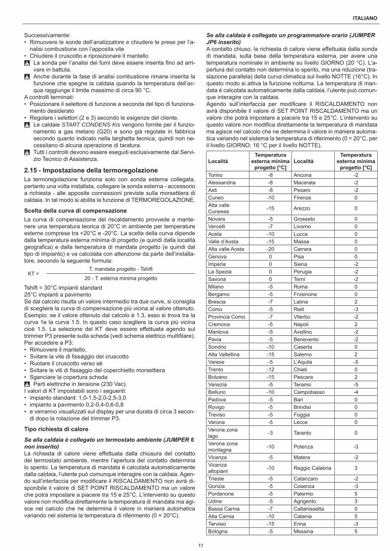
2.15 - Impostazione della termoregolazioneLa termoregolazione funziona solo con sonda esterna collegata, pertanto una volta installata, collegare la sonda esterna - accessorio a richiesta - alle apposite connessioni previste sulla morsettiera di caldaia. In tal modo si abilita la funzione di TERMOREGOLAZIONE.
Scelta della curva di compensazioneLa curva di compensazione del riscaldamento provvede a mante-nere una temperatura teorica di 20°C in ambiente per temperature esterne comprese tra +20°C e -20°C. La scelta della curva dipende dalla temperatura esterna minima di progetto (e quindi dalla località geografica) e dalla temperatura di mandata progetto (e quindi dal tipo di impianto) e va calcolata con attenzione da parte dell’installa-tore, secondo la seguente formula:
KT =T. mandata progetto - Tshift
20 - T. esterna minima progetto
Tshift = 30°C impianti standard25°C impianti a pavimentoSe dal calcolo risulta un valore intermedio tra due curve, si consiglia di scegliere la curva di compensazione più vicina al valore ottenuto.Esempio: se il valore ottenuto dal calcolo è 1.3, esso si trova tra la curva 1e la curva 1.5. In questo caso scegliere la curva più vicina cioè 1.5. La selezione del KT deve essere effettuata agendo sul trimmer P3 presente sulla scheda (vedi schema elettrico multifilare).Per accedere a P3:• Rimuovere il mantello,• Svitare la vite di fissaggio del cruscotto• Ruotare il cruscotto verso sé• Svitare le viti di fissaggio del coperchietto morsettiera• Sganciare la copertura scheda
9 Parti elettriche in tensione (230 Vac).I valori di KT impostabili sono i seguenti:• impianto standard: 1,0-1,5-2,0-2,5-3,0• impianto a pavimento 0,2-0,4-0,6-0,8• e verranno visualizzati sul display per una durata di circa 3 secon-
di dopo la rotazione del trimmer P3.
Tipo richiesta di calore
Se alla caldaia è collegato un termostato ambiente (JUMPER 6 non inserito)La richiesta di calore viene effettuata dalla chiusura del contatto del termostato ambiente, mentre l’apertura del contatto determina lo spento. La temperatura di mandata è calcolata automaticamente dalla caldaia, l’utente può comunque interagire con la caldaia. Agen-do sull’interfaccia per modificare il RISCALDAMENTO non avrà di-sponibile il valore di SET POINT RISCALDAMENTO ma un valore che potrà impostare a piacere tra 15 e 25°C. L’intervento su questo valore non modifica direttamente la temperatura di mandata ma agi-sce nel calcolo che ne determina il valore in maniera automatica variando nel sistema la temperatura di riferimento (0 = 20°C).
Se alla caldaia è collegato un programmatore orario (JUMPER JP6 inserito)A contatto chiuso, la richiesta di calore viene effettuata dalla sonda di mandata, sulla base della temperatura esterna, per avere una temperatura nominale in ambiente su livello GIORNO (20 °C). L’a-pertura del contatto non determina lo spento, ma una riduzione (tra-slazione parallela) della curva climatica sul livello NOTTE (16°C). In questo modo si attiva la funzione notturna. La temperatura di man-data è calcolata automaticamente dalla caldaia, l’utente può comun-que interagire con la caldaia.Agendo sull’interfaccia per modificare il RISCALDAMENTO non avrà disponibile il valore di SET POINT RISCALDAMENTO ma un valore che potrà impostare a piacere tra 15 e 25°C. L’intervento su questo valore non modifica direttamente la temperatura di mandata ma agisce nel calcolo che ne determina il valore in maniera automa-tica variando nel sistema la temperatura di riferimento (0 = 20°C, per il livello GIORNO; 16 °C per il livello NOTTE).
LocalitàTemperatura
esterna minima progetto [°C]
LocalitàTemperatura
esterna minima progetto [°C]
Torino -8 Ancona -2Alessandria -8 Macerata -2Asti -8 Pesaro -2Cuneo -10 Firenze 0Alta valle Cuneese -15 Arezzo 0
Novara -5 Grosseto 0Vercelli -7 Livorno 0Aosta -10 Lucca 0Valle d’Aosta -15 Massa 0Alta valle Aosta -20 Carrara 0Genova 0 Pisa 0Imperia 0 Siena -2La Spezia 0 Perugia -2Savona 0 Terni -2Milano -5 Roma 0Bergamo -5 Frosinone 0Brescia -7 Latina 2Como -5 Rieti -3Provincia Como -7 Viterbo -2Cremona -5 Napoli 2Mantova -5 Avellino -2Pavia -5 Benevento -2Sondrio -10 Caserta 0Alta Valtellina -15 Salerno 2Varese -5 L’Aquila -5Trento -12 Chieti 0Bolzano -15 Pescara 2Venezia -5 Teramo -5Belluno -10 Campobasso -4Padova -5 Bari 0Rovigo -5 Brindisi 0Treviso -5 Foggia 0Verona -5 Lecce 0Verona zona lago -3 Taranto 0
Verona zona montagna -10 Potenza -3
Vicenza -5 Matera -2Vicenza altopiani -10 Reggio Calabria 3
Trieste -5 Catanzaro -2Gorizia -5 Cosenza -3Pordenone -5 Palermo 5Udine -5 Agrigento 3Bassa Carnia -7 Caltanissetta 0Alta Carnia -10 Catania 5Tarvisio -15 Enna -3Bologna -5 Messina 5

12
START CONDENS 25 - 29 Kis
LocalitàTemperatura
esterna minima progetto [°C]
LocalitàTemperatura
esterna minima progetto [°C]
Ferrara -5 Ragusa 0Forlì -5 Siracusa 5Modena -5 Trapani 5Parma -5 Cagliari 3Piacenza -5 Nuoro 0Provincia Piacenza -7 Sassari 2
Reggio Emilia -5
Resta salvo il fatto che in base alla sua esperienza l’installatore può scegliere curve diverse.
Curve di termoregolazioneIl display visualizza il valore della curva moltiplicato per 10 (es. 3,0 = 30)
Temperatura esterna (˚C)
Tem
pera
tura
di
man
data
(˚C
)
20
30
40
50
60
70
80
90
100
-20
0,2
0,4
0,6
0,8
1,0
1,5
2,02,53,0
T80
T45
-15-10-505101520
Temperatura esterna (°C)
Tem
pera
tura
di m
anda
ta (°
C)
T80 - Massima temperatura set point riscaldamento impianti standard (jumper pos. 1 non inserito).T45 - Massima temperatura set point riscaldamento impianti a pavimento (jumper pos. 1 inserito).
Correzione curva climatica
20 °C25 ° C
15 °C
10
20
30
40
50
60
70
80
90
-20-15-10-5051015202530
Temperatura esterna (°C)
Tem
pera
tura
di m
anda
ta (°
C)
Riduzione notturna parallela
10
20
30
40
50
60
70
80
90
-20-15-10-505101520Temperatura Esterna
Tem
per
atu
ra d
i
Curva climatica GIORNO
Curva climatica NOTTE
16 °C20 °C
Temperatura esterna (°C)
Curva climatica notte
Curva climatica giorno
Tem
pera
tura
di m
anda
ta (°
C)
3 - RegolazioniLe caldaie START CONDENS Kis vengono fornite per il funziona-mento a gas metano (G20) e sono state regolate in fabbrica secon-do quanto indicato nella targhetta tecnica.Se fosse però necessario effettuare nuovamente le regolazioni, ad esempio dopo una manutenzione straordinaria, la sostituzione della valvola del gas oppure dopo una trasformazione da gas metano a GPL o viceversa, bisogna seguire le procedure descritte di seguito.
9 Le regolazioni della massima e minima potenza, del massimo riscaldamento e della lenta accensione devono essere eseguite tassativamente nella sequenza indicata ed esclusivamente da personale qualificato.
• Togliere alimentazione alla caldaia• Portare il selettore temperatura acqua riscaldamento al valore
massimo• Svitare le viti di fissaggio dello sportellino posto sulla copertura
morsettiera• Inserire i jumper JP1 e JP3• Alimentare la caldaia• Il display visualizza “ADJ” per circa 4secProcedere alla modifica dei seguenti parametri:• Massimo assoluto/sanitario• Minimo• Massimo riscaldamento• Lenta accensioneCome di seguito descritto:• Ruotare il selettore temperatura acqua riscaldamento per impo-
stare il valore desiderato• Utilizzando il cacciavite fornito a corredo, premere il pulsante CO
(A - fig. 16) e passare alla taratura del parametro successivo. 9 Parti elettriche in tensione (230 Vac).
Sul visualizzatore si accenderanno le seguenti icone:• durante la taratura di massimo assoluto/sanitario• durante la taratura di minimo• durante la taratura di massimo riscaldamento• durante la taratura di lenta accensioneTerminare la procedura rimuovendo i jumper JP1 e JP3 per memo-rizzare i valori cosi impostati.È possibile terminare la funzione in qualsiasi momento senza me-morizzare i valori impostati mantenendo quelli iniziali:• Rimuovendo i jumper JP1 e JP3 prima che siano stati impostati
tutti e 4 i parametri• Portando il selettore di funzione su OFF/RESET• Togliendo la tensione di rete dopo 15 minuti dalla sua attivazione.
9 La taratura non comporta l’accensione della caldaia. 9 Con la rotazione della manopola di selezione riscaldamento vie-
ne visualizzato in automatico sul visualizzatore il numero di giri espresso in centinaia (es. 25 = 2500 g/min).
La funzione di visualizzazione dei parametri di taratura viene attivata con selettore di funzione in estate o inverno premendo il pulsante CO (A - fig. 16) presente sulla scheda indipendentemente dalla pre-senza o assenza di richiesta di calore. Non è possibile attivare la funzione se è collegato un comando remoto.Attivando la funzione i parametri di taratura vengono visualizzati nell’ordine indicato sotto, ciascuno per un tempo pari a 2 secondi. In corrispondenza di ciascun parametro si visualizza la relativa icona e il valore di giri ventilatore espresso in centinaia• Massimo • Minimo • Massimo riscaldamento • Lenta accensione • Massimo riscaldamento regolato
3.1 - Taratura valvola gas• Alimentare elettricamente la caldaia• Aprire il rubinetto del gas• Portare il selettore di funzione su OFF/RESET (visualizzatore
spento)• Rimuovere il mantello e ruotare il cruscotto• Svitare le viti di fissaggio del coperchietto per accedere alla mor-
settiera• Premere una volta il pulsante “CO” (A - fig. 16)

13
ITALIANO
9 Parti elettriche in tensione (230 Vac).• Attendere l’accensione del bruciatore. Il display visualizza “ACO”.
La caldaia funziona alla massima potenza riscaldamento. La fun-zione “analisi combustione” resta attiva per un tempo limite di 15 min,; in caso venga raggiunta una temperatura di mandata di 90°C si ha lo spegnimento del bruciatore. La riaccensione avverrà quando tale temperatura scende al di sotto dei 78°C.
• Rimuovere la vite (A - fig. 18) e il coperchietto (B - fig. 18) sulla cassa aria
• Inserire l’adattatore sonda analisi presente nella busta documen-tazione nel foro preposto all’analisi combustione (C - fig. 18)
• Inserire la sonda analisi fumi all’interno dell’adattatore• Premere il tasto “analisi combustione” una seconda volta per il
raggiungimento del numero di giri corrispondente alla massima potenza sanitaria (consultare la tabella multigas)
• Verificare il valore di CO2: (consultare la tabella multigas) se il valore non risultasse conforme a quanto riportato in tabella agire sulla vite di regolazione del max della valvola gas (A - fig. 19)
• Premere il tasto “analisi combustione” una terza volta per il rag-giungimento del numero di giri corrispondente alla minima poten-za (consultare la tabella multigas).
• Verificare il valore di CO2: (consultare la tabella multigas) se il valore non risultasse conforme a quanto riportato in tabella agire sulla vite di regolazione del min. della valvola gas (B - fig. 19)
• Per uscire dalla funzione “analisi combustione” ruotare la mano-pola di comando
• Estrarre la sonda analisi fumi e rimontare il tappo.• Chiudere il cruscotto e riposizionare il mantello• La funzione “analisi combustione” si disattiva automaticamente se
la scheda genera un allarme. In caso di anomalia durante la fase di analisi combustione, eseguire la procedura di sblocco.
4 - Range ratedQuesta caldaia può essere adeguata al fabbisogno termico dell’im-pianto, è infatti possibile impostare la portata massima per il funzio-namento in riscaldamento della caldaia stessa:• Togliere alimentazione alla caldaia• Portare il selettore temperatura acqua riscaldamento al valore
massimo• Rimuovere il mantello e ruotare il cruscotto (riferirsi ai capitoli pre-
cedenti per il dettaglio delle figure)• Svitare le viti di fissaggio dello sportellino posto sulla copertura
morsettiera• Inserire il jumper JP1• Alimentare la caldaiaADJ viene mostrato sul display per circa 4sec, dopodichè sarà pos-sibile modificare il valore di massimo riscaldamento agendo oppor-tunamente sul selettore temperatura riscaldamento e sul pulsante CO per impostare e confermare il valore desiderato.Sul visualizzatore si accenderà l’icona .Terminare la procedura rimuovendo il jumper JP1 per memorizzare i valori così impostati.Una volta impostata la potenza desiderata (massimo riscaldamento) riportare il valore sull’etichetta autoadesiva a corredo. Per successi-vi controlli e regolazioni riferirsi quindi al valore impostato.
9 La taratura non comporta l’accensione della caldaia. Con la rota-zione della manopola di selezione setpoint riscaldamento viene visualizzato in automatico sul visualizzatore il valore espresso in centinaia (es. 25 = 2500 g/min).
La caldaia viene fornita con le regolazioni in tabella. E’ possibile però, in base alle esigenze impiantistiche oppure alle disposizioni regionali sui limiti di emissioni dei gas combusti, regolare tale valore facendo riferimento ai grafici riportati di seguito.
Start Condens 25 Kis
Curva portata termica - emissioni (MTN)
0102030405060708090100110120130140150160170180190200
4 6 8 10 12 14 16 18 20 22 24 26
Portata termica (kW)
Em
issi
oni C
O s
.a. (
p.p.
m.)
G20
Curva portata termica - nr. giri ventilatore (MTN)
12001600200024002800320036004000440048005200560060006400
4 6 8 10 12 14 16 18 20 22 24 26
Portata termica (kW)
Em
issi
oni C
O s
.a. (
p.p.
m.)
G20
Start Condens 29 Kis
Curva portata termica - emissioni (MTN)
0102030405060708090100110120130140150160170180190200
4 6 8 10 12 14 16 18 20 22 24 26 28 30
Portata termica (kW)
Em
issi
oni C
O s
.a. (
p.p.
m.)
G20
Curva portata termica - nr. giri ventilatore (MTN)
12001600200024002800320036004000440048005200560060006400
4 6 8 10 12 14 16 18 20 22 24 26 28 30
Em
issi
oni C
O s
.a. (
p.p.
m.)
G20
Portata termica (kW)
5 - Trasformazioni da un tipo di gas all’altroLa caldaia viene fornita per il funzionamento a gas metano (G20) secondo quanto indicato dalla targhetta tecnica.Può però essere trasformata da un tipo di gas all’altro utilizzando gli appositi kit forniti su richiesta.• kit trasformazione Metano

14
START CONDENS 25 - 29 Kis
• kit trasformazione GPL• kit trasformazione aria propanata
9 La trasformazione deve essere eseguita solo dal Servizio Tec-nico di Assistenza r o da personale autorizzato dalla r anche a caldaia già installata.
9 Per il montaggio riferirsi alle istruzioni fornite con il kit. 9 Eseguita la trasformazione, regolare nuovamente la caldaia se-
guendo quanto indicato nel paragrafo specifico e applicare la nuova targhetta di identificazione contenuta nel kit.
La trasformazione da un gas di una famiglia ad un gas di un’altra famiglia può essere fatta facilmente anche a caldaia installata.Questa operazione deve essere effettuata da personale professio-nalmente qualificato.La caldaia viene fornita per il funzionamento a gas metano (G20) secondo quanto indicato dalla targhetta prodotto.Esiste la possibilità di trasformare la caldaia a gas propano utilizzan-do l’apposito kit.Per lo smontaggio riferirsi alle istruzioni indicate di seguito:• Togliere l’alimentazione elettrica alla caldaia e chiudere il rubinet-
to del gas• Rimuovere in successione: mantello e coperchio cassa aria• Rimuovere la vite di fissaggio del cruscotto• Ruotare in avanti il cruscotto• Rimuovere la valvola gas (A - fig. 20)• Rimuovere l’ugello (B - fig. 20) e sostituirlo con quello contenuto
nel kit• Rimontare la valvola gas• Sfilare il silenziatore dal mixer• Aprire i due semi gusci facendo leva sui relativi ganci• Per i modelli 25 KIS: sostituire il diaframma aria (C - fig. 21) posi-
zionato all’interno del silenziatore• Per i modelli 29 KIS: inserire il diaframma aria (C - fig. 21) all’in-
terno del silenziatore• Rimontare il coperchio cassa aria• Ridare tensione alla caldaia e riaprire il rubinetto del gas.Regolare la caldaia secondo quanto descritto nel capitolo “Regola-zioni” facendo riferimento ai dati relativi al GPL.
9 La trasformazione deve essere eseguita solo da personale qua-lificato.
9 Al termine della trasformazione, applicare la nuova targhetta di identificazione contenuta nel kit.
6 - Messa in servizio 9 La prima messa in servizio della caldaia deve essere eseguita
da personale qualificato.Ad ogni alimentazione elettrica sul display compaiono una serie di informazioni, successivamente la caldaia inizia un ciclo automatico di sfiato della durata di circa 2 minutiSul display viene visualizzato il simbolo .Posizionare il selettore di funzione nella posizione desiderata.
6.1 - InvernoRuotando il selettore di funzione all’interno del campo di regola-zione, la caldaia fornisce acqua calda sanitaria e riscaldamento. In caso di richiesta di calore, la caldaia si accende. Il visualizzatore digitale indica la temperatura dell’acqua di riscaldamento. In caso di richiesta di acqua calda sanitaria, la caldaia si accende. Il display indica la temperatura dell’acqua sanitaria.
Regolazione della temperatura acqua di riscaldamentoPer regolare la temperatura dell’acqua di riscaldamento, ruotare il selettore di funzione all’interno del campo di regolazione (in senso orario per aumentare il valore e in senso antiorario per diminuirlo).In base al tipo di impianto è possibile preselezionare il range di tem-peratura idoneo:• impianti standard 40-80°C• impianti a pavimento 20-45°C.
Per i dettagli vedi paragrafo “Configurazione della caldaia”.
Temperatura dell’acqua di riscaldamento
Temperatura dell’acqua sanitaria
Regolazione della temperatura acqua di riscaldamento con sonda esterna collegataQuando è installata una sonda esterna, il valore della temperatura di mandata viene scelto automaticamente dal sistema, che provvede ad adeguare rapidamente la temperatura ambiente in funzione delle variazioni della temperatura esterna. Se si desiderasse modificare il valore della temperatura, aumentandolo o diminuendolo rispetto a quello automaticamente calcolato dalla scheda elettronica, è possi-bile agire sul selettore temperatura acqua riscaldamento: in senso orario il valore di correzione della temperatura aumenta, in senso antiorario diminuisce.La possibilità di correzione è compresa tra -5 e +5 livelli di comfort che vengono visualizzati sul visualizzatore digit con la rotazione del-la manopola.
6.2 - EstateRuotando il selettore sul simbolo estate si attiva la funzione tra-dizionale di solo acqua calda sanitaria. In caso di richiesta di acqua calda sanitaria, la caldaia si accende. Il visualizzatore digitale indica la temperatura dell’acqua sanitaria.
6.3 - Preriscaldo (acqua calda più veloce)Ruotando la manopola regolazione temperatura acqua sanitaria sul simbolo si attiva la funzione preriscaldo. Riportare la manopola di regolazione temperatura acqua sanitaria nella posizione desidera-ta. Questa funzione permette di mantenere calda l’acqua contenuta nello scambiatore sanitario al fine di ridurre i tempi di attesa durante i prelievi. Quando la funzione preriscaldo è abilitata, il visualizzatore mostra il simbolo .
Il visualizzatore indica la temperatura di mandata dell’acqua ri-scaldamento o dell’acqua sanitaria in base alla richiesta in corso. Durante l’accensione del bruciatore, in seguito ad una richiesta di preriscaldo, il visualizzatore mostra il simbolo lampeggiante. Per disattivare la funzione preriscaldo ruotare nuovamente la manopola regolazione temperatura acqua sanitaria sul simbolo . Il simbolo si spegne. Riportare la manopola di regolazione temperatura acqua sanitaria nella posizione desiderata.La funzione non è attiva con caldaia in stato OFF: selettore di fun-zione su spento (OFF).
15
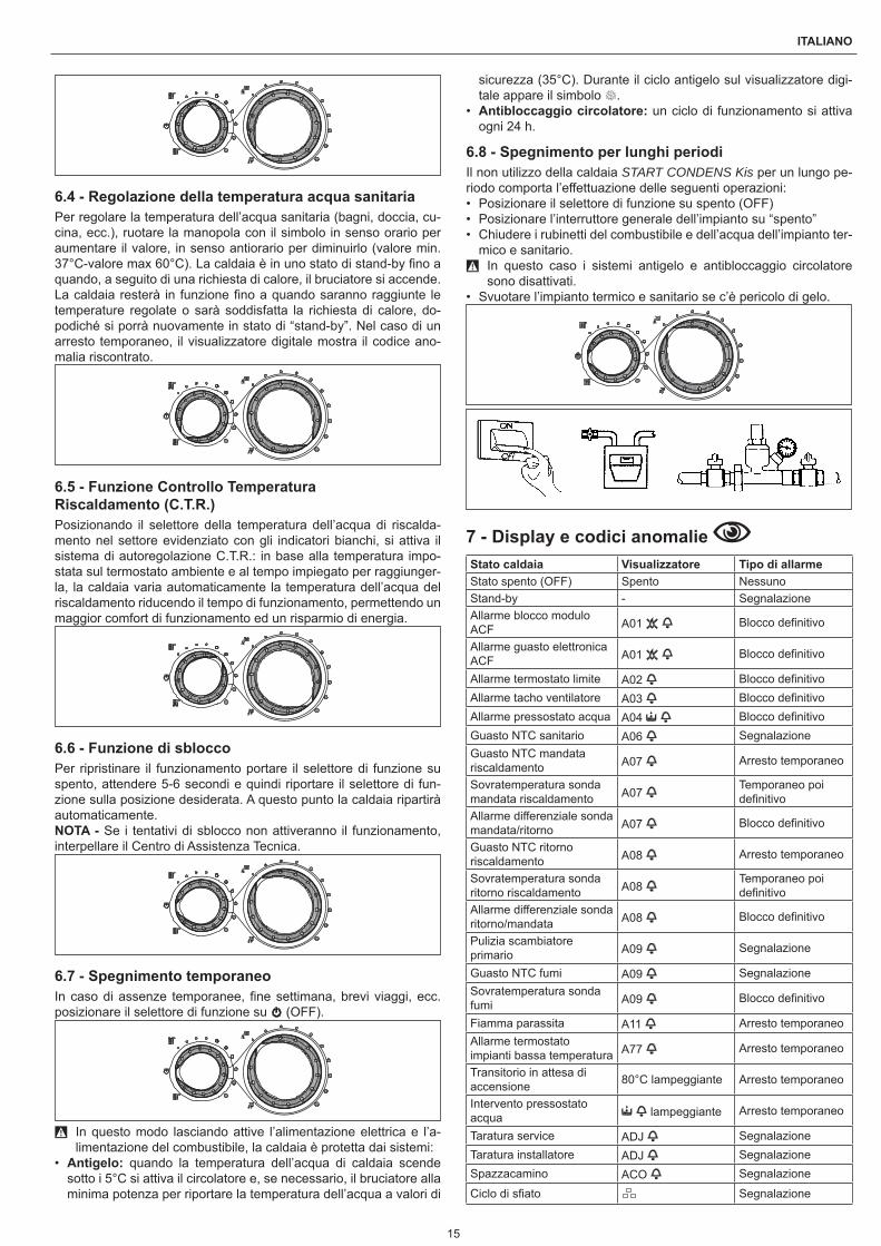
ITALIANO
6.4 - Regolazione della temperatura acqua sanitariaPer regolare la temperatura dell’acqua sanitaria (bagni, doccia, cu-cina, ecc.), ruotare la manopola con il simbolo in senso orario per aumentare il valore, in senso antiorario per diminuirlo (valore min. 37°C-valore max 60°C). La caldaia è in uno stato di stand-by fino a quando, a seguito di una richiesta di calore, il bruciatore si accende. La caldaia resterà in funzione fino a quando saranno raggiunte le temperature regolate o sarà soddisfatta la richiesta di calore, do-podiché si porrà nuovamente in stato di “stand-by”. Nel caso di un arresto temporaneo, il visualizzatore digitale mostra il codice ano-malia riscontrato.
6.5 - Funzione Controllo Temperatura Riscaldamento (C.T.R.)Posizionando il selettore della temperatura dell’acqua di riscalda-mento nel settore evidenziato con gli indicatori bianchi, si attiva il sistema di autoregolazione C.T.R.: in base alla temperatura impo-stata sul termostato ambiente e al tempo impiegato per raggiunger-la, la caldaia varia automaticamente la temperatura dell’acqua del riscaldamento riducendo il tempo di funzionamento, permettendo un maggior comfort di funzionamento ed un risparmio di energia.
6.6 - Funzione di sbloccoPer ripristinare il funzionamento portare il selettore di funzione su spento, attendere 5-6 secondi e quindi riportare il selettore di fun-zione sulla posizione desiderata. A questo punto la caldaia ripartirà automaticamente.NOTA - Se i tentativi di sblocco non attiveranno il funzionamento, interpellare il Centro di Assistenza Tecnica.
6.7 - Spegnimento temporaneoIn caso di assenze temporanee, fine settimana, brevi viaggi, ecc. posizionare il selettore di funzione su (OFF).
9 In questo modo lasciando attive l’alimentazione elettrica e l’a-limentazione del combustibile, la caldaia è protetta dai sistemi:
• Antigelo: quando la temperatura dell’acqua di caldaia scende sotto i 5°C si attiva il circolatore e, se necessario, il bruciatore alla minima potenza per riportare la temperatura dell’acqua a valori di
sicurezza (35°C). Durante il ciclo antigelo sul visualizzatore digi-tale appare il simbolo .
• Antibloccaggio circolatore: un ciclo di funzionamento si attiva ogni 24 h.
6.8 - Spegnimento per lunghi periodiIl non utilizzo della caldaia START CONDENS Kis per un lungo pe-riodo comporta l’effettuazione delle seguenti operazioni:• Posizionare il selettore di funzione su spento (OFF)• Posizionare l’interruttore generale dell’impianto su “spento”• Chiudere i rubinetti del combustibile e dell’acqua dell’impianto ter-
mico e sanitario. 9 In questo caso i sistemi antigelo e antibloccaggio circolatore
sono disattivati.• Svuotare l’impianto termico e sanitario se c’è pericolo di gelo.
7 - Display e codici anomalie Stato caldaia Visualizzatore Tipo di allarmeStato spento (OFF) Spento NessunoStand-by - SegnalazioneAllarme blocco modulo ACF A01 Blocco definitivo
Allarme guasto elettronica ACF A01 Blocco definitivo
Allarme termostato limite A02 Blocco definitivoAllarme tacho ventilatore A03 Blocco definitivoAllarme pressostato acqua A04 Blocco definitivoGuasto NTC sanitario A06 SegnalazioneGuasto NTC mandata riscaldamento A07 Arresto temporaneo
Sovratemperatura sonda mandata riscaldamento A07
Temporaneo poi definitivo
Allarme differenziale sonda mandata/ritorno A07 Blocco definitivo
Guasto NTC ritorno riscaldamento A08 Arresto temporaneo
Sovratemperatura sonda ritorno riscaldamento A08
Temporaneo poi definitivo
Allarme differenziale sonda ritorno/mandata A08 Blocco definitivo
Pulizia scambiatore primario A09 Segnalazione
Guasto NTC fumi A09 SegnalazioneSovratemperatura sonda fumi A09 Blocco definitivo
Fiamma parassita A11 Arresto temporaneoAllarme termostato impianti bassa temperatura A77 Arresto temporaneo
Transitorio in attesa di accensione 80°C lampeggiante Arresto temporaneo
Intervento pressostato acqua lampeggiante Arresto temporaneo
Taratura service ADJ SegnalazioneTaratura installatore ADJ SegnalazioneSpazzacamino ACO Segnalazione
Ciclo di sfiato Segnalazione

16
START CONDENS 25 - 29 Kis
Stato caldaia Visualizzatore Tipo di allarmeFunzione Preriscaldo attiva SegnalazioneRichiesta di calore preriscaldo lampeggiante Segnalazione
Presenza sonda esterna SegnalazioneRichiesta di calore sanitario 60°C Segnalazione
Richiesta di calore riscaldamento 80°C Segnalazione
Richiesta di calore antigelo SegnalazioneFiamma presente Segnalazione
Per ristabilire il funzionamento (sblocco allarmi):
Anomalie A01-02-03Posizionare il selettore di funzione su spento (OFF), attendere 5-6 secondi e riportarlo nella posizione desiderata.Se i tentativi di sblocco non riattiveranno la caldaia, chiedere l’inter-vento del Servizio Tecnico di Assistenza.
Anomalia A 04Il display digitale visualizza oltre al codice anomalia, il simbolo .Verificare il valore di pressione indicato dall’idrometro: se è inferiore a 0,3 bar posizionare il selettore di funzione su spento (OFF) e agire sul rubinetto di riempimento finché la pressione raggiunge un valore compreso tra 1 e 1,5 bar. Posizionare successivamente il se-lettore di funzione nella posizione desiderata.La caldaia effettuerà un ciclo di sfiato della durata di circa 2 minuti. Se i cali di pressione sono frequenti, chiedere l’intervento del Servi-zio Tecnico di Assistenza.
Anomalia A 06La caldaia funziona normalmente, ma non garantisce la stabilità del-la temperatura acqua sanitaria che resta impostata intorno a una temperatura prossima a 50°C.È richiesto l’intervento del Servizio Tecnico di Assistenza.
Anomalia A 07-A 08Chiedere l’intervento del Servizio Tecnico di Assistenza.
Anomalia A 09Posizionare il selettore di funzione su spento (OFF), attendere 5-6 secondi e riportarlo nella posizione desiderata.Se i tentativi di sblocco non riattiveranno la caldaia, chiedere l’inter-vento del Servizio Tecnico di Assistenza.
Anomalia A 09La caldaia dispone di un sistema di autodiagnosi che è in grado, sul-la base delle ore totalizzate in particolari condizioni di funzionamen-to, di segnalare la necessità di intervento per la pulizia dello scam-biatore primario (codice allarme 09 e contatore sonda fumi >2.500).Ultimata l’operazione di pulizia, effettuata con l’apposito kit fornito come accessorio, è necessario azzerare il contatore delle ore tota-lizzate applicando la seguente procedura:• Togliere l’alimentazione elettrica• Rimuovere il mantello• Ruotare il cruscotto dopo aver svitato la relativa vite di fissaggio• Svitare le viti di fissaggio del coperchietto per accedere alla mor-
settieraMentre si alimenta elettricamente la caldaia premere il tasto CO per almeno 4 secondi per verificare l’avvenuto azzeramento del conta-tore togliere e ridare tensione alla caldaia; sul visualizzatore il valore del contatore viene visualizzato dopo la segnalazione “- C -”.
9 Parti elettriche in tensione (230 Vac).NOTA - La procedura di azzeramento del contatore deve essere effettuata dopo ogni pulizia accurata dello scambiatore primario o in caso di sostituzione dello stesso. Per verificare lo stato delle ore totalizzate moltiplicare x100 il valore letto (es. valore letto 18 = ore totalizzate 1800 – valore letto 1= ore totalizzate 100).La caldaia continua a funzionare normalmente anche con allarme attivo.
Anomalia A 77L’anomalia è autoripristinante, se la caldaia non si riattiva chiedere l’intervento del Servizio Tecnico di Assistenza.
8 - Manutenzione La manutenzione periodica è un “obbligo” previsto dal DPR 16 Apri-le 2013 n°74 ed è essenziale per la sicurezza, il rendimento e la durata della caldaia.Essa consente di ridurre i consumi, le emissioni inquinanti e di man-tenere il prodotto affidabile nel tempo.Prima di iniziare le operazioni di manutenzione:• Effettuare l’analisi dei prodotti della combustione per verificare
lo stato di funzionamento della caldaia poi togliere l’alimentazio-ne elettrica posizionando l’interruttore generale dell’impianto su “spento”
• Chiudere i rubinetti del combustibile e dell’acqua dell’impianto ter-mico e sanitario.
9 Dopo aver effettuato le operazioni di manutenzione necessarie devono essere ripristinate le regolazioni originali ed effettuata l’analisi dei prodotti della combustione per verificare il corretto funzionamento.
9 Dopo gli interventi di manutenzione ordinaria o straordinaria pro-cedere al riempimento del sifone, seguendo quanto indicato nel paragrafo “Controllo prima della messa in servizio”.
8.1 - Pulizia caldaiaPrima di qualsiasi operazione di pulizia togliere l’alimentazione elet-trica posizionando l’interruttore generale dell’impianto su “spento”.
Pulizia esternaPulire il mantello, il pannello di comando, le parti verniciate e le parti in plastica con panni inumiditi con acqua e sapone.Nel caso di macchie tenaci inumidire il panno con miscela al 50% di acqua ed alcool denaturato o prodotti specifici.
0 Non utilizzare carburanti e/o spugne intrise con soluzioni abrasi-ve o detersivi in polvere.
Pulizia internaPrima di iniziare le operazioni di pulizia interna:• Chiudere i rubinetti di intercettazione del gas• Chiudere i rubinetti degli impianti.

17
ITALIANO
9 - Dati tecniciDescrizione Start Condens 25 Kis Start Condens 29 Kis
Combustibile G20 G230 G31 G20 G230 G31Categoria apparecchio II2HM3PPaese di destinazione IT
Tipo apparecchio B23P, B53P, C13-C13x, C23, C33-C33x, C43-C43x, C53-C53x, C83-C83x, C93-C93x
RiscaldamentoPortata termica nominale kW 20,00 25,00Potenza termica nominale (80/60°C) kW 19,50 24,45Potenza termica nominale (50/30°C) kW 20,84 26,23Portata termica ridotta kW 5,00 6,00Potenza termica ridotta (80/60°C) kW 4,91 5,90Potenza termica ridotta (50/30°C) kW 5,36 6,40Portata termica nominale Range Rated (Qn) kW 20,00 25,00Portata termica minima Range Rated (Qm) kW 5,00 6,00SanitarioPortata termica nominale kW 25,00 29,00Potenza termica nominale (*) kW 25,00 29,00Portata termica ridotta kW 5,00 6,00Potenza termica ridotta (*) kW 5,00 6,00RendimentiRendimento utile Pn max - Pn min (80/60°C) % 97,5 - 98,1 97,8 - 98,3Rendimento utile 30% (47°C ritorno) % 102,2 102,0Rendimento utile Pn max - Pn min (50/30°C) % 104,2 - 107,2 104,9 - 106,7Rendimento utile 30% (30°C ritorno) % 108,9 108,4Rendimento a Pn media Range Rated (80/60°C) % 97,8 98,0Rendimento a Pn media Range Rated (50/30°C) % 106,0 106,1Rendimento di combustione % 97,9 98,1Prevalenza residua caldaia senza tubi Pa 100 110Portate riscaldamentoPortata massica fumi potenza massima g/s 9,025 8,727 8,410 11,282 10,807 10,513Portata massica fumi potenza minima g/s 2,140 2,084 2,103 2,568 2,594 2,523Portata aria Nm3/h 24,908 23,626 24,192 31,135 29,248 30,240Portata fumi Nm3/h 26,914 25,177 24,267 33,642 31,187 31,209Indice eccesso d’aria (λ) potenza massima % 1,304 1,336 1,311 1,304 1,323 1,311Indice eccesso d’aria (λ) potenza minima % 1,235 1,274 1,311 1,235 1,323 1,311Portate sanitarioPortata massica fumi potenza massima g/s 11,282 10,908 10,513 13,087 12,536 12,195Portata massica fumi potenza minima g/s 2,140 2,084 2,103 2,568 2,594 2,523Portata aria Nm3/h 31,135 29,532 30,240 36,116 33,928 35,078Portata fumi Nm3/h 33,642 31,471 31,209 39,025 36,177 36,203Indice eccesso d’aria (λ) potenza massima % 1,304 1,871 1,311 1,304 1,323 1,311Indice eccesso d’aria (λ) potenza minima % 1,235 1,274 1,311 1,235 1,323 1,311EmissioniCO2 al massimo/minimo % 9,0 - 9,5 10,3 - 10,8 10,5 - 10,5 9,0 - 9,5 10,4 - 10,4 10,5 - 10,5CO S.A. al massimo/minimo inferiore a ppm 180 - 20 220 - 30 190 - 20 160 - 20 200 - 30 250 - 25NOx S.A. al massimo/minimo inferiore a ppm 30 - 20 45 - 50 35 - 35 35 - 25 40 - 35 50 - 40Temperatura fumi (potenza max/min) °C 65 - 58 62 - 52 62 - 55 63 - 58 64 - 57 62 - 56Classe NOx 5 5Esercizio riscaldamentoPressione massima di esercizio riscaldamento bar 3 3Pressione minima per funzionamento standard bar 0,25 - 0,45 0,25 - 0,45Temperatura massima ammessa °C 90 90Campo di selezione temperatura acqua caldaia °C 20/45 - 40/80 20/45 - 40/80Alimentazione elettrica Volt-Hz 230/50 230/50Vaso di espansione l 8 8Precarica vaso di espansione bar 1 1Parametri elettriciPotenza elettrica complessiva riscaldamento W 68 77Potenza elettrica complessiva sanitario W 82 89Potenza elettrica circolatore (1.000 l/h) W 39 39Grado di protezione elettrica IP X5D X5D
(*) Valore medio tra varie condizioni di funzionamento in sanitario

18
START CONDENS 25 - 29 Kis
9.1 - Descrizione sanitario
Descrizione Start Condens 25 Kis Start Condens 29 KisEsercizio sanitarioPressione massima bar 6 6Pressione minima bar 0,15 0,15Quantità di acqua calda con ∆t 25°C l/min 14,3 16,6Quantità di acqua calda con ∆t 30°C l/min 11,9 13,9Quantità di acqua calda con ∆t 35°C l/min 10,2 11,9Campo di selezione temperatura acqua sanitaria (± 3°C) °C 37 - 60 37 - 60Portata minima acqua sanitaria l/min 2 2Regolatore di flusso l/min 10 12
9.2 - Tabella multigas
Descrizione Gas metano (G20) Aria propanata (G230) Propano (G31)
Indice di Wobbe inferiore (a 15°C-1013 mbar) MJ/m3S 45,67 38,90 70,69Potere calorifico inferiore MJ/m3S 34,02 43,86 88
Pressione nominale di alimentazione mbarmm C.A.
20203,9
20203,9
37377,3
Pressione minima di alimentazione mbarmm C.A.
10102,0
Start Condens 25 KisNumero fori diaframma n° 1 1 1Diametro fori diaframma Ø mm 4,8 5,4 3,8
Portata gas massima riscaldamento Sm3/hkg/h
2,12-
1,64-
-1,55
Portata gas massima sanitario Sm3/hkg/h
2,64-
2,05-
-1,94
Portata gas minima riscaldamento Sm3/hkg/h
0,53-
0,41-
-0,39
Portata gas minima sanitario Sm3/hkg/h
0,53-
0,41-
-0,39
Numero giri ventilatore lenta accensione giri/min 4.000 4.000 4.000Numero giri ventilatore massimo riscaldamento giri/min 4.900 4.900 4.900Numero giri ventilatore massimo sanitario giri/min 6.100 6.100 6.100Numero giri ventilatore minimo riscaldamento giri/min 1.400 1.400 1.400Numero giri ventilatore minimo sanitario giri/min 1.400 1.400 1.400Start Condens 29 KisNumero fori diaframma n° 1 1 1Diametro fori diaframma Ø mm 5,1 5,8 3,9
Portata gas massima riscaldamento Sm3/hkg/h
2,64-
2,05-
-1,94
Portata gas massima sanitario Sm3/hkg/h
3,07-
2,38-
-2,25
Portata gas minima riscaldamento Sm3/hkg/h
0,63-
0,49-
-0,47
Portata gas minima sanitario Sm3/hkg/h
0,63-
0,49-
-0,47
Numero giri ventilatore lenta accensione giri/min 4.000 4.000 4.000Numero giri ventilatore massimo riscaldamento giri/min 5.300 5.200 5.200Numero giri ventilatore massimo sanitario giri/min 6.200 6.000 6.000Numero giri ventilatore minimo riscaldamento giri/min 1.400 1.400 1.400Numero giri ventilatore minimo sanitario giri/min 1.400 1.400 1.400
9.3 - Tabella dati ErP
Parametro Simbolo Start Condens 25 Kis
Start Condens 29 Kis Unità
Classe di efficienza energetica stagionale del riscaldamento d’ambiente A A
Classe di efficienza energetica di riscaldamento dell’acqua A APotenza nominale Pn 20 24 kWEfficienza energetica stagionale del riscaldamento d’ambiente ηs 93 93 %Potenza termica utileAlla potenza termica nominale e a un regime di alta temperatura (*) P4 19,5 24,5 kWAl 30% della potenza termica nominale e a un regime di bassa temperatura (**) P1 6,5 8,1 kW
EfficienzaAlla potenza termica nominale e a un regime di alta temperatura (*) η4 88,1 88,2 %

19
ITALIANO
Parametro Simbolo Start Condens 25 Kis
Start Condens 29 Kis Unità
Al 30% della potenza termica nominale e a un regime di bassa temperatura (**) η1 98,1 97,6 %
Consumi elettrici ausiliariA pieno carico elmax 29,0 38,0 WA carico parziale elmin 10,4 13,1 WIn modalità Standby PSB 2,4 2,4 WAltri parametriPerdite termiche in modalità standby Pstby 40,0 35,0 WConsumo energetico della fiamma pilota Pign - - WConsumo energetico annuo QHE 38 47 GJLivello della potenza sonora all’interno LWA 50 55 dBEmissioni di ossidi d’azoto NOx 19 23 mg/kWhAcqua calda sanitariaProfilo di carico dichiarato XL XLConsumo giornaliero di energia elettrica Qelec 0,183 0,197 kWhConsumo annuo di energia elettrica AEC 40 43 kWhEfficienza energetica di riscaldamento dell’acqua ηwh 85 84 %Consumo giornaliero di combustibile Qfuel 22,920 23,021 kWhConsumo annuo di combustibile AFC 17 17 GJ
(*) Regime di alta temperatura: 60°C al ritorno e 80°C alla mandata della caldaia.(**) Regime di bassa temperatura: temperatura di ritorno 30°C.
NOTACon riferimento al regolamento delegato (UE) N. 811/2013, i dati rappresentati nella tabella possono essere utilizzati per il completamento della scheda di prodotto e l’etichettatura per apparecchi per il riscaldamento d’ambiente, degli apparecchi per il riscaldamento misti, degli insiemi di apparecchi per il riscaldamento d’ambiente, per i dispositivi di controllo della temperatura e i dispositivi solari:Sonda esterna abbinata in caldaia
Componente Classe BonusSonda esterna II 2%Pannello comandi V 3%Sonda esterna + pannello comandi VI 4%
20
START CONDENS 25 - 29 Kis
EN ENGLISH
1 - Warnings and safety1.1 - General warnings
9 To guarantee the correct water output in the exchanger, the boil-ers are equipped with an automatic by-pass.
9 After removing the packaging, check the integrity and complete-ness of the supply and, otherwise, contact the Agency that sold the boiler.
9 The installation of the START CONDENS Kis boiler must be per-formed by a qualified company in accordance with current regu-lations that will issue the owner with the installation declaration of conformity on completion of the work, in compliance with the applicable Standards and the instructions supplied by r in the present instruction booklet.
9 The installer must instruct the user about the operation of the appliance and about essential safety regulations.
9 The boiler must be destined for the intended use for which it was purposely designed. The manufacturer accepts no liability within or without the contract for any damage caused to people, animals and property due to installation, adjustment and mainte-nance errors or to improper use.
9 In case of water leakage, close the water supply and immedi-ately contact the Technical Assistance Service or professionally qualified personnel.
9 From time to time, check the icon does not light up on the dis-play; this symbol indicates an incorrect charge pressure. Other-wise, refer to paragraph "Smart system filling".
9 Not using the boiler for an extended period of time involves the execution of at least the following operations:• turn the main appliance switch and the main system switch
to "off"• Close the fuel and water taps of the heating system• Drain the heating and domestic hot water circuits if there is a
risk of freezing. 9 The boiler maintenance must be carried out at least once a year. 9 This booklet and that of the User are an integral part of the ap-
pliance and therefore should be carefully preserved and should always accompany the boiler even when it is sold to another owner or user or when transferred to another system. In case of loss or damage, please contact your local Technical Assistance Service for a new copy.
9 The boilers are constructed so as to protect both the user and the installer from any accidents. After each intervention on the product, pay special attention to the electrical connections, es-pecially the stripped parts of the wires, which must not protrude from the terminal board in any way.
9 Dispose of all the packaging materials in the suitable containers at the corresponding collection centres.
9 Dispose of waste by being careful not to harm human health and without employing procedures or methods which may damage the environment.
9 At the end of its life, the product should be not be disposed of as solid urban waste, but rather it should be handed over to a differentiated waste collection centre.
9 Regularly check that the discharge manifold is not blocked by solid residues that might prevent the outflow of condensate water.
9 Sealing of the condensate drainage connection line must be guaranteed.
9 The intervention of the safety devices indicates a boiler mal-function, therefore immediately contact the Technical Assistance Service.
9 Replacement of safety devices must be performed by the Tech-nical Assistance Service, by exclusively using original manufac-turer components and referring to the spare parts list accompa-nying the boiler.
1.2 - Basic safety rules 0 Remember that the use of products requiring fuels, electricity
and water necessitates the respect of certain basic safety rules such as:
0 It is forbidden for children and unassisted unskilled people to use the boiler.
0 It is forbidden to activate electric devices or appliances such as switches, household appliances and so on if you notice a smell of fuel or unburnt fuel.
0 In this case:• Ventilate the room by opening the doors and windows• Close the fuel shut-off device• Request the prompt intervention of the Technical Assistance
Service or professionally qualified personnel. 0 It is forbidden to touch the boiler while barefoot or if parts of your
body are wet. 0 It is forbidden to carry out any cleaning operations before discon-
necting the boiler from the electricity supply; to do this, turn the main system switch to “OFF”.
0 It is forbidden to modify safety and adjustment devices without the boiler manufacturer's permission and relative instructions.
0 It is forbidden to pull, detach or twist the electric cables that emerge from the boiler, even if the boiler itself is disconnected from the mains supply.
0 It is forbidden to plug or reduce the size of any openings used for airing the installation area.
0 It is forbidden to leave flammable containers and substances in the room where the boiler is installed.
0 It is forbidden to disperse and leave packaging material within children's reach as it may be a potential source of hazard.
0 It is forbidden to obstruct the condensate outlet. 0 The boiler must not be put in service, even temporarily, with
non-operating or tampered safety devices.
1.3 - BOILER descriptionSTART CONDENS Kis are a wall-hung condensing boiler with pre-mix burner and low emission of pollutants for heating and for DHW, equipped with a stainless steel plate heat exchanger. These are electronically controlled boilers with automatic ignition, ionisation flame check and with proportional control system of the gas and air flows, both in heating and DHW.
2 - Installation2.1 - Receiving the productSTART CONDENS Kis boilers are supplied in single package pro-tected by cardboard packaging.The boiler is supplied as standard with the following material:• Installer's and user's instructions booklet.• Bar code labels.• Flue gas analysis adaptor plug.• Supporting cross-member.
9 The instruction booklet is an integral part of the boiler and should therefore be read and kept in a safe place.
2.2 - Installation roomIn configuration C, the appliance can be installed in any type of room and there are no limitations due to ventilation conditions or room volume since START CONDENS Kis are boilers with an "airtight" combustion circuit in relation to the installation environment.In configuration B23P, B53P the appliance cannot be installed in bedrooms, bathrooms, showers or where there are open fireplaces without a proper air flow. The room where the boiler is installed must have proper ventilation.
9 Consider the clearances necessary to access safety and adjust-ment devices and to perform maintenance operations.
9 Check that the electric protection level of the appliance is adapt-ed to the installation room characteristics.
9 In case the boilers are supplied with fuel gas of a specific weight greater than that of the air, the electric parts will have to be placed at a level above the ground greater than 500 mm.
21
ENGLISH
2.3 - Installation on appliances that are old or that need to be updatedWhen the START CONDENS Kis boilers are installed in old systems or systems to refurbish, check that:• The smoke pipe is suitable for the temperature of the combus-
tion products with condensation, calculated and built according to Standard, is as straight as possible, airtight, insulated and has no blockages or narrow sections. It is equipped with appropriate condensate collection and discharge systems.
• The electrical system is installed in compliance with the specific standards and by qualified personnel.
• The fuel supply line and eventual tank (LPG) are made according to specific Standards.
• The expansion tank ensures the total absorption of the dilatation of the fluid contained in the system.
• The flow rate and head of the circulator are suitable to the charac-teristics of the system.
• The system has been washed and cleaned of mud and grime, de-aerated and water tight.
• The boiler condensate drain system (siphon) is connected and routed to the collection of "white" water.
• There is a treatment system for when the supply/make-up water is particular (the values in the table can be used as reference values).
Supply water valuespH 6-8Electric conductivity less than 200 μS/cm (25 °C)Chlorine ions less than 50 ppmSulphuric acid ions less than 50 ppmTotal iron less than 0.3 ppmM alkalinity less than 50 ppmTotal hardness less than 35°FSulphur ions NoneAmmonia ions NoneSilicon ions less than 20 ppm
9 The manufacturer is not liable for any damage resulting from the incorrect construction of the flue gas discharge system.
9 The flue gas discharge pipes for condensing boilers are made of special materials that are different compared to those made for standard boilers.
2.4 - Water characteristics of the DHW circuit 9 If consumption water has a total hardness between 25° F and
50° F, install a DHW treatment kit; with a total hardness great-er than 50° F, the kit's effectiveness progressively reduces and therefore the use of an appliance of higher performance or total softening is recommended; even with a total hardness of less than 25° F, a filter of appropriate size must be installed if the wa-ter comes from the mains that is not perfectly clean/cleanable.
2.5 - Boiler installation (fig. 2)For a correct installation, keep in mind that:• The boiler must not be placed above a stove or other cooking
appliance• It is forbidden to leave inflammable products in the room where
the boiler is installed• Heat-sensitive walls (e.g. wooden walls) must be protected with
proper insulation• The minimum clearances for technical and maintenance interven-
tions must be respected.START CONDENS Kis boilers may be installed indoor or outdoor: in a partially protected place (i.e. a place where the boiler is not exposed to direct contact or infiltration of rain, snow or hail). The boiler can operate in a temperature range from -3°C to +60°C. For further details, refer to “Anti-freeze system” section.
Indoor installation (fig. 3)They may be installed in numerous rooms as long as the combus-tion product outlet and combustion air suction are brought outside the room itself. In this case, the room does not require any ventila-
tion opening because these are boilers with an "airtight" combustion circuit in relation to the installation environment.If, instead, the combustion air is picked up from the installation room, the latter must be equipped with ventilation openings compliant with Technical Standards and suitably dimensioned.Consider the clearances necessary to access safety and adjustment devices and to perform maintenance operations.Check that the electric protection level of the appliance is adapted to the installation room characteristics.In case the boilers are supplied with fuel gas of a specific weight greater than that of the air, the electric parts will have to be placed at a level above the ground greater than 500 mm.
Outdoor installation (fig. 4)The boiler must be installed in a partially protected place or, in other words, it must not be directly exposed to the action of the weather.The boiler is fitted as standard with an automatic anti-freeze system that activates when the temperature of the water in the primary cir-cuit falls below 6°C.To take advantage of this protection (based on burner operation), the boiler must be able to switch itself on; any lockout condition (for ex. due to a lack of gas or electrical supply, or the intervention of a safety device) therefore deactivates the protection.
Anti-freeze systemThe boiler is fitted as standard with an automatic anti-freeze system that activates when the temperature of the water in the primary cir-cuit falls below 5°C.This system is always active, guaranteeing boiler protection down to an installation area temperature of -3°C.
9 To take advantage of this protection (based on burner opera-tion), the boiler must be able to switch itself on; any lockout con-dition (for ex. due to a lack of gas or electrical supply, or the inter-vention of a safety device) therefore deactivates the protection. The anti-freeze protection is also active when the boiler is on standby.
When the boiler is installed in a location with a risk of frost, with ex-ternal temperatures between -3° C and -10° C, an accessory must be requested for the protection of the DHW circuit, comprising a control thermostat and a series of electric heating elements with rel-ative wiring.
9 An electrical power supply is necessary in order to take advan-tage of this protection, implemented with electrically powered heating elements. this means that any blackout or disconnec-tion will deactivate the protection. The anti-freeze protection is also active when the boiler is on standby.
The assembly of the antifreeze heater kit must only be carried out by authorized personnel, following the instructions contained in the packaging of the kit.In normal operation conditions, the boiler can protect itself against freezing.
Outdoor installation in built-in box (fig. 5)The boiler can also be installed outside in the special built-in box.In this type of installation, the boiler can operate in a temperature range from 0°C to 60°C.
For outdoor installationIf the machine is left unpowered for long periods in areas where temperatures may fall below 0°C, and you do not want to drain the heating system, you are advised to add a specific, good quality an-ti-freeze liquid to the primary circuit.Carefully follow the manufacturer's instructions with regards not only the percentage of anti-freeze liquid to be used for the minimum tem-perature at which you want to keep the machine circuit, but also the duration and disposal of the liquid itself.For the domestic hot water part, we recommend you drain the circuit.The boiler component materials are resistant to ethylene glycol based antifreeze liquids.Specific anti-freeze kits are available for outdoor installations.
Pre-assembly templateThe boiler is supplied with a preassembly template which allows for realising the connections to the heating and domestic hot water

22
START CONDENS 25 - 29 Kis
system without the boiler, which may be subsequently assembled, standing in the way.Connect the discharge manifold to a suitable discharge system.START CONDENS Kis boilers are designed and made to be in-stalled on heating and domestic hot water production systems.The position and dimension of hydraulic fittings are shown in the drawings.• Position the cardboard template on the wall, with the aid of a spirit
level: check the correct horizontal plane and the planarity of the boiler rest surface; make it thicker if needed
• Trace the fixing points• Remove the template and carry out the drilling• Check the correct horizontality with a spirit level.
Fixing the boilerHook the boiler (fig. 6).
Hydraulic connections
86,5
140
65 50 80 65
M AC G R AF
58,5
M Heating deliveryAC Hot water outletG GasR Heating return lineAF Cold water inletSC Condensate drain
We recommend connecting the boiler to the systems introducing both the DHW shut-off valve as well as the shut-off valves for the heating system; for this purpose a heating system valves kit and heating valves kit with filter is available.
9 The selection and the installation of the system components are the responsibility of the installer, who must operate according to the rules of good technique and current Legislation.
Condensate collection (fig. 7)The system must be made so as to avoid any freezing of the con-densate produced by the boiler (e.g. by insulating it). You are ad-vised to install a special drainage collection basin in polypropylene, widely available on the market, on the lower part of the boiler (hole Ø 42), as shown in figure.Position the condensate discharge hose supplied with the boiler, connecting it to the manifold (or another examinable coupling de-vice) without creating kinks where condensate can stagnate and possibly freeze.The manufacturer will not be liable for any damage resulting from the failure to channel the condensate, or from its freezing.The drainage connection line must be perfectly sealed, and well pro-tected from the risk of freezing.Before the initial start-up of the appliance, check the condensate will be properly drained off.
2.6 - Installing the external probe (accessory)The correct operation of the external probe is fundamental for the good operation of the climatic control.
Installing and connecting the external probeThe probe must be installed on an external wall of the building to be heated, observing the following indications:
• It must be mounted on the side of the building most often exposed to winds (the NORTH or NORTHWEST facing wall), avoiding di-rect solar irradiation;
• It must be mounted about 2/3 of the way up the wall;• It must not be mounted near doors, windows, air outlet points, or
near smoke pipes or other heat sources.The electrical wiring to the external probe is made with a bipolar ca-ble with a section from 0.5 to 1mm2 (not supplied), with a maximum length of 30 metres. It is not necessary to respect the polarity of the cable when connecting it to the external probe. Avoid making any joints on this cable however; if joints are absolutely necessary, they must be watertight and well protected.Any ducting of the connection cable must be separated from live cables (230V AC).
Fixing the external probe to the wall (fig. 8)The probe must be fixed on a smooth part of the wall; in the case of exposed brickwork or an uneven wall, look for the smoothest possible area.• Loosen the plastic upper protective cover by turning it anticlockwise.• After deciding on the best fixing area of the wall, drill the holes for
the 5x25 wall plug.• Insert the plug in the hole.• Remove the card from its seat.• Fix the box to the wall, using the screw supplied.• Attach the bracket, then tighten the screw.• Loosen the nut of the cable grommet, then insert the probe con-
nection cable and connect it to the electric clamp.To make the electrical connection between the external probe and the boiler, refer to the “Electrical wiring” chapter.
9 Remember to close the cable grommet well, to prevent any air humidity getting in through the opening.
• Put the board back in its seat.• Close the plastic upper protective cover by turning it clockwise.
Tighten the cable grommet very well.
2.7 - Electrical wiringSTART CONDENS Kis boilers leave the factory completely wired and only need to be connected to the mains power supply (using the supplied power cable) and the ambient thermostat (TA) and/or timer, via relevant terminals.• Turn the main system switch to “OFF”.• Unscrew the housing fixing screws (A . fig. 9).• Move the housing base forwards and then upwards to unhook it
from the frame.• Unscrew the instrument panel fixing screws (B - fig. 10).• Turn the instrument panel forward.• Unscrew the fixing screws (C - fig. 11) to access the terminal
board. 9 Safety low voltage ambient thermostat input (clean contact). 9 In case of power supply between phases, check with a tester
which of the two wires has a greater potential in relation to the earth and connect it to the L and similarly connect the remaining wiring to the N.
9 The boiler can operate with a phase-neutral or phase-phase supply. For floating power supplies, i.e. that are not connected to ground/earth at origin, an isolating transformer with earth-an-chored secondary must be used.
9 Mandatory items:• Use an omnipolar magnetothermic switch, feeder disconnec-
tor, compliant with CEI-EN 60335-1 standards (contact open-ing of at least 3,5mm, category 3)
• use cables with a section ≥ 1.5mm2 and comply with the con-nection L (phase) - N (Neutral)
• The switch amperage must be adapted to the electric output of the boiler, refer to technical data to check the electric output of the model installed
• Connect the appliance to an effective grounding system• Safeguard access to the power socket after the installation
0 It is forbidden to use gas and water pipes for grounding the unit. 9 The manufacturer is not liable for any damage caused by failure
to comply with the wiring diagrams.

23
ENGLISH
9 The installer is responsible for ensuring the appliance is suitably earthed; the manufacturer will not be liable for any damage re-sulting from an incorrect or absent earth connection.
2.8 - Boiler configurationThe electronic board has a number of jumpers (JPX) that allow to configure the boiler.To access the board, proceed as follows:• Turn the main system switch OFF.• Unscrew the housing fixing screws (A - fig. 9).• Move the housing base forwards and then upwards to unhook it
from the frame.• Unscrew the instrument panel fixing screws (B - fig. 10).• Turn the instrument panel forward.• Unscrew the fixing screws (C - fig. 11) to access the terminal board.
Jumper JP7 (fig. 12)Pre-selection of the most appropriate heating temperature adjust-ment field based on the type of system.• Jumper not inserted: Standard system (40-80 °C).• Jumper inserted: Floor installation (20-45°C).During manufacture, the boiler is configured for standard systems.
Jumper DescriptionJP1 Calibration (Range Rated)JP2 Heating timer resetJP3 Calibration (see paragraph “Adjustments”)JP4 Absolute domestic hot water thermostat selectorJP5 Do not useJP6 Enable night-time compensation and continuous pump
function (only with outdoor probe connected)JP7 Enable standard system/low temperature management
(see above)JP8 Do not use
2.9 - Gas connectionThe connection of the START CONDENS Kis boiler to the gas supply must be carried out in the respect of current installation standards.Before carrying out the connection, it is necessary to ensure that:• The gas type is suitable for the appliance• The piping is thoroughly clean.
9 The gas feeding system must be adapted to the boiler output and must be equipped with all the safety and control devices pre-scribed by the current standards. The use of a filter of adequate dimensions is recommended.
9 Once the installation is done, check that the junctions carried out are sealed.
2.10 - flue gas outlet and combustion air suction
67,5 135 72 130,5
130
175
Suction/discharge pipes length table
Maximum straight length Pressure drop
25 Kis 29 Kis bend 45° bend 90°Flue gases pipe Ø 80 mm ("forced open” installation) (type B23P-B53P)
70m 65m 1m 1.5m
Concentric pipe Ø 60-100 mm (horizontal) 5.85m 4.85m 1.3m 1.6m
Maximum straight length Pressure drop
25 Kis 29 Kis bend 45° bend 90°Concentric pipe Ø 60-100 mm (vertical) 6.85m 5.85m 1.3m 1.6m
Concentric pipe Ø 80-125 mm 15.3m 12.8m 1m 1.5m
Twin pipe Ø 80 mm 45+45 m 40+40 m 1m 1.5m
9 "Straight length" means without bends, drainage terminals or joints.
9 It is compulsory to use specific pipes. 9 The non insulated flue gas outlet pipes are potential sources of
danger. 9 The use of a longer pipe causes a loss of output of the boiler. 9 Make sure the flue gas discharge pipe is tilted 3° towards the
boiler.
3°
Flue gases pipe Ø 80 mm ("forced open” installation) (type B23P-B53P)
262,
5
The appropriate adaptor kit must be installed for this configuration. The concentric pipes can be fitted in most suitable direction in rela-tion to installation requirements. For installation, follow the instruc-tions supplied with the specific kit for condensing boilers.Concentric pipes ø 60-100mm
130
100
Twin pipes ø 80mm
134
134
87 129
Air inlet adaptor kit Ø 80 mm
Air inlet adaptor kit from Ø 60 mm to
Ø 80 mm
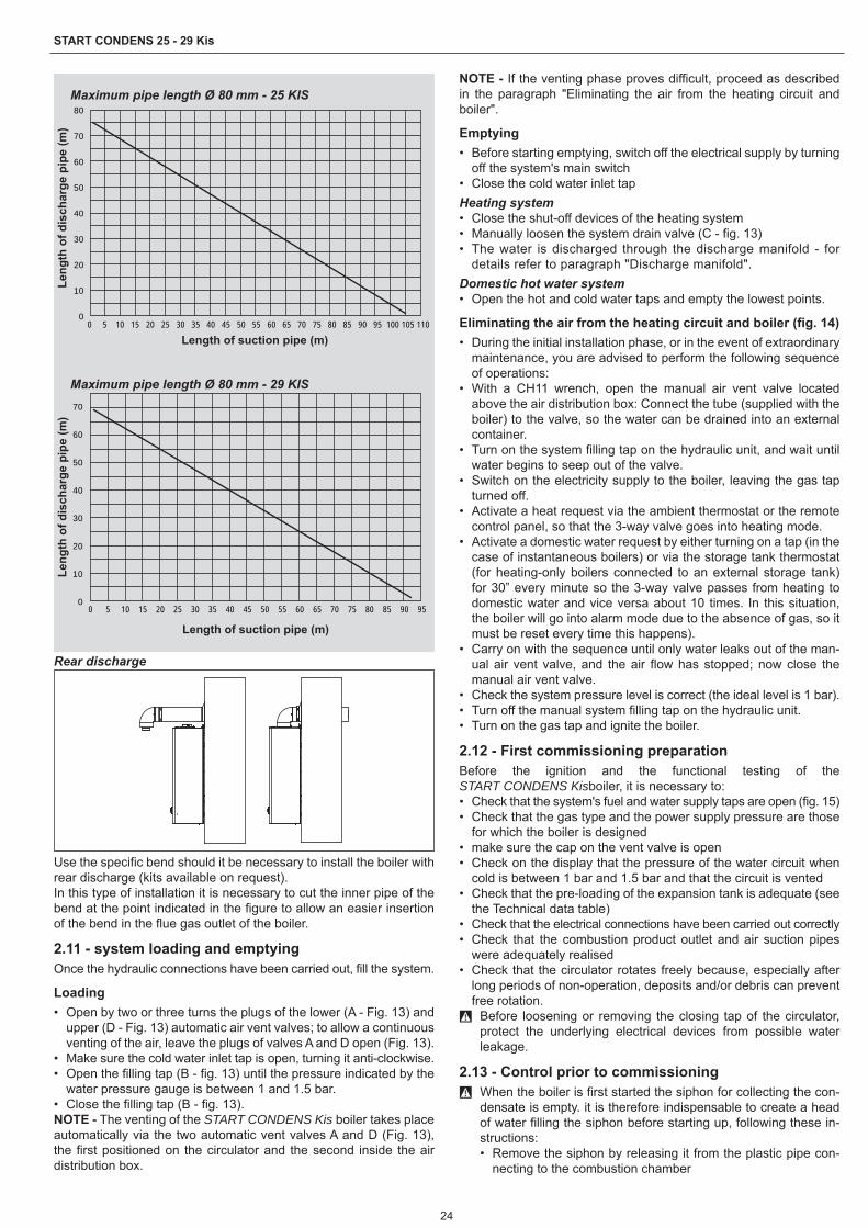
24
START CONDENS 25 - 29 Kis
Maximum pipe length Ø 80 mm - 25 KIS
0
10
20
30
40
50
60
70
80
0 5 10 15 20 25 30 35 40 45 50 55 60 65 70 75 80 85 90 95 100 105 110
Length of suction pipe (m)
Leng
th o
f dis
char
ge p
ipe
(m)
Maximum pipe length Ø 80 mm - 29 KIS
0
10
20
30
40
50
60
70
0 5 10 15 20 25 30 35 40 45 50 55 60 65 70 75 80 85 90 95
Length of suction pipe (m)
Leng
th o
f dis
char
ge p
ipe
(m)
Rear discharge
Use the specific bend should it be necessary to install the boiler with rear discharge (kits available on request).In this type of installation it is necessary to cut the inner pipe of the bend at the point indicated in the figure to allow an easier insertion of the bend in the flue gas outlet of the boiler.
2.11 - system loading and emptyingOnce the hydraulic connections have been carried out, fill the system.
Loading• Open by two or three turns the plugs of the lower (A - Fig. 13) and
upper (D - Fig. 13) automatic air vent valves; to allow a continuous venting of the air, leave the plugs of valves A and D open (Fig. 13).
• Make sure the cold water inlet tap is open, turning it anti-clockwise.• Open the filling tap (B - fig. 13) until the pressure indicated by the
water pressure gauge is between 1 and 1.5 bar.• Close the filling tap (B - fig. 13).NOTE - The venting of the START CONDENS Kis boiler takes place automatically via the two automatic vent valves A and D (Fig. 13), the first positioned on the circulator and the second inside the air distribution box.
NOTE - If the venting phase proves difficult, proceed as described in the paragraph "Eliminating the air from the heating circuit and boiler".
Emptying• Before starting emptying, switch off the electrical supply by turning
off the system's main switch• Close the cold water inlet tapHeating system• Close the shut-off devices of the heating system• Manually loosen the system drain valve (C - fig. 13)• The water is discharged through the discharge manifold - for
details refer to paragraph "Discharge manifold".Domestic hot water system• Open the hot and cold water taps and empty the lowest points.
Eliminating the air from the heating circuit and boiler (fig. 14)• During the initial installation phase, or in the event of extraordinary
maintenance, you are advised to perform the following sequence of operations:
• With a CH11 wrench, open the manual air vent valve located above the air distribution box: Connect the tube (supplied with the boiler) to the valve, so the water can be drained into an external container.
• Turn on the system filling tap on the hydraulic unit, and wait until water begins to seep out of the valve.
• Switch on the electricity supply to the boiler, leaving the gas tap turned off.
• Activate a heat request via the ambient thermostat or the remote control panel, so that the 3-way valve goes into heating mode.
• Activate a domestic water request by either turning on a tap (in the case of instantaneous boilers) or via the storage tank thermostat (for heating-only boilers connected to an external storage tank) for 30” every minute so the 3-way valve passes from heating to domestic water and vice versa about 10 times. In this situation, the boiler will go into alarm mode due to the absence of gas, so it must be reset every time this happens).
• Carry on with the sequence until only water leaks out of the man-ual air vent valve, and the air flow has stopped; now close the manual air vent valve.
• Check the system pressure level is correct (the ideal level is 1 bar).• Turn off the manual system filling tap on the hydraulic unit.• Turn on the gas tap and ignite the boiler.
2.12 - First commissioning preparationBefore the ignition and the functional testing of the START CONDENS Kisboiler, it is necessary to:• Check that the system's fuel and water supply taps are open (fig. 15)• Check that the gas type and the power supply pressure are those
for which the boiler is designed• make sure the cap on the vent valve is open• Check on the display that the pressure of the water circuit when
cold is between 1 bar and 1.5 bar and that the circuit is vented• Check that the pre-loading of the expansion tank is adequate (see
the Technical data table)• Check that the electrical connections have been carried out correctly• Check that the combustion product outlet and air suction pipes
were adequately realised• Check that the circulator rotates freely because, especially after
long periods of non-operation, deposits and/or debris can prevent free rotation. 9 Before loosening or removing the closing tap of the circulator,
protect the underlying electrical devices from possible water leakage.
2.13 - Control prior to commissioning 9 When the boiler is first started the siphon for collecting the con-
densate is empty. it is therefore indispensable to create a head of water filling the siphon before starting up, following these in-structions:• Remove the siphon by releasing it from the plastic pipe con-
necting to the combustion chamber

25
ENGLISH
• fill the siphon about 3/4” full with water, making sure it is free of any impurities
• check the float of the plastic cylinder• put back the siphon, being careful not to empty it, and secure
it with the clip.The plastic cylinder inside the siphon has the job of preventing combustible gas coming out into the surroundings if the appliance is started without first creating the head of water in the siphon. Re-peat this operation during routine and extraordinary maintenance operations.• Adjust the ambient temperature thermostat to the desired temper-
ature (~20°C) or, if the system is equipped with a programmable thermostat or timer, ensure that the thermostat or timer is "active" and set correctly (~20°C)
• A variety of information appears on the display for each power supply, including the value of the flue gases probe meter (-C- XX - see "Display and fault codes" - Fault A 09), the boiler will then start an automatic venting cycle of about 2 minutes
• The display shows the symbol .
To stop the automatic venting cycle, proceed as follows:• Access the electronic board by removing the housing, turning the
instrument panel forwards you and opening the terminal board cover (Fig. 16)
Then:• Press the CO button using the supplied screwdriver (fig. 16).
9 Live electrical parts (230 Vac).To start-up the boiler it is necessary to carry out the following operations:• power the boiler• Turn on the gas tap to allow fuel flow• Adjust the ambient thermostat to the required temperature (~20°C)• Turn the mode selector to the required position.
2.14 - Checks during and after the first commissioningFollowing commissioning, check that the START CONDENS Kis boiler performs the start-up procedures and subsequent shutdown properly by acting on the:• Mode selector• Calibration of the heating water temperature selector and domestic
hot water temperature selector• - Requested ambient temperature (by intervening on the ambient
thermostat or programming timer)Check the domestic hot water operation by opening a hot water tap with the mode selector both in summer and winter mode and in win-ter mode with preheating.Check the full stop of the boiler by turning off the system's main switch.After a couple of minutes of continuous operation to be obtained by turning on the system's main switch, the mode selector () on (summer) and by keeping open the domestic hot water device, the binders and manufacturing waste evaporate and it will be possible to perform:• The supply gas pressure check• The combustion check.
Supply gas pressure check• Turn the mode selector to to turn off the boiler
• Unscrew the housing fixing screws (A - fig. 9)• move the housing base forwards and then upwards to unhook it
from the frame• Unscrew the instrument panel fixing screws (B - fig. 10)• Turn the instrument panel forward
• Undo by two turns the screw of the pressure test point upstream from the gas valve (C - fig. 17) and connect the pressure gauge
• Power the boiler electrically by setting the main system switch to “ON”
• Bring the mode selector to summer• Turn the DHW temperature selector to maximum• Fully open the hot water tap• With the burner at maximum output, check that the gas pressure
is comprised between the minimum and rated power supply pres-sure values indicated in the multigas table
• Turn off the hot water tap• Disconnect the pressure gauge and tighten the pressure test point
screw again upstream from the gas valve.
Combustion checkTo carry out the combustion analysis, proceed as follows:• Set the main system switch to OFF• Unscrew the housing fixing screws (A - fig. 9)• move the housing base forwards and then upwards to unhook it
from the frame• Unscrew the instrument panel fixing screws (B - fig. 10)• Rotate the control panel towards you• Unscrew the fixing screws (C - fig. 11) to access the terminal board• Press the "CO" button once using the supplied screwdriver (fig. 16)
9 Live electrical parts (230 Vac).• Wait for the burner to fire. “ACO” is displayed and the boiler oper-
ates at the maximum heating output• Remove the screw and the cover on the air distribution box• Insert the analysis probe adapter, found in the documentation en-
velope, into the hole for the combustion analysis• Insert the flue gases analysis probe inside the adaptor• Check that the CO2 values correspond to those indicated in the
"Multigas" table, if the value displayed is different, modify as indi-cated in chapter "gas valve calibration.".
• Perform the combustion check.Then:• Remove the analyser probe and close the combustion analysis
sockets with the screw• Close the instrument panel and reposition the cover
9 The flue gas analysis probe should be inserted until its reaches the stop.
9 Even during the combustion analysis phase, the function that switches the boiler off when the water temperature reaches the maximum limit (about 90°C) remains enabled.
When checks are completed:• Position the mode selector depending on the operating mode desired• Adjust the selectors (2 and 3) according to the client's requirements.
9 START CONDENS Kis boilers are intended for use with meth-ane gas (G20) and are already factory set as specified on the rating plate, so do not require any calibration.
9 All checks must be carried out exclusively by the Technical As-sistance Service .
2.15 - Setting the thermoregulationThermoregulation only works with external sensor connected, so once installed, connect the outdoor probe - accessory on request - to the appropriate connections provided on the terminal board of the boiler. This will enable the THERMOREGULATION function.
Choice of the compensation curveThe compensation curve for heating maintains a theoretical temper-ature of 20°C indoors, when the external temperature is between +20°C and -20°C. The choice of the curve depends on the minimum external temperature envisaged (and therefore on the geographical location), and on the delivery temperature envisaged (and therefore on the type of system). It is carefully calculated by the installer on the basis of the following formula:
KT=T.outlet envisaged - Tshift
20 - min. design external T.
Tshift = 30°C standard system25°C floor installations
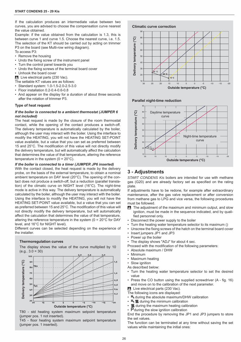
26
START CONDENS 25 - 29 Kis
If the calculation produces an intermediate value between two curves, you are advised to choose the compensation curve nearest the value obtained.Example: if the value obtained from the calculation is 1.3, this is between curve 1 and curve 1.5. Choose the nearest curve, i.e. 1.5. The selection of the KT should be carried out by acting on trimmer P3 on the board (see Multi-row wiring diagram).To access P3:• Remove the housing• Undo the fixing screw of the instrument panel• Turn the control panel towards you• Undo the fixing screws of the terminal board cover• Unhook the board cover
9 Live electrical parts (230 Vac).The settable KT values are as follows:• Standard system: 1.0-1.5-2.0-2.5-3.0• Floor installation 0.2-0.4-0.6-0.8• And appear on the display for a duration of about three seconds
after the rotation of trimmer P3.
Type of heat request
If the boiler is connected to a ambient thermostat (JUMPER 6 not included)The heat request is made by the closure of the room thermostat contact, while the opening of the contact produces a switch-off. The delivery temperature is automatically calculated by the boiler, although the user may interact with the boiler. Using the interface to modify the HEATING, you will not have the HEATING SET-POINT value available, but a value that you can set as preferred between 15 and 25°C. The modification of this value will not directly modify the delivery temperature, but will automatically affect the calculation that determines the value of that temperature, altering the reference temperature in the system (0 = 20°C).If the boiler is connected to a timer (JUMPER JP6 inserted)With the contact closed, the heat request is made by the delivery probe, on the basis of the external temperature, to obtain a nominal ambient temperature on DAY level (20°C). The opening of the con-tact does not produce a switch-off, but a reduction (parallel transla-tion) of the climatic curve on NIGHT level (16°C). The night-time mode is active in this way. The delivery temperature is automatically calculated by the boiler, although the user may interact with the boiler.Using the interface to modify the HEATING, you will not have the HEATING SET-POINT value available, but a value that you can set as preferred between 15 and 25°C. The modification of this value will not directly modify the delivery temperature, but will automatically affect the calculation that determines the value of that temperature, altering the reference temperature in the system (0 = 20°C for DAY level, and 16°C for NIGHT level).Different curves can be selected depending on the experience of the installer.
Thermoregulation curvesThe display shows the value of the curve multiplied by 10 (e.g.. 3.0 = 30)
Temperatura esterna (˚C)
Tem
pera
tura
di
man
data
(˚C
)
20
30
40
50
60
70
80
90
100
-20
0,2
0,4
0,6
0,8
1,0
1,5
2,02,53,0
T80
T45
-15-10-505101520
Outside temperature (°C)
Del
iver
y te
mpe
ratu
re (°
C)
T80 - std heating system maximum setpoint temperature (jumper pos. 1 not inserted).T45 - floor heating system maximum setpoint temperature (jumper pos. 1 inserted).
Climatic curve correction
20 °C25 ° C
15 °C
10
20
30
40
50
60
70
80
90
-20-15-10-5051015202530
Outside temperature (°C)
Del
iver
y te
mpe
ratu
re (°
C)
Parallel night-time reduction
10
20
30
40
50
60
70
80
90
-20-15-10-505101520Temperatura Esterna
Tem
per
atu
ra d
i
Curva climatica GIORNO
Curva climatica NOTTE
16 °C20 °C
Outside temperature (°C)
Night-time temperature curve
Daytime temperature curve
Del
iver
y te
mpe
ratu
re (°
C)
3 - AdjustmentsSTART CONDENS Kis boilers are intended for use with methane gas (G20) and are already factory set as specified on the rating plate.If adjustments have to be redone, for example after extraordinary maintenance, after the gas valve replacement or after conversion from methane gas to LPG and vice versa, the following procedures must be followed.
9 The adjustment of the maximum and minimum output, and slow ignition, must be made in the sequence indicated, and by quali-fied personnel only.
• Disconnect the power supply to the boiler• Turn the heating water temperature selector to its maximum ()• Unscrew the fixing screws of the hatch on the terminal board cover• Insert jumpers JP1 and JP3• Power up the boiler• The display shows "ADJ" for about 4 sec.Proceed with the modification of the following parameters:• Absolute maximum / DHW• Minimum• Maximum heating• Slow ignitionAs described below:• Turn the heating water temperature selector to set the desired
value• Press the CO button using the supplied screwdriver (A - fig. 16)
and move on to the calibration of the next parameter. 9 Live electrical parts (230 Vac).
The following icons are displayed:• during the absolute maximum/DHW calibration• during the minimum calibration• during the maximum heating calibration• during the slow ignition calibrationEnd the procedure by removing the JP1 and JP3 jumpers to store the set values.The function can be terminated at any time without saving the set values while maintaining the initial ones:

27
ENGLISH
• Removing jumpers JP1 and JP3 before all 4 parameters have been set
• Turning the mode selector to OFF/RESET• Removing the mains voltage 15 minutes after its activation.
9 The calibration does not entail the ignition of the boiler. 9 By rotating the heating selector knob, the number of revolutions
expressed in hundreds (e.g. 25 = 2500 rpm) is automatically displayed.
The calibration parameter display function is activated with the se-lector on summer or winter by pressing the CO button (A - fig. 16) on the board regardless of whether or not there is a heat request. The function cannot be activated if a remote control is connected.When this function is activated, the calibration parameters each ap-pear (in the order shown below) for 2 seconds. The relative icon is indicated in line with each parameter, and the fan rotation value (expressed in hundreds)• Maximum• Minimum• Maximum heating• Slow ignition• Maximum heating adjusted
3.1 - Gas valve calibration• Power the boiler• Open the gas tap• Turn the mode selector to OFF/RESET (display off)• Remove the housing and turn the control panel• Undo the fixing screws of the cover to access the terminal board• Press the “CO” button (A - fig. 16) once
9 Live electrical parts (230 Vac).• Wait for the burner to fire. “ACO” is displayed. The boiler operates
at the maximum heating output. The "combustion analysis" func-tion is active for a time limit of 15 minutes; the burner shuts down if an outlet temperature of 90° C is reached. It will ignite again when the temperature falls below 78° C.
• Remove the screw (A - fig. 18) and cover (B - fig. 18) on the air distribution box
• Insert the analysis probe adapter, found in the documentation en-velope, into the hole for the combustion analysis (C - fig. 18)
• Insert the flue gases analysis probe inside the adaptor• Press the "combustion analysis" button a second time to reach the
rpm corresponding to the maximum DHW output (see the multi-gas table)
• Check the CO2 value: (refer to the Multigas table) if the value does not comply to what is reported in the table, act on the max adjust-ing screw of the gas valve (A - Fig. 19)
• Press the "combustion analysis" button a third time to reach the rpm corresponding to the minimum output (see the multigas table).
• Check the CO2 value: (refer to the Multigas table) if the value does not comply to what is reported in the table, act on the min. adjust-ing screw of the gas valve (B - Fig. 19)
• Turn the control knob to exit the "combustion analysis" mode• Pull out the flue gas analysis probe and replace the plug.• Close the instrument panel and reposition the cover• The "combustion analysis" function is automatically disabled if the
card generates an alarm. In the event of an anomaly during the combustion analysis phase, perform the reset procedure.
4 - Range ratedThis boiler can be adapted to the heating requirements of the sys-tem, in fact it is possible to set the maximum delivery for heating operation of the boiler itself:• Disconnect the power supply to the boiler• Turn the heating water temperature selector to its maximum ()• Remove the housing and turn the instrument panel (refer to previ-
ous chapters for the detail of the figures)• Unscrew the fixing screws of the hatch on the terminal board cover• Insert the jumper JP1• Power up the boilerThe display shows "ADJ" for about 4 sec.: it is then possible to change the maximum heating value by means of the heating water temperature selector and the CO button in order to set and confirm the desired value.
The icon will appear on the display .Finish the procedure by removing the jumper JP1 to store the set values.Once the required output has been set (maximum heating), indicate the value on the self-adhesive label supplied. For subsequent con-trols and adjustments, refer to the set value.
9 The calibration does not entail the ignition of the boiler. By rotat-ing the heating setpoint selector knob, the value expressed in hundreds (e.g. 25 = 2500 rpm) is automatically displayed.
The boiler is supplied with the adjustments shown in the table. De-pending on plant engineering requirements or regional flue gas emission limits it is, however, possible to modify this value, referring to the graphs below.
Start Condens 25 Kis
Thermal output curve - emissions (MTN)
0102030405060708090100110120130140150160170180190200
4 6 8 10 12 14 16 18 20 22 24 26
Heat output (kW)
CO
em
issi
ons
s.a.
(p.p
.m.)
G20
Thermal output curve - no. of fan rotations (MTN)
12001600200024002800320036004000440048005200560060006400
4 6 8 10 12 14 16 18 20 22 24 26
Heat output (kW)
CO
em
issi
ons
s.a.
(p.p
.m.)
G20
Start Condens 29 Kis
Thermal output curve - emissions (MTN)
0102030405060708090100110120130140150160170180190200
4 6 8 10 12 14 16 18 20 22 24 26 28 30
Heat output (kW)
CO
em
issi
ons
s.a.
(p.p
.m.)
G20

28
START CONDENS 25 - 29 Kis
Thermal output curve - no. of fan rotations (MTN)
12001600200024002800320036004000440048005200560060006400
4 6 8 10 12 14 16 18 20 22 24 26 28 30
CO
em
issi
ons
s.a.
(p.p
.m.)
G20
Heat output (kW)
5 - Conversions from one type of gas to anotherThe boiler is designed to operate with methane gas (G20) according to the rating plate.It may however be converted from one type of gas to another by using the special kits supplied on demand.• Methane conversion kit• LPG conversion kit
9 The conversion must be carried out solely by the Technical As-sistance Service or by r personnel authorised by even when the boiler is already installed.
9 Refer to the instructions supplied with the kit for assembly. 9 After conversion, adjust the boiler again following the indications
in the specific section and apply the new identification label con-tained in the kit.
Conversion from a family gas to other family gas can be performed easily also when the boiler is installed.This operation must be carried out by professionally qualified per-sonnel.The boiler is designed to operate with methane gas (G20) according to the product label.It is possible to convert the boiler to propane gas, using the special kit.For disassembly, refer to the instructions provided below:• Disconnect the boiler from the electricity supply and turn off the
gas tap• Remove in the following order: air distribution box cover and casing• Remove the fixing screw of the instrument panel• Turn the instrument panel forward• Remove the gas valve (A - Fig. 20)• Remove the nozzle (B - fig. 20) and replace it with the one in the kit• Fit the gas valve again• Extract the silencer from the mixer• Open the two half-shells by levering on the relative hooks• For 25 KIS models: Replace the air diaphragm (C - Fig. 21) posi-
tioned inside the silencer• For 29 KIS models: insert the air diaphragm (C - Fig. 21) inside
the silencer• Reassemble the air distribution box cover• Power-up the boiler and open the gas tap.Adjust the boiler as described in chapter "Settings" referring to the data concerning the LPG.
9 Conversion must be carried out by qualified personnel. 9 After the transformation, apply the new rating plate included in
the kit.
6 - Commissioning 9 The commissioning of the boiler must be carried out by qualified
personnel.Each time the boiler is electrically powered the display shows a se-ries of information, then the boiler begins an automatic venting cycle that lasts about 2 minutesThe display shows the symbol .Turn the mode selector to the required position.
6.1 - WinterTurn the function selector to within the adjustment range. The boiler produces domestic hot water and heating water. The boiler lights automatically in response to a heat request. The digital display indi-cates the heating water temperature. The boiler lights automatically in response to a request for domestic hot water. The display indi-cates the domestic hot water temperature.
Adjustment of the heating water temperatureTo adjust the heating water temperature, turn the mode selector to within the adjustment range (turn clockwise to increase the value and anticlockwise to reduce the value).Depending on the type of system, the most suitable temperature range can be pre-selected:• standard systems 40-80 °C• floor installations 20-45°C.For details see paragraph “Boiler configuration”.
heating water temperature
domestic hot water temperature
Adjusting the heating water temperature with an external probe connectedWhen an external probe is installed, the delivery temperature is au-tomatically selected by the system, which quickly adjusts the ambi-ent temperature according to variations in the outside temperature. If you want to alter the temperature value (increasing or reducing the value automatically calculated by the electronic card), use the heating water temperature selector: turn it clockwise to increase the temperature, or anticlockwise to reduce it.The correction possibility is between -5 and +5 levels of comfort, shown on the digital display by rotating the knob.
6.2 - SummerThe standard domestic hot water-only mode is activated by turning the selector to the summer symbol . The boiler lights automatically in response to a request for domestic hot water. The digital display indicates the temperature of the domestic hot water.
6.3 - Pre-heating (faster hot water)Turning the domestic hot water adjustment knob to the symbol activates the pre-heating function. Bring the domestic hot water tem-perature adjustment knob back to the required position. This func-tion keeps the water in the domestic hot water exchanger hot, to re-duce standby times when a request is made. When the pre-heating function is enabled, the display shows the symbol .

29
ENGLISH
The display indicates the outlet temperature of the heating water or the domestic hot water based upon the request in progress. During burner ignition, following a pre-heating request, the monitor shows the flashing symbol. To deactivate the pre-heating function, rotate the domestic hot water temperature adjustment knob back to the symbol . The symbol switches off. Bring the domestic hot water temperature adjustment knob back to the required position.This function cannot be activated when the boiler is OFF: function selector to off (OFF).
6.4 - Adjustment of the domestic hot water temperatureTo adjust the domestic hot water temperature (for baths, showers, kitchen etc.), turn the dial with the symbol clockwise to increase the value, or anticlockwise to decrease the value (mi. value 37°C - max. value 60 °C). The boiler is in standby until the burner switches on following a heat request. The boiler continues to function until the temperatures set on the boiler are reached, or the heat request ter-minates; it will then go back to standby. In the case of a temporary stop the digital display shows the fault code.
6.5 - Heating Temperature Control function (H.T.C.)Turn the heating water temperature selector into sector highlighted with white markers to activate the H.T.C. self-adjusting system: de-pending on the temperature set on the ambient thermostat and the time taken to reach it, the boiler automatically varies the heating water temperature by reducing operating time, thereby achieving in-creased comfort and energy savings.
6.6 - Reset functionTo restore normal operation, turn the function selector to off, wait 5-6 seconds, and then turn it to the required position. At this point, the boiler will restart automatically.NOTE - If the attempts to reset the appliance do not activate opera-tion, contact the Technical Assistance Centre.
6.7 - Temporary switch-offIn the event of temporary absences(weekends, short trips, etc.) set the mode selector to (OFF).
9 In this way (leaving the electricity and fuel supplies enabled), the boiler is protected by the following systems:
• Antifreeze: when the temperature of the water in the boiler drops below 5°C the circulator starts and, if necessary, the burner at minimum output to being the water temperature to safety values (35°C). During the antifreeze cycle, the symbol appears on the digital display.
• Circulator antiblocking: an operation cycle is activated every 24 h.
6.8 - Switching off for lengthy periodsIf the START CONDENS Kis boiler is not used for a long time, the following operations must be carried out:• Set the mode selector to off (OFF)• Set the system's main switch to "off"• Close the fuel and water taps of the heating and domestic hot
water system. 9 In this case, the anti-freeze and circulator anti-locking systems
are deactivated.• Drain the heating and domestic water system if there is any risk
of freezing.
7 - Display and fault codes Boiler status Display Type of alarmOff status(OFF) Off NoneStand-by - SignalACF alarm lockout module A01 Definitive lockoutACF electronics fault alarm A01 Definitive lockoutLimit thermostat alarm A02 Definitive lockoutTacho fan alarm A03 Definitive lockoutWater pressure switch alarm A04 Definitive lockout
NTC domestic water fault A06 SignalNTC heating outlet fault A07 Temporary stopHeating outlet probe over-temperature A07
Temporary then definitive
Outlet/return line probe differential alarm A07 Definitive lockout
NTC heating return line fault A08 Temporary stop
Heating return line probe over-temperature A08
Temporary then definitive
Outlet/return line probe differential alarm A08 Definitive lockout
Cleaning the primary heat exchanger A09 Signal
NTC flue gases fault A09 SignalFlue gases probe over-temperature A09 Definitive lockout
Parasite flame A11 Temporary stop

30
START CONDENS 25 - 29 Kis
Boiler status Display Type of alarmLow temperature system thermostat alarm A77 Temporary stop
Temporary pending ignition 80°C flashing Temporary stopWater pressure switch intervention flashing Temporary stop
Calibration service ADJ SignalCalibration installer ADJ SignalChimney sweep ACO Signal
Vent cycle Signal
Preheating active function Signal
Preheating heat request flashing Signal
External probe presence SignalDomestic water heat request 60°C Signal
Heating heat request 80°C SignalAntifreeze heat request SignalFlame present Signal
To restore operation (reset alarms):
Faults A01-02-03Position the mode selector on (OFF), wait for 5-6 seconds and then turn it to the required position.If the reset attempts do not reactivate the boiler, request the inter-vention of the Technical Assistance Centre.
Fault A 04In addition to the fault code, the digital display displays the symbol .Check the pressure value indicated by the water gauge: if it is less than 0.3 bar, position the function selector on OFF and adjust the filling tap until the pressure reaches a value between 1 and 1.5 bar. Then turn the function selector to the required position.The boiler will carry out a venting cycle lasting about 2 minutes. If pressure drops are frequent, request the intervention of the Techni-cal Assistance Centre.
Fault A 06The boiler functions normally but does not guarantee a constant do-mestic hot water temperature, which remains set at around 50°C.The intervention of the Technical Assistance Service is required.
Fault A 07-A 08Contact the Technical Assistance Centre.
Fault A 09Position the mode selector on (OFF), wait for 5-6 seconds and then turn it to the required position.If the reset attempts do not reactivate the boiler, request the inter-vention of the Technical Assistance Centre.
Fault A 09The boiler is equipped with an auto-diagnostic system which, based on the total number of hours in certain operating conditions, can signal the need to clean the primary exchanger (alarm code 09 and flue gas probe meter >2.500).Once the cleaning operation has been completed, reset to zero the total hour meter with special kit supplied as an accessory following procedure indicated below:• Switch off the power supply• Remove the housing• Turn the instrument panel after unscrewing its fixing screw• Undo the fixing screws of the cover to access the terminal boardWhile electrically supplying the boiler, press the C button for at least 4 seconds to verify the meter has been reset and then disconnect and reconnect power to the boiler; the meter value is displayed after the signal "- C -".
9 Live electrical parts (230 Vac).NOTE - The meter resetting procedure should be carried out after each in-depth cleaning of the primary exchanger or if this latter is replaced. To check the status of the totalled hours, multiply the value
read by 100 (e.g. value read 18 = total hours 1800 - value read 1= total hours 100).The boiler continues to operate normally with the active alarm.
Fault A 77The fault is self-resetting, if the boiler does not restart contact the Technical Assistance Centre.
8 - Maintenance Periodic maintenance is an "obligation" required by law and is es-sential to the safety, efficiency and lifetime of the boiler.It allows for the reduction of consumption, polluting emissions and keeping the product reliable over time.Before starting maintenance operations:• Perform the analysis of the combustion products to check the boil-
er operation status then cut the electrical supply by turning off the system's general switch
• Close the fuel and water taps of the heating and domestic hot water system.
9 After performing the necessary maintenance operations, the original adjustments must be restored and the combustion prod-uct analysis must be performed to check the correct operation.
9 After routine and extraordinary maintenance operations have been carried out, fill the siphon, following the instructions in the section “Control prior to commissioning”.
8.1 - Boiler cleaningBefore any cleaning operation, switch off the electrical supply by turning the system's main switch to "Off".
External cleaningClean the housing, the control panel, the painted parts and the plas-tic parts with a cloths dipped in soap and water.In the case of stubborn stains dampen the cloth with a mixture of 50% water and methylated spirit or with specific products.
0 Do not use fuels and/or sponges soaked in abrasive solutions or powder detergents.
Internal cleaningBefore starting internal cleaning operations:• Close the gas shut-off valve• Close the system taps.

31
ENGLISH
9 - Technical dataDescription Start Condens 25 Kis Start Condens 29 Kis
Fuel G20 G31 G20 G31Appliance category II2H3PCountry of destination (+)
Type of appliance B23P, B53P, C13-C13x, C23, C33-C33x, C43-C43x, C53-C53x, C83-C83x, C93-C93x
HeatingNominal heat input kW 20,00 25,00Nominal heat output (80/60°C) kW 19,50 24,45Nominal heat output (50/30°C) kW 20,84 26,23Reduced heat delivery kW 5,00 6,00Reduced heat output (80/60°C) kW 4,91 5,90Reduced heat output (50/30°C) kW 5,36 6,40Nominal Range Rated thermal output (Qn) kW 20,00 25,00Minimum Range Rated thermal output (Qn) kW 5,00 6,00Domestic hot waterNominal heat input kW 25,00 29,00Nominal heat output (*) kW 25,00 29,00Reduced heat delivery kW 5,00 6,00Reduced heat output (*) kW 5,00 6,00Efficiency Useful efficiency Pn max - Pn min (80/60°C) % 97,5 - 98,1 97,8 - 98,3Useful efficiency 30% (47° C return) % 102,2 102,0Useful efficiency Pn max - Pn min (50/30°C) % 104,2 - 107,2 104,9 - 106,7Useful efficiency 30% (30° C return) % 108,9 108,4Efficiency at average Pn Range Rated (80/60°C) % 97,8 98,0Efficiency at average Pn Range Rated (50/30°C) % 106,0 106,1Combustion efficiency % 97,9 98,1Residual discharge head of boiler without pipes Pa 100 110Flow rate CH
Mass flue gas flow rate maximum output g/s 9,025 8,410 11,282 10,513
Mass flue gas flow rate minimum output g/s 2,140 2,103 2,568 2,523Air capacity Nm3/h 24,908 24,192 31,135 30,240Flue gas capacity Nm3/h 26,914 24,267 33,642 31,209Air excess index (λ) maximum output % 1,304 1,311 1,304 1,311Air excess index (λ) minimum output % 1,235 1,311 1,235 1,311Flow rate DHWMass flue gas flow rate maximum output g/s 11,282 10,513 13,087 12,195Mass flue gas flow rate minimum output g/s 2,140 2,103 2,568 2,523Air capacity Nm3/h 31,135 30,240 36,116 35,078Flue gas capacity Nm3/h 33,642 31,209 39,025 36,203Air excess index (λ) maximum output % 1,304 1,311 1,304 1,311Air excess index (λ) minimum output % 1,235 1,311 1,235 1,311EmissionsFlue gases temperature (max/min output) °C 65 - 58 62 - 55 63 - 58 62 - 56CO2 at maximum/minimum % 9,0 - 9,5 10,5 - 10,5 9,0 - 9,5 10,5 - 10,5CO S.A. at maximum/minimum lower than ppm 180 - 20 190 - 20 160 - 20 250 - 25NOx S.A. at maximum/minimum lower than ppm 30 - 20 35 - 35 35 - 25 50 - 40NOx class 5 5CH operationheating maximum operating pressure bar 3 3Minimum pressure for standard operation bar 0,25 - 0,45 0,25 - 0,45Maximum permissible temperature °C 90 90Selection field of the boiler water temperature °C 20/45 - 40/80 20/45 - 40/80Electrical supply Volt-Hz 230/50 230/50Expansion tank l 8 8Expansion tank pre-charge bar 1 1Electric parametersOverall heating electric power W 68 77Overall DHW electric power W 82 89Circulator electric power (1,000 l/h) W 39 39Electrical protection level IP X5D X5D
(*) Average value of various hot water operating conditions(+) The installation of this product is allowed only in the destination Countries contained in the data plate, regardless of the present translation language.

32
START CONDENS 25 - 29 Kis
9.1 - DHW description
Description Start Condens 25 Kis Start Condens 29 KisDHW operationMaximum pressure bar 6 6Minimum pressure bar 0,15 0,15Hot water quantity with ∆t 25°C l/min 14,3 16,6Hot water quantity with ∆t 30°C l/min 11,9 13,9Hot water quantity with ∆t 35°C l/min 10,2 11,9Selection field of the domestic hot water temperature (± 3°C) °C 37 - 60 37 - 60DHW minimum capacity l/min 2 2Flow regulator l/min 10 12
9.2 - Multigas table
Description Methane gas (G20) Propane (G31)Lower Wobbe index (at 15°C-1013 mbar) MJ/m3S 45,67 70,69Net Calorific Value MJ/m3S 34,02 88
Supply nominal pressure mbarmm C.A.
20203,9
37377,3
Supply minimum pressure mbarmm C.A.
10102,0
Start Condens 25 KisNumber of diaphragm holes N° 1 1Diaphragm holes diameter Ø mm 4,8 3,8
Heating maximum gas capacity Sm3/hkg/h
2,12-
-1,55
DHW maximum gas capacity Sm3/hkg/h
2,64-
-1,94
Heating minimum gas capacity Sm3/hkg/h
0,53-
-0,39
DHW minimum gas capacity Sm3/hkg/h
0,53-
-0,39
Number of fan rotations with slow ignition rpm 4.000 4.000Maximum number of heating fan rotations rpm 4.900 4.900Maximum number of DHW fan rotations rpm 6.100 6.100Minimum number of heating fan rotations rpm 1.400 1.400Minimum number of DHW fan rotations rpm 1.400 1.400Start Condens 29 KisNumber of diaphragm holes N° 1 1Diaphragm holes diameter Ø mm 5.1 3.9
Heating maximum gas capacity Sm3/hkg/h
2.64-
-1.94
DHW maximum gas capacity Sm3/hkg/h
3.07-
-2.25
Heating minimum gas capacity Sm3/hkg/h
0.63-
-0.47
DHW minimum gas capacity Sm3/hkg/h
0.63-
-0.47
Number of fan rotations with slow ignition rpm 4.000 4.000Maximum number of heating fan rotations rpm 5.300 5.200Maximum number of DHW fan rotations rpm 6.200 6.000Minimum number of heating fan rotations rpm 1.400 1.400Minimum number of DHW fan rotations rpm 1.400 1.400
9.3 - ErP data table
Parameter Symbol Start Condens 25 Kis
Start Condens 29 Kis Unit
Seasonal energy efficiency class for heating A AEnergy efficiency class for water heating A ANominal output Pn 20 24 kWSeasonal energy efficiency for heating ηs 93 93 %Useful heat outputAt nominal heat output and in high temperature mode (*) P4 19,5 24,5 kWAt 30% of nominal heat output and in low temperature mode (**) P1 6,5 8,1 kWEfficiencyAt nominal heat output and in high temperature mode (*) η4 88,1 88,2 %At 30% of nominal heat output and in low temperature mode (**) η1 98,1 97,6 %Auxiliary electric consumptionWith full load elmax 29,0 38,0 W

33
ENGLISH
Parameter Symbol Start Condens 25 Kis
Start Condens 29 Kis Unit
With partial load elmin 10,4 13,1 WIn standby PSB 2,4 2,4 WOther parametersHeat losses in standby Pstby 40,0 35,0 WEnergy consumption of the pilot flame Pign - - WAnnual energy consumption QHE 38 47 GJSound power level inside LWA 50 55 dBNitrogen oxide emissions NOx 19 23 mg/kWhproductionLoad profile declared XL XLDaily electricity consumption Qelec 0,183 0,197 kWhAnnual electricity consumption AEC 40 43 kWhEnergy efficiency for water heating ηwh 85 84 %Daily fuel consumption Qfuel 22,920 23,021 kWhAnnual fuel consumption AFC 17 17 GJ
(*) in high temperature mode: 60°C on return and 80°C on delivery.(**) in low temperature mode: Return temperature 30°C.
NOTEWith reference to Delegated Regulation (EU) No 811/2013, the data represented in the table may be used for the completion of the product sheet and the labelling of ambient heating appliances, mixed heating appliances, the sets of ambient heating appliances, temperature control devices and solar devices:Outdoor probe connected in boiler
Component Class BonusExternal probe II 2%Control panel V 3%outdoor probe + command panel VI 4%

34
START CONDENS 25 - 29 Kis
HU MAGYAR
1 - Általános figyelmeztetések és biztonsági előírások
1.1 - Általános figyelmeztetések 9 Annak érdekében, hogy a víz megfelelően áramoljon a hőcseré-
lőben, a kazánok automatikus by-pass-szal vannak felszerelve. 9 Miután kicsomagolta, győződjön meg róla, hogy a csomagolás
tartalma teljes és sértetlen, ha nem ez a helyzet, forduljon a vi-szonteladójához, akitől a kazánt vette.
9 A START CONDENS Kis kazánt a hatályos szabályozásnak megfelelően erre jogosult szakszerviz szerelheti be, aki a mun-ka végeztével kiállítja a tulajdonosnak a szakszerű, tehát a vo-natkozó szabályozást és az ebben a kézikönyvben a r által megadott utasításokat betartva elvégzett beszerelésről a megfe-lelőségi nyilatkozatot.
9 A telepítő adjon kellő felvilágosítást a felhasználónak a készülék működéséről és az alapvető biztonsági előírásokról.
9 A kazánt arra a célra használják, amelyre a gyártó kifejezetten szánta. Kizárt minden szerződésből vagy azon kívül fakadó fele-lősség személyek, állatok olyan sérülése vagy anyagi károk miatt, amelyek helytelen felszerelésből, beállításból, a karbantartás el-mulasztásából, vagy nem megfelelő használatból fakadnak.
9 Vízszivárgás esetén zárja el a vízvételi csapot, és haladéktalanul értesítse a szakszervizt vagy megfelelően szakképzett személyt.
9 Ellenőrizze időről időre, hogy a kijelzőn nem jelenik-e meg az jelzés, amely arra utal, hogy a rendszerben nincs elegendő víz-nyomás. Ellenkező esetben nézze meg az "Intelligens rendszer-feltöltés" c. fejezetet.
9 Amennyiben a kazánt hosszabb ideig nem kívánja használni, legalább az alábbi műveleteket végezzék el:• a készülék főkapcsolójának és a rendszer központi kapcsoló-
jának ”kikapcsolt" pozícióba állítása• a hőberendezés üzemanyag- és vízcsapjainak elzárása.• a fűtési és a használati meleg víz rendszerének ürítése fagy-
veszély esetén. 9 A kazán karbantartási műveleteit legalább évente egyszer el kell
végeztetni. 9 Ez és a felhasználói kézikönyv a készülék szerves része, így
gondosan meg kell őrizni, és mindig a kazánnal együtt kell tar-tani, még ha új tulajdonoshoz vagy felhasználóhoz is kerül vagy egy másik rendszerre szerelik is át. Ha esetleg megrongálódna vagy elveszne, kérjen egy új példányt a legközelebbi szakszer-víztől.
9 A kazánokat úgy készítjük, hogy a telepítést végrehajtó személyt és a felhasználót is megóvjuk az esetleges balesetektől. A ké-szüléken történő bármely beavatkozás után kiemelt figyelmet fordítson az elektromos bekötésekre, különösen a vezetékek lecsupaszított, fedetlen részére, amelyeknek soha nem szabad a kapocslécen túlhaladniuk.
9 A csomagolóanyagot hulladékgyűjtő központban rendelkezésre álló megfelelő tárolókba kell elhelyezni.
9 A csomagolási hulladékot az emberi egészségre ártalmatlan módon kell elhelyezni, nem szabad a környezet rongáló vagy károsító módon megszabadulni tőle.
9 A terméket életciklusa végén nem szabad a városi szilárd hul-ladékkal ártalmatlanítani, hanem el kell szállítani egy szelektív hulladékgyűjtő központba.
9 Rendszeresen ellenőrizze, hogy az elvezető csövet nem tömítet-te-e el valami, ami megakadályozhatja a kondenzvíz lefolyását.
9 Az elvezető cső semmiképpen sem szivároghat. 9 A biztonsági rendszerek beavatkozása azt jelzi, hogy a kazán
nem működik jól, ezért azonnal forduljon a szakszervízhez. 9 A biztonsági berendezéseket csak szakszervíz cserélheti ki, ki-
zárólag a gyártó eredeti alkatrészeit használva a kazánhoz mel-lékelt cserealkatrész-katalógus alapján.
1.2 - Alapvető biztonsági szabályok 0 Ne felejtse el, ha olyan termékeket használ, amelyek tü-
zelőanyaggal, árammal és vízzel működnek, be kell tartani né-hány alapvető biztonsági szabályt mint például:
0 Tilos a kazánt gyerekeknek, vagy képzetlen személyeknek se-gítség nélkül használniuk.
0 Ha gázszagot érez vagy égéstermék szagát érzékeli, tilos elekt-romos eszközöket, készülékeket (mint villanykapcsolók, háztar-tási gépek, stb.) használni vagy bekapcsolni.
0 Ebben az esetben:• Szellőztesse ki a helyiséget az ajtókat, ablakokat kinyitva• Zárja el a tüzelőanyag-lezáró készüléket• Haladéktalanul hívja ki a szakszervizt vagy képzett szakembert.
0 Ne érjen a kazánhoz mezítláb vagy nedves, vizes testrésszel 0 Tilos tisztítani a kazánt, ha még nem választotta le az áramellá-
tásról; a készülék főkapcsolóját állítsa előbb "kikapcsolt" állásba. 0 Tilos megváltoztatni a biztonsági vagy a szabályozó berendezé-
sek beállítását a kazán gyártójának utasításaitól eltérően, enge-délye nélkül.
0 Tilos kihúzni, kitépni, összetekerni a kazánból kijövő elektromos vezetékeket, akkor is, ha nincsenek áram alatt.
0 Tilos eltömíteni vagy lecsökkenteni a telepítési és üzemelési he-lyiség szellőzőnyílásait.
0 Tilos éghető anyagokat és tartályokat tartani abban a helyiség-ben, ahová a kazánt telepítették.
0 Tilos a csomagolóanyagot szétszórni és gyerekek számára elér-hető helyen hagyni, mivel veszélyforrás lehet.
0 Tilos a kondenzvíz elvezető nyílását elzárni vagy eldugaszolni. 0 A kazánt nem szabad üzemeltetni még ideiglenesen sem, ha
nem működik vagy szakszerűtlenül megváltoztatják a biztonsági berendezéseket.
1.3 - A kazán leírásaa START CONDENS Kis kondenzációs falikazán, előkeveréses égővel és alacsony szennyezőanyag-kibocsátással, fűtésre és használati meleg víz készítésére, rozsdamentes acél lemezes hő-cserélővel ellátva. Ezek elektronikusan vezérelt kazánok automati-kus gyújtással, ionizációs lángellenőrzéssel, és a gáz és légáramlás proporcionális ellenőrző rendszerével, mind fűtés, mint pedig hasz-nálati meleg víz előállítás során.
2 - Felszerelés2.1 - A termék átvételeA START CONDENS Kis kazánokat egy csomagban szállítjuk, amelyet kartonpapír csomagolás véd.A kazánt gyárilag az alábbi anyagokkal szállítjuk:• Használati útmutató a felhasználó és a telepítő részére.• Vonalkód címkék.• Füstgázelemző csatlakozó adapter kupakja.• Tartó elem.
9 Az útmutató füzet a kazán szerves része, ezért ajánlott körülte-kintően elolvasni, és biztonságos helyen tárolni.
2.2 - Telepítés helyiségeA C konfigurációs készüléket bármilyen típusú helyiségbe lehet te-lepíteni, hiszen nincs semmiféle olyan korlátozás, ami a helyiség méreteit és a szellőztetési körülményeket, vagy a helyiség méretét illeti, mert a START CONDENS Kis kazánokn telepítési környezet-hez képest "zárt" készülékek.A B23P, B53P konfiguráció esetén a készülék nem szerelhető fel hálószobában, fürdőszobában, zuhanyzóban, illetve olyan helyiség-ben, ahol nyitott kémény található saját légellátás nélkül. Abban a helyiségben, ahol a kazán felszerelésre kerül, megfelelő szellőzést kell biztosítani.
9 Vegye figyelembe a karbantartási műveletek elvégzéséhez és a szabályozási és biztonsági készülékek megközelítéséhez szük-séges helyeket.
9 Ellenőrizze, hogy a készülék elektromos védettségi foka megfe-lel-e a telepítési helyiség jellemzőinek.
9 Amennyiben a kazánt a levegőnél nagyobb fajsúlyú gázzal táp-lálják, az elektromos részeket a földtől 500 mm-nél magasabbra kell elhelyezni.

35
MAGYAR
2.3 - Telepítés régi vagy felújítandó rendszerekbeAmikor a START CONDENS Kis kazánt régi rendszerekre vagy fel-újítandó rendszerekre telepítik, ellenőrizze hogy:• A szabvány szerint épített és kiszámított füstcső feleljen meg a
kondenzációs égéstermékek hőmérsékletének, a lehető legegye-nesebb legyen, tökéletes tömítéssel, ne legyen elzárva vagy ne szűküljön össze. El kell látni megfelelő kondenzvíz-elvezető és -gyűjtő rendszerekkel.
• Az elektromos rendszert az erre vonatkozó szabályokat betartva szakember készítse el.
• A tüzelőanyagot biztosító vonalat és az esetleges tartályt (LPG) az erre vonatkozó speciális szabályozásnak megfelelően készítsék el.
• A tágulási tartály biztosítsa a rendszerben lévő folyadék tágulásá-nak teljes felvételét.
• A keringtető szivattyú emelőmagassága és teljesítménye feleljen meg a rendszer tulajdonságainak.
• A rendszer legyen tiszta, ne legyen benne iszap, lerakódás, le-gyen légtelenítve és jól tömített.
• A kazán kondenzvizének elvezető rendszere (szifon) legyen rá-kötve, és továbbítsa a kondenzvizet a „fehér” vizek gyűjtője felé.
• Ha a kazánba bejövő víz speciális tulajdonságokkal rendelkezik, ki kell alakítani egy megfelelő rendszert a víz kezelésére (viszo-nyítási értékekként nézze meg a táblázatban megadottakat).
Vízellátás értékeipH-érték 6-8Elektromos vezetőképesség kisebb mint 200 μS/cm (25 °C)Klór ionok kisebb mint 50 ppmKénsav ionok kisebb mint 50 ppmÖsszes vas kisebb mint 0,3 ppmLúgosság M kisebb mint 50 ppmÖsszkeménység kisebb mint 35°FKén ionok nincsAmmónium ionok nincsSzilícium ionok kisebb mint 20 ppm
9 A készülék gyártója nem vállal felelősséget az füstgázelvezető rendszer hibás kivitelezése miatt keletkező esetleges károkért.
9 A kondenzációs kazánok füstgázelvezető csövei speciális anyagból készülnek a standard kazánokhoz képest.
2.4 - A használati meleg víz keringtető tulajdonságai 9 Ha a víz összkeménysége 25°F és 50°F között van, szereljen fel
egy használati meleg vizet kezelő készletet; ennek hatékonysá-ga fokozatosan csökken, ha a víz összkeménysége meghaladja az 50°F-ot, ezért javasolt nagyobb hatékonyságú felszerelést használni, illetve egy teljes sótalanító készüléket beszerelni; egy megfelelően méretezett szűrőt akkor is fel kell szerelni, ha az összkeménység 25°F alatt van, de a víz nem teljesen tiszta/tisz-títható csatornából érkezik.
2.5 - A kazán telepítése (2. ábra)A helyes telepítés érdekében figyelembe kell venni, hogy:• a kazán nem szerelhető fel konyhai tűzhely vagy egyéb főzőhely
fölé• tilos gyúlékony anyagot hagyni abban a helyiségben, ahol a ka-
zán üzemel• a hőérzékeny (pl. fából készült) falakat megfelelő szigeteléssel
kell védeni.• meg kell tartani a karbantartási és szerelési beavatkozásokhoz
szükséges minimális helyeket.A kazán START CONDENS Kis beltéren és kültéren egyaránt be-szerelhető legalább részben védett helyre (ahol a kazánt nem éri közvetlenül eső, jégeső vagy hó, és ahol nem áll fenn ezen csapa-dékok kazánba történő beszivárgásának veszélye). A kazán -3 °C és +60 °C közötti hőmérsékleten üzemeltethető. További informá-cióért kérjük, hogy tekintse meg a „Fagymentesítő rendszer” című szakaszt.
Beltéri telepítés (3. ábra)Több helyiségben is felszerelhetőek, feltéve, hogy az égéstermékek elvezetése és az égéshez használt levegő beszívása magán a he-lyiségen kívül történik. Ebben az esetben a helyiséget nem kell sem-
milyen szellőző nyílással sem ellátni, mivel a beszerelési környezet felé "zárt" égéskörű kazánokról van szó.Ha viszont az égéshez használt levegőt abból a helyiségből nyeri, ahova felszerelik, biztosítani kell a műszaki előírásoknak megfelelő, szükséges méretű szellőző nyílásokat.Vegye figyelembe a karbantartási műveletek elvégzéséhez és a szabályozási és biztonsági készülékek megközelítéséhez szüksé-ges helyeket.Ellenőrizze, hogy a készülék elektromos védettségi foka megfelel-e a telepítési helyiség jellemzőinek.Amennyiben a kazánokat a levegőnél nagyobb fajsúlyú gázzal táp-lálják, az elektromos részeket a földtől 500 mm-nél magasabbra kell elhelyezni.
Kültéri telepítés (4. ábra)A kazánt részlegesen védett helyre kell felszerelni, azaz nem lehet közvetlenül kitenni az időjárás viszontagságainak.A kazánt gyárilag ellátták automatikus fagymentesítő rendszerrel, amely akkor lép működésbe, amikor az elsődleges kör vizének hő-mérséklete 5 °C alá csökken.Ez a védelem az égő üzemelésén alapul, így a kazánnak képesnek kell lennie a begyulladásra; vagyis minden olyan helyzetben, ami-kor a kazán leáll (például nincs gázellátás vagy áramellátás, esetleg működésbe lép a biztonsági védelem), ez a védelem nem működik.
FagymentesítésA kazánt gyárilag ellátták automatikus fagymentesítő rendszerrel, amely akkor lép működésbe, amikor az elsődleges kör vizének hő-mérséklete 6 °C alá csökken.Ez a rendszer mindig működőképes, és garantálja, hogy a kazán védett legyen, amíg a telepítési helyiségben a hőmérséklet nem csökken -3 °C alá.
9 Ez a védelem az égő üzemelésén alapul, így a kazánnak képes-nek kell lennie a begyulladásra; vagyis minden olyan helyzetben, amikor a kazán leáll (például nincs gázellátás vagy áramellátás, esetleg működésbe lép a biztonsági védelem), ez a védelem nem működik. A fagymentesítő funkció a kazán készenléti (stand-by) állapotában is működik.
Amikor a kazánt olyan helyre telepítik, ahol fagyveszély van, mivel a külső hőmérséklet -3°C és -10°C között van, a használati meleg víz körének védelme érdekében használni kell egy külön kérhető tartozékot, amely egy vezérlő termosztátból és egy sor ellenállásból áll a megfelelő kábelezéssel.
9 Ha használni kívánja ezt a védelmet, amelyet elektromos ellen-állások biztosítanak, mindenképpen áramellátásra van szükség. Vagyis minden áramkimaradás működésképtelenné teszi ezt a funkciót. A fagymentesítő funkció a kazán készenléti (stand-by) állapotában is működik.
A fagyásgátló készlet ellenállásait csak erre jogosult személy sze-relheti fel, aki kövesse a készlet csomagolásában lévő utasításokat.Rendes működési körülmények mellett, a kazán önműködően védi magát a fagytól.
Kültéri telepítés box-ba (5. ábra)A kazán kültérre is telepíthető megfelelő boxban.Ebben a telepítéstípusban a kazán 0 °C és 60 °C hőmérséklet-tar-tományban tud üzemelni.
Kültéri telepítésekhezHa hosszabb időre áramtalanítják az olyan helyen lévő készüléket, ahol a hőmérséklet 0 °C alá eshet, és nem kívánják kiüríteni a fűtési rendszert, akkor ajánlott a fűtési rendszer jó minőségű fagyvédő fo-lyadékkal való feltöltése.Szigorúan tartsa be a gyártónak a fagyálló folyadék százalékos ösz-szetételére vonatkozó előírásait azon minimális hőmérséklethez ké-pest, amelyen a gép körét tartani kívánja, és a használati idejére és kiöntésére vonatkozó előírásokat is.A használati meleg vizet ajánlott leereszteni.A kazán gyártásánál felhasznált anyagok ellenállók a etilénglikol alapú fagyálló folyadékokkal szemben.Ezen kívül kapható fagyásgátló készlet, amelyet kültéri telepítések esetén kell használni.

36
START CONDENS 25 - 29 Kis
Előszerelési sablonA kazánt szerelősablonnal együtt értékesítettük, amellyel a rendszer fűtő és használati meleg víz bekötéseit anélkül lehet elvégezni, hogy a kazán elfoglalná a helyet, amelyet ezt követően lehet felszerelni.Kösse rá megfelelő elvezető rendszerre au elvezető csövet.A START CONDENS Kis kazánok arra vannak megtervezve és el-készítve, hogy használati meleg vizet előállító és fűtő rendszerekre legyenek telepítve.A hidraulikus bekötések helye és mérete részletesen fel van tüntet-ve az illusztrációkon.• Helyezze a falra a papírsablont egy vízmérték segítségével: elle-
nőrizze, hogy a kazán tartófelülete megfelelően sima és vízszin-tes-e; ha szükséges, illesszen be vastagítót
• Jelölje ki a rögzítési pontokat• Vegye ki a sablont, és fúrja ki a lyukakat• Ellenőrizze egy vízmértékkel, hogy tényleg vízszintes-e.
A kazán rögzítéseAkassza fel a kazánt (6. ábra).
Hidraulikus csatlakozások
86,5
140
65 50 80 65
M AC G R AF
58,5
M Fűtés előremenőAC Meleg víz-kimenetG GázR Fűtési rendszer visszatérő ágAF Hideg víz-bemenetSC Kondenzvíz leeresztése
Javasoljuk, hogy a kazánt úgy kösse rá a rendszerre, hogy a hasz-nálati meleg víz lezáró csapján kívül a fűtő rendszert záró csapokat is beilleszti; Erre a célra kapható egy készlet a fűtési rendszer csap-jaival és egy másik fűtési csapkészlet szűrővel.
9 A rendszer egyes alkatrészeinek kiválasztása és telepítése a te-lepítést végző személy feladata, aki a hatályos szabályozásnak megfelelően, szakszerűen járjon el.
Kondenzvíz gyűjtése (7. ábra)A rendszert úgy kell összeszerelni, hogy elkerülhető legyen a ka-zánban keletkező kondenzvíz megfagyása (ezért adott esetben szi-getelni is kell). Ajánlatos felszerelni egy kereskedelmi forgalomban beszerezhető, polipropilén elvezető műanyag csövet is a kazán alá - Ø 42 mm -, az ábrán látható módon.A csonkhoz (vagy más elfogadott csatlakozórendszerhez) csatla-koztatva szerelje fel a kazánhoz kapott flexibilis kondenzvíz- lee-resztő csövet, lehetőleg hajlítás nélkül, mert a hajlatokban a kon-denzvíz összegyűlhet és meg is fagyhat.A gyártó nem felelős olyan károkért, amelyek a kondenzvíz nem megfelelő elvezetéséből vagy esetleges megfagyásából fakadnak.A lefolyócső végig kellően tömített és fagytól védett legyen.A készülék bekapcsolása előtt győződjön meg mindenképpen arról, hogy a kondenzvíz elvezetése megfelelően történik.
2.6 - Kültéri hőmérséklet-érzékelő felszerelése (tartozék)A külső hőmérséklet-érzékelő megfelelő üzemelése alapvetően fon-tos ahhoz, hogy a kazán időjárásfüggő módon tudjon működni.
Külső hőmérséklet-érzékelő telepítése és bekötéseAz érzékelőt a fűtendő épület külső falára kell felszerelni betartva az alábbiakat:• Az épület leggyakrabban szélnek kitett oldalára kell elhelyezni,
általában ÉSZAKI vagy ÉSZAK-NYUGATI fekvésű falra úgy, hogy ne érje közvetlenül napsugárzás;
• Körülbelül a falmagasság kétharmadánál helyezze el;• Lehetőleg ne legyen a közelben ajtó, ablak vagy légelvezető cső,
sem pedig füstcső elvezetés vagy egyéb hőforrás.A külső hőmérséklet-érzékelő elektromos bekötését bipoláris, 0,5 - 1 mm2 metszetű kábellel végezze. Ez nem része a szerelőcsomag-nak; a maximális hossza 30 méter lehet. Nem szükséges a külső szondára kötendő kábel polaritásra ügyelni. A kábel nem lehet tol-dott; ha azonban nem kerülhető el a kábel toldása, a csatlakozást ónnal kell forrasztani, és jól kell szigetelni.Ha kábelcsatornában vezetik a kábelt, ügyelni kell arra, hogy az ne legyen együtt nagyfeszültségű vezetékkel (230 V a.c.).
A kültéri hőmérséklet-érzékelő rögzítése a falra (8. ábra)Az érzékelőt sima falrészre kell elhelyezni; ha a fal csupasz tégla vagy szabálytalan, keressünk viszonylag sima felületet.• Csavarjuk ki a felső műanyag védőfedelet az óramutatóval ellen-
tétes irányba.• Válasszuk ki a rögzítés helyét a falon, és fúrjuk be a rögzítő 5x25
csavarokat befogadó tiplik lyukait.• Helyezze a tipliket a lyukba.• Vegye ki a kártyát a helyéről.• Rögzítse a dobozt a falhoz a csavarokkal (részei a csomagnak).• Akasszuk rá az rögzítőt, és szorítsuk meg a csavarokat.• Lazítsuk meg a kábelvezető csavarját, vezessük be az elektro-
mos vezetéket, és rögzítsük az elektromos kapcsokba.A hőmérséklet-érzékelő elektromos vezetékének bekötését a ka-zánba az „Elektromos bekötések” c. fejezetben leírtak szerint kell elvégezni.
9 Ügyeljen arra, hogy a vezeték-bemenetnél jól visszaszorítsa a csa-vart, nehogy a levegő páratartalma bejusson a nyíláson keresztül.
• Ezután helyezze vissza a kártyát a nyílásába.• Majd zárjuk le a műanyag védőfedéllel óramutató járásával meg-
egyező irányba elforgatva. A kábelvezetőt jól meg kell szorítani.
2.7 - Elektromos bekötésekA START CONDENS Kis kazánok a gyárat úgy hagyják el, hogy már teljesen be vannak kábelezve és csak rá kell kötni őket az áramellátása (a mellékelt tápkábelt használva,) és a környezeti ter-mosztátra (TA) és/vagy időprogramozóra a megfelelő erre kialakított kapcsoknál.• Állítsa a készülék főkapcsolóját „kikapcsolt” állásba.• Csavarja ki a köpenyt (A - 9. ábra) rögzítő csavarokat.• Mozgassa előre majd felfelé a köpeny alapját, hogy le tudja
akasztani a vázról.• Csavarja ki a műszerfalat rögzítő csavart (B - 10. ábra).• Forgassa a műszerfalat előre.• Csavarja ki a rögzítő csavarokat (C - 11. ábra), hogy hozzáférjen
a kapocsléchez. 9 Szobatermosztát bemenet biztonsági alacsony feszültségbe
(száraz kapcsolat). 9 Fázis-fázis betáplálás esetén műszer segítségével ellenőrizze,
hogy a két vezeték közül melyben mérik a nagyobb feszültsé-get a földeléshez képest, majd csatlakoztassa azt az L-hez, s ugyanígy csatlakoztassa a fennmaradó vezetéket az N-hez.
9 A kazán mind fázis-nulla, mind fázis-fázis áramellátással képes üzemelni. Ingadozó áramellátás esetén, mivel azok nem földel-tek, szigetelő transzformátor használata szükséges, melynek szekundere földelt.
9 Kötelező:• A CEI-EN 60335-1 szabványnak megfelelő többpólusú meg-
szakító használata (a megszakítók nyílása min 3,5 mm, III kategória)
• ≥ 1,5mm2 metszetű kábeleket használni, és betartani az L (fá-zis) - N (semleges) bekötést
• a megszakító amperfelvételének meg kell felelnie a kazán elektromos teljesítményének; ellenőrizze a műszaki adatokat a beszerelt modell elektromos teljesítményének ellenőrzéséhez
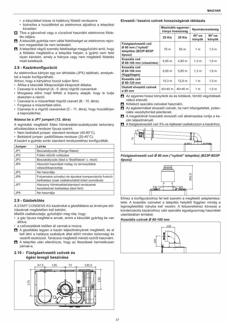
37
MAGYAR
• a készüléket kösse rá hatékony földelő rendszerre• biztosítsa a hozzáférést az elektromos aljzathoz a telepítést
követően 0 Tilos a gázcsövet vagy a vízcsövet használni elektromos földe-
lés céljára. 9 A készülék gyártója nem vállal felelősséget az elektromos rajzo-
kon megadottak be nem tartásáért. 9 A telepítést végző személy felelőssége meggyőződni arról, hogy
a földelés megfelelő-e a telepítés helyén; a gyártó nem felel olyan károkért, amely a hiányos vagy nem megfelelő földelés miatt keletkezik.
2.8 - KazánkonfigurációAz elektronikus kártyán egy sor áthidalás (JPX) található, amelyek-kel a kazán konfigurálható.Ahhoz, hogy a kártyához hozzá tudjon férni:• Állítsa a készülék főkapcsolóját kikapcsolt állásba.• Csavarja ki a köpenyt (A - 9. ábra) rögzítő csavarokat.• Mozgassa előre majd felfelé a köpeny alapját, hogy le tudja
akasztani a vázról.• Csavarja ki a műszerfalat rögzítő csavart (B - 10. ábra).• Forgassa a műszerfalat előre.• Csavarja ki a rögzítő csavarokat (C - 11. ábra), hogy hozzáférjen
a kapocsléchez.
Iktassa be a JP7 jumpert (12. ábra)A leginkább megfelelő fűtési hőmérséklet-szabályozási tartomány előválasztása a rendszer típusa szerint.• Nem beiktatott jumper: standard rendszer (40-80°C).• Beiktatott jumper: padlófűtéses rendszer (20-45°C).A kazánt a gyártás során standard rendszerekhez konfigurálták.
Jumper LeírásJP1 Beszabályozás (Range Rated)JP2 Fűtési időzítő nullázásaJP3 Beszabályozás (lásd a “Beállítások” c. részt)JP4 Abszolút használati meleg víz termosztátok
választókapcsolójaJP5 Ne használjaJP6 Folyamatos szivattyú és éjszakai kompenzációs funkció
beiktatása (csak csatlakoztatott külső szondával)JP7 Alacsony hőmérséklet/standard rendszerek
kezelésének beiktatása (lásd fent)JP8 Ne használja
2.9 - GázbekötésA START CONDENS Kis kazánokat a gázellátásra az érvényes elő-írásoknak megfelelően kell bekötni.Mielőtt csatlakoztatja, győződjön meg róla, hogy:• a gáz típusa megfelel-e annak, amire a készülék gyárilag be van
állítva;• a csővezetékek kellően át vannak-e mosva.
9 A gázellátás legyen a kazán teljesítményének megfelelő, és el kell látni a hatályos szabályok által előírt minden biztonsági és vezérlő eszközzel. Tanácsos megfelelő méretű szűrőt használni.
9 A telepítés után ellenőrizze, hogy az illesztések hermetikusan zárnak-e.
2.10 - Füstgázelvezető csövek és égési levegő beszívása
67,5 135 72 130,5
130
175
Elvezető / beszívó csövek hosszúságának táblázata
Maximális egyenes irányú hosszúság Nyomásveszteség
25 Kis 29 Kis 45°-os könyök
90°-os könyök
Füstgázelvezető cső Ø 80 mm (“nyitott” telepítés) (B23P-B53P típusú)
70 m 65 m 1 m 1,5 m
Koaxális cső Ø 60-100 mm (vízszintes) 5,85 m 4,85 m 1,3 m 1,6 m
Koaxális cső Ø 60-100 mm (függőleges)
6,85 m 5,85 m 1,3 m 1,6 m
Koaxális cső Ø 80-125 mm 15,3 m 12,8 m 1 m 1,5 m
Osztott elvezető csövek ø 80 mm 45+45 m 40+40 m 1 m 1,5 m
9 Az egyenes hossz könyökök és és toldások, tömítő végződések nélkül értendő.
9 Kötelező speciális csöveket használni. 9 Az égésterméket elvezető csövek, ha nem hőszigeteltek, poten-
ciális veszélyforrást jelentenek. 9 A megadottnál hosszabb elvezető cső alkalmazása rontja a ka-
zán teljesítményét. 9 A füstgázelvezető cső 3%-os lejtéssel csatlakozzon a kazánhoz.
3°
Füstgázelvezető cső Ø 80 mm (“nyitott” telepítés) (B23P-B53P típusú)
262,
5
Ehhez a konfigurációhoz fel kell szerelni a megfelelő adapterkész-letet. A koaxiális csöveket a telepítés helyétől függően mindig a legmegfelelőbb irányba kell vezetni. A felszereléshez kövesse a kondenzációs kazánokhoz való speciális egységcsomag használati utasításában leírtakat.Koaxiális csövek Ø 60-100 mm
130
100
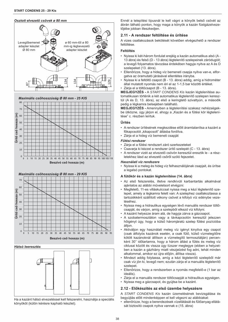
38
START CONDENS 25 - 29 Kis
Osztott elvezető csövek ø 80 mm
134
134
87 129
Levegőbemenet adapter készlet
Ø 80 mm
ø 60 mm-től ø 80 mm-ig légbevezető
adapter készlet
Maximális csőhosszúság Ø 80 mm - 25 KIS
0
10
20
30
40
50
60
70
80
0 5 10 15 20 25 30 35 40 45 50 55 60 65 70 75 80 85 90 95 100 105 110
Beszívó cső hossza (m)
Ürítő
cső
hoss
za (m
)
Maximális csőhosszúság Ø 80 mm - 29 KIS
0
10
20
30
40
50
60
70
0 5 10 15 20 25 30 35 40 45 50 55 60 65 70 75 80 85 90 95
Beszívó cső hossza (m)
Ürítő
cső
hoss
za (m
)
Hátsó leeresztés
Ha a kazánt hátsó elvezetéssel kell felszerelni, használja a speciális könyököt (külön kérésre kapható készlet).
Ennél a telepítési típusnál le kell vágni a könyök belső csövét az ábrán látható ponton, hogy maga a könyök a kazán füstgázelveze-tőjébe jobban illeszkedjen.
2.11 - A rendszer feltöltése és ürítéseA vizes csatlakozások bekötését követően elvégezhető a rendszer feltöltése.
Feltöltés• Nyissa ki két-három fordulat erejéig a kazán automatikus alsó (A -
13 ábra) és felső (D - 13 ábra) légtelenítő szelepeinek záródugóit; a levegő folyamatos távozása érdekében hagyja nyitva az A és D szelepeket (13. ábra).
• Ellenőrizze, hogy a hideg víz bemeneti csapja nyitva van-e, elfor-gatva az óramutató járásával ellentétes irányba.
• Nyissa ki a feltöltő csapot (B - 13. ábra) addig, amíg a hidrométer által mutatott nyomás nem éri el az 1-1,5 bar közötti értéket.
• Zárja el a töltőcsapot (B - 13. ábra).MEGJEGYZÉS - A START CONDENS Kis kazán légtelenítése au-tomatikusan történik a két automatikus légtelenítő szelepen keresz-tül (A és D, 13. ábra), az első a keringtető szivattyún, a második pedig a légkamra belsejében található.MEGJEGYZÉS - Amennyiben a légtelenítési szakasz nehézségek-be ütközne, úgy járjon el, ahogy a „Kazán és a fűtési kör légtelení-tése” c. részben leírtuk.
Ürítés• A rendszer ürítésének megkezdése előtt áramtalanítsa a kazánt a
főkapcsolót „kikapcsolt” állásba fordítva.• Zárja el a hideg víz bemeneti csapjátFűtési rendszer• Zárja el a fűtési rendszert záró szerkezeteket• Csavarja ki kézzel a rendszer ürítő szelepét (C - 13. ábra)• A rendszer vizét az elvezető csövön keresztül eresztik le - a rész-
letekhez lásd az elvezető csőről szóló fejezetet.Használati víz rendszere• Nyissa ki a meleg és hideg víz felhasználójának csapjait, és ürítse
a legalsó pontokat.
A fűtőkör és a kazán légtelenítése (14. ábra)• Az első felszerelés, illetve rendkívüli karbantartás alkalmával
ajánlatos az alábbi műveletsort elvégzni:• Megfelelő, 11-es villáskulccsal nyissa meg a kézi légtelenítő sze-
lepet, amely a légkamra felett van: A szelephez csatlakoztassa a tartozékként szállított vékony csövet a kifolyó víz edénybe veze-téséhez.
• Nyissa meg a hidraulikus egységen lévő manuális rendszer töltő-csapját, és várjon, amíg a szelepből elkezd víz kifolyni.
• A kazánt helyezze áram alá, de hagyja zárva a gázcsapot.• A szobatermosztáton vagy a távkapcsolón keresztül jelezzen
hőigényt úgy, hogy a külső háromjáratú szelep fűtési pozícióba álljon.
• Aktiváljon egy használati meleg víz igényt kinyitva egy csapot (csak átfolyós kazánok esetén, a csak fűtő, külső vízmelegítőre kötött kazánoknál állítson a vízmelegítő termosztátján) percen-ként 30’’ időtartamra, hogy a három állást a fűtés és meleg víz ciklusai között és vissza úgy tízszer megtegye (ebben a helyzet-ben a kazán a gázhiány miatt vészjelzést fog adni, tehát minden alkalommal, amikor ez újra előjön, állítsa vissza).
• Mindezt addig folytassa, amíg a kézi légtelenítő szelepből már csak víz jön ki, levegő nem; ezután zárja el a manuális légtelenítő szelepet.
• Ellenőrizze, hogy a rendszerben a nyomás megfelelő-e (1 bar az ideális).
• Zárja el a manuális rendszer töltőcsapját a hidraulikus egységen.• Nyissa meg a gázcsapot, és gyújtsa be a kazánt.
2.12 - Előkészítés az első üzembe helyezésreA START CONDENS Kis kazán üzemelésének bevizsgálása és begyújtás előtt mindenképpen el kell végezni az alábbiakat:• ellenőrizze, hogy a berendezések vízellátását és fűtőanyag ellátá-
sát biztosító csapok nyitva vannak e (15. ábra)
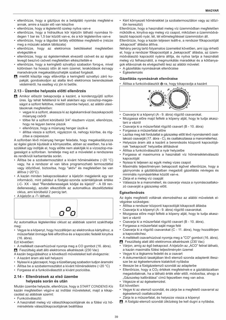
39
MAGYAR
• ellenőrizze, hogy a gáztípus és a betápláló nyomás megfelel-e annak, amire a kazán elő van készítve
• ellenőrizze, hogy a légtelenítő szelep nyitva van-e• ellenőrizze, hogy a hidraulikus kör kijelzőn látható nyomása hi-
degen 1 bar és 1,5 bar között van-e, és a kör légtelenítve van-e• ellenőrizze, hogy a tágulási tartály előtöltése megfelelő-e (nézze
meg a műszaki adatok táblázata)• ellenőrizze, hogy az elektromos bekötéseket megfelelően
elvégezték-e• ellenőrizze, hogy az égéstermékek elvezető csöveit és az égési
levegő beszívó csöveit megfelelően elkészítették-e• ellenőrizze, hogy a keringtető szivattyú szabadon forog-e, mivel
különösen ha hosszú időn át nem üzemel, lerakódások és/vagy maradványok megakadályozhatják szabad forgását. 9 mielőtt kilazítja vagy eltávolítja a keringtető szivattyú záró ku-
pakját, gondoskodjon az alatta lévő elektromos berendezések védelméről, ha esetleg víz jön ki belőle.
2.13 - Üzembe helyezés előtti ellenőrzés 9 Amikor először bekapcsolja a kazánt, a kondenzgyűjtő szifon
üres. Így tehát feltétlenül ki kell alakítani egy vízoszlop-magas-ságot a szifont feltöltve, mielőtt üzembe helyezi, az alábbi utasí-tásoknak megfelelően:• vegye ki a szifont, akassza ki az égéskamrával összekapcsoló
műanyag csőről• töltse fel a szifont körülbelül 3/4” részbern vízzel, ellenőrizze,
hogy ne legyen benne piszok• ellenőrizze, hogy a műanyag henger úszik-e• állítsa vissza a szifont, vigyázzon rá, nehogy kiürítse, és rög-
zítse a csipesszel.A szifonban lévő műanyag henger feladata, hogy megakadályozza az égési gázok kijutását a környezetbe, abban az esetben, ha a ké-szüléket úgy indítják el, hogy előtte nem alakítják ki a vízoszlop-ma-gasságot a szifonban. Ismételje meg ezt a műveletet a rendszeres és rendkívüli karbantartás során.• Állítsa be a szobatermosztátot a kívánt hőmérsékletre (~20 °C)
vagy, ha a rendszer el van látva programozható termosztáttal vagy időzítővel, biztosítsa, hogy "aktív" és megfelelően be van állítva (~20°C).
• A kazán minden bekapcsolásakor a kijelzőn megjelenik egy sor információ, mint például a füstgáz-szonda számlálójának értéke (-C- XX - lásd "Rendellenességek kódjai és kijelző" - A 09 ren-dellenesség), azután elkezdődik az automatikus átszellőztetési ciklus, ami körülbelül 2 percig tart.
• A kijelzőn a látható.
Az automatikus légtelenítési ciklust az alábbiak szerint szakíthatja meg:• Vegye le a köpenyt, hogy hozzáférjen az elektronikus kártyához, a
műszerfalat önmaga felé elfordítva és a kapocsléc fedelét kinyitva (16. ábra).
Ezt követően:• A mellékelt csavarhúzóval nyomja meg a CO gombot (16. ábra).
9 Feszültség alatt álló elektromos alkatrészek (230 Vac)A kazán begyújtásához a következő műveleteket kell elvégeznie:• A kazánt áram alá kell helyezni• Nyissa ki a gázcsapot, hogy a tűzelőanyag szabadon tudjon áramolni• Állítsa be a szobatermosztátot a kívánt hőmérsékletre (~20 °C)• Forgassa el a funkcióválasztót a kívánt pozícióba.
2.14 - Ellenőrzések az első üzembe helyezés során és után
Miután üzembe helyezte, ellenőrizze, hogy a START CONDENS Kis kazán megfelelően végzi-e az indítási műveleteket, majd a kikap-csolást az alábbiak szerint:• Funkcióválasztó:• A használati meleg víz választókapcsolójának és a fűtési víz hő-
mérséklete választókapcsolójának beállítása
• Kért környezeti hőmérséklet (a szobatermosztáton vagy az időzí-tőn keresztül)
Ellenőrizze, hogy a használati meleg víz üzemmódban megfelelően működik-e, kinyitva egy meleg víz csapot, miközben a üzemmódvá-lasztó kapcsoló nyár, tél, tél előmelegítéssel üzemmódon áll.Ellenőrizze, hogy a kazán teljesen leállt-e, a rendszer főkapcsolóját „kikapcsolt” állásba állítva.Néhány percig tartó folyamatos üzemelést követően, ami úgy érhető el, hogy a rendszer főkapcsolóját a „bekapcsolt” állásba, az üzem-módválasztó kapcsolót nyárra állítja, és nyitva tartja a használati meleg víz felhasználót, a megmunkálás maradékai és a kötőanya-gok eltávoznak és elvégezhető lesz az alábbi művelet:• A gázellátás nyomásának ellenőrzése• Égéselemzés
Gázellátás nyomásának ellenőrzése• Állítsa a funkcióválasztót -ra, hogy kikapcsolja a kazánt
• Csavarja ki a köpenyt (A - 9. ábra) rögzítő csavarokat.• Mozgassa előre majd felfelé a köpeny alját, hogy le tudja akasz-
tani a vázról• Csavarja ki a műszerfalat rögzítő csavart (B - 10. ábra)• Forgassa a műszerfalat előre• Lazítsa meg két fordulattal a gázszelep előtt lévő nyomásmérő csat-
lakozó csavarját (17. ábra - C), és csatlakoztassa a manométerhez.• Helyezze áram alá a kazánt a berendezés központi kapcsolójá-
nak “bekapcsolt” helyzetbe állításával• Állítsa a funkcióválasztót a nyár helyzetbe• Forgassa el maximumra a használati víz hőmérsékletválasztó
kapcsolóját• Nyissa ki teljesen az egyik meleg vizes csapot• Maximális teljesítményen bekapcsolt égővel ellenőrizze, hogy a
gáznyomás a gáztáblázatban megadott gázellátás névleges és minimális nyomásértékei között van-e.
• Zárja el a meleg víz csapját• Válassza le a manométert, és csavarja vissza a nyomáscsatlako-
zó csavarját a gázszelep előtt.
ÉgésellenőrzésAz égés megfelelő voltának elemzéséhez az alábbi műveletek el-végzése szükséges:• Állítsa a rendszer központi kapcsolóját kikapcsolt állásba• Csavarja ki a köpenyt (A - 9. ábra) rögzítő csavarokat.• Mozgassa előre majd felfelé a köpeny alját, hogy le tudja akasz-
tani a vázról• Csavarja ki a műszerfalat rögzítő csavart (B - 10. ábra).• Forgassa a műszerfalat saját maga felé• Csavarja ki a rögzítő csavarokat (C - 11. ábra), hogy hozzáférjen
a kapocsléchez.• A mellékelt csavarhúzóval nyomja meg a "CO" gombot (16. ábra).
9 Feszültség alatt álló elektromos alkatrészek (230 Vac)• Várjon, amíg az égő bekapcsol. A kijelzőn az „ACO” felirat látható,
a kazán maximális fűtési teljesítményén üzemel• Vegye ki a légkamra fedelét és a csavart• A dokumentáció tasakjában lévő elemző szonda adapterét illesz-
sze be az égéselemzésre kialakított nyílásba• Illessze be a füstgázelemző szondát az adapterbe• Ellenőrizze, hogy a CO2 értékek megfelelnek-e a gáztáblázatban
megadottaknak, ha a látható érték eltér ettől, módosítsa, ahogy a „Gázszelep kalibrálása” című fejezetben meg van adva.
• Végezze el az égéselemzést.Ezt követően:• Vegye ki az elemző szondát, és zárja be a megfelelő csavarral az
égéselemző csatlakozókat• Zárja le a műszerfalat, és helyezze vissza a köpenyt
9 A füstgáz-elemző szondát ütközésig be kell dugni a nyílásba.

40
START CONDENS 25 - 29 Kis
9 Az égéselemző funkció működése közben is érvényben marad és működik az a funkció, amelyik leállítja a kazánt, ha a fűtővíz hőmérséklete eléri a határértéket, a kb. 90 °C-ot.
A beállítások elvégzése után:• Forgassa el a funkcióválasztót a kívánt üzemmódnak megfelelően• Állítsa be a választókapcsolókat (2 és 3) az ügyfél igényeinek
megfelelően. 9 A START CONDENS Kis kazán szállításakor metángázzal (G20)
történő üzemelésre van beállítva, amint ezt a műszaki adatok tartalmazó táblácska tanúsítja, tehát nincs szükség kalibrálásra.
9 Minden ellenőrzést kizárólag szakszerviz végezhet.
2.15 - Hőszabályozás beállításaA hőszabályozás csak csatlakoztatott külső szondával üzemel, ezért ha már telepítette, csatlakoztassa a külső szondát - külön kérés-re kapható tartozék - a kazán kapocslécén kialakított erre szolgáló csatlakozókra. Így beiktatja a HŐSZABÁLYOZÁS funkciót.
A kompenzációs görbe kiválasztásaA kompenzációs fűtési görbe gondoskodik az elméleti 20°C-os kör-nyezeti hőmérsékletről, ha a külső hőmérséklet +20°C és -20°C között van. A görbe kiválasztása a tervezett külső hőmérsékleti mi-nimumtól (vagyis földrajzilag más és más értéktől), valamint a ter-vezett előremenő hőmérséklettől (az adott fűtési rendszertől) függ. Ezt a telepítőnek kell körültekintően kiszámolnia az alábbi képletet alkalmazva:
KT=Tervezett előremenő hőmérséklet - Tshift
20 – tervezett minimális külső hőmérséklet
Tshift =30°C standard rendszerek25°C padlófűtéses rendszerekHa e számítás eredményeként olyan számot kapunk, amely két gör-be értéke közé esik, tanácsos azt a kompenzációs görbét választa-ni, amely közelebb áll a kapott értékhez.Példa a számításra: ha a számítással kapott érték 1,3, ez a 1 és 1,5 görbék között van. Válassza ki a legközelebbi görbét, tehát az 1.5-öt. A KT kiválasztását a kártyán található P3 trimmer segítségével kell elvégezni (lásd: többvonalas kapcsolási rajz).Ahhoz, hogy a P3-hoz hozzá tudjon férni:• Vegye le a köpenyt,• Csavarja ki a műszerfalat rögzítő csavart• Forgassa a műszerfalat saját maga felé• Csavarja ki a kapocsléc fedélrögzítő csavarjait• Akassza ki a kártya fedelét
9 Feszültség alatt álló elektromos alkatrészek (230 Vac)Az alábbi KT értékeket lehet beállítani:• standard rendszer: 1,0-1,5-2,0-2,5-3,0• padlófűtéses rendszer 0,2-0,4-0,6-0,8• és a kijelzőn láthatóak körülbelül 3 mp-ig, miután elforgatta a P3
trimmert.
Hőigény típusa
Ha a kazán szobatermosztátra van kötve (JUMPER 6 nincs beiktatva)A hőigényt ez esetben a szobatermosztát érintkezőjének záródá-sa okozza, az érintkező kinyílása pedig utasít a kikapcsolásra. Az előremenő hőmérsékletet a kazán automatikusan számítja ki, a felhasználó azonban állíthat a kazánon. Az interfészen keresztül a FŰTÉS paramétereinek módosításakor nem a FŰTÉSI SET POINT értéket állíthat be, hanem egy 15 °C és 25 °C közötti értéket. Ennek kiválasztása nem módosítja közvetlenül az előremenő hőmérsékle-tet, de szerepel abban a számításban, amit a kazán végez az érték automatikus meghatározásához, és ennyivel módosítja a referencia hőfokot (0 = 20 °C).Ha a kazánra rá van kapcsolva egy időprogramozó (JUMPER JP6 beiktatva)Az érintkezők zárásakor a hőigényt az előremenő hőmérséklet-ér-zékelője adja, mégpedig a külső hőmérséklethez szabottan ahhoz, hogy a fűtött helyiségben a megadott NAPPALI hőmérsékleti érték (20 °C) alakuljon ki. A pólusok nyitása nem eredményez azonnal kikapcsolást, hanem csupán a klimatikus görbe lecsökkentését (pár-huzamos eltolását) az ÉJSZAKAI szintre (16 °C). Így aktiválja az
éjszakai funkciót. Az előremenő hőmérsékletet a kazán automatiku-san számítja ki, a felhasználó azonban állíthat a kazánon.Az interfészen keresztül a FŰTÉS paramétereinek módosításakor nem a FŰTÉSI SET POINT értéket állíthat be, hanem egy 15 °C és 25 °C közötti értéket. Ennek kiválasztása nem módosítja közvetle-nül az előremenő hőmérsékletet, de szerepel abban a számításban, amit a kazán végez az előremenő hőmérséklet automatikus megha-tározásához, és ennyivel módosítja felfelé vagy lefelé a referencia hőfokot (0 = 20 °C a NAPPALI; 16 °C az ÉJSZAKAI szinthez).Korábbi tapasztalatai alapján a telepítő kiválaszthat más görbéket is.
Hőszabályozási görbékA kijelző a görbe értékét 10-zel megszorozva mutatja (pl. 3,0 = 30)
Temperatura esterna (˚C)
Tem
pera
tura
di
man
data
(˚C
)
20
30
40
50
60
70
80
90
100
-20
0,2
0,4
0,6
0,8
1,0
1,5
2,02,53,0
T80
T45
-15-10-505101520
Külső hőmérséklet (°C)Előr
emenő
hőm
érsé
klet
(°C
)T80 - std rendszer fűtési setpoint maximális hőmérséklet (1. poz. jumper nincs beillesztve)T45 - padlófűtéses rendszerek fűtési set point maximális hő-mérséklet (a jumper 1. poz. be van iktatva)
Klimatikus görbe korrekciója
20 °C25 ° C
15 °C
10
20
30
40
50
60
70
80
90
-20-15-10-5051015202530
Külső hőmérséklet (°C)
Előr
emenő
hőm
érsé
klet
(°C
)
Éjszakai párhuzamos csökkentés
10
20
30
40
50
60
70
80
90
-20-15-10-505101520Temperatura Esterna
Tem
per
atu
ra d
i
Curva climatica GIORNO
Curva climatica NOTTE
16 °C20 °C
Külső hőmérséklet (°C)
Éjszakai klímagörbe
Nappali klímagörbe
Előr
emenő
hőm
érsé
klet
(°C
)
3 - BeállításokA START CONDENS Kis kazán szállításakor metángázzal (G20) tör-ténő üzemelésre van beállítva, és a gyárban úgy vannak beszabá-lyozva, amint ezt a műszaki adatok tartalmazó táblácska tanúsítja.
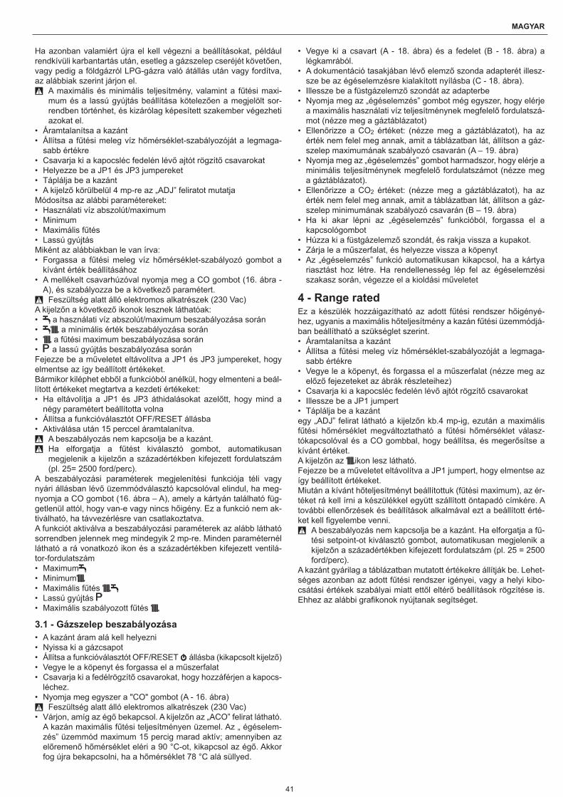
41
MAGYAR
Ha azonban valamiért újra el kell végezni a beállításokat, például rendkívüli karbantartás után, esetleg a gázszelep cseréjét követően, vagy pedig a földgázról LPG-gázra való átállás után vagy fordítva, az alábbiak szerint járjon el.
9 A maximális és minimális teljesítmény, valamint a fűtési maxi-mum és a lassú gyújtás beállítása kötelezően a megjelölt sor-rendben történhet, és kizárólag képesített szakember végezheti azokat el.
• Áramtalanítsa a kazánt• Állítsa a fűtési meleg víz hőmérséklet-szabályozóját a legmaga-
sabb értékre• Csavarja ki a kapocsléc fedelén lévő ajtót rögzítő csavarokat• Helyezze be a JP1 és JP3 jumpereket• Táplálja be a kazánt• A kijelző körülbelül 4 mp-re az „ADJ” feliratot mutatjaMódosítsa az alábbi paramétereket:• Használati víz abszolút/maximum• Minimum• Maximális fűtés• Lassú gyújtásMiként az alábbiakban le van írva:• Forgassa a fűtési meleg víz hőmérséklet-szabályozó gombot a
kívánt érték beállításához• A mellékelt csavarhúzóval nyomja meg a CO gombot (16. ábra -
A), és szabályozza be a következő paramétert. 9 Feszültség alatt álló elektromos alkatrészek (230 Vac)
A kijelzőn a következő ikonok lesznek láthatóak:• a használati víz abszolút/maximum beszabályozása során• a minimális érték beszabályozása során• a fűtési maximum beszabályozása során• a lassú gyújtás beszabályozása soránFejezze be a műveletet eltávolítva a JP1 és JP3 jumpereket, hogy elmentse az így beállított értékeket.Bármikor kiléphet ebből a funkcióból anélkül, hogy elmenteni a beál-lított értékeket megtartva a kezdeti értékeket:• Ha eltávolítja a JP1 és JP3 áthidalásokat azelőtt, hogy mind a
négy paramétert beállította volna• Állítsa a funkcióválasztót OFF/RESET állásba• Aktiválása után 15 perccel áramtalanítva.
9 A beszabályozás nem kapcsolja be a kazánt. 9 Ha elforgatja a fűtést kiválasztó gombot, automatikusan
megjelenik a kijelzőn a századértékben kifejezett fordulatszám (pl. 25= 2500 ford/perc).
A beszabályozási paraméterek megjelenítési funkciója téli vagy nyári állásban lévő üzemmódválasztó kapcsolóval elindul, ha meg-nyomja a CO gombot (16. ábra – A), amely a kártyán található füg-getlenül attól, hogy van-e vagy nincs hőigény. Ez a funkció nem ak-tiválható, ha távvezérlésre van csatlakoztatva.A funkciót aktiválva a beszabályozási paraméterek az alább látható sorrendben jelennek meg mindegyik 2 mp-re. Minden paraméternél látható a rá vonatkozó ikon és a századértékben kifejezett ventilá-tor-fordulatszám• Maximum• Minimum• Maximális fűtés • Lassú gyújtás • Maximális szabályozott fűtés
3.1 - Gázszelep beszabályozása• A kazánt áram alá kell helyezni• Nyissa ki a gázcsapot• Állítsa a funkcióválasztót OFF/RESET állásba (kikapcsolt kijelző)• Vegye le a köpenyt és forgassa el a műszerfalat• Csavarja ki a fedélrögzítő csavarokat, hogy hozzáférjen a kapocs-
léchez.• Nyomja meg egyszer a "CO" gombot (A - 16. ábra)
9 Feszültség alatt álló elektromos alkatrészek (230 Vac)• Várjon, amíg az égő bekapcsol. A kijelzőn az „ACO” felirat látható.
A kazán maximális fűtési teljesítményen üzemel. Az „ égéselem-zés” üzemmód maximum 15 percig marad aktív; amennyiben az előremenő hőmérséklet eléri a 90 °C-ot, kikapcsol az égő. Akkor fog újra bekapcsolni, ha a hőmérséklet 78 °C alá süllyed.
• Vegye ki a csavart (A - 18. ábra) és a fedelet (B - 18. ábra) a légkamrából.
• A dokumentáció tasakjában lévő elemző szonda adapterét illesz-sze be az égéselemzésre kialakított nyílásba (C - 18. ábra).
• Illessze be a füstgázelemző szondát az adapterbe• Nyomja meg az „égéselemzés” gombot még egyszer, hogy elérje
a maximális használati víz teljesítménynek megfelelő fordulatszá-mot (nézze meg a gáztáblázatot)
• Ellenőrizze a CO2 értéket: (nézze meg a gáztáblázatot), ha az érték nem felel meg annak, amit a táblázatban lát, állítson a gáz-szelep maximumának szabályozó csavarán (A – 19. ábra)
• Nyomja meg az „égéselemzés” gombot harmadszor, hogy elérje a minimális teljesítménynek megfelelő fordulatszámot (nézze meg a gáztáblázatot).
• Ellenőrizze a CO2 értéket: (nézze meg a gáztáblázatot), ha az érték nem felel meg annak, amit a táblázatban lát, állítson a gáz-szelep minimumának szabályozó csavarán (B – 19. ábra)
• Ha ki akar lépni az „égéselemzés” funkcióból, forgassa el a kapcsológombot
• Húzza ki a füstgázelemző szondát, és rakja vissza a kupakot.• Zárja le a műszerfalat, és helyezze vissza a köpenyt• Az „égéselemzés” funkció automatikusan kikapcsol, ha a kártya
riasztást hoz létre. Ha rendellenesség lép fel az égéselemzési szakasz során, végezze el a kioldási műveletet
4 - Range ratedEz a készülék hozzáigazítható az adott fűtési rendszer hőigényé-hez, ugyanis a maximális hőteljesítmény a kazán fűtési üzemmódjá-ban beállítható a szükséglet szerint.• Áramtalanítsa a kazánt• Állítsa a fűtési meleg víz hőmérséklet-szabályozóját a legmaga-
sabb értékre• Vegye le a köpenyt, és forgassa el a műszerfalat (nézze meg az
előző fejezeteket az ábrák részleteihez)• Csavarja ki a kapocsléc fedelén lévő ajtót rögzítő csavarokat• Illessze be a JP1 jumpert• Táplálja be a kazántegy „ADJ” felirat látható a kijelzőn kb.4 mp-ig, ezután a maximális fűtési hőmérséklet megváltoztatható a fűtési hőmérséklet válasz-tókapcsolóval és a CO gombbal, hogy beállítsa, és megerősítse a kívánt értéket.A kijelzőn az ikon lesz látható.Fejezze be a műveletet eltávolítva a JP1 jumpert, hogy elmentse az így beállított értékeket.Miután a kívánt hőteljesítményt beállítottuk (fűtési maximum), az ér-téket rá kell írni a készülékkel együtt szállított öntapadó címkére. A további ellenőrzések és beállítások alkalmával ezt a beállított érté-ket kell figyelembe venni.
9 A beszabályozás nem kapcsolja be a kazánt. Ha elforgatja a fű-tési setpoint-ot kiválasztó gombot, automatikusan megjelenik a kijelzőn a századértékben kifejezett fordulatszám (pl. 25 = 2500 ford/perc).
A kazánt gyárilag a táblázatban mutatott értékekre állítják be. Lehet-séges azonban az adott fűtési rendszer igényei, vagy a helyi kibo-csátási értékek szabályai miatt ettől eltérő beállítások rögzítése is. Ehhez az alábbi grafikonok nyújtanak segítséget.

42
START CONDENS 25 - 29 Kis
Start Condens 25 Kis
Kibocsátás - hőteljesítmény-görbe (MTN)
0102030405060708090100110120130140150160170180190200
4 6 8 10 12 14 16 18 20 22 24 26
Hőteljesítmény (kW)
CO
kib
ocsá
tás
s.a.
(p.p
.m.)
G20
Hőteljesítmény-görbe – ventilátor fordulatszáma (MTN)
12001600200024002800320036004000440048005200560060006400
4 6 8 10 12 14 16 18 20 22 24 26
Hőteljesítmény (kW)
CO
kib
ocsá
tás
s.a.
(p.p
.m.)
G20
Start Condens 29 Kis
Kibocsátás - hőteljesítmény-görbe (MTN)
0102030405060708090100110120130140150160170180190200
4 6 8 10 12 14 16 18 20 22 24 26 28 30
Hőteljesítmény (kW)
CO
kib
ocsá
tás
s.a.
(p.p
.m.)
G20
Hőteljesítmény-görbe – ventilátor fordulatszáma (MTN)
12001600200024002800320036004000440048005200560060006400
4 6 8 10 12 14 16 18 20 22 24 26 28 30
CO
kib
ocsá
tás
s.a.
(p.p
.m.)
G20
Hőteljesítmény (kW)
5 - Átalakítás az egyik gáztípusról a másikraA kazán szállításakor metángázzal (G20) történő üzemelésre van beállítva, amint ezt a műszaki adatok tartalmazó táblácska tanúsítja.Lehetőség van a kazán gáztípusának átállítására, a kifejezetten erre a célra készült készletek segítségével.• metángáz átalakító készlet
• LPG gáz átalakító készlet 9 Az átállítást csak r szakszervíz végezheti el, vagy pedig a r által erre feljogosított személy a már telepített kazánon is.
9 A felszereléshez nézze meg a készlethez mellékelt utasításokat. 9 Az átalakítás után állítsa be ismét a kazánt, követve az erre vo-
natkozó rész utasításait, majd helyezze fel a kazánra a készlet-ben található új azonosító fémtáblát.
Ha szükségessé válik, hogy az egyik gázfajtáról áttérjen egy má-sikra, a művelet könnyen elvégezhető már telepített kazánoknál is.A műveletet azonban csakis képesített szakember végezheti el.A kazán szállításakor metángázzal (G20) történő üzemelésre van beállítva, amint ezt a címkéje is tanúsítja.Megvan azonban a lehetőség, hogy propángázzal történő üzemelés-re állítsák át a készüléket az e célra szolgáló készlet segítségével.A leszereléshez kövesse az alábbi használati utasítást:• Áramtalanítsa a kazánt, és zárja el a gázcsapot• Vegye le ezeket a következő sorrendben: köpeny és légkamra
fedele• Vegye ki a műszerfalat rögzítő csavart• Forgassa a műszerfalat előre• Vegye le a gázszelepet (A - 20. ábra)• Vegye ki a (B - 20. ábra) fúvókát, és tegye be helyette a pótalkat-
részként szállított másik fúvókát• Szerelje vissza a gázszelepet• Húzza ki a zajcsökkentőt a keverő egységből• Nyissa ki a két felét a megfelelő akasztókat megfogva• A 25 KIS típusokhoz: cserélje ki a levegő diafragmáját (C - 21.
ábra), amely a zajcsökkentőben van• A 29 KIS típusokhoz: illessze be a levegő diafragmáját (C - 21.
ábra), amely a zajcsökkentőben van• Szerelje vissza a légkamra fedelét• Helyezze újra áram alá a kazánt, és nyissa ki a gázcsapot.Állítsa be a kazánt annak megfelelően, ami a „Beállítások” című fe-jezetben le van írva, nézze meg a LPG-re vonatkozó adatokat.
9 Az átalakítást csakis erre képesítéssel rendelkező szakember végezheti.
9 Az átalakítás után helyezze fel a kazánra a készletben található új azonosító fémtáblát.
6 - Üzembe helyezés 9 A kazán első üzembe helyezését szakember végezze el.
A kazán minden bekapcsoláskor megjelenik a kijelzőn egy sor infor-máció, ezt követően automatikus légtelenítési ciklust végez mintegy 2 percnyi időtartamon át.A kijelzőn a jelzés látható .Állítsa a funkcióválasztót a kívánt pozícióba.
6.1 - TélA funkcióválasztót a beállítási tartományon belül elforgatva a kazán fűtésre és meleg víz előállítására áll be. Hőigény esetén a kazán bekapcsol. A digitális kijelző jelzi a fűtési víz hőmérsékletét. Hasz-nálati meleg víz igény esetén a kazán bekapcsol. A kijelző jelzi a használati meleg víz hőmérsékletét.
Fűtővíz hőmérsékletének beállításaA fűtővíz hőmérsékletének beállításához forgassa el az üzemmód-választó kapcsolót a beállítási tartományon belül (az óramutató járá-sával megegyező irányban, hogy megnövelje az értéket, az óramu-tató járásával ellentétes irányba, hogy lecsökkentse).A rendszer típusa szerint előzetesen kiválasztható a megfelelő hő-mérséklettartomány:• standard rendszerek 40-80°C• padlófűtéses rendszerek 20-45°C.A részletekhez lásd a „Kazán konfigurációja” című fejezetet.

43
MAGYAR
A fűtési víz hőmérséklete
Használati meleg víz hőmérséklete
Fűtővíz hőmérsékletének beállítása külső hőmérséklet-érzékelő csatlakoztatása eseténHa a készülékhez tartozik bekötött külső hőmérséklet-érzékelő, az előremenő vízhőmérsékletet a kazán automatikusan állítja be, méghozzá úgy, hogy a hőmérséklet állandóan és gyorsan igazod-jék a külső hőmérséklet változásához. Ha viszont módosítani akar a hőmérsékleten, tehát magasabb vagy alacsonyabb értékre kívánja állítani az elektronikus kártya által automatikusan kiszámított érték-hez képest, megteheti a fűtővíz hőmérsékletét beállító gombot el-forgatva: az óramutató járásával megegyező irányba a hőmérséklet korrekciós értéke növelhető, ellenkező irányba csökkenthető.A korrigálás -5 és +5 komfortfokozat között történhet, amelyek a di-gitális kijelzőn láthatóak, amikor elforgatja a gombot.
6.2 - NyárA funkcióválasztót a nyár szimbólumra forgatva, csak a hagyo-mányos használati meleg víz-funkció lép működésbe. Használati meleg víz igény esetén a kazán bekapcsol. A digitális kijelző jelzi a használati meleg víz hőmérsékletét.
6.3 - Előmelegítés (meleg víz gyorsabb előállítása)Elforgatva a használati meleg víz hőfokszabályozó gombját a “ ” jelre aktiválódik az előmelegítés funkció. Állítsa vissza a használati víz hőfokszabályzó gombját a kívánt állásba. Ez a funkció lehetővé teszi a használati meleg víz hőcserélőjében lévő meleg víz melegen tartását a használat során felmerülő várakozási idő lecsökkentése érdekében. Ha az előmelegítő funkció be van kapcsolva, a kijelző a
jelzést mutatja.
A kijelző az aktuális igénynek megfelelően a fűtési vagy a használati meleg víz előremenő hőmérsékletét jelzi. Az égő bekapcsolásakor, előmelegítési igény esetén a villogó “ ” jel jelenik meg a kijelzőn. Az előmelegítő funkció kikapcsolásához állítsa a használati víz hőfok-szabályozó gombját ismét a “ ” jelre. A jelzés kikapcsol. Állítsa vissza a használati víz hőfokszabályzó gombját a kívánt állásba.A funkció nem működik OFF állapotba állított kazán esetén: funkci-óválasztó kikapcsolt helyzetben (OFF)
6.4 - Használati meleg víz hőmérsékletének beállításaA használati víz hőmérsékletének beállításához (fürdők, zuhany, konyha stb.) forgassa el az üzemmódválasztó kapcsolót az óramu-tató járásával megegyező irányban, hogy megnövelje az értéket, az óramutató járásával ellentétes irányba, hogy lecsökkentse (min. ér-ték 37°C-max érték 60°C). A kazán addig van stand-by állapotban, amíg hőigény esetén a égő bekapcsol. A kazán a beállított hőmér-séklet eléréséig vagy a hőigény kielégítéséig üzemel, majd ismét “stand-by” állapotba kerül. Ideiglenes leállás esetén a digitális kijel-ző a tapasztalt hibakódot mutatja.
6.5 - Fűtési Hőmérséklet Vezérlő Funkció (C.T.R.)A fűtővíz hőmérséklet-szabályozóját a fehér kijelzőkkel kiemelt részre fordítva működésbe lép a C.T.R. önszabályozó rendszere: a szobatermosztáton beállított hőmérséklet és az elérési idő alapján a kazán automatikusan változtatja a fűtővíz hőmérsékletét, így a ka-zán működési ideje lecsökken, kényelmesebbé és energiatakaréko-sabbá téve a használatát.
6.6 - Feloldási funkcióAz üzemelés visszaállításához állítsa a kapcsolót kikapcsolt állásba, várjon 5-6 másodpercet, majd állítsa a funkcióválasztó gombot a kí-vánt állásba. Ezen a ponton a kazán automatikusan újra fog indulni.MEGJEGYZÉS -Ha a feloldási kísérletek nem indítják el a műkö-dést, kérje szakszerviz segítségét
6.7 - Időleges kikapcsolásRövidebb távollét, hétvége, rövid utazás esetén állítsa funkcióvá-lasztót "OFF" állásba.
9 Ilyen módon a készülék áramellátása és a gázellátás megma-rad, így a kazán védelmi funkciói is működnek:
• Fagymentesítés: amint a kazánban a vízhőmérséklet 5 °C alá csökken, a keringtető szivattyú bekapcsol, és ha szükséges, az égő is minimális hőteljesítménnyel, hogy visszamelegítse a vizet a biztonságos hőmérsékletre (35 °C). A fagymentesítési ciklus so-rán a digitális kijelzőn megjelenik a szimbólum.
• Keringtető szivattyú blokkolás-gátlása: minden 24 órában elin-dul egy üzemelési ciklus.
6.8 - Kikapcsolás hosszabb időszakraAmennyiben a START CONDENS Kis kazánt hosszabb ideig nem kívánja használni, az alábbi műveleteket végezzék el:• Állítsa a funkcióválasztót kikapcsolt helyzetbe (OFF)• Állítsa a készülék főkapcsolóját „kikapcsolt” állásba• Zárja el a fűtési és használati víz rendszerének üzemanyag- és
vízcsapját.
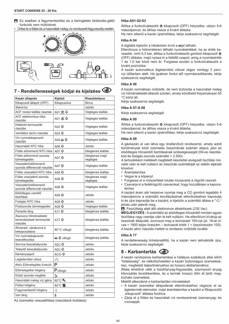
44
START CONDENS 25 - 29 Kis
9 Ez esetben a fagymentesítési és a keringtetés blokkolás-gátló funkciók nem működnek.
• Ürítse le a fűtési és a használati meleg víz rendszerét fagyveszély esetén.
7 - Rendellenességek kódjai és kijelzése Kazán állapota Kijelző RiasztástípusKikapcsolt állapot (OFF) Kikapcsolva NincsStand-by - JelzésACF modul leállás riasztás A01 Végleges leállásACF elektronikus hiba riasztás A01 Végleges leállás
Határoló termosztát riasztás A02 Végleges leállás
Ventilátor tacho riasztás A03 Végleges leállásVíz nyomáskapcsoló riasztás A04 Végleges leállás
Használati NTC hiba A06 JelzésFűtés előremenő NTC hiba A07 Ideiglenes leállásFűtés előremenő szonda túlmelegedés A07
Ideiglenes majd végleges
Visszatérő/előremenő szonda differenciál riasztás A07 Végleges leállás
Fűtés visszatérő NTC hiba A08 Ideiglenes leállásFűtés visszatérő szonda túlmelegedés A08
Ideiglenes majd végleges
Visszatérő/előremenő szonda differenciál riasztás A08 Végleges leállás
Elsődleges cserélő tisztítása A09 Jelzés
Füstgáz NTC hiba A09 JelzésFüstszonda túlmelegedés A09 Végleges leállásParazita láng A11 Ideiglenes leállásAlacsony hőmérsékletű berendezések termosztát riasztás
A77 Ideiglenes leállás
Átmeneti, várakozva a bekapcsolásra 80 °C villogó Ideiglenes leállás
Víz nyomáskapcsoló beavatkozása villogó Ideiglenes leállás
Service beszabályozás ADJ JelzésTelepítő beszabályozás ADJ JelzésKéményseprő ACO Jelzés
Légtelenítési ciklus Jelzés
Aktív Előmelegítés funkció Jelzés
Előmelegítési hőigény villogó Jelzés
Külső szonda megléte JelzésHasználati meleg víz igény 60°C JelzésFűtési hőigény 80°C JelzésFagymentesítő hőigény JelzésVan láng Jelzés
Az üzemelés visszaállítása (riasztások kioldása):
Hiba A01-02-03Állítsa a funkcióválasztót kikapcsolt (OFF) helyzetbe, várjon 5-6 másodpercet, és állítsa vissza a kívánt állásba.Ha nem sikerül a kazán újraindítása, kérje szakszerviz segítségét.
Hiba A 04A digitális kijelzőn a hibakódon kívül a jel látható.Ellenőrizze a hidrométeren látható nyomásértéket: ha az érték ke-vesebb, mint 0,3 bar, állítsa a funkcióválasztó gombot kikapcsolt (OFF) állásba, majd nyissa ki a feltöltő csapot, amíg a nyomásérték 1 és 1,5 bar közé nem ér. Forgassa ezután a funkcióválasztót a kívánt pozícióba:A kazán automatikus légtelenítési ciklust végez mintegy 2 perc-nyi időtartam alatt. Ha gyakran fordul elő nyomáscsökkenés, kérje szakszerviz segítségét.
Hiba A 06A kazán normálisan működik, de nem biztosítja a használati meleg víz hőmérsékletét állandó szinten, amely körülbelül folyamatosan 50 °C körül áll.Kérje szakszerviz segítségét.
Hiba A 07-A 08Kérje szakszerviz segítségét.
Hiba A 09Állítsa a funkcióválasztót kikapcsolt (OFF) helyzetbe, várjon 5-6 másodpercet, és állítsa vissza a kívánt állásba.Ha nem sikerül a kazán újraindítása, kérje szakszerviz segítségét.
Hiba A 09A gázkazán el van látva egy önellenőrző rendszerrel, amely adott körülmények közti üzemelés összóráinak számán alapul, jelzi az elsődleges hőcserélő tisztításának szükségességét (09-es riasztás-kód és füstgáz-szonda számláló > 2.500).A tartozékként mellékelt megfelelő készlettel elvégzett tisztítási mű-velet után le kell nullázni az összórák számlálóját az alábbi eljárást követve:• Áramtalanítsa• Vegye le a köpenyt• Forgassa el a műszerfalat miután kicsavarta a rögzítő csavart• Csavarja ki a fedélrögzítő csavarokat, hogy hozzáférjen a kapocs-
léchezA kazánt áram alá helyezve nyomja meg a CO gombot legalább 4 másodpercre a számláló lenullázásának ellenőrzéséhez kapcsolja ki és újra kapcsolja be a kazánt; a kijelzőn a számláló állása a "-C-” jelzés után jelenik meg.
9 Feszültség alatt álló elektromos alkatrészek (230 Vac)MEGJEGYZÉS - A számlálót az elsődleges hőcserélő minden egyes tisztítása vagy cseréje után le kell nullázni. Ha ellenőrizni kívánja az összórák állapotát, szorozza meg a leolvasást 100-zal (pl. 18-at ol-vas = 1800 teljes óraszám – leolvasott érték 1 = összóraszám 100).A kazán aktív riasztás mellett is rendesen működik tovább.
Hiba A 77A rendellenesség önhelyreállító, ha a kazán nem aktiválódik újra, kérje szakszerviz segítségét.
8 - Karbantartás A kazán rendszeres karbantartása a hatályos szabályok által előírt "kötelesség", és nélkülözhetetlen a kazán biztonságos üzemelésé-hez, megfelelő teljesítményéhez és hosszú élettartamához.Általa lehetővé válik a tüzelőanyag-fogyasztás, szennyező anyag kibocsátás lecsökkentése, és a termék hosszú időn át tartó meg-bízható üzemelése.Mielőtt elkezdené a karbantartási műveleteket:• A kazán üzemelési állapotának ellenőrzéséhez végezze el az
égéstermék-elemzést, majd áramtalanítsa a kazánt a főkapcsolót „kikapcsolt” állásba fordítva.
• Zárja el a fűtési és használati víz rendszerének üzemanyag- és vízcsapját.

45
MAGYAR
9 - Műszaki adatokLeírás Start Condens 25 Kis Start Condens 29 Kis
Tüzelőanyag G20 G31 G20 G31A készülék kategóriája II2H3PCélország HU
Készüléktípus B23P, B53P, C13-C13x, C23, C33-C33x, C43-C43x, C53-C53x, C83-C83x, C93-C93x
FűtésNominális hőteljesítmény kW 20,00 25,00Névleges hőteljesítmény (80/60°C) kW 19,50 24,45Névleges hőteljesítmény (50/30°C) kW 20,84 26,23Lecsökkent hőteljesítmény kW 5,00 6,00Redukált hőteljesítmény (80/60°C) kW 4,91 5,90Redukált hőteljesítmény (50/30°C) kW 5,36 6,40Range Rated nominális hőteljesítmény (Qn) kW 20,00 25,00Range Rated (Qm) minimális hőteljesítmény kW 5,00 6,00Használati vízNominális hőteljesítmény kW 25,00 29,00Névleges hőteljesítmény (*) kW 25,00 29,00Lecsökkent hőteljesítmény kW 5,00 6,00Redukált hőteljesítmény (*) kW 5,00 6,00HasznosHasznos hatásfok Pn max - Pn min (80/60°C) % 97,5 - 98,1 97,8 - 98,3Hasznos hatásfok 30% (visszatérő 47°C) % 102,2 102,0Hasznos hatásfok Pn max - Pn min (50/30°C) % 104,2 - 107,2 104,9 - 106,7Hasznos hatásfok 30% (visszatérő 30°C) % 108,9 108,4Hatásfok átlagos Pn Range Rated (80/60°C) % 97,8 98,0Hatásfok átlagos Pn Range Rated (50/30°C) % 106,0 106,1Égési hatásfok % 97,9 98,1Kazán maradék emelőnyomása csövek nélkül Pa 100 110Hozamok fűtésMaximális teljesítmény füstgáz tömegárama g/s 9,025 8,410 11,282 10,513Minimális teljesítmény füstgáz tömegárama g/s 2,140 2,103 2,568 2,523Levegő mennyisége Nm3/h 24,908 24,192 31,135 30,240Füstgáz mennyisége Nm3/h 26,914 24,267 33,642 31,209Maximális teljesítmény (λ) levegő többlet mutató % 1,304 1,311 1,304 1,311Minimális teljesítmény (λ) levegő többlet mutató % 1,235 1,311 1,235 1,311
9 A szükséges karbantartási műveleteket követően vissza kell ál-lítani az eredeti beállításokat, és el kell végezni az égéstermék-elemzést, hogy ellenőrizni lehessen a kazán helyes üzemelését.
9 A rendszeres és rendkívüli karbantartási műveleteket követően töltse fel a szifont az “Ellenőrzés az üzembe helyezést megelő-zően” c. fejezetben megadottaknak megfelelően.
8.1 - Kazán tisztításaMinden tisztítási művelet előtt áramtalanítsa a kazánt a főkapcsolót „kikapcsolt” állásba fordítva.
Külső tisztításTisztítsa meg a köpenyt, a kapcsolótáblát, a festett részeket és a műanyag részeket szappanos vizes ronggyal.Makacs szennyeződések esetén nedvesítse be a rongyot 50 %-os víz-denaturált szesz keverékkel vagy a célnak megfelelő speciális termékekkel.
0 Ne használjon üzemanyagot és/vagy maró oldatban vagy por alakú tisztítószerbe merített szivacsokat.
Belső tisztításA belső tisztítási műveletek megkezdését megelőzően:• Zárja el a gáz elzárócsapjait• Zárja el a rendszer csapjait.

46
START CONDENS 25 - 29 Kis
Leírás Start Condens 25 Kis Start Condens 29 Kis
Tüzelőanyag G20 G31 G20 G31
Hozamok HMV Maximális teljesítmény füstgáz tömegárama g/s 11,282 10,513 13,087 12,195Minimális teljesítmény füstgáz tömegárama g/s 2,140 2,103 2,568 2,523Levegő mennyisége Nm3/h 31,135 30,240 36,116 35,078Füstgáz mennyisége Nm3/h 33,642 31,209 39,025 36,203Maximális teljesítmény (λ) levegő többlet mutató % 1,304 1,311 1,304 1,311Minimális teljesítmény (λ) levegő többlet mutató % 1,235 1,311 1,235 1,311KibocsátásCO2 maximumon/minimumon % 9,0 - 9,5 10,5 - 10,5 9,0 - 9,5 10,5 - 10,5CO S.A. maximum/minimum kisebb mint ppm 180 - 20 190 - 20 160 - 20 250 - 25NOx S.A. maximum/minimum kisebb mint ppm 30 - 20 35 - 35 35 - 25 50 - 40Füstgáz-hőmérséklet (max/min teljesítmény) °C 65 - 58 62 - 55 63 - 58 62 - 56NOx osztály 5 5Központi fűtés működéseFűtés maximális üzemelési nyomás bar 3 3Minimális nyomás standard használat esetén bar 0,25 - 0,45 0,25 - 0,45Maximális engedélyezett hőmérséklet °C 90 90Kazán vízhőmérséklet kiválasztási tartomány °C 20/45 - 40/80 20/45 - 40/80Áramellátás Volt-Hz 230/50 230/50Tágulási tartály l 8 8Tágulási tartály előtöltése bar 1 1Eelektromos paraméterekFűtési teljes elektromos teljesítmény W 68 77Használati víz teljes elektromos teljesítmény W 82 89Keringtető szivattyú elektromos teljesítménye (1.000 l/h) W 39 39Elektromos védettségi fokozat IP X5D X5D
(*) Átlagérték különböző használati meleg víz üzemelési körülmények között
9.1 - Használati víz leírása
Leírás Start Condens 25 Kis Start Condens 29 KisMax. nyomás bar 6 6Min. nyomás bar 0,15 0,15Meleg víz mennyiség ∆t 25°C-on l/perc 14,3 16,6Meleg víz mennyiség ∆t 30°C-on l/perc 11,9 13,9Meleg víz mennyiség ∆t 35°C-on l/perc 10,2 11,9Használati vízhőmérséklet kiválasztási tartomány (± 3°C) °C 37 - 60 37 - 60HMV minimum hozama l/perc 2 2Áramlásszabályozó l/perc 10 12
9.2 - Gáztáblázat
Leírás Metángáz (G20) Propán (G31)Wobbe szám kisebb, mint (15 °C - 1013 mbar) MJ/m3S 45,67 70,69Fűtőérték kisebb mint MJ/m3S 34,02 88
Névleges tápnyomás mbarmm C.A.
25254,9 37
377,3
Min. tápnyomás mbarmm C.A.
10102,0
Start Condens 25 KisMembrán furatszáma n° 1 1Diafragma lyukátmérője Ø mm 4,8 3,8
Max. gázfogyasztás fűtés Sm3/hkg/h
2,12-
-1,55
Max. gázfogyasztás HMV Sm3/hkg/h
2,64-
-1,94
Min. gázfogyasztás fűtés Sm3/hkg/h
0,53-
-0,39
Min. gázfogyasztás HMV Sm3/hkg/h
0,53-
-0,39
Ventilátor fordulatszáma lassú gyújtáskor fordulat/perc 4.000 4.000Fűtés maximális ventilátor-fordulatszáma fordulat/perc 4.900 4.900Használati víz maximális ventilátor-fordulatszáma fordulat/perc 6.100 6.100Fűtés minimális ventilátor-fordulatszáma fordulat/perc 1.400 1.400Használati víz minimális ventilátor-fordulatszáma fordulat/perc 1.400 1.400

47
MAGYAR
Leírás Metángáz (G20) Propán (G31)
Start Condens 29 KisMembrán furatszáma n° 1 1Diafragma lyukátmérője Ø mm 5,1 3,9
Max. gázfogyasztás fűtés Sm3/hkg/h
2,64-
-1,94
Max. gázfogyasztás HMV Sm3/hkg/h
3,07-
-2,25
Min. gázfogyasztás fűtés Sm3/hkg/h
0,63-
-0,47
Min. gázfogyasztás HMV Sm3/hkg/h
0,63-
-0,47
Ventilátor fordulatszáma lassú gyújtáskor fordulat/perc 4.000 4.000Fűtés maximális ventilátor-fordulatszáma fordulat/perc 5.300 5.200Használati víz maximális ventilátor-fordulatszáma fordulat/perc 6.200 6.000Fűtés minimális ventilátor-fordulatszáma fordulat/perc 1.400 1.400Használati víz minimális ventilátor-fordulatszáma fordulat/perc 1.400 1.400
9.3 - ErP adatok táblázata
Paraméter Szimbólum Start Condens 25 Kis
Start Condens 29 Kis Egység
Környezeti fűtés szezonális energetikai hatékonysági osztály A AVízmelegítés energetikai hatékonysági osztály A ANévleges teljesítmény Pn 20 24 kWKörnyezeti fűtés szezonális energetikai hatékonysági osztály ηs 93 93 %Hasznos hőteljesítményA nominális hőteljesítményen és magas hőmérsékleten (*) P4 19,5 24,5 kWA nominális hőteljesítmény 30%-án és alacsony hőmérsékleten (**) P1 6,5 8,1 kWHatékonyságA nominális hőteljesítményen és magas hőmérsékleten (*) η4 88,1 88,2 %A nominális hőteljesítmény 30%-án és alacsony hőmérsékleten (**) η1 98,1 97,6 %Segéd áramfogyasztásTeljes terhelésnél elmax 29,0 38,0 WRészleges terhelésnél elmin 10,4 13,1 WStandby üzemmódban PSB 2,4 2,4 WEgyéb paraméterekStandby üzemmódban hőveszteség Pstby 40,0 35,0 WŐrláng energetikai fogyasztása Pign - - WÉves energetikai fogyasztás QHE 38 47 GJBeltéri hangteljesítmény szint LWA 50 55 dBNitrogénoxid kibocsátás NOx 19 23 mg/kWhHasználati meleg vízBejelentett terhelési profil XL XLNapi áramfogyasztás Qelec 0,183 0,197 kWhÉves áramfogyasztás AEC 40 43 kWhVízmelegítés energetikai hatékonysági osztály ηwh 85 84 %Napi tüzelőanyag fogyasztás Qfuel 22,920 23,021 kWhÉves tüzelőanyag fogyasztás AFC 17 17 GJ
(**) magas hőmérsékleten: 60°C visszatéréskor és 80°C a kazán előremenő részén(**) alacsony hőmérsékleten: visszatérő hőmérséklet 30°C.
MEGJEGYZÉSHivatkozással a 811/2013/EU felhatalmazáson alapuló rendeletre, a táblázatban megadott adatok használhatóak környezeti fűtőkészülékek, kevert fűtőkészülékek, környezeti fűtőkészülékek együttesei és hőmérsékletvezérlő eszközök és napelemes berendezések termékkártyáinak kitöltéséhez és címkézéséhez:A kazánra kapcsolt külső szonda
Alkatrész Osztály BónuszKülső szonda II 2%Kapcsolótábla V 3%Külső szonda + kapcsolótábla VI 4%
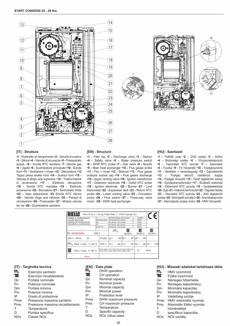
48
START CONDENS 25 - 29 Kis
[IT] - Targhetta tecnica Esercizio sanitario Esercizio riscaldamento
Qn Portata nominalePn Potenza nominale Qm Portata minimaPm Potenza minimaIP Grado di protezionePmw Pressione massima sanitarioPms Pressione massima riscaldamentoT TemperaturaD Portata specificaNOx Classe NOx
[EN] - Data plate DHW operation CH operation
Qn Nominal capacityPn Nominal powerQm Minimal capacityPm Minimal powerIP Protection levelPmw DHW maximum pressurePms CH maximum pressureT TemperatureD Specific capacityNOx NOx Value class
[HU] - Műszaki adatokat tartalmazó tábla HMV üzemmód Fűtési üzemmód
Qn Névleges hőterhelésPn Névleges teljesítményQm Minimális kapacitás Pm Minimális teljesítményIP Védettség szintjePmw HMV maximális nyomásPms Maximális fűtési nyomásT hőmérsékletD specifikus kapacitásNOx NOx osztály
[IT] - Struttura•1 - Rubinetto di riempimento •2 - Valvola di scarico •3 - Sifone •4 - Valvola di sicurezza •5 - Pressostato acqua •6 - Sonda NTC sanitario •7- Valvola gas •8 - Ugello •9 - Scambiatore principale •10 - Sonda fumi •11 - Ventilatore + mixer •12 - Silenziatore •13 Tappo presa analisi fumi •14 - Scarico fumi •15 - Valvola di sfogo aria superiore •16 - Trasformatore di accensione •17 - Elettrodo rilevazione •18 - Sonda NTC mandata •19 - Elettrodo accensione •20 - Bruciatore •21 - Termostato limite •22 - Vaso espansione •23 Sonda NTC ritorno •24 - Valvola sfogo aria inferiore •25 - Pompa di circolazione •26 - Flussostato •27 - Motore valvola tre vie •28 - Scambiatore sanitario
[EN] - Structure•1 - Filler tap •2 - Discharge valve •3 - Siphon •4 - Safety valve •5 - Water pressure switch •6 - DHW NTC probe •7 - Gas valve •8 - Nozzle •9 - Main heat exchanger •10 - Flue gases probe •11 - Fan + mixer •12 - Silencer •13 - Flue gases analysis socket cap •14 - Flue gases discharge •15 - Upper venting valve •16 - Ignition transformer •17 - Detection electrode •18 - Outlet NTC probe •19 - Ignition electrode •20 - Burner •21 - Limit thermostat •22 - Expansion tank •23 - Return NTC probe •24 - Lower venting valve •25 - Circulation pump •26 - Flow switch •27 - Three-way valve motor •28 - DHW heat exchanger
[HU] - Szerkezet•1 - Feltöltő csap •2 - Ürítő szelep •3 - Szifon •4 - Biztonsági szelep •5 - Víznyomáskapcsoló •6 - Használati NTC szonda •7 - Gázszelep •8 - Fúvóka •9 - Fő hőcserélő •10 - Füstgázszonda •11 - Ventilátor + keverőegység •12 - Zajcsökkentő •13 - Füstgáz elemző csatlakozó dugója •14 - Füstgáz elvezető •15 - Felső légtelenítő szelep •16 - Gyújtástranszformátor •17 - Érzékelő elektróda •18 - Előremenő NTC szonda •19 - Gyújtóelektróda •20 - Égő •21 - Határoló termosztát •22 - Tágulási tartály •23 - Visszatérő NTC szonda •24 - Alsó légtelenítő szelep •25 - Keringtető szivattyú •26 - Áramláskapcsoló •27 - Háromjáratú szelep motor •28 - HMV hőcserélő
6
18
23
Qn = kW230 V ~ 50 Hz W
****
NOx: 5
Pms = 3 bar T= 90 °CB23P-B53P-C13-C33-C43-C53-C63-C83-C93C13x-C33x-C43x-C53x-C63x-C83x-C93x
RO: G20=20mbar G31=30mbar
PT-GR-BG-HR-SI: G20=20mbar G31=37mbar
IP X5D
Pn = kW
Qm = kW
Pm = kW Pn = 4 kW
50-30°C80-60°C 80-60°CN. 00000000000 COD. 2
II2H3P
II2H3P
Pmw = 6 bar T= 60 °C
D: l/min
Caldaia a condensazioneCondensing boilerCaldera de condensaciónChaudiere a condensation
Qn = kW
Pn = kW
IT: G20/G230=20mbar G31=37mbar II2HM3P
HU: G20=25mbar G31=37mbar II2H3P
DZ-MA-TN: G20=20mbar G31=37mbar II2H3P
RIELLO S.p.A. - Via Ing. Pilade Riello, 7 - 37045 Legnago (Vr)

49
START CONDENS 25 - 29 Kis
1 2 3 4
[IT] - Pannello di comando1. Idrometro 2. Visualizzatore digitale: che segnala la temperatura di funzionamento
e i codici anomalia3. Selettore di funzione: Spento (OFF) / Reset allarmi,
Estate,
Inverno/Regolazione temperatura acqua riscaldamento
4. Regolazione temperatura acqua sanitario
Funzione Preriscaldo (acqua calda più veloce) Caricamento impianto, questa icona viene visualizzata insieme al
codice anomalia A04 Termoregolazione: indica la connessione ad una sonda esterna Blocco fiamma, questa icona viene visualizzata insieme al codice
anomalia A01 Anomalia: indica una qualsiasi anomalia di funzionamento e viene
visualizzata insieme ad un codice di allarme Funzionamento in riscaldamento Funzionamento in sanitario Antigelo: indica che è in atto il ciclo antigelo Funzione Preriscaldo attiva (acqua calda più veloce)
�� Temperatura riscaldamento/sanitario oppure anomalia di funzionamento
[EN] - Command panel1. Water gauge 2. Digital display: indicating the operating temperature and fault codes3. Mode selector:
OFF / Reset alarms, Summer, Winter/Heating water temperature adjustment4. Adjustment of the domestic hot water temperature Pre-heating Function (faster hot water)
System filling, this icon is displayed together with fault code A04 Thermoregulation: indicates the connection to an outer probe Flame lockout, this icon is displayed together with fault code A01 Fault: indicates any operation fault and is displayed together with an
alarm code Heating Domestic hot water Antifreeze: indicates that the antifreeze cycle is in progress
Pre-heating Function active (faster hot water)�� Heating/domestic hot water temperature or operation faults
[HU] - Kapcsolótábla1. Hidrométer 2. Digitális kijelző jelzi az üzemelési hőmérsékletet és a rendellenesség
kódjait3. Funkcióválasztó:
Kikapcsolt (OFF) / Riasztások reset Nyár: Tél/fűtővíz hőmérséklet-szabályozó4. Használati meleg víz hőmérséklet-beállítása
Előmelegítés funkció (gyorsabb meleg víz-előállítás): A rendszer feltöltése, ez az ikon az A04 rendellenességet jelző
kóddal együtt jelenik meg Hőfokszabályozás: egy külső szondára való csatlakozást jelöli Láng blokk, ez az ikon az A01 rendellenességet jelző kóddal együtt
jelenik meg Rendellenesség: minden üzemelési rendellenességet jelez, amely
riasztási kóddal együtt jelenik meg Fűtési üzemelés Üzemelés használati meleg víz módban Fagymentesítés: azt jelzi, hogy folyamatban van a fagymentesítő
ciklus Előmelegítés funkció aktív (gyorsabb meleg vízelőállítás):
�� Fűtési/használati meleg víz hőmérséklet, vagy üzemelési rendellenesség

50
START CONDENS 25 - 29 Kis
[IT] - Circuito idraulico•R - Ritorno riscaldamento •M - Mandata riscaldamento •AC - Acqua sanitario •AF - Entrata sanitario •1 - Valvola di sicurezza •2 - Valvola di scarico •3 - By-pass automatico •4 - Pressostato •5 - Rubinetto di riempimento •6 - Valvola di non ritorno •7 - Sonda NTC sanitario •8 - Sonda NTC ritorno •9 - Scambiatore primario •10 - Sonda NTC mandata •11 - Valvola di sfogo aria superiore •12 - Separatore acqua/aria •13 - Valvola di sfogo manuale •14 - Vaso espansione •15 - Valvola di sfogo aria inferiore •16 - Circolatore •17 - Valvola tre vie •18 - Limitatore di portata •19 - Flussostato •20 - Filtro
[EN] - Water circuit•R - Heating return•M - Heating outlet•AC - DHW •AF - DHW inlet •1 - Safety valve •2 - Discharge valve •3 - Automatic By-pass •4 - Pressure switch •5 - Filler tap •6 - Non-return valve •7 - DHW NTC probe •8 - Return NTC probe •9 - Main Heat exchanger •10 - Delivery NTC probe •11 - Upper venting valve •12 - Water/air separator •13 - Manual venting valve •14 - 12 - Expansion tank •15 - Lower venting valve •16 - Circulator •17 - Three-way valve •18 - Delivery limiter •19 - Flow switch •20 - Filter
[HU] - Hidraulikus kör•R - Fűtési visszatérő •M - Fűtési előremenő •AC - Használati víz •AF - Bejövő használati víz •1 - Biztonsági szelep •2 - Ürítő szelep •3 - Automatikus by-pass •4 - Nyomáskapcsoló •5 - Feltöltő csap •6 - Visszafolyást gátló szelep •7 - Használati NTC szonda •8 - Visszatérő NTC szonda •9 - Elsődleges hőcserélő •10 - Előremenő NTC szonda •11 - Felső légtelenítő szelep •12 - Levegő/víz szétválasztó •13 - Kézi csapolószelep •14 - Tágulási tartály •15 - Alsó légtelenítő szelep •16 - Keringtető szivattyú •17 - Háromállású szelep •18 - Hozamszabályozó •19 - Áramlásszabályozó •20 - Szűrő
AFACM R
13
14
16
15
17
18
1920
1
2
9
3
45
6
7
1211
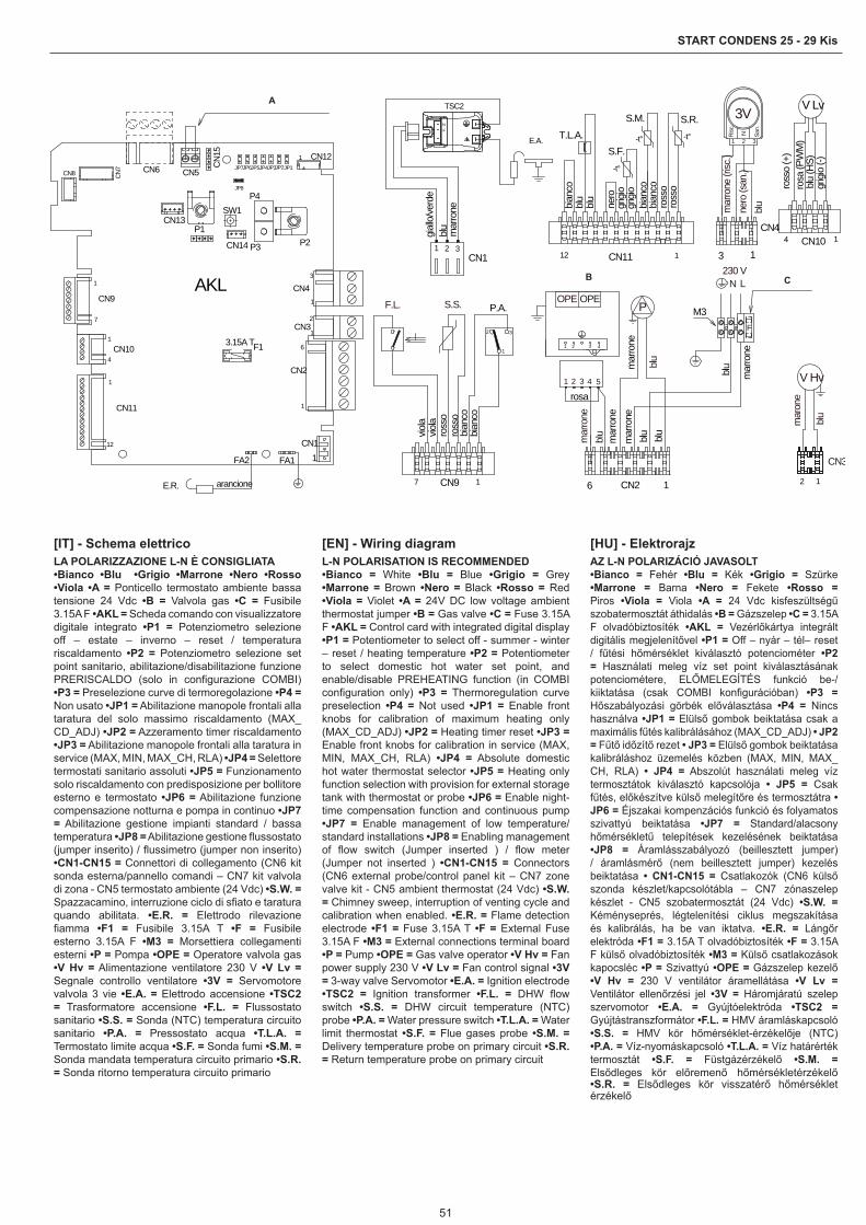
51
START CONDENS 25 - 29 Kis
mar
one
CN3
blu
V Hv
126 1CN2
mar
rone
blu
21 3 54
VALVOLA GAS
1 2 43
OPEOPE
rosa
blu
P
mar
rone
N L Fusibile 3.15A F230 V
M3F
blu
blu
mar
rone
mar
rone
mar
rone
blu
7 1CN9
P.A.
2 3
1
S.S.F.L.
bian
cobi
anco
ross
oro
sso
viola
viola
3V
2
N
1
San.
3
Risc
.
nero
(san
.)m
arro
ne (r
isc.)
blu
3 1
CN4
TSC2
blu
E.A.
mar
rone
gial
lo/v
erde
NF
CN131 2
ross
o (+
)
blu
(HS)
rosa
(PW
M)
grig
io (-
)
CN10
V Lv
14
112 CN11
bian
cobi
anco
S.M.
-t° -t°
S.R.
ross
oro
sso
-t°
S.F.
grig
iogr
igio
nero
T.L.A.
blu
blu
bian
co
CN8 CN
7
1
12
CN11
1
4CN10
1
7
CN9
CN6 CN5
CN121
CN41
3
CN31
2
CN2
1
6
AKL
Ponticello termostato ambiente bassa tensione 24 Vdc
CN11FA1FA2
arancioneE.R.
JP1JP2JP3JP4JP5JP6JP7
JP8
CN
15
P3 P2P1
CN13
CN14
SW1P4
F13.15A T
A
B C
[IT] - Schema elettricoLA POLARIZZAZIONE L-N È CONSIGLIATA•Bianco •Blu •Grigio •Marrone •Nero •Rosso •Viola •A = Ponticello termostato ambiente bassa tensione 24 Vdc •B = Valvola gas •C = Fusibile 3.15A F •AKL = Scheda comando con visualizzatore digitale integrato •P1 = Potenziometro selezione off – estate – inverno – reset / temperatura riscaldamento •P2 = Potenziometro selezione set point sanitario, abilitazione/disabilitazione funzione PRERISCALDO (solo in configurazione COMBI) •P3 = Preselezione curve di termoregolazione •P4 = Non usato •JP1 = Abilitazione manopole frontali alla taratura del solo massimo riscaldamento (MAX_CD_ADJ) •JP2 = Azzeramento timer riscaldamento •JP3 = Abilitazione manopole frontali alla taratura in service (MAX, MIN, MAX_CH, RLA) •JP4 = Selettore termostati sanitario assoluti •JP5 = Funzionamento solo riscaldamento con predisposizione per bollitore esterno e termostato •JP6 = Abilitazione funzione compensazione notturna e pompa in continuo •JP7 = Abilitazione gestione impianti standard / bassa temperatura •JP8 = Abilitazione gestione flussostato (jumper inserito) / flussimetro (jumper non inserito) •CN1-CN15 = Connettori di collegamento (CN6 kit sonda esterna/pannello comandi – CN7 kit valvola di zona - CN5 termostato ambiente (24 Vdc) •S.W. = Spazzacamino, interruzione ciclo di sfiato e taratura quando abilitata. •E.R. = Elettrodo rilevazione fiamma •F1 = Fusibile 3.15A T •F = Fusibile esterno 3.15A F •M3 = Morsettiera collegamenti esterni •P = Pompa •OPE = Operatore valvola gas •V Hv = Alimentazione ventilatore 230 V •V Lv = Segnale controllo ventilatore •3V = Servomotore valvola 3 vie •E.A. = Elettrodo accensione •TSC2 = Trasformatore accensione •F.L. = Flussostato sanitario •S.S. = Sonda (NTC) temperatura circuito sanitario •P.A. = Pressostato acqua •T.L.A. = Termostato limite acqua •S.F. = Sonda fumi •S.M. = Sonda mandata temperatura circuito primario •S.R. = Sonda ritorno temperatura circuito primario
[EN] - Wiring diagramL-N POLARISATION IS RECOMMENDED•Bianco = White •Blu = Blue •Grigio = Grey •Marrone = Brown •Nero = Black •Rosso = Red •Viola = Violet •A = 24V DC low voltage ambient thermostat jumper •B = Gas valve •C = Fuse 3.15A F •AKL = Control card with integrated digital display •P1 = Potentiometer to select off - summer - winter – reset / heating temperature •P2 = Potentiometer to select domestic hot water set point, and enable/disable PREHEATING function (in COMBI configuration only) •P3 = Thermoregulation curve preselection •P4 = Not used •JP1 = Enable front knobs for calibration of maximum heating only (MAX_CD_ADJ) •JP2 = Heating timer reset •JP3 = Enable front knobs for calibration in service (MAX, MIN, MAX_CH, RLA) •JP4 = Absolute domestic hot water thermostat selector •JP5 = Heating only function selection with provision for external storage tank with thermostat or probe •JP6 = Enable night-time compensation function and continuous pump •JP7 = Enable management of low temperature/standard installations •JP8 = Enabling management of flow switch (Jumper inserted ) / flow meter (Jumper not inserted ) •CN1-CN15 = Connectors (CN6 external probe/control panel kit – CN7 zone valve kit - CN5 ambient thermostat (24 Vdc) •S.W. = Chimney sweep, interruption of venting cycle and calibration when enabled. •E.R. = Flame detection electrode •F1 = Fuse 3.15A T •F = External Fuse 3.15A F •M3 = External connections terminal board •P = Pump •OPE = Gas valve operator •V Hv = Fan power supply 230 V •V Lv = Fan control signal •3V = 3-way valve Servomotor •E.A. = Ignition electrode •TSC2 = Ignition transformer •F.L. = DHW flow switch •S.S. = DHW circuit temperature (NTC) probe •P.A. = Water pressure switch •T.L.A. = Water limit thermostat •S.F. = Flue gases probe •S.M. = Delivery temperature probe on primary circuit •S.R. = Return temperature probe on primary circuit
[HU] - ElektrorajzAZ L-N POLARIZÁCIÓ JAVASOLT•Bianco = Fehér •Blu = Kék •Grigio = Szürke •Marrone = Barna •Nero = Fekete •Rosso = Piros •Viola = Viola •A = 24 Vdc kisfeszültségű szobatermosztát áthidalás •B = Gázszelep •C = 3.15A F olvadóbiztosíték •AKL = Vezérlőkártya integrált digitális megjelenítővel •P1 = Off – nyár – tél– reset / fűtési hőmérséklet kiválasztó potenciométer •P2 = Használati meleg víz set point kiválasztásának potenciométere, ELŐMELEGÍTÉS funkció be-/kiiktatása (csak COMBI konfigurációban) •P3 = Hőszabályozási görbék előválasztása •P4 = Nincs használva •JP1 = Elülső gombok beiktatása csak a maximális fűtés kalibrálásához (MAX_CD_ADJ) • JP2 = Fűtő időzítő rezet • JP3 = Elülső gombok beiktatása kalibráláshoz üzemelés közben (MAX, MIN, MAX_CH, RLA) • JP4 = Abszolút használati meleg víz termosztátok kiválasztó kapcsolója • JP5 = Csak fűtés, előkészítve külső melegítőre és termosztátra • JP6 = Éjszakai kompenzációs funkció és folyamatos szivattyú beiktatása •JP7 = Standard/alacsony hőmérsékletű telepítések kezelésének beiktatása •JP8 = Áramlásszabályozó (beillesztett jumper) / áramlásmérő (nem beillesztett jumper) kezelés beiktatása • CN1-CN15 = Csatlakozók (CN6 külső szonda készlet/kapcsolótábla – CN7 zónaszelep készlet - CN5 szobatermosztát (24 Vdc) •S.W. = Kéményseprés, légtelenítési ciklus megszakítása és kalibrálás, ha be van iktatva. •E.R. = Lángőr elektróda •F1 = 3.15A T olvadóbiztosíték •F = 3.15A F külső olvadóbiztosíték •M3 = Külső csatlakozások kapocsléc •P = Szivattyú •OPE = Gázszelep kezelő •V Hv = 230 V ventilátor áramellátása •V Lv = Ventilátor ellenőrzési jel •3V = Háromjáratú szelep szervomotor •E.A. = Gyújtóelektróda •TSC2 = Gyújtástranszformátor •F.L. = HMV áramláskapcsoló •S.S. = HMV kör hőmérséklet-érzékelője (NTC) •P.A. = Víz-nyomáskapcsoló •T.L.A. = Víz határérték termosztát •S.F. = Füstgázérzékelő •S.M. = Elsődleges kör előremenő hőmérsékletérzékelő •S.R. = Elsődleges kör visszatérő hőmérséklet érzékelő

52
START CONDENS 25 - 29 Kis
A
B
T.A.
C
[IT] - Collegamenti bassa tensione e termostato ambiente
A - Le utenze di bassa tensione:C.R. = comando remoto / S.E. = sonda esternaandranno collegate sul connettore CN6 come indicato in figuraB - Per effettuare il collegamento del:T.B.T. = termostato bassa temperatura / A.G. = allarme genericooccorre tagliare a metà il ponticello di colore bianco presente sul connettore CN11 (12 poli) e marcato con la scritta TBT, spellare i fili e utilizzare un morsetto elettrico 2 poli per la giunzione.C - Il termostato ambiente (24Vdc) andrà inserito come indicato dallo schema dopo aver tolto il cavallotto presente sul connettore 2 vie (CN5).T.A. = Termostato ambiente (contatto pulito)
[EN] - Low voltage and ambient thermostat connections
A - Low voltage utilities :C.R. = Remote control / S.E. = External probeconnected to connector CN6, as shown in the figureB - To connect the:T.B.T. = Low temperature thermostat / A.G. = General alarmthe white jumper on the CN11 connector (12-pole) must be cut in half and marked with the inscription TBT, strip the wires and use an 2-pole electrical terminal for joining.C - The ambient thermostat (24Vdc) should be connected as indicated in the diagram once the U-bolt on the 2-way connector (CN5) has been removed.T.A. = ambient thermostat (clean contact)
[HU] - Kisfeszültségű bekötések és szobatermosztát
A - Kisfeszültségű felhasználók:C.R. = távvezérlő / S.E. = külső szondaa CN6 csatlakozóra úgy kell bekötni, ahogy az ábrán láthatóB - Az alábbi bekötéséhez:T.B.T. = alacsony hőmérséklet termosztát / A.G. = általános riasztásvágja ketté a CN11 csatlakozón (12 pólusú) található fehér színű jumpert, megjelölve a TbT felirattal csupaszolja le a vezetékeket és a csatlakoztatáshoz használjon egy 2 pólusú szorítókapcsot.C - A környezeti termosztátot (24Vdc) úgy kell beilleszteni, ahogy a rajzon látható, miután a 2 állású csatlakozón lévő jumpert eltávolította (CN5).T.A. = Szobatermosztát (száraz kapcsolat)
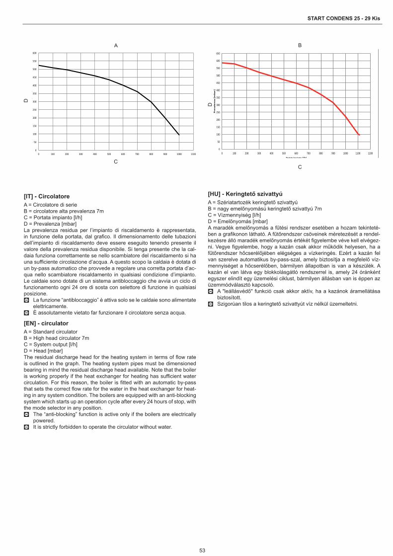
53
START CONDENS 25 - 29 Kis
0
50
100
150
200
250
300
350
400
450
500
550
600
0 100 200 300 400 500 600 700 800 900 1000 1100
[]
A
C
D
0
50
100
150
200
250
300
350
400
450
500
550
600
650
0 100 200 300 400 500 600 700 800 900 1000 1100 1200
Pre
va
len
za [
mb
ar]
Portata impianto [l/h]
B
C
D
[IT] - CircolatoreA = Circolatore di serieB = circolatore alta prevalenza 7mC = Portata impianto [l/h]D = Prevalenza [mbar]La prevalenza residua per l’impianto di riscaldamento è rappresentata, in funzione della portata, dal grafico. Il dimensionamento delle tubazioni dell’impianto di riscaldamento deve essere eseguito tenendo presente il valore della prevalenza residua disponibile. Si tenga presente che la cal-daia funziona correttamente se nello scambiatore del riscaldamento si ha una sufficiente circolazione d’acqua. A questo scopo la caldaia è dotata di un by-pass automatico che provvede a regolare una corretta portata d’ac-qua nello scambiatore riscaldamento in qualsiasi condizione d’impianto. Le caldaie sono dotate di un sistema antibloccaggio che avvia un ciclo di funzionamento ogni 24 ore di sosta con selettore di funzione in qualsiasi posizione.
0 La funzione “antibloccaggio” è attiva solo se le caldaie sono alimentate elettricamente.
0 È assolutamente vietato far funzionare il circolatore senza acqua.
[EN] - circulatorA = Standard circulatorB = High head circulator 7mC = System output [l/h]D = Head [mbar]The residual discharge head for the heating system in terms of flow rate is outlined in the graph. The heating system pipes must be dimensioned bearing in mind the residual discharge head available. Note that the boiler is working properly if the heat exchanger for heating has sufficient water circulation. For this reason, the boiler is fitted with an automatic by-pass that sets the correct flow rate for the water in the heat exchanger for heat-ing in any system condition. The boilers are equipped with an anti-blocking system which starts up an operation cycle after every 24 hours of stop, with the mode selector in any position.
0 The “anti-blocking” function is active only if the boilers are electrically powered.
0 It is strictly forbidden to operate the circulator without water.
[HU] - Keringtető szivattyúA = Szériatartozék keringtető szivattyúB = nagy emelőnyomású keringtető szivattyú 7mC = Vízmennyiség [l/h]D = Emelőnyomás [mbar]A maradék emelőnyomás a fűtési rendszer esetében a hozam tekinteté-ben a grafikonon látható. A fűtőrendszer csöveinek méretezését a rendel-kezésre álló maradék emelőnyomás értékét figyelembe véve kell elvégez-ni. Vegye figyelembe, hogy a kazán csak akkor működik helyesen, ha a fűtőrendszer hőcserélőjében elégséges a vízkeringés. Ezért a kazán fel van szerelve automatikus by-pass-szal, amely biztosítja a megfelelő víz-mennyiséget a hőcserélőben, bármilyen állapotban is van a készülék. A kazán el van látva egy blokkolásgátló rendszerrel is, amely 24 óránként egyszer elindít egy üzemelési ciklust, bármilyen állásban van is éppen az üzemmódválasztó kapcsoló.
0 A "leállásvédő" funkció csak akkor aktív, ha a kazánok áramellátása biztosított.
0 Szigorúan tilos a keringtető szivattyút víz nélkül üzemeltetni.

54
START CONDENS 25 - 29 Kis
5. fig./ábra 6. fig./ábra
1. fig./ábra
3. fig./ábra 4. fig./ábra
25 Kis 29 Kis UML 405 405 mmP 248 248 mmH 792 792 mm
25 29 kg
50 mm 50 mm
200
mm
2. fig./ábra
96
190
7. fig./ábra
8. fig./ábra
9. fig./ábra A
11. fig./ábra
C
10. fig./ábraB
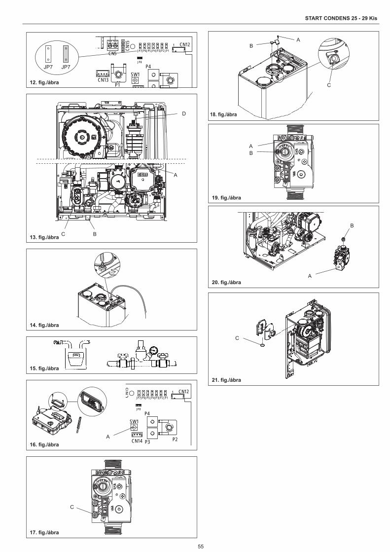
55
START CONDENS 25 - 29 Kis
CN5
CN121JP1JP2JP3JP4JP5JP6JP7
JP8
CN15
P1CN13
SW1P4
12. fig./ábra
JP7 JP7
13. fig./ábra
D
A
C B
14. fig./ábra
15. fig./ábra
16. fig./ábra
CN121JP1JP2JP3JP4JP5JP6JP7
JP8
CN15
P3 P2CN14
SW1P4
A
17. fig./ábra
C
18. fig./ábra
BA
C
19. fig./ábra
BA
21. fig./ábra
C
20. fig./ábra
B
A
A
B

Cod
: 201
1489
8 - 0
2/16
- R
ev. 1