starting with serial chapter ten 10.1, 10.2, 10.9-10.10.6 dr. gheith abandah1
TRANSCRIPT

Starting with serial
Chapter Ten10.1, 10.2, 10.9-10.10.6
Dr. Gheith Abandah 1

Outline
• Introduction• Synchronous data communication• Asynchronous data communication• The 16F87XA USART• Summary
Dr. Gheith Abandah 2

Introduction
Data transfer methods:1.Parallel Transfer– Faster– Expensive– Short distances
2.Serial Transfer– Slower– Cheaper– Short and long distances
Dr. Gheith Abandah 3
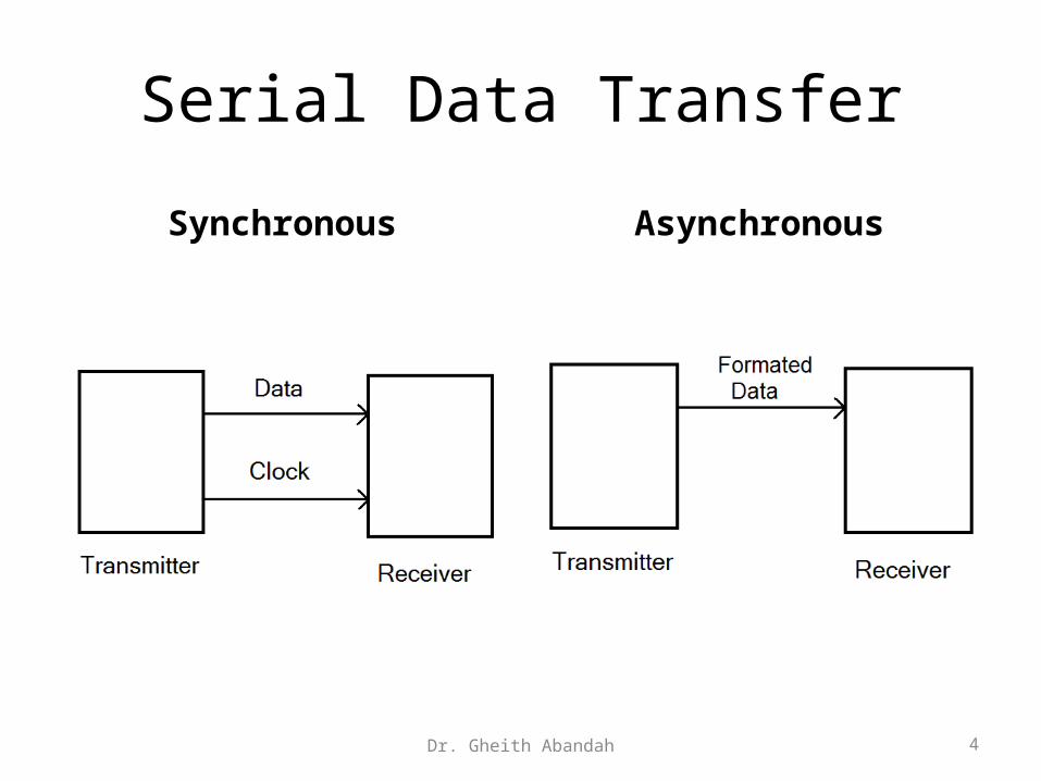
Serial Data Transfer
Synchronous Asynchronous
Dr. Gheith Abandah 4
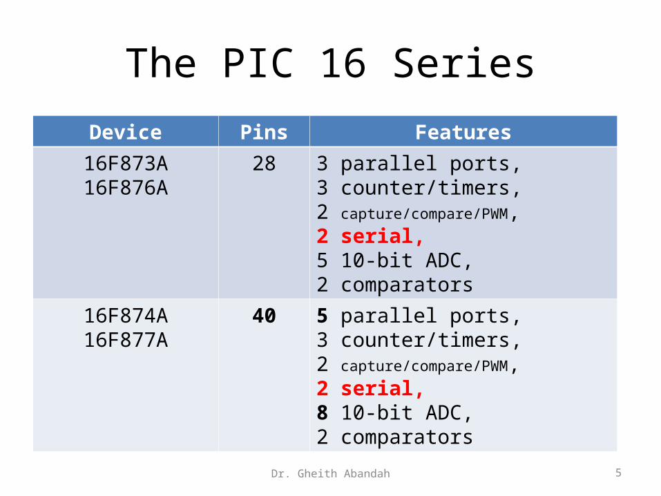
The PIC 16 Series
Device Pins Features
16F873A16F876A
28 3 parallel ports,3 counter/timers,2 capture/compare/PWM,2 serial,5 10-bit ADC,2 comparators
16F874A16F877A
40 5 parallel ports,3 counter/timers,2 capture/compare/PWM,2 serial,8 10-bit ADC,2 comparators
Dr. Gheith Abandah 5
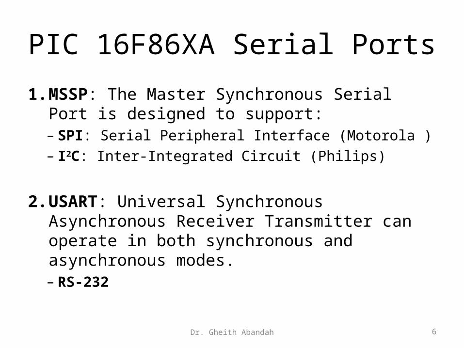
PIC 16F86XA Serial Ports
1. MSSP: The Master Synchronous Serial Port is designed to support:– SPI: Serial Peripheral Interface (Motorola )– I2C: Inter-Integrated Circuit (Philips)
2. USART: Universal Synchronous Asynchronous Receiver Transmitter can operate in both synchronous and asynchronous modes.– RS-232
Dr. Gheith Abandah 6

Synchronous data communication
Dr. Gheith Abandah 7

Shift Register to Receive Data
Dr. Gheith Abandah 8

Synchronous Signals
Dr. Gheith Abandah 9
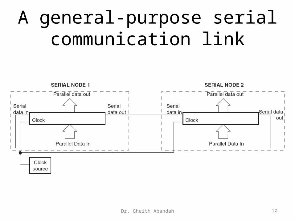
A general-purpose serial communication link
Dr. Gheith Abandah 10

Master/Slave Implementation
Dr. Gheith Abandah 11

Single synchronous master with multiple slaves
Dr. Gheith Abandah 12

Disadvantages of synchronous communication
• An extra line is needed to go to every data node for the clock
• The bandwidth needed for the clock is always twice the bandwidth needed for the data
• Over long distances, clock and data themselves could lose synchronization
Dr. Gheith Abandah 13
Asynchronous principles
• No clock transmitted• Data rate is predetermined – both transmitter
and receiver are preset to recognize the same data rate.
• Each node needs an accurate and stable clock source.
• Each byte or word is framed with a Start and Stop bit. These allow synchronization to be initiated before the data starts to flow.
Dr. Gheith Abandah 14

A common asynchronous serial data format
Dr. Gheith Abandah 15
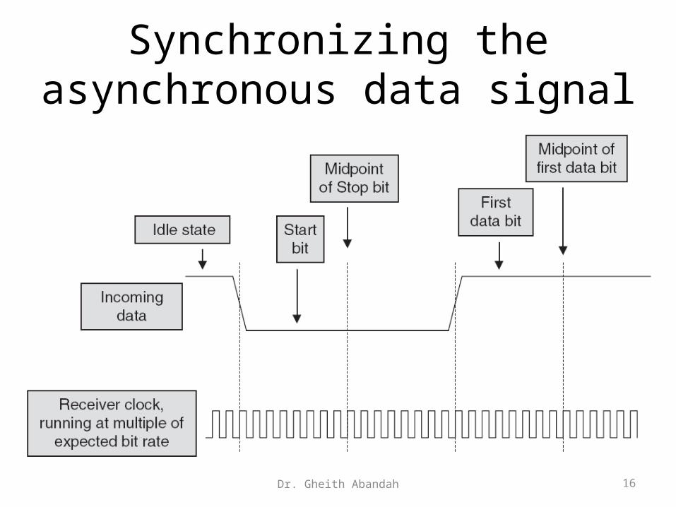
Synchronizing the asynchronous data signal
Dr. Gheith Abandah 16
The 16F87XA USART
• USART: Addressable Universal Synchronous Asynchronous Receiver Transmitter
• Modes:– Synchronous master– Synchronous slave– Asynchronous full-duplex
• Has receive and transmit interrupts• Controlled by TXSTA, RCSTA, and SPBRG
Dr. Gheith Abandah 17
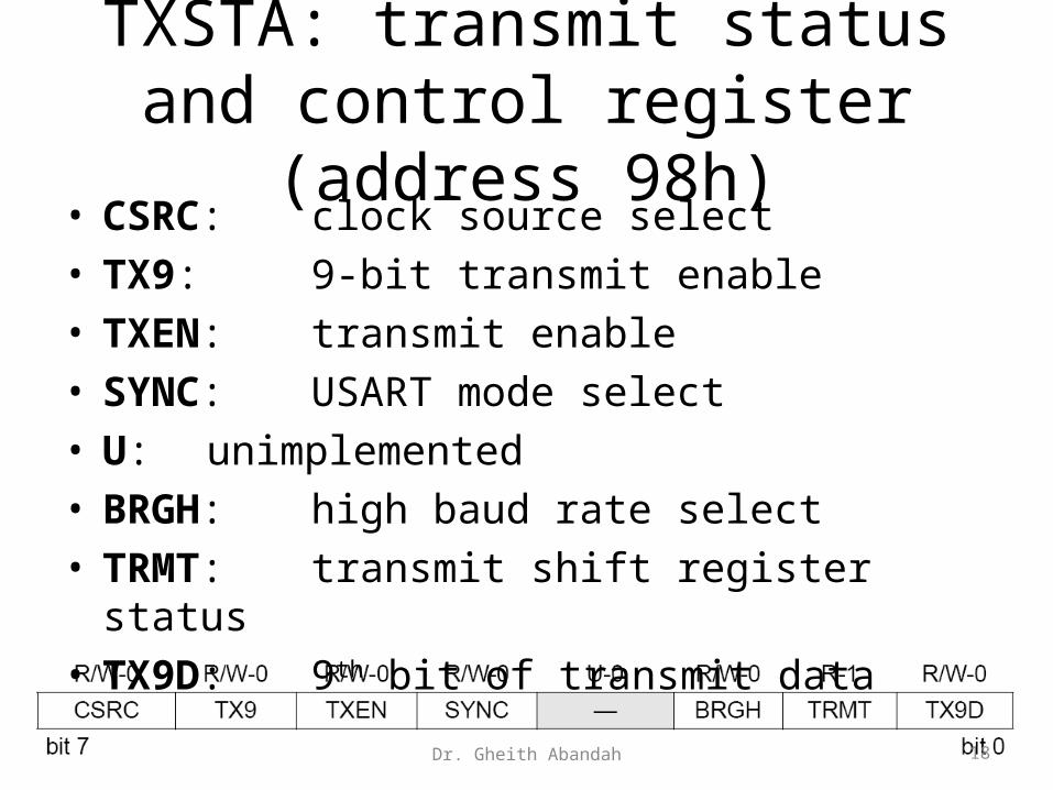
TXSTA: transmit status and control register (address 98h)
• CSRC: clock source select• TX9: 9-bit transmit enable• TXEN: transmit enable• SYNC: USART mode select• U: unimplemented• BRGH: high baud rate select• TRMT: transmit shift register status• TX9D: 9th bit of transmit data
Dr. Gheith Abandah 18

RCSTA: receive status and control register (address 18h)
• SPEN: serial port enable• RX9: 9-bit receive enable• SREN: single receive enable• CREN: continuous receive enable• ADDEN: address detect enable• FERR: framing error• OERR: overrun error• RX9D: 9th bit of received data
Dr. Gheith Abandah 19
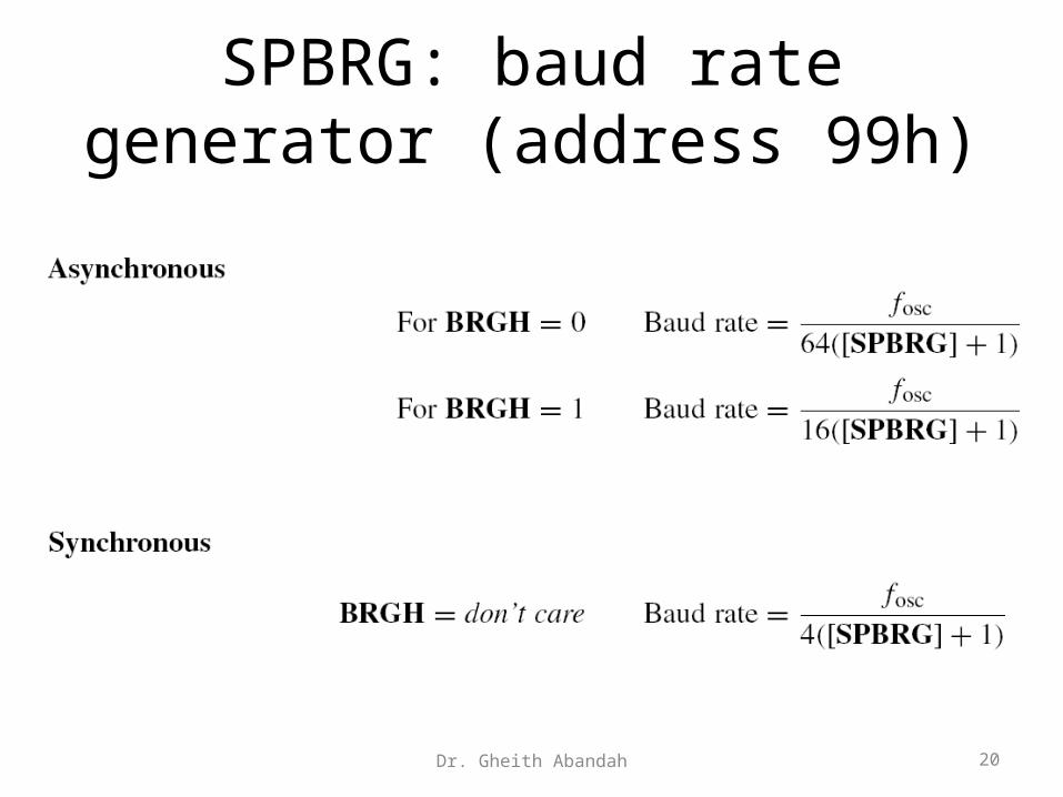
SPBRG: baud rate generator (address 99h)
Dr. Gheith Abandah 20
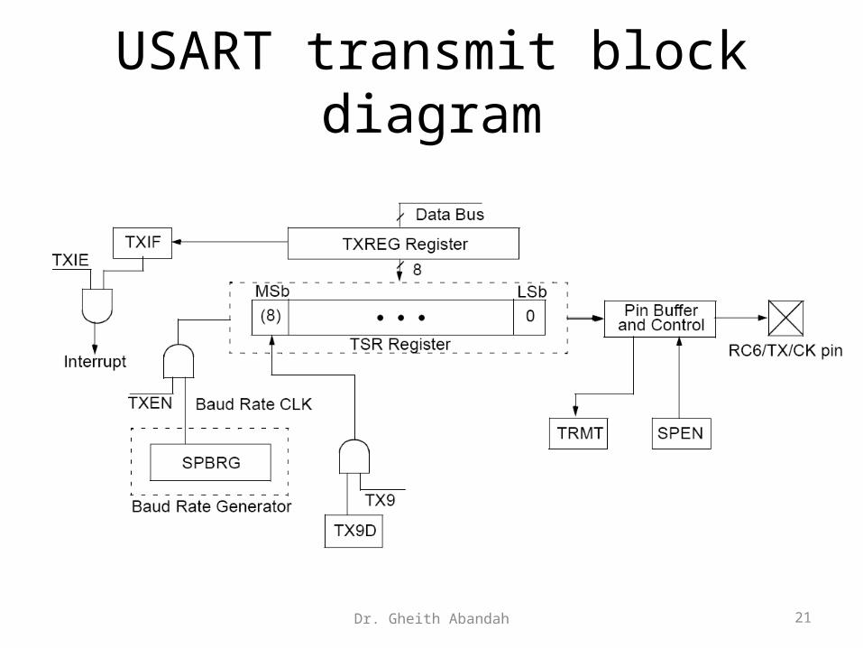
USART transmit block diagram
Dr. Gheith Abandah 21

USART receive block diagram
Dr. Gheith Abandah 22

Serial Communications Example
Dr. Gheith Abandah 23
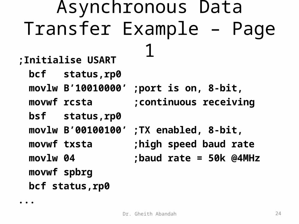
Asynchronous Data Transfer Example – Page 1
;Initialise USART
bcf status,rp0
movlw B’10010000’ ;port is on, 8-bit,
movwf rcsta ;continuous receiving
bsf status,rp0
movlw B’00100100’ ;TX enabled, 8-bit,
movwf txsta ;high speed baud rate
movlw 04 ;baud rate = 50k @4MHz
movwf spbrg
bcf status,rp0
...Dr. Gheith Abandah 24

Asynchronous Data Transfer Example – Page 2
;*********************************************
;ISR. On external interrupt, SSP reads byte
;from Hand Controller, sends it out on USART,
;receives it back through USART,
;and echoes it back to keypad.
;Received Byte stored in I2C_RX_word
;*********************************************
Interrupt_SR
...
Dr. Gheith Abandah 25

Asynchronous Data Transfer Example – Page 3
;send out via async comm channel
bcf pir1,rcif ;clear RX interrupt flag
movf I2C_RX_word,0 ;get word
movwf txreg
btfss pir1,rcif ;test for RX INT flag,
;indicating receive complete
goto $-1
movf rcreg,0 ;get and store RX word
movwf async_RX_word
...Dr. Gheith Abandah 26

Asynchronous Waveform
Dr. Gheith Abandah 27

Using address detection with the USART receive mode
• Multiple nodes can be connected to the serial line and a node can recognize its own address.
• Set 9-bit mode RX9 and address enable bit ADDEN• Logic 1 in the ninth bit indicates that an address is
received.• If byte equals own address, revert to normal
reception by resetting ADDEN• This continues until a further address word is
detected, which may be for another node.
Dr. Gheith Abandah 28

Summary• There are two broad types of serial communication:
synchronous and asynchronous.• There are a very large number of different standards and
protocols for serial communication, ranging from the very simple to the seriously complicated. It is important to match the right protocol with the right application.
• The 16F873A microcontroller has two extremely flexible serial ports. The cost of flexibility is a significant level of complexity in grasping their use. Therefore, it is often worth adapting publicly available routines to use, rather than starting from scratch in writing new code.
Dr. Gheith Abandah 29