state of alaska - dot.state.ak.us · web vieweach section of this template includes...
TRANSCRIPT

INSTRUCTIONS (delete this section before printing)
ALASKA DEPARTMENT OF TRANSPORTATION and PUBLIC FACILITIES
CENTRAL REGION
DSR TEMPLATE
BASED ON:
Alaska Highway Preconstruction Manual (HPCM), Alaska Department of Transportation and
Public Facilities, 2005 (as amended)
The Design Study Report (DSR) is a formal report that documents the selection of a preferred design alternative. To help you develop your DSR, the DOT&PF Central Region has created this electronic DSR template, designed to guide you through the DSR development process and ensure your DSR includes all the necessary sections stated in the Alaska Highway Preconstruction Manual (HPCM), section 450.5. An electronic version of the HPCM and the latest revisions can be found at http://www.dot.state.ak.us/stwddes/dcsprecon/preconmanual.shtml.
This template covers procedures and sections required by the HPCM; however, you must customize this template to reflect project specifics.
Using the DSR Template
Each section of this template includes “instructions” and space for “project information.” You should read the instructions for each section to help complete the document. This template was developed in Word so you can easily add tables and additional text. Some sections may require only a brief description while others may require several pages of explanation.
Instruction text is shown as:Instruction Text: To be deleted as sections are filled in.
Instructions contain examples of how you might fill in a section. If you choose to use an example in your DSR select the text and change the format from “Instructions” to “Normal”.
If a section (1.0, 2.0, 3.0, etc.) is not used in the DSR, do not renumber the section. Instead include a statement that the section is not applicable to the project.
Deleting “Template” watermark: To delete the “Template” watermark, open the header/footer and delete the watermark image. You will need to do this twice, once for the title page and then for the Table of Contents section.
Revised May 2019

Revision History:
April 2014• Original Version.
February 2015• Added revision history & comment contact info• Modified Section 2.0 Design Standards and Guidelines to include an option of breaking standards
and guidelines apart. • Added language about considering single lane roundabouts where new traffic signals are being
considered in Section 11 Traffic Analysis• Modified Section 16.3 example language• Modified Section 18 Cost Estimate table and instructions
June 2016• Reworded instructions for Section 16.2 Public Information Plan • Added language to Section 12.0 Safety Improvements about new CR Highway Lighting
Guidance• Added required company information to signature page• General cleanup of existing designer notes
November 2017• Fixed some formatting issues and fixed navigation bar • Updated Section 2.0 Design Standards and Guidelines to reflect current standards• Updated various hyperlinks • Modified various sections example language• Added additional instructions on ARRC Checklist to Section 15 Utility Relocation and
Coordination • Modified instructions for DSR distribution and revision methodology
May 2019• Fixed some formatting and navigation bar issues• Updated to match DOT&PF Branding Guidelines• Removed ADA Transition Memo Appendix• Added commonly used acronyms to Acronym List• Minor edits to instruction text throughout
Comments, Questions, Frustrations:
While using this template, keep in mind this is a dynamic document and your comments are welcome. Please send any comments or questions to:
CR Standards Engineer: Chris Post, P.E. (907) 269-0585 or [email protected]

Include the full project name. If the project has federal funding include the federal number and DOT&PF program number. However, the prefix on the federal number should be dropped.
EXAMPLE: BR-BH-NH-0A31(35)/CFHWY00100 should be 0A31(35)/CFHWY00100 or 0A3135/CFHWY00100.
PROJECT NAME
Project No.: Federal/State
DESIGN STUDY REPORT
ALASKADEPARTMENT OF TRANSPORTATION
AND PUBLIC FACILITIES
PREPARED BY: Company NameAddressAddress
Consultants should use their company name and address. In-house staff use: DOT&PF Central Region – Design and Construction 4111 Aviation Avenue Anchorage, AK 99502.
Month, Year

ALASKADEPARTMENT OF TRANSPORTATION AND PUBLIC FACILITIES
DESIGN AND ENGINEERING SERVICES – CENTRAL REGION
DESIGN STUDY REPORT
For
Project Name
Project No.: Federal/State
Replace seal with the Project Engineers seal. Written by header is optional for the EIT to have their name on the document. Delete if not used.
Written by: Insert Name
Prepared by:
__________________________________Name of Project Engineer DateProject EngineerCompany NamePhysical AddressPhysical AddressPhone NumberCert. of Auth. Number
Concur by:
__________________________________Name of Project Manager DateProject Manager
Concur by:
__________________________________ Name of Section Chief Date
Chief Title
Approved:
__________________________________John R. Linnell, P.E. DatePreconstruction Engineer
James E. Amundsen, P.E.
Highway Design Group Chief
Luke S. Bowland, P.E
Aviation Design Group Chief
Eric Miyashiro, P.E.
PD&E Group Chief
NOTICE TO USERS
This report reflects the thinking and design decisions at the time of publication. Changes frequently occur during the evolution of the design process, so persons who may rely on information contained in this document should check with the Alaska Department of Transportation and Public Facilities for the most current design. Contact the Design Project Manager, Name of Project Manager, at 907-269-#### for this information.
PLANNING CONSISTENCY
This document has been prepared by the Alaska Department of Transportation and Public Facilities according to currently acceptable design standards and Federal regulations, and with the input offered by the local government and public. The department's Planning Section has reviewed and approved this report as being consistent with present community planning.
CERTIFICATION
For Federally-funded projects, include the first paragraph. For State-funded projects, include the second paragraph:
Federally-funded Project:
The Alaska Department of Transportation and Public Facilities hereby certify that this document was prepared in accordance with Section 520.4.1 of the current edition of the department's Highway Preconstruction Manual and CFR Title 23, Highway Section 771.111(h).
State-funded Only Project:
The Alaska Department of Transportation and Public Facilities hereby certify that this document was prepared in accordance with Section 520.4.2 of the current edition of the department's Highway Preconstruction Manual.
Always include the following paragraph.
The department has considered the project's social and economic effects upon the community, its impacts on the environment and its consistency with planning goals and objectives as approved by the local community. All records are on file with Central Region - Design and Engineering Services Division, Highway Design Section, 4111 Aviation Avenue, Anchorage, AK 99502.
John R. Linnell, P.E. Date Todd Vanhove DatePreconstruction Engineer Chief, Planning


TABLE OF CONTENTS
To update the table of contents, right-click inside the shaded area and choose “Update Field”. You can choose to “Update page numbers only” or “Update entire table” if you want to update the page numbers and the text.
This is an automatic format based table. If additional sections are desired below you must apply heading styles (i.e. Heading 1 or Heading 2) to the text that you want to include in the table of contents. This can be done by copying the format of another section or by selecting the text of the heading, click the “Home” tab and select the appropriate heading style in the “Styles” ribbon.
LIST OF FIGURES....................................................................................................................................iiiLIST OF ACRONYMS..............................................................................................................................iii1.0 PROJECT DESCRIPTION..................................................................................................................1
1.1 Project Location and Description......................................................................................................11.2 Existing Facilities and Land Use.......................................................................................................11.3 Purpose and Need..............................................................................................................................1
2.0 DESIGN STANDARDS AND GUIDELINES.....................................................................................23.0 DISCUSSION OF ALTERNATIVES..................................................................................................3
3.1 First Alternative.................................................................................................................................33.2 Second Alternative.............................................................................................................................33.3 Third Alternative................................................................................................................................3
4.0 PREFERRED ALTERNATIVE...........................................................................................................35.0 TYPICAL SECTIONS..........................................................................................................................36.0 HORIZONTAL AND VERTICAL ALIGNMENT............................................................................3
6.1 Horizontal Alignment........................................................................................................................36.2 Vertical Alignment............................................................................................................................3
7.0 EROSION AND SEDIMENT CONTROL..........................................................................................38.0 DRAINAGE............................................................................................................................................49.0 SOIL CONDITIONS.............................................................................................................................510.0 ACCESS CONTROL FEATURES....................................................................................................511.0 TRAFFIC ANALYSIS.........................................................................................................................612.0 SAFETY IMPROVEMENTS.............................................................................................................613.0 RIGHT-OF-WAY REQUIREMENTS..............................................................................................614.0 PEDESTRIAN AND BICYCLE FACILITIES.................................................................................715.0 UTILITY RELOCATION AND COORDINATION.......................................................................7
15.1 Utility Company..............................................................................................................................715.2 Utility Company..............................................................................................................................7
16.0 PRELIMINARY WORK ZONE TRAFFIC CONTROL................................................................716.1 Traffic Control Plan (TCP)..............................................................................................................816.2 Public Information Plan (PIP)..........................................................................................................816.3 Transportation Operations Plan (TOP)............................................................................................9
17.0 STRUCTURAL SECTION AND PAVEMENT DESIGN...............................................................918.0 COST ESTIMATE...............................................................................................................................919.0 ENVIRONMENTAL COMMITMENTS AND CONSIDERATIONS.........................................10
Project Name i Design Study Report

20.0 BRIDGES............................................................................................................................................1021.0 EXCEPTIONS TO DESIGN STANDARDS...................................................................................1022.0 MAINTENANCE CONSIDERATIONS.........................................................................................1023.0 ITS FEATURES.................................................................................................................................10
APPENDIX A Approved Design Criteria and Design Designation
APPENDIX B Typical Sections
APPENDIX C 3R Analysis
APPENDIX D Traffic Analysis
APPENDIX E Material Recommendations
APPENDIX F VE Consideration
APPENDIX G Approved Environmental Document
APPENDIX H Approved Design Exceptions and Design Waivers
APPENDIX I ITS Systems Engineering Analysis
APPENDIX J Design Memos
Project Name ii Design Study Report

Figures and Appendices to the DSR should include the following items if completed or available. (Other appendices might include HSIP Candidate Description and Cost Estimate Summary, Material Report, As-built Drawings, MOAs, UCRs, etc.). Edit as needed.
LIST OF FIGURES
Figure 1 Location & Vicinity Map
The list of acronyms below is only an example. Edit as needed.
LIST OF ACRONYMS
AADT Annual Average Daily TrafficAASHTO American Association of State Highway and Transportation OfficialsAHDM Alaska Highway Drainage ManualANSI American National Standards InstituteAPDES Alaska Pollutant Discharge Elimination SystemARRC Alaska Railroad Corporation ATM Alaska Traffic Manual ATMS Alaska Traffic Manual SupplementBMP Best Management PracticeCFR Code of Federal RegulationsCGP Alaska Construction General PermitDEC Alaska Department of Environmental ConservationDOT U.S. Department of TransportationDOT&PF Alaska Department of Transportation and Public FacilitiesDOJ U.S. Department of JusticeESCP Erosion and Sediment Control PlanEPA Environmental Protection Agency FHWA Federal Highway AdministrationHMA Hot Mix AsphaltHPCM Alaska Highway Preconstruction ManualHMCP Hazardous Material Control PlanHSIP Highway Safety Improvement ProgramIES Illuminating Engineering Society KPB Kenai Peninsula BoroughLOS Level of ServiceMADT Monthly Average Daily TrafficMOA Municipality of AnchorageMP MilepostMPH Miles per HourMS4 Municipal Separate Storm Sewer SystemsMSB Matanuska-Susitna BoroughMUTCD Manual on Uniform Traffic Control DevicesNPDES National Pollutant Discharge Elimination SystemPGDHS A Policy on Geometric Design of Highways and StreetsPIP Public Information PlanPROWAG Proposed Accessibility Standards for Pedestrian Facilities in the Public Right-of-WayRDG Roadside Design GuideROW Right-of-WaySWMM Storm Water Management Model
Project Name iii Design Study Report

SWPPP Storm Water Pollution Prevention PlanTMP Traffic Management PlanTOP Transportation Operations PlanTRB Transportation Research BoardUSGS United States Geological Survey
Project Name iv Design Study Report

Below is an example of a Location and Vicinity Map. Note: Mile points or mileposts are preferred over stations because project stationing may change during the design of the project.
Project Name v Design Study Report

Figure 1 Location and Vicinity Map
Project Name vi Design Study Report

PROJECT DESCRIPTION
Description of project location, existing facilities, and purpose and need for proposed project are all subsections of Project Description.
1.1 Project Location and Description
Describe the project limits using mileposts or streets. One way to find the latitude and longitude is to use Google Earth centered on the middle of the project. USGS map data can be found at: https://viewer.nationalmap.gov/viewer/?p=default&b=base1&x=-16260009.070459228&y=9684407.696967477&l=4&v=US_Topo%3A0%3B1%3B2# .
Please use decimal format when citing Lat/Long. This will be used to geo-reference the document in eDocs.
LOCATION EXAMPLE:
The Alaska Department of Transportation and Public Facilities (DOT&PF) in cooperation with the Federal Highway Administration (FHWA) proposes to extend the northbound passing lane from the terminus of the current passing lane, near Milepost 99, to Milepost 100. The project is located in Sections 14 and 15 Township 10N, Range 1 W., Seward Meridian, USGS Topographical Map Seward D-7; Latitude 60.955014°N, Longitude 149.419264°W, within the Municipality of Anchorage (MOA) near the community of Bird, Alaska. See Figure 1 for Location & Vicinity Map.
DESCRIPTION EXAMPLE:
The proposed rehabilitation project includes; extending the 12-foot northbound passing lane with an 8-foot shoulder by widening on the north side approximately 1.1 miles, extending the pedestrian undercrossing, and realigning the pathway to accommodate the pedestrian undercrossing extension. Work also includes resurfacing the existing roadway, improving ditches and drainage, removing/replacing guardrail, improving drainage culverts, relocating and constructing utilities, replacing signage, striping, and re-vegetation of the disturbed area once construction is complete.
1.2 Existing Facilities and Land Use
Provide some history of the project area. This will require as-built and prior DSR research. As-built plans and DSR’s can be found in the Central Files within the Highway Design section (4111 Aviation Ave. Anchorage, AK 99502) – electronic copies are now available for both as-built plans and DSRs internally (i.e. LIB\ARCHIVE folder). As-builts are available at http://www.dot.state.ak.us/edocs_code/searches/combined_asbuilt_search.cfm for external folks.
Describe the physical characteristics of the land and its primary uses.
1.3 Purpose and Need
Provide a general purpose statement followed by the specific purpose and need for the proposed project. (This should closely resemble the Environmental Document’s purpose and need statement.)
EXAMPLE:
The purpose of a 3R (Resurface, Restoration, and Rehabilitation) project is to extend the service life and enhance both safety and capacity, as needed.
Project Name 1 Design Study Report

DESIGN STANDARDS AND GUIDELINES
Design standards and guidelines that apply to the project name are contained in the following publications:
Below are examples of design standards and guidelines. Modify lists as needed.
For additional manuals not shown, use the following format:
Name of Manual/Handbook, X Edition, Name of Author/Association, Year.
Standards:
A Policy on Geometric Design of Highways and Streets (PGDHS) , 6th Edition, AASHTO, 2011. Roadside Design Guide (RDG) , 4th Edition, AASHTO, 2011. Alaska Highway Preconstruction Manual (HPCM) , DOT&PF, 2005 as amended. Alaska Highway Drainage Manual (AHDM) , DOT&PF, 2006. The Alaska Traffic Manual (ATM), consisting of the Manual on Uniform Traffic Control Devices
(MUTCD), 2009 as amended, U.S. DOT, FHWA) and the Alaska Traffic Manual Supplement (ATMS), DOT&PF, 2016.
ADA Standards for Transportation Facilities , DOT, 2006. ADA Standards for Accessible Design , DOJ, 2010. Guide for the Development of Bicycle Facilities , 4th Edition, AASHTO, 2012. Recommended Practice for Roadway Lighting (RP-8-14), ANSI / IES, 2014. Highway Capacity Manual (HCM) , 5th Edition, TRB, 2010. Guidelines for Geometric Design of Very Low-Volume Local Roads (ADT ≤ 400) , AASHTO,
2001. Include the reference below when working on a MOA-owned facility and are following their standards.
Design Criteria Manual (DCM) , MOA, Project Management & Engineering Department, 2007 with 2018 revision.
Optional if you wish to include guidelinesGuidelines:
Proposed Accessibility Standards for Pedestrian Facilities in the Public Right-of-Way (PROWAG), U.S. Access Board, 2011.
Guide for the Planning, Design, and Operation of Pedestrian Facilities , 1st Edition, AASHTO, 2004.
Use the current accepted design standards. If you are not using the current adopted design standard you must explain why and verify whether a Design Waiver/Exception is required.
Appendix ___ contains the project Design Criteria and Design Designation.
DISCUSSION OF ALTERNATIVES
Mention that design alternatives were analyzed as part of the Preliminary Engineering Report (PER)/Environmental Document.
Provide a description and comparative differences of the design alternatives.
3.1 First Alternative
The first alternative is the No-Build alternative.
Project Name 2 Design Study Report

3.2 Second Alternative
3.3 Third Alternative
PREFERRED ALTERNATIVE
Discuss the preferred alternative in more detail. Why was this alternative selected?
TYPICAL SECTIONS
Discuss roadway, bridge, sidewalk, and pathway typical sections here. Number of lanes (each direction), lane and shoulder widths, embankment foreslopes and backslopes, ditch types and widths, rumble strips, etc.
The typical sections are provided in Appendix ___.
HORIZONTAL AND VERTICAL ALIGNMENT
Discuss general horizontal and vertical alignment, including location of bridges and other structures.
6.1 Horizontal Alignment
6.2 Vertical Alignment
EROSION AND SEDIMENT CONTROL
Provide a description of the Erosion and Sediment Control on the project.
EXAMPLE:
The project includes temporary and permanent measures to control or prevent erosion and sedimentation during and post project construction. The contractor will prepare a Storm Water Pollution Prevention Plan (SWPPP) prior to construction that conforms to the DOT&PF Best Management Practices (BMPs) for Erosion and Sediment Control in accordance with the DOT&PF contract specifications and follows the guidelines of the Erosion and Sediment Control Plan (ESCP) provided to the contractor. The contractor will submit the SWPPP for approval by the Construction Project Engineer. The contractor will conduct construction activities in accordance with the approved SWPPP. Appropriate erosion and siltation controls will be used and maintained in optimal condition during construction and all other exposed soils/fills will be permanently stabilized. Temporary BMP’s will remain in place until permanent erosion and sediment control measures are in place and soil is permanently stabilized.
DRAINAGE
Add information about the general drainage of your project. The first paragraph or two should address project specific characteristics.
EXAMPLES:
Project Name 3 Design Study Report

3R Project – No widening, Change in Vertical Grade, No significant change to current drainage patterns or discharge point
The project will reestablish the v-ditch running along the east side of the roadway. No storm drain pipes are present along the project corridor. Culverts will be placed to maintain existing storm water flow patterns. Some of the existing culverts will be upsized to improve current conditions. The storm water may flow into the South Fork of Campbell Creek (located approximately 0.40 mile to the north). Due to topographical constraints and spatial separation, there is no potential for storm water to flow beyond the roadside ditches and into the Class A wetland on Trappers Trail Road (located upslope of proposed construction activities).
3R Project – Widening to add passing lane, Rock blasting, Widening ditches, Pathway realignment, Culvert replacement and up-sizing, more impervious area, No significant changes to current drainage patterns or discharge point
The project will widen the roadway to accommodate the extension of the northbound passing lane. The additional lane will increase the width from 40 feet to 52 feet. The newly constructed flat bottom ditches running along the north side of the roadway will be wider than the existing ditches to improve accessibility for Maintenance and Operations, improve drainage, and alleviate rock falls from entering the roadway. A flat bottom ditch will be constructed along the north side of the pathway realignment to improve an identified drainage problem. Throughout the project, culverts will be replaced and riprap will be added to inlets and outlets, as needed. Generally within the project area, surface water moves via ditches into culverts, then passes beneath the Seward Highway and the ARRC tracks before entering the north shore of Turnagain Arm.
8.1 Drainage within the Municipality of Anchorage (MOA) and MS4 Permit Compliance
This section only applies to projects located within the Municipality of Anchorage that are covered by the MS4 permit area. Delete section if not applicable.
There are two guiding documents that need to be addressed in the DSR: the Drainage Project Coordination Policy MOU and the MS4 permit. It’s recommended that the Designer review the both documents prior to writing this section.
Add information concerning compliance to the Drainage MOU and MS4 permit. As part of the Drainage MOU, update the language based on the scope of the project. All work should be discussed with the Environmental Analyst and should match the work covered in the Environmental Document and permits.
EXAMPLE:
The National Pollutant Discharge Elimination System permit program originated under section 402 of the Clean Water Act (CWA, 33 USC §1251), and requires that stormwater discharges to surface water be authorized by permit. In Alaska, the Alaska Department of Environmental Conservation (DEC) has primacy for issuing these permits via the Alaska Pollutant Discharge Elimination System (APDES). DEC has jointly authorized the Municipality of Anchorage (MOA) and the DOT&PF to discharge stormwater from municipal separate storm sewer systems (MS4) to surface water and wetlands within the MOA through an individual MS4 permit. This permit, APDES Permit No. AKS052558, is effective from August 1, 2015 to July 31, 2020.
To comply with the permit; the project will incorporate, at a minimum, the pollution control measures and Best Management Practices (BMPs) as required by the DEC-approved Storm Water Management Program (SWMP) developed by the MOA. Essential requirements include but are not necessarily limited to:
• The project follows the criteria set forth in the DOT&PF’s Alaska Highway Drainage Manual and the MOA’s Drainage Design Guidelines as modified by DOT&PF.
Project Name 4 Design Study Report

• The contractor will develop a SWPPP prior to construction that follows the guidelines of the ESCP provided to the contractor. The SWPPP will comply with the APDES permitting program and the Alaska Construction General Permit (CGP).
• The contractor will describe how to minimize and reduce erosion in the contractor’s SWPPP.
• The contractor will comply with all permit conditions with respect to installation and maintenance of control measures, inspections, monitoring (if necessary), corrective actions, reporting and recordkeeping.
• The contractor will address all discharge in the SWPPP. The contractor will prepare a Hazardous Material Control Plan (HMCP).
• The maintenance of the pipes, sewers, and other conveyances will remain the responsibility of the AGENCY.
• State of Alaska will maintain outreach and education through the State of Alaska website. Project specific information will be posted at the project site once construction activity begins.
SOIL CONDITIONS
Discuss the soil conditions in the project area. Use resources including the Environmental Document, geotechnical reports or the pavement recommendations to develop this section.
EXAMPLE:
A geotechnical report is being developed for this project. Areas of rock excavation were determined by visual inspection during site visits and using Google Maps. Geotechnical information taken from the MP 99-105 Preliminary Engineering Report and MP 96-102 Design Study Report indicates the soil in this area to be relatively consistent. The soils consist of silty sand with gravel and silty gravels with sand and cobbles. The material is dense to very dense with varying amounts of non-plastic fines. Bedrock consists of dark gray, slightly weathered argillite and greywacke.
ACCESS CONTROL FEATURES
Use the statement below if it applies to your project.
New access to the highway will be managed through driveway permits and future project evaluation.
TRAFFIC ANALYSIS
Discuss the traffic analyses done to support the need for specific project features such as:
Addition of turn lanes
Widening of shoulders, or
Installation of traffic signals
Analyses can include:
Signal warrants*
Capacity analysis, or
Roundabout analysis
Discuss reported crashes as appropriate.
Project Name 5 Design Study Report

*DOT&PF has a Roundabout First Policy that requires a single lane roundabout be considered at all locations where a new traffic signal is being considered. Justification for not installing a roundabout needs to be included in the DSR (Section 430.5.5).
SAFETY IMPROVEMENTS
Discuss project specific safety improvement features included that will reduce known or potential safety deficiencies. If the project is an HSIP project, include the original project nomination in the appendix of this report.
Use the Moose-Vehicle Priority List 2006-2010 as a guide to areas of concern. If the proposed 3R, 4R or other major funding project is in one of the locations on the 95 percentile list discuss the ranking of the road and make sure the project considers benefit/cost of mitigation possibilities: vegetation management, off-site habitat/corridors, lighting, fencing, etc.
Before including continuous highway lighting, refer to the Highway Lighting Guidance Memo at: http://www.dot.state.ak.us/creg/design/highways/Design_Guidance/16-12-19_CR_LIGHTING_BILLING_GUIDANCE.pdf
RIGHT-OF-WAY REQUIREMENTS
Will the proposed project require additional ROW? If so, describe where and how much. Where will all permanent work be constructed? Within the existing Right-of-Way? Easements? Permitted ARRC Right-of-Way?
If the proposed project requires additional ROW describe the type of acquisitions (full, partial, strip etc.) that may be needed, but do not say how many. If possible, use words like approximately.
EXAMPLE:
The Abbott Road Rehabilitation Project will require additional ROW.
The first half of the project (from Lake Otis Parkway to Elmore Road) will have little need for additional rights. The preferred alternative shifts the alignment to the south of the existing centerline, minimizing ROW impacts.
The second half of the project (Elmore Road to Birch Road) passes through a more narrow ROW corridor (averaging approximately 100-130 feet in total width), with rolling topography. ROW acquisitions in this section are largely strip acquisitions, predominately on the south side of Abbott Road.
Temporary Construction Easements and Permits will be required to construct the project.
PEDESTRIAN AND BICYCLE FACILITIES
Discuss pedestrian and bicycle accommodations. This includes but is not limited to: Shoulders, bike lanes, sidewalks, shared pathways, and pedestrian undercrossings.
UTILITY RELOCATION AND COORDINATION
ARRC Crossing Coordination: For all projects, the project team must fill out the Railroad Crossing Engineer’s Checklist (found here: http://www.dot.state.ak.us/creg/design/highways/Submittals/ARRC_Certification/ )
Project Name 6 Design Study Report

The design team should follow the flowchart (page 3) to determine which forms need to be included along with the checklist. At the time of draft DSR submittal, submit the entire ARRC Crossing Certification package for review.
Utility companies with facilities in the project limits include _____________________. Utilities will require relocation and agreements will need to be developed, at select locations throughout the project, to address the following conflicts:
15.1 Utility Company
15.2 Utility Company
PRELIMINARY WORK ZONE TRAFFIC CONTROL
This section should follow the HPCM Chapter 14. Please see example language below regarding requirements set forth by Chapter 14.
EXAMPLE (Significant):
The HPCM, Section 1400.2 sets forth the criteria for determining if a project is ‘significant’ for purposes of determining the level of effort required in developing a Traffic Management Plan (TMP). Significant projects fall into either a Category 1 or Category 2 classification.
Category 1:
Project occupies a location for more than three days with either intermittent or continuous lane closures on Interstate Highways within a Transportation Management Area – Criteria Met or Criteria Not Met
Category 2:
Project occupies a location for more than three days with either intermittent or continuous lane closures on arterials, expressway, or freeways with Annual Average Daily Traffic (AADT) of 30,000 or more – Criteria Met or Criteria Not Met
Project fully closes an arterial for more than one hour at a time with no practical alternate route – Criteria Met or Criteria Not Met
Any project that, alone or in combination with other concurrent projects nearby, is anticipated to require greater than normal attention to traffic control to eliminate sustained work zone impacts greater than what would be considered acceptable – Criteria Met or Criteria Not Met
Therefore, the project is considered a Category 2 “Significant Project” and a full Traffic Management Plan, including Transportation Operations, Public Information, and Traffic Control Plans, will be developed.
EXAMPLE (Significant):
The HPCM, Section 1400.2 sets forth the criteria for determining if a project is to be classified as a “Significant Project” for purposes of determining the level of effort required in developing a TMP. This project meets the definition of “Significant” and therefore requires a Traffic Management Plan. The TMP herein addresses delays and queuing times by limiting road closures to night time on weekdays only. Components of the TMP that are required include a Traffic Control Plan, Public Information Plan, and Transportation Operations Plan.
Project Name 7 Design Study Report

EXAMPLE (Not Significant Project):
The HPCM, Section 1400.2 sets forth the criteria for determining if a project is to be classified as a “Significant Project” for purposes of determining the level of effort required in developing a TMP. Though the project is classified as a Rural Other Principal Arterial, the project is not located within the Anchorage urban area, roadway AADTs are below 30,000 vpd, and in the event of a full closure a practical alternate route is available. Therefore, the project is not considered a “Significant Project.”
16.1 Traffic Control Plan (TCP)
EXAMPLE:
The contractor will develop a TCP during construction, to safely guide and protect the traveling public in work zones, in accordance with the ATM and the project specifications. The plan will be assessed and approved by the Construction Project Engineer and the Traffic Control Engineer.
The contractor is responsible for providing advance notice to the public, including local businesses, residents, and road travelers, of construction activities that could cause delays, detours, or affect access to adjacent properties.
16.2 Public Information Plan (PIP)
EXAMPLE:
A PIP will be developed prior to beginning construction that will specify the ways and means that the contractor will use to inform the public of upcoming activities that will impact local stakeholders, the roadway users and public entities. The PIP will contain measures to inform stakeholders of project scope, expected work zone impacts, closure details, and recommended action to avoid impacts and changing conditions during construction. Measures to disseminate information include:
Contractor’s Worksite Traffic Supervisor
Department’s Construction section thru the department’s 511 system
Department’s Navigator website
Television, Radio, and/or newspaper
Other location-specific communication tools
The traveling public should not be caught unaware by any closures, detours, delays, night work, or any potentially disruptive activity.
16.3 Transportation Operations Plan (TOP)
EXAMPLE:
The department will coordinate with relevant public agencies and event organizers, and incorporate means and methods for minimizing traffic impacts with the contractor not covered by the TCP or the PIP within the project plans.
STRUCTURAL SECTION AND PAVEMENT DESIGN
EXAMPLE:
Project Name 8 Design Study Report

The existing pavement thickness on this portion of the Sterling Highway varies from two to four inches. The pavement surface contains ruts and displays longitudinal cracking, alligator cracking, potholing and frost heaving.
The planned resurfacing improvements will include adding a ½” prelevel over the existing asphalt and overlaying with 2 inches of Hot Mix Asphalt (HMA), Type II; Class A.
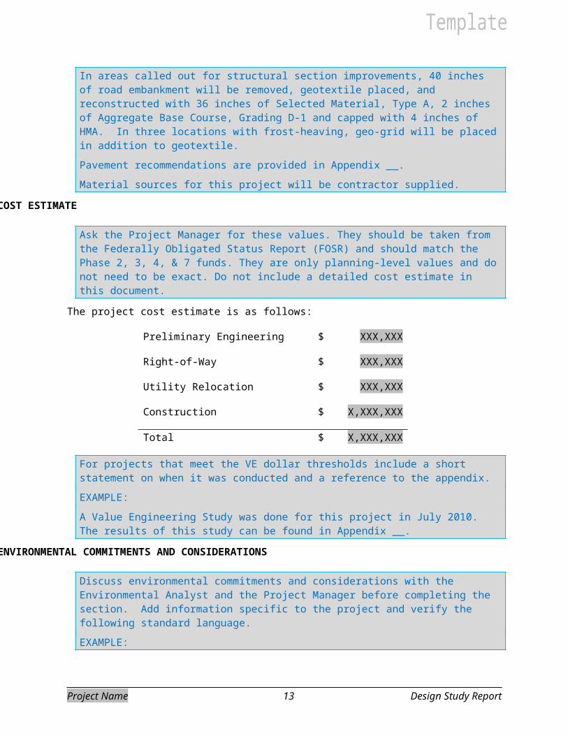
In areas called out for structural section improvements, 40 inches of road embankment will be removed, geotextile placed, and reconstructed with 36 inches of Selected Material, Type A, 2 inches of Aggregate Base Course, Grading D-1 and capped with 4 inches of HMA. In three locations with frost-heaving, geo-grid will be placed in addition to geotextile.
Pavement recommendations are provided in Appendix __.
Material sources for this project will be contractor supplied.
COST ESTIMATE
Ask the Project Manager for these values. They should be taken from the Federally Obligated Status Report (FOSR) and should match the Phase 2, 3, 4, & 7 funds. They are only planning-level values and do not need to be exact. Do not include a detailed cost estimate in this document.
The project cost estimate is as follows:
Preliminary Engineering $ XXX,XXX
Right-of-Way $ XXX,XXX
Utility Relocation $ XXX,XXX
Construction $ X,XXX,XXX
Total $ X,XXX,XXX
For projects that meet the VE dollar thresholds include a short statement on when it was conducted and a reference to the appendix.
EXAMPLE:
A Value Engineering Study was done for this project in July 2010. The results of this study can be found in Appendix __.
ENVIRONMENTAL COMMITMENTS AND CONSIDERATIONS
Discuss environmental commitments and considerations with the Environmental Analyst and the Project Manager before completing the section. Add information specific to the project and verify the following standard language.
EXAMPLE:
The proposed project does not involve any unusual circumstances or significant environmental impacts; it meets the criteria for classification as a Categorical Exclusion per 23 CFR 771.117. A Categorical Exclusion for the project was approved on DATE. A copy of the document is located in Appendix ___.
The contractor will be required to prepare and implement a SWPPP in accordance with Section 7.
Project Name 9 Design Study Report

The contractor will be required to dispose of solid waste at a DEC approved landfill. The contractor will be responsible for obtaining all necessary permits and clearances for materials sites, disposal sites, and staging areas unless DOT&PF has obtained all necessary permits.
BRIDGES
Use the statement below if it applies to your project.
No bridges are within the project limits.
EXCEPTIONS TO DESIGN STANDARDS
Use the statement below if it applies to your project.
There are no exceptions to design standards for this project.
MAINTENANCE CONSIDERATIONS
Discuss who will be responsible for maintenance of the features within the project. This may include the roadway, pedestrian facilities, or drainage features. Also discuss additional maintenance that will be required as a part of the project.
Maintenance will remain the responsibility of the State of Alaska and the local DOT&PF Maintenance and Operations Station located at ______________.
The project will increase maintenance efforts by ______________. Maintenance efforts will be reduced due to ______________.
ITS FEATURES
Discuss ITS elements to be incorporated into the project.
Project Name 10 Design Study Report

For All Appendices:
The signing of the DSR acts as Design Approval and must be distributed at the time of the signing.
Follow the process below for distribution:
Initial signing of DSR:
Distribute a copy of the signed DSR using the Final DSR Transmittal Memo (to FHWA, Central Files, etc.). Leave the original DSR unbound.
After Bid Opening (Beginning of Design Closeout):
If no significant design changes occurred after approval of DSR, replace the DSR in Central Files with the original DSR.
If significant design changes occur between the approval of this document and advertisement; the Project Engineer is responsible to complete a design memo (or memo to file) to supplement the Design Study Report. Use the DSR Revision Memo, http://www.dot.state.ak.us/creg/design/highways/Submittals/DSR/, to obtain approval. Insert memo(s) behind the cover sheet (treat it like an addendum) and redistribute the report using the Final DSR Transmittal Memo making sure the original DSR with revisions is filed in Central Files.
Examples of items added after signing of DSR:
* Design Exceptions & Waivers
* Final Pavement Recommendations
Project Name Design Study Report

APPENDIX A
Approved Design Criteria and Design Designation
Project Name Design Study Report

APPENDIX B
Typical Sections
Project Name Design Study Report

APPENDIX C
3R Analysis
If no additional Traffic Analysis was done, include one of the disclaimer statements from Appendix D here or in the 3R report.
Project Name Design Study Report

APPENDIX D
Traffic Analysis
Project Name Design Study Report

Items that may be included in this section, if not covered in another Appendix: Signal Warrants, Capacity Analysis, Roundabout Analysis, etc.
Choose one of the disclaimers below to include in the appendices prior to the traffic studies, which includes but is not limited to a capacity analysis and 3R analysis. This statement should be included in the body of the Traffic Analysis already and if so, does not need to be repeated.
Version 1:
The information in this report is compiled for highway safety planning purposes. Federal law prohibits its discovery or admissibility in litigation against state, tribal or local government that involves a location or locations mentioned in the collision data. 23 U.S.C. § 409; 23 U.S.C. § 148(g); Walden v. DOT, 27 P.3d 297, 304-305 (Alaska 2001).
Version 2:
The information in this report is compiled for highway safety planning purposes. Federal law prohibits its discovery or admissibility in litigation against state, tribal or local government that involves a location or locations mentioned in the collision data. 23 U.S.C. § 409; 23 U.S.C. § 148(g); Walden v. DOT, 27 P.3d 297, 304-305 (Alaska 2001). This compilation is derived from reports maintained by DMV, and DOT can make no representation about their accuracy.
Project Name Design Study Report

APPENDIX E
Material Recommendations
Project Name Design Study Report
APPENDIX F
VE Consideration
Project Name Design Study Report

APPENDIX G
Approved Environmental Document
Do not include the Environmental Document’s appendices.
Project Name Design Study Report

APPENDIX H
Approved Design Exceptions and Design Waivers
Project Name Design Study Report

APPENDIX I
ITS Systems Engineering Analysis
or
FHWA Concurrence Documentation for
Non-Significant ITS Project Determinations
Project Name Design Study Report

APPENDIX J
Design Memos
Project Name Design Study Report
Design Memos may include: Drainage Inspection Memos, Guardrail Inspection Memos, etc.
If no design memos have been created for the project at time of signing, insert the text below. This will serve as a placeholder in the case of any significant design changes after initial approval.
For DSR distribution:
The original, unbound DSR will be kept with the DOT&PF Project Manager until project bid opening. If no significant design changes occurred between approval of the DSR and project bid opening, the Project Manager will bind the original DSR and place it in Central Files. If significant design changes occur between the approval of the DSR and the bid opening resulting in Design Memos being produced, the Project Manager will bind the original DSR with Design Memos and file it in Central Files.
At this time, no significant design changes were made after the approval of this document. The final as-built plans for this project will be available in Central Files within the Highway Design Section (4111 Aviation Avenue, Anchorage, AK 99502).
Project Name Design Study Report