state of florida school bus
TRANSCRIPT
THIS PAGE INTENTIONALLY LEFT BLANK
STATE OF FLORIDA SCHOOL BUS
SAFETY INSPECTION MANUAL
2017 Edition

THIS PAGE INTENTIONALLY LEFT BLANK
i
PREFACE
The purpose of this manual is to standardize safety inspection criteria for school bus inspectors, technicians, maintenance supervisors and transportation directors to ensure that maintenance personnel know which components to inspect, how to inspect each component, how to identify which items are in need of repair and which defects constitute an out-of-service condition. The Florida School Bus Safety Inspection form number (2017-IF), which is incorporated by reference in rule 6A-3.0171, Florida Administrative Code (F.A.C.), correlates inspection items with those found in this manual. A copy of form 2017-IF is found on page 173 of this manual and may also be obtained from the School Transportation Management Section, Department of Education, 325 West Gaines Street, Tallahassee, Florida 32399, at a cost not to exceed actual production and distribution cost.
This manual was prepared to clarify many of the issues pertaining to school bus safety inspections. This manual will not answer all technical questions and will not eliminate the need for trained personnel to exercise professional judgment. The emphasis of this manual is on “SAFETY,” which should be the foremost consideration when inspecting school buses in Florida.
Sources used in preparing this manual include Florida School Bus Specifications, National School Transportation Specifications and Procedures, Federal Motor Vehicle Safety Standards (FMVSS), manufacturers’ maintenance and shop service manuals, other states’ inspection standards and other industry standards for maintenance and repair procedures.
i

SPECIFICATIONS NOTES
1. The school district may upgrade school buses to current specifications and revise inspection procedures according to the applicable specifications.
2. Inspection procedures for pilot test items approved by the Florida Department of Education (FDOE) and the Florida Association for Pupil Transportation (FAPT) School Bus Specifications Subcommittee may not be covered in this manual. Please refer to the school bus manufacturer and/or the equipment suppliers for inspection procedures for these items.
3. All Florida specifications dates that appear in this manual correspond to the dates vehicles were ordered or to the procurement invitation to bid (ITB) under which vehicles were purchased. Actual production dates cannot always be used to determine applicable specifications due to lead-time between ordering and build dates.
4. All FMVSS dates listed in this manual refer to the chassis build date. Any public school bus not meeting all applicable FMVSS must be removed from service until all non-compliance items are corrected.
5. Section 1006.25, Florida Statutes (F.S.), requires that all school buses transporting public school students must meet applicable federal motor vehicle safety standards and other specifications as prescribed by rules of the State Board of Education.
NOTE:
The inspection form and manual were first approved by the FAPT, incorporated by reference, and made part of the F.A.C. in November 1994. All school transportation providers regulated under section 1006.22, F.S., and rule 6A-3.0171, F.A.C., shall implement this manual. Please send any comments regarding this manual to the following address:
FAPT School Bus Inspection Committee Attn: School Transportation Management Section
Florida Department of Education 325 West Gaines Street, Room 834 Tallahassee, Florida 32399-0400
ii
INSTRUCTIONS
This manual must be used in conjunction with the Florida School Bus Safety Inspection Form 2017-IF (page 173) when inspecting school buses as required by rule 6A-3.0171, F.A.C. Districts are encouraged to ensure that copies of all applicable Florida School Bus Specifications manuals are available for use by inspectors during their inspections. Instructions on proper use of the state inspection form and the Florida School Bus Safety Inspection Manual are as follows:
The Florida School Bus Safety Inspection Form
1. Heading
Fill in completely, including the local bus number, mileage, repair order number (RO#), date of inspection, chassis/body manufacturer, seating capacity, model year of bus and shop location (if district has more than one shop).
2. Status Code Indicators
a) A " " (check mark) indicates that the items inspected meet all requirements of this manual and are in proper working order.
b) An “X” denotes a type of defect that does not affect the safe operation of the bus. Repair the item prior to returning the bus to service (if in district policy) or put a note on the form and repair the item within a reasonable amount of time.
c) The letter “O” indicates safety-related defects. Repairs of this nature are required prior to placing the bus back in service.
3. Status Code Column
Place a status code indicator (, X or O) indicating the inspection results for each row in this column as each row is inspected. See page 175 for an inspection form with the examples described below:
a) Section A - Inside Bus, Item 2, “Registration and Insurance Card,” is okay; therefore, A. 2. Is marked with a check ().
b) Section B - Outside Bus, Item 2 is marked with an “X” for a nonfunctional clearance light. Identify the deficiency by placing a circle around the words “clearance light” and providing a brief description in the comments for B. 2.
c) Section D - Underneath Bus, Item 13, “Wheels and Tires” is marked with an “O” for R/F tire tread depth and low air pressure, which are both out-of-service conditions. Note how the deficiencies are correctly identified and the actual measurements are recorded in the provided space near the bottom of the form.
iii

4. Inspection Items Column
All items on the form are to be inspected. Items in bold print are the main areas to be inspected. All other items pertain to the main areas.
Example: “Section A-Inside Bus,” Item “1. Emergency Equipment” would cover such items to be inspected as the fire extinguisher, first aid kit, body fluid cleanup kit and roadside reflectors. Inspection procedures for A-1 are found in the inspection manual.
5. Comments Column
This column must indicate the nature of the problem with the item circled in the “Inspection Items” column. See example on page 175.
6. Technician’s Initials Column
The repairing technician or inspector is required to place his/her initials in the corresponding “Tech Initials” box to indicate the repairs are complete or use the “Tech Initials” box to reference a repair order number that documents and addresses the concern.
7. Section E, “Lubrication and Maintenance” is optional and provided for the district’s convenience.
8. The “Comments” space on the back page of the form may be used to provide additional information related to the inspection. When writing additional comments, the inspector should label each comment with the corresponding section and number. Document any deficiency not covered on the form in this space. See example on page 175.
9. Enter the tread depth and air pressure of each tire in the space provided at the bottom of the form. Measure the tread depth according to the procedures in this manual. Record the initial air pressure reading prior to any necessary adjustment.
10. The inspector must sign the inspection form to indicate the inspection is complete.
11. The “Inspector’s Certification Number” must be the FDOE-assigned number as shown on the inspector’s certificate.
12. “Service Manager’s Initials” and “Bus Returned to Service Date” are required to document the service manager’s approval to return the bus to service.
iv

Repair Order Example
1. Verify all repairs noted on the inspection form on a repair order, including complete parts information and labor descriptions (see example repair order on page 178).
2. The technician who makes the correction should initial the repair order in the “Tech Initials” box corresponding to the item corrected.
3. It is recommended that the inspection form and associated repair order be kept together in the vehicle record.
Manual
The Florida School Bus Safety Inspection Manual provides detailed information and instructions corresponding to the individual items listed on the state inspection form.
On the following pages, the subject matter is in the upper left-hand corner of each page by section and subsection, such as “Section A-Inside Bus,” then 1. Emergency Equipment. There are three columns on each page with the following headings, “Inspection Procedures,” “Repair (or note) if ” and “Out-of-service if.” The columns should be used as follows:
1. Inspection Procedures This column outlines the methods to inspect each component for presence, condition, operation, mounting and specifications.
2. Repair (or) note This column is for documenting non-safety related deficiencies found meeting the repair or note failure criteria. Repair items should be addressed within a reasonable period of time. A note item is okay currently, but may need repair soon.
3. Out-of-service This column describes deficiencies that, if found, would place the bus out-of-service. Repair out-of-service items prior to placing the bus back in service.
Role of the School Bus Safety Inspector
The role of the school bus safety inspector is to identify and document deficiencies on buses according to the procedures and criteria described within this manual. Results of those inspections are to be reviewed by the district service manager, who shall make the final determination regarding whether buses are safe or unsafe to operate, unless this authority has been specifically delegated to another individual.
v
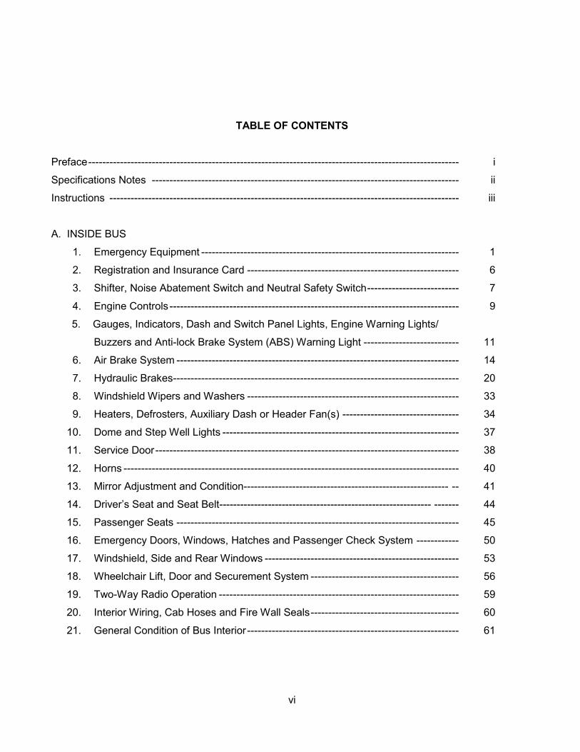
TABLE OF CONTENTS
Preface--------------------------------------------------------------------------------------------------------- i
Specifications Notes --------------------------------------------------------------------------------------- ii
Instructions --------------------------------------------------------------------------------------------------- iii
A. INSIDE BUS
1. Emergency Equipment ------------------------------------------------------------------------- 1
2. Registration and Insurance Card ------------------------------------------------------------ 6
3. Shifter, Noise Abatement Switch and Neutral Safety Switch-------------------------- 7
4. Engine Controls---------------------------------------------------------------------------------- 9
5. Gauges, Indicators, Dash and Switch Panel Lights, Engine Warning Lights/
Buzzers and Anti-lock Brake System (ABS) Warning Light --------------------------- 11
6. Air Brake System -------------------------------------------------------------------------------- 14
7. Hydraulic Brakes--------------------------------------------------------------------------------- 20
8. Windshield Wipers and Washers ------------------------------------------------------------ 33
9. Heaters, Defrosters, Auxiliary Dash or Header Fan(s) --------------------------------- 34
10. Dome and Step Well Lights ------------------------------------------------------------------- 37
11. Service Door-------------------------------------------------------------------------------------- 38
12. Horns ----------------------------------------------------------------------------------------------- 40
13. Mirror Adjustment and Condition----------------------------------------------------------- -- 41
14. Driver’s Seat and Seat Belt------------------------------------------------------------- ------- 44
15. Passenger Seats -------------------------------------------------------------------------------- 45
16. Emergency Doors, Windows, Hatches and Passenger Check System ------------ 50
17. Windshield, Side and Rear Windows ------------------------------------------------------- 53
18. Wheelchair Lift, Door and Securement System ------------------------------------------ 56
19. Two-Way Radio Operation -------------------------------------------------------------------- 59
20. Interior Wiring, Cab Hoses and Fire Wall Seals------------------------------------------ 60
21. General Condition of Bus Interior------------------------------------------------------------ 61
vi
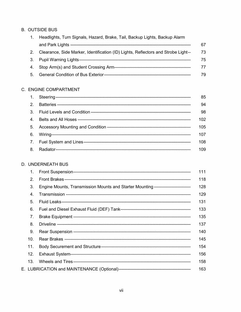
B. OUTSIDE BUS
1. Headlights, Turn Signals, Hazard, Brake, Tail, Backup Lights, Backup Alarm
and Park Lights ---------------------------------------------------------------------------------- 67
2. Clearance, Side Marker, Identification (ID) Lights, Reflectors and Strobe Light-- 73
3. Pupil Warning Lights---------------------------------------------------------------------------- 75
4. Stop Arm(s) and Student Crossing Arm---------------------------------------------------- 77
5. General Condition of Bus Exterior ----------------------------------------------------------- 79
C. ENGINE COMPARTMENT
1. Steering -------------------------------------------------------------------------------------------- 85
2. Batteries ------------------------------------------------------------------------------------------- 94
3. Fluid Levels and Condition -------------------------------------------------------------------- 98
4. Belts and All Hoses ----------------------------------------------------------------------------- 102
5. Accessory Mounting and Condition --------------------------------------------------------- 105
6. Wiring----------------------------------------------------------------------------------------------- 107
7. Fuel System and Lines------------------------------------------------------------------------- 108
8. Radiator-------------------------------------------------------------------------------------------- 109
D. UNDERNEATH BUS
1. Front Suspension-------------------------------------------------------------------------------- 111
2. Front Brakes -------------------------------------------------------------------------------------- 118
3. Engine Mounts, Transmission Mounts and Starter Mounting ------------------------- 128
4. Transmission ------------------------------------------------------------------------------------- 129
5. Fluid Leaks---------------------------------------------------------------------------------------- 131
6. Fuel and Diesel Exhaust Fluid (DEF) Tank------------------------------------------------ 133
7. Brake Equipment -------------------------------------------------------------------------------- 135
8. Driveline ------------------------------------------------------------------------------------------- 137
9. Rear Suspension -------------------------------------------------------------------------------- 140
10. Rear Brakes -------------------------------------------------------------------------------------- 145
11. Body Securement and Structure------------------------------------------------------------- 154
12. Exhaust System---------------------------------------------------------------------------------- 156
13. Wheels and Tires-------------------------------------------------------------------------------- 158
E. LUBRICATION and MAINTENANCE (Optional)------------------------------------------------- 163
vii

F. ROAD TEST
1. Brake Performance ----------------------------------------------------------------------------- 165
2. Engine, Transmission and Driveline -------------------------------------------------------- 167
3. Steering and Handling-------------------------------------------------------------------------- 168
Chart and Figure Contents -------------------------------------------------------------------------------- 171
Statutory Requirement for Safe Transportation of Students -------------------------------------- 172
State Board of Education Rule on School District Responsibilities for the Safe
Transportation of Students------------------------------------------------------------------------------ --- 172
Florida School Bus Safety Inspection Form ---------------------------------------------------------- 173
Florida School Bus Safety Inspection Form, example ---------------------------------------------- 175
Repair Order -------------------------------------------------------------------------------------------------- 177
Repair Order, example ------------------------------------------------------------------------------------ 178
School Bus Safety Inspection Certification Program ------------------------------------------------ 179
School Bus Safety Inspection Recertification Program--------------------------------------------- 183
District Online Test Administrator Guidelines and Requirements--------------------------------- 185
District Online Test Administrator Application--------------------------------------------------------- 186
State of Florida, School Bus Safety Inspector Application------------------------------------------- 187
2017 Table of Changes -------------------------------------------------------------------------------------- 189
viii

A. INSIDE BUS
1. Emergency Equipment
Inspection Procedures: Repair (or note) if: Out-of-Service if:
a. Fire Extinguisher
Check for the presence of a fire extinguisher and for the following:
1) Pressure: Check gauge.
2) Tag (Inspection Date): Check for the presence of inspection sticker or tag and inspection date.
3) Mounting: Check for accessibility and secure mounting.
Inspection sticker or tag will expire before next scheduled inspection.
Bracket mount is loose.
No fire extinguisher is on bus.
Pressure is above or below the green zone.
Tag or sticker is missing or does not verify inspection was performed within the previous twelve months. Exception: Buses less than one year old with original fire extinguisher do not need a tag or sticker.
Fire extinguisher is not accessible to driver, not mounted securely or mounted in a lockable compartment not equipped with an operational ignition-warning buzzer or interlock.
4) Rating: Check for proper Underwriters Laboratory (UL) rating.
Rating is less than 2A-10BC.
(Continued on Next Page)
1

A. INSIDE BUS 1. Emergency Equipment
Inspection Procedures: Repair (or note) if: Out-of-Service if:
5) Nozzle/hose: Check for loose or damaged parts.
6) Safety Pin: Check for presence of safety pin and breakable, non-reusable tamper seal.
b. First Aid Kit
1) Kit box and condition: Buses built since 1985 require a moisture and dust-proof kit box with a clear lid.
Check for the presence of a breakable, non-reusable tamper seal for buses built since September 1995.
2) Mounting: Check accessibility and mounting of kit. Kit should be mounted in the driver’s area in such a manner that it can be easily detached and made portable.
Tamper seal is broken, missing or reusable (can be opened and resealed without destroying the seal).
NOTE: Must check kit contents if seal is broken or missing (also see the NOTE on page 3).
Hose or nozzle is loose, missing or there is excessive damage to any part of the extinguisher.
Safety pin is missing and/or tamper seal is broken.
Tamper seal cannot be broken or seal is reusable (can be opened and resealed without destroying the seal).
Kit is not present; kit box is not moisture- proof and dust-proof, will not stay latched, cannot be opened or is not equipped with a clear lid.
Tamper seal cannot be broken.
Kit is not secured, not mounted in the driver's compartment, not easily detached or mounted in a lockable compartment not equipped with an operational ignition-warning buzzer or interlock.
(Continued on Page 4)
2

CHART 1a: BODY FLUID CLEANUP KIT CHART 1: FIRST AID KITS
BUSES MANUFACTURED FROM 1985 TO PRESENT
DESCRIPTION QUANTITY 1” bandage compress (e.g., Band-Aid) 2 pkgs. 40” triangular bandage with two safety pins 1 pkg.
4” X 4” sterile gauze pads 6 pkgs.
of 2 each 2” rolled curlex bandages 6 yards in length 1 pkg. 1” roll adhesive tape 2-1/2 yards in length 1 roll Eye dressing packet 2 pkgs.
DESCRIPTION QUANTITY An Environmental Protection Agency (EPA)-registered germicide (tuberculocidal) disinfectant 1 A fully disposable wiping cloth 1 A water-resistant spatula 1 Step-by-step directions 1 Odor-counteracting absorbent material 1 Latex gloves 2 pairs Towelettes 1 pkg. A discard bag (non-labeled paper bag with plastic liner and twist tie). This bag shall be approximately 4” x 6” x 14” and be of a non-safety color (i.e., not red, orange or yellow). 1
Note: In addition to scheduled inspections, all first aid and body fluid cleanup kits should be opened and inspected annually to check the condition and presence of contents according to A 1. b. & c.
3
A. INSIDE BUS 1. Emergency Equipment
Inspection Procedures: Repair (or note) if: Out-of-Service if:
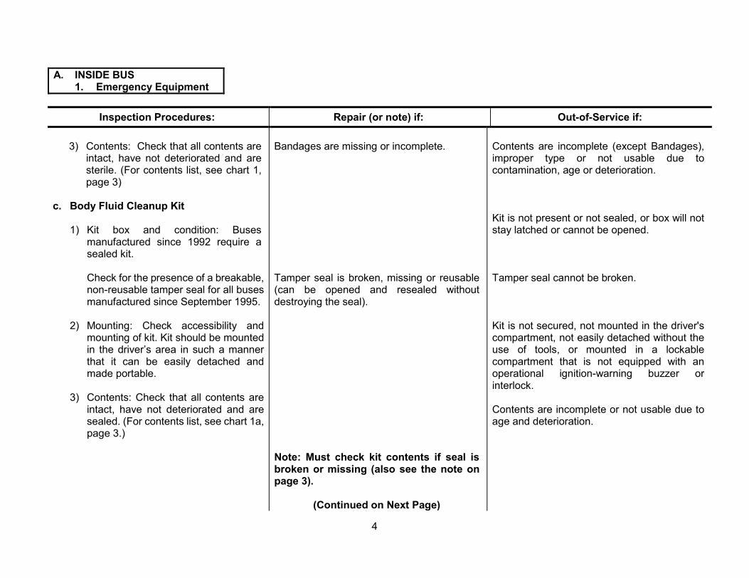
c.
3) Contents: Check that all contents are intact, have not deteriorated and are sterile. (For contents list, see chart 1, page 3)
Body Fluid Cleanup Kit
1) Kit box and condition: Buses manufactured since 1992 require a sealed kit.
Check for the presence of a breakable, non-reusable tamper seal for all buses manufactured since September 1995.
2) Mounting: Check accessibility and mounting of kit. Kit should be mounted in the driver’s area in such a manner that it can be easily detached and made portable.
3) Contents: Check that all contents are intact, have not deteriorated and are sealed. (For contents list, see chart 1a, page 3.)
Bandages are missing or incomplete.
Tamper seal is broken, missing or reusable (can be opened and resealed without destroying the seal).
Note: Must check kit contents if seal is broken or missing (also see the note on page 3).
(Continued on Next Page)
Contents are incomplete (except Bandages), improper type or not usable due to contamination, age or deterioration.
Kit is not present or not sealed, or box will not stay latched or cannot be opened.
Tamper seal cannot be broken.
Kit is not secured, not mounted in the driver's compartment, not easily detached without the use of tools, or mounted in a lockable compartment that is not equipped with an operational ignition-warning buzzer or interlock.
Contents are incomplete or not usable due to age and deterioration.
4

A. INSIDE BUS 1. Emergency Equipment
Inspection Procedures: d. Reflectors
1) Check for proper quantity, type and condition of emergency roadside reflectors.
2) Check accessibility, mounting and condition of box. Must be securely mounted in driver’s area.
3) Check for the presence of a breakable, non-reusable tamper seal for buses manufactured since September 1995.
Repair (or note) if:
Tamper seal is broken, missing or reusable (can be opened and resealed without destroying the seal).
Out-of-Service if:
Not equipped with three self-standing, 17-inch triangular reflectors or any of the reflectors, or box is unusable due to age, damage or deterioration.
Storage box is broken, will not remain latched, is not easily accessible, is not securely mounted forward of the passenger compartment, or mounted in a lockable compartment, or is not equipped with an operational ignition warning buzzer or inter-lock.
Tamper seal cannot be broken.
5
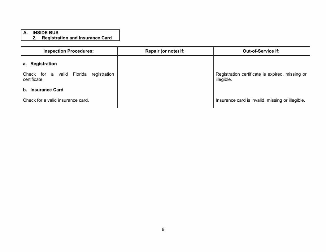
A. INSIDE BUS 2. Registration and Insurance Card
Inspection Procedures:
a. Registration
Check for a valid Florida registration certificate.
b. Insurance Card
Check for a valid insurance card.
Repair (or note) if: Out-of-Service if:
Registration certificate is expired, missing or illegible.
Insurance card is invalid, missing or illegible.
6
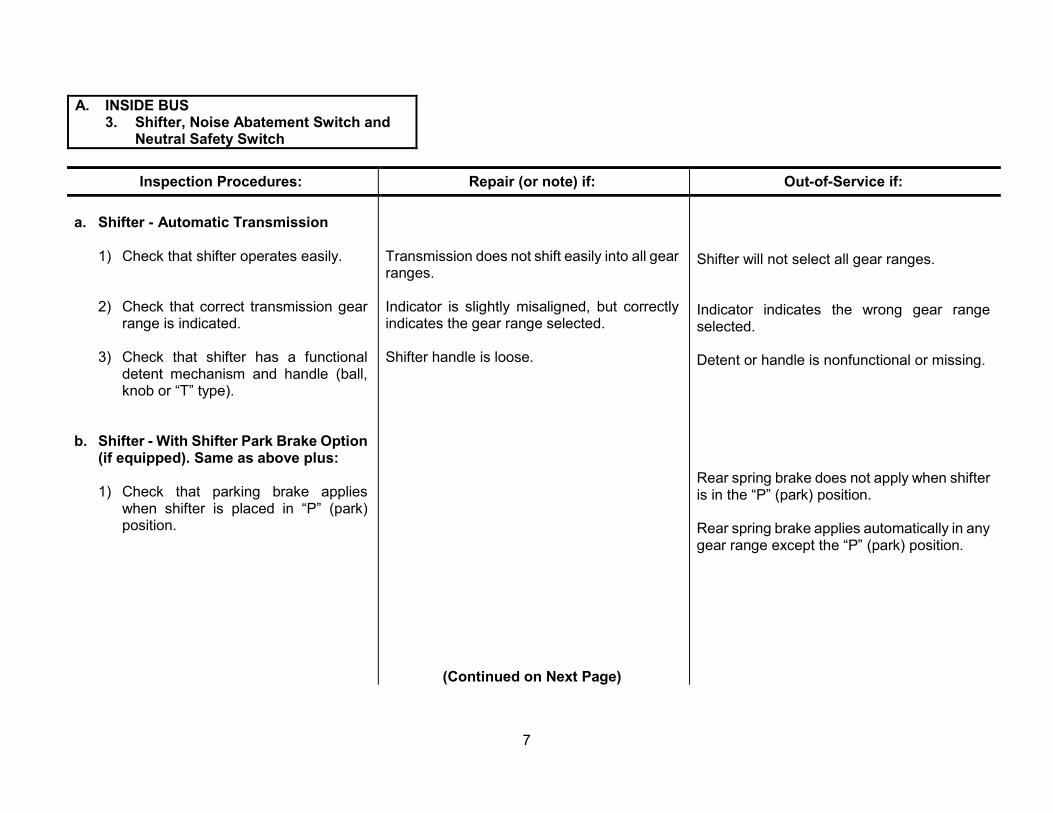
A. INSIDE BUS 3. Shifter, Noise Abatement Switch and
Neutral Safety Switch
Inspection Procedures: Repair (or note) if: Out-of-Service if:
a. Shifter - Automatic Transmission
1) Check that shifter operates easily.
2) Check that correct transmission gear range is indicated.
3) Check that shifter has a functional detent mechanism and handle (ball, knob or “T” type).
Transmission does not shift easily into all gear ranges.
Indicator is slightly misaligned, but correctly indicates the gear range selected.
Shifter handle is loose.
Shifter will not select all gear ranges.
Indicator indicates the wrong gear range selected.
Detent or handle is nonfunctional or missing.
b. Shifter - With Shifter Park Brake Option (if equipped). Same as above plus:
1) Check that parking brake applies when shifter is placed in “P” (park) position.
Rear spring brake does not apply when shifter is in the “P” (park) position.
Rear spring brake applies automatically in any gear range except the “P” (park) position.
(Continued on Next Page)
7

A. INSIDE BUS 3. Shifter, Noise Abatement Switch and
Neutral Safety Switch
Inspection Procedures: Repair (or note) if: Out-of-Service if:
c. Noise Abatement Switch (Required on buses manufactured since 2002)
Inspect for proper operation. Switch must deactivate all non-safety-essential noise-making equipment.
Switch is not clearly labeled or not of an alternate color.
Switch/System does not work or does not deactivate required items such as AM/FM radio and CD player, heaters, defrosters, fans and air conditioners.
d. Neutral Safety Switch
Check to determine that automatic transmission bus has a functional neutral safety switch that will allow the starter to operate only in park or neutral.
Switch/System deactivates safety-essential items such as windshield wipers and lighting systems.
The starter will engage when automatic transmission is in any gear other than park or neutral.
8
A. INSIDE BUS 4. Engine Controls
Inspection Procedures: Repair (or note) if: Out-of-Service if:
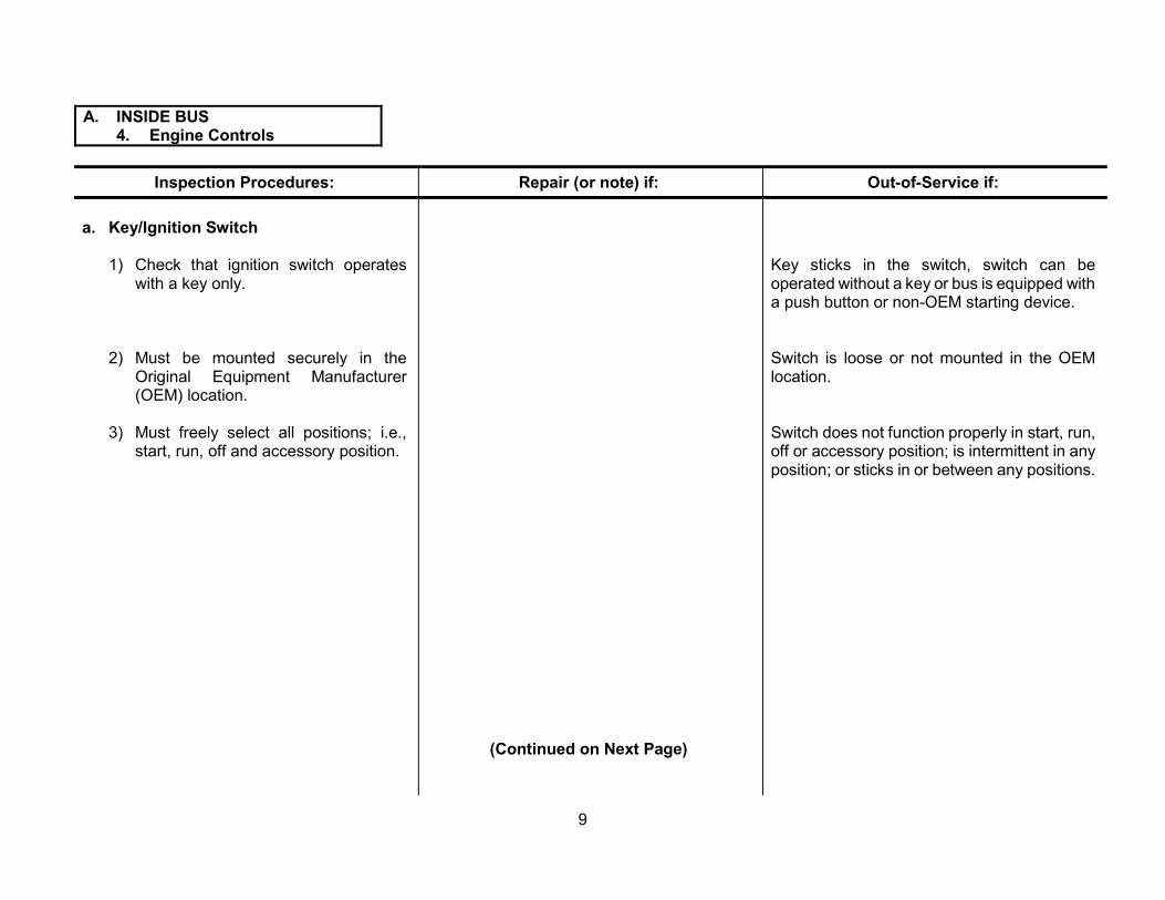
a. Key/Ignition Switch
1) Check that ignition switch operates with a key only.
2) Must be mounted securely in the Original Equipment Manufacturer (OEM) location.
3) Must freely select all positions; i.e., start, run, off and accessory position.
(Continued on Next Page)
Key sticks in the switch, switch can be operated without a key or bus is equipped with a push button or non-OEM starting device.
Switch is loose or not mounted in the OEM location.
Switch does not function properly in start, run, off or accessory position; is intermittent in any position; or sticks in or between any positions.
9

A. INSIDE BUS 4. Engine Controls
Inspection Procedures: Repair (or note) if: Out-of-Service if:
b. Accelerator
1) Check condition of pedal assembly, mounting and securement.
2) Inspect pedal assembly, wiring, connectors and linkage for condition and loose or missing hardware. Mechanical linkage type must have dual (two) return springs.
3) Check for smooth operation of pedal assembly and linkage in the accelerating and coast position.
Pedal cover worn but not causing a slippery pedal condition.
Pedal cover is worn badly or missing. Pedal assembly is modified or not mounted securely in the OEM location.
Pedal assembly is not operating properly; wiring is loose, damaged or improperly routed; hardware is loose or missing; or mechanical type linkage is loose, damaged or not equipped with dual return springs.
Accelerator control and/or linkage sticks or does not operate freely.
10

A. INSIDE BUS 5. Gauges, Indicators, Dash and Switch
Panel Lights, Engine Warning Lights/Buzzers and ABS Warning Light
Inspection Procedures: Repair (or note) if: Out-of-Service if:
a. Gauges
From the driver’s position, check the visibility, OEM location, readability, operation, accuracy and condition of the following gauges:
1) Speedometer and odometer
2) Engine oil pressure, temperature and transmission temperature
3) Fuel
4) Voltmeter or ammeter
Odometer is unreadable, does not work or is not working properly.
Oil pressure or temperature gauge is inaccurate or difficult to read.
Fuel gauge is inaccurate or difficult to read.
Voltmeter or ammeter is inaccurate, damaged or difficult to read.
Speedometer is unreadable, damaged, does not function or is confirmed to be inaccurate.
Oil pressure or engine and transmission temperature gauge is unreadable, damaged or does not function.
Fuel gauge is unreadable, damaged or does not function.
Voltmeter or ammeter does not work or does not indicate that alternator is charging. Refer to C-5, f. on page 106.
11
A. INSIDE BUS 5. Gauges, Indicators, Dash and Switch
Panel Lights, Engine Warning Lights/Buzzers and ABS Warning Light
Inspection Procedures: Repair (or note) if: Out-of-Service if:
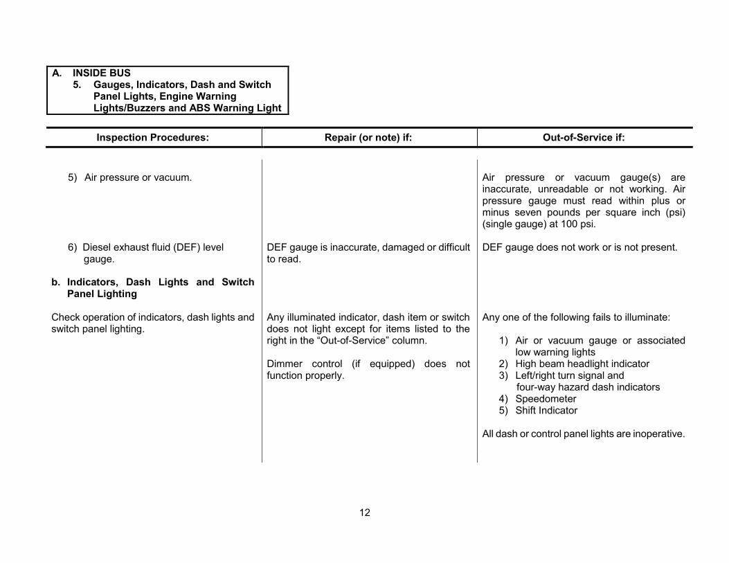
5) Air pressure or vacuum.
6) Diesel exhaust fluid (DEF) level DEF gauge is inaccurate, damaged or difficult gauge. to read.
b. Indicators, Dash Lights and Switch Panel Lighting
Check operation of indicators, dash lights and Any illuminated indicator, dash item or switch switch panel lighting. does not light except for items listed to the
right in the “Out-of-Service” column.
Dimmer control (if equipped) does not function properly.
Air pressure or vacuum gauge(s) are inaccurate, unreadable or not working. Air pressure gauge must read within plus or minus seven pounds per square inch (psi) (single gauge) at 100 psi.
DEF gauge does not work or is not present.
Any one of the following fails to illuminate:
1) Air or vacuum gauge or associated low warning lights
2) High beam headlight indicator 3) Left/right turn signal and
four-way hazard dash indicators 4) Speedometer 5) Shift Indicator
All dash or control panel lights are inoperative.
12

A. INSIDE BUS 5. Gauges, Indicators, Dash and Switch
Panel Lights, Engine Warning Lights/Buzzers and ABS Warning Light
Inspection Procedures:
c. Engine/Transmission Warning Lights and Buzzer
Check for presence and operation of the following warning lights and audible alarms:
1) High coolant temperature dash warning light and alarm on diesel buses
2) High transmission temperature dash warning light and alarm
3) Low oil pressure, dash warning light and alarm on diesel buses
d. ABS Warning Light
Check condition of ABS warning lamp and system (if equipped). Refer to applicable vehicle technical publication for test procedures and diagnostic information.
Repair (or note) if: Out-of-Service if:
High coolant temperature dash warning light and/or alarm is inoperative.
Transmission high temperature light and/or alarm is inoperative.
Low oil pressure, dash warning light and/or alarm is inoperative.
Any of the above lights are on, indicating a critical mechanical condition.
Lamp fails to turn on during initial startup sequence.
Lamp fails to turn off.
System fails to operate per manufacturer's specifications.
13

A. INSIDE BUS 6. Air Brake System
Note: Chock bus wheels when inspection procedures require the service, parking and/or emergency brakes to be in the released position.
Inspection Procedures: Repair (or note) if: Out-of-Service if:
a. Gauge(s)
Check for presence of two air pressure Any gauge is missing or unreadable. Gauge gauges or a single gauge with dual needles. is not accurate to within plus or minus 7 One gauge or needle should indicate air percent. Any gauge is not in OEM location. pressure available to the front air brake More than 15-psi difference in dual air brake system, and the other should indicate air system (dual gauges) with system built up to pressure available to the rear air brake full pressure (100-125 psi). system. Both gauges must be accurate to within plus or minus seven psi.
b. Buildup
Drain air reservoir thoroughly before making Air pressure buildup time from 85 to 100 psi at this check. Check the time required for air fast idle is greater than 40 seconds. pressure to build up from 85 to 100 psi with engine at approximately 1,200 RPM.
Note: If air brake gauge(s) failed inspection step a. of this section, make necessary repairs prior to performing the test in step b.
(Continued on Next Page)
14

A. INSIDE BUS 6. Air Brake System
Inspection Procedures: Repair (or note) if: Out-of-Service if:
c. Governor
Check air brake system governor operation. While building up system air pressure, note pressure at which governor cuts out (compressor quits compressing). With engine still running, pump brakes to lower air pressure until compressor cuts in (starts compressing again). Note pressure.
Note: If gauge(s) failed previous check for accuracy, do not perform this check until gauge(s) are repaired.
d. Park/Emergency Brake
Check condition, mounting and location of park/emergency brake valve, proper release and application of park/emergency brake and interlock(s) operation (if equipped).
With parking/emergency brake applied and service brake released, apply engine torque by placing transmission selector in “Drive” (D) and briefly accelerate the engine to approximately 1,200 revolutions per minute (RPM); vehicle should not move forward.
Cut-out pressure is below 120 psi (for buses equipped with air dryer).
Cut-out pressure is too low (below 100 psi) or too high (above 130 psi).
Difference between governor cut-out and cut-in pressure exceeds 30 psi.
Valve labeling is missing or unreadable. Valve not mounted securely in original position; knob is missing, broken or cracked; park/emergency brake does not release and/or apply properly; or interlock(s) (if equipped) do not function properly.
NOTE: If a bus is equipped with a rear diesel engine and an Allison World transmission, perform this test at 900 RPM.
Vehicle moves forward upon applying engine torque with park/emergency brake applied and service brake released.
(Continued on Next Page)
15
A. INSIDE BUS 6. Air Brake System
Inspection Procedures: Repair (or note) if: Out-of-Service if:
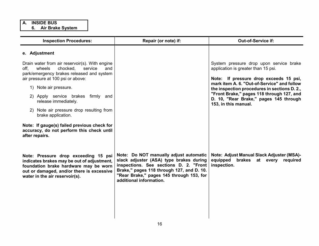
e. Adjustment
Drain water from air reservoir(s). With engine off, wheels chocked, service and park/emergency brakes released and system air pressure at 100 psi or above:
1) Note air pressure.
2) Apply service brakes firmly and release immediately.
2) Note air pressure drop resulting from brake application.
Note: If gauge(s) failed previous check for accuracy, do not perform this check until after repairs.
Note: Pressure drop exceeding 15 psi indicates brakes may be out of adjustment, foundation brake hardware may be worn out or damaged, and/or there is excessive water in the air reservoir(s).
Note: Do NOT manually adjust automatic slack adjuster (ASA) type brakes during inspections. See sections D. 2. "Front Brake," pages 118 through 127, and D. 10. "Rear Brake," pages 145 through 153, for additional information.
System pressure drop upon service brake application is greater than 15 psi.
Note: If pressure drop exceeds 15 psi, mark item A. 6. "Out-of-Service" and follow the inspection procedures in sections D. 2., "Front Brake," pages 118 through 127, and D. 10, "Rear Brake," pages 145 through 153, in this manual.
Note: Adjust Manual Slack Adjuster (MSA)-equipped brakes at every required inspection.
16
A. INSIDE BUS 6. Air Brake System
Inspection Procedures: Repair (or note) if: Out-of-Service if:
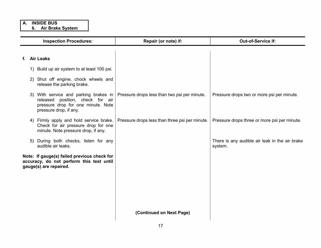
f. Air Leaks
1) Build up air system to at least 100 psi.
2) Shut off engine, chock wheels and release the parking brake.
3) With service and parking brakes in released position, check for air pressure drop for one minute. Note pressure drop, if any.
4) Firmly apply and hold service brake. Check for air pressure drop for one minute. Note pressure drop, if any.
5) During both checks, listen for any audible air leaks.
Note: If gauge(s) failed previous check for accuracy, do not perform this test until gauge(s) are repaired.
Pressure drops less than two psi per minute. Pressure drops two or more psi per minute.
Pressure drops less than three psi per minute. Pressure drops three or more psi per minute.
There is any audible air leak in the air brake system.
(Continued on Next Page)
17
A. INSIDE BUS 6. Air Brake System
Inspection Procedures: Repair (or note) if: Out-of-Service if:
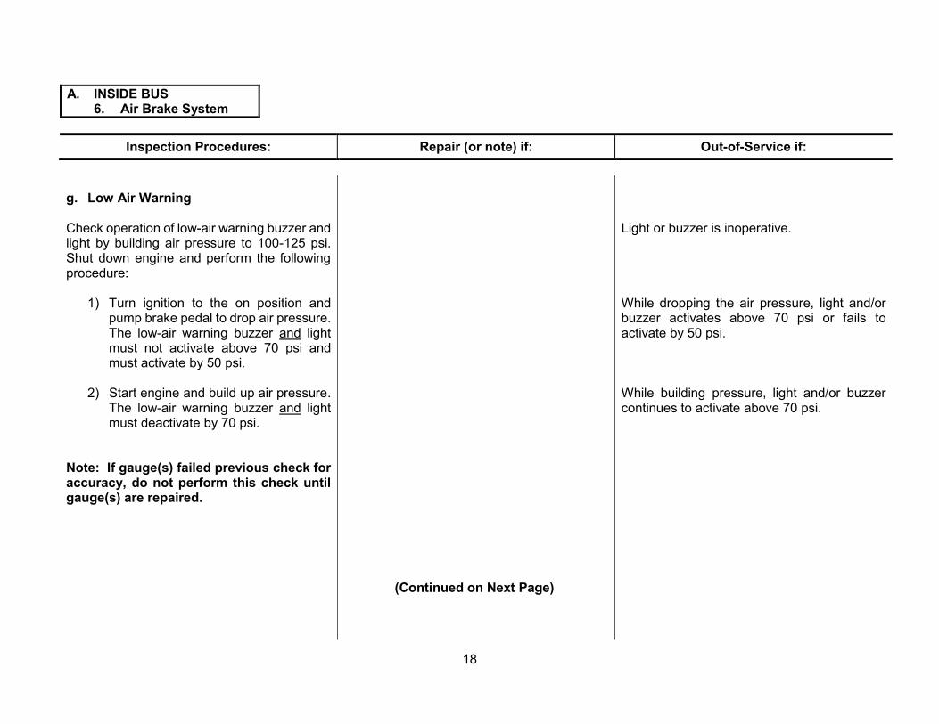
g. Low Air Warning
Check operation of low-air warning buzzer and light by building air pressure to 100-125 psi. Shut down engine and perform the following procedure:
1) Turn ignition to the on position and pump brake pedal to drop air pressure. The low-air warning buzzer and light must not activate above 70 psi and must activate by 50 psi.
2) Start engine and build up air pressure. The low-air warning buzzer and light must deactivate by 70 psi.
Note: If gauge(s) failed previous check for accuracy, do not perform this check until gauge(s) are repaired.
Light or buzzer is inoperative.
While dropping the air pressure, light and/or buzzer activates above 70 psi or fails to activate by 50 psi.
While building pressure, light and/or buzzer continues to activate above 70 psi.
(Continued on Next Page)
18
A. INSIDE BUS 6. Air Brake System
Inspection Procedures: Repair (or note) if: Out-of-Service if:
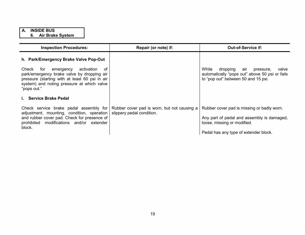
h. Park/Emergency Brake Valve Pop-Out
Check for emergency activation of park/emergency brake valve by dropping air pressure (starting with at least 60 psi in air system) and noting pressure at which valve “pops out.”
i. Service Brake Pedal
Check service brake pedal assembly for adjustment, mounting, condition, operation and rubber cover pad. Check for presence of prohibited modifications and/or extender block.
Rubber cover pad is worn, but not causing a slippery pedal condition.
While dropping air pressure, valve automatically “pops out” above 50 psi or fails to “pop out” between 50 and 15 psi.
Rubber cover pad is missing or badly worn.
Any part of pedal and assembly is damaged, loose, missing or modified.
Pedal has any type of extender block.
19

A. INSIDE BUS 7. Hydraulic Brakes
Note: Several inspection procedures outlined in this manual require the service, parking and/or emergency brakes in the released position. When performing these checks, bus wheels must be chocked to prevent the bus from moving.
Inspection Procedures: Repair (or note) if: Out-of-Service if:
Note: If bus is not equipped with hydraulic brakes, proceed to page 33.
Note: See page 131 for definitions of fluid “leaks” and “seepage.”
Since there are four distinct types of hydraulic brake systems in use on Florida school buses, this manual will cover each system individually. It is imperative that you know the type of system you will be inspecting to ensure that the proper inspection procedure is used.
The four types of systems are: a. Standard Vacuum Assisted Hydraulic Brakes. (See page 21) b. Hydraulic Power Assisted Hydraulic Brake with Accumulator Backup. (See page 24) c. Hydraulic Power Assisted Hydraulic Brakes with Electric Pump Backup and Driveshaft Parking Brake Systems. (See page 27) d. Hydraulic Power Assisted Hydraulic Brakes with Spring Set (hydraulically released) Parking Brakes (Ford Maxi-brake(s)). (See page 29)
(Continued on Next Page)
20

A. INSIDE BUS 7. Hydraulic Brakes
Inspection Procedures: Repair (or note) if: Out-of-Service if:
a. Standard Vacuum Assisted Hydraulic Brakes. Inspect for:
1) Any visible seepage or leaks in the hydraulic brake system.
2) a) Brake pedal reserve (distance from floor) upon firm brake application (engine running).
b) Brake pedal fade (pedal falls to floor when held down with engine running and with engine off) indicating brake system leak.
3) a) Vacuum gauge operation (if equipped) and low vacuum indicator light and buzzer (if equipped) with full vacuum below eight inches of mercury (hg).
NOTE: See page 131 for definitions of fluid “leaks” and “seepage.”
Any seepage or leaks are found.
Brake pedal (reserve) is less than one inch from floor.
Any brake pedal fade is felt.
Vacuum gauge (if equipped) is inoperative, inaccurate or not clearly visible.
Low vacuum indicator light and buzzer do not come on below eight inches of mercury (hg).
(Continued on Next Page)
21
A. INSIDE BUS 7. Hydraulic Brakes
Inspection Procedures:
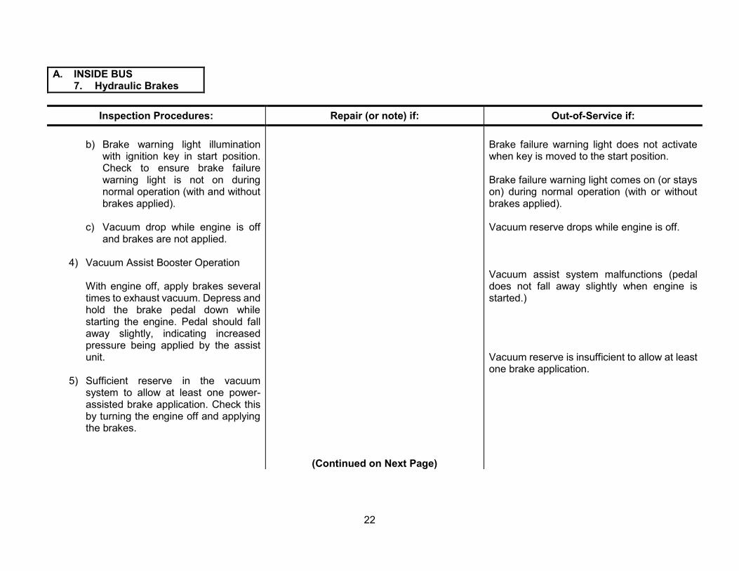
b) Brake warning light illumination with ignition key in start position. Check to ensure brake failure warning light is not on during normal operation (with and without brakes applied).
c) Vacuum drop while engine is off and brakes are not applied.
4) Vacuum Assist Booster Operation
With engine off, apply brakes several times to exhaust vacuum. Depress and hold the brake pedal down while starting the engine. Pedal should fall away slightly, indicating increased pressure being applied by the assist unit.
5) Sufficient reserve in the vacuum system to allow at least one power-assisted brake application. Check this by turning the engine off and applying the brakes.
Repair (or note) if:
(Continued on Next Page)
Out-of-Service if:
Brake failure warning light does not activate when key is moved to the start position.
Brake failure warning light comes on (or stays on) during normal operation (with or without brakes applied).
Vacuum reserve drops while engine is off.
Vacuum assist system malfunctions (pedal does not fall away slightly when engine is started.)
Vacuum reserve is insufficient to allow at least one brake application.
22

A. INSIDE BUS 7. Hydraulic Brakes
Inspection Procedures: Repair (or note) if: Out-of-Service if:
6) All brake hardware components inside bus for secure mounting, routing and condition, including:
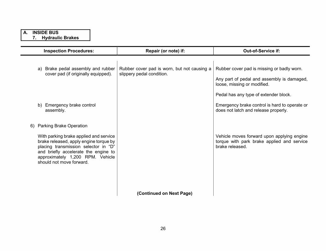
a) Brake pedal assembly and rubber cover (if originally equipped).
b) Emergency brake control assembly.
7) Parking Brake Operation
With parking brake applied and service brake released, apply engine torque by placing transmission selector in “D” and briefly accelerate the engine to approximately 1,200 RPM. Vehicle should not move forward.
Rubber cover is worn, but not causing a slippery pedal condition.
Brake pedal assembly, push rod and clevis or emergency brake control assembly is insecurely mounted; poorly routed; has loose, missing or worn hardware; or is damaged.
Rubber cover pad is missing or badly worn.
Any part of pedal and assembly is damaged, loose, missing or modified.
Pedal has any type of extender block.
Emergency brake control is hard to operate or does not latch and release properly.
Vehicle moves forward upon applying engine torque with park brake applied and service brake released.
23

A. INSIDE BUS 7. Hydraulic Brakes
Inspection Procedures: Repair (or note) if: Out-of-Service if:
b. Hydraulic Power Assisted Hydraulic Brakes with Accumulator Backup. Inspect for:
1) Visible seepage or leaks in the brake or hydraulic assist systems.
2) a) Brake pedal reserve (distance from floor) upon one firm brake application (engine off, accumulator depleted).
b) Brake pedal fade (test for at least one and a half minutes with the engine off). Firmly apply brake pedal and hold.
3) Brake warning light illumination with ignition key in start position. Check to ensure brake failure warning light is not on during normal operation (with and without brakes applied).
Note: See page 131 for definitions of fluid “leaks” and “seepage.”
Any brake or hydraulic assist fluid is seeping or leaking.
Brake pedal does not have at least a one and a half inch of reserve distance from floor.
Pedal falls to floor (fades) when held down (engine off), indicating a brake system leak.
Brake failure warning light does not activate when key is turned to the start position or stays on during normal operation.
(Continued on Next Page)
24
A. INSIDE BUS 7. Hydraulic Brakes
Inspection Procedures:
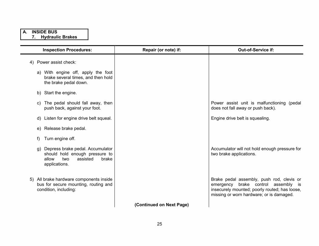
4) Power assist check:
a) With engine off, apply the foot brake several times, and then hold the brake pedal down.
b) Start the engine.
c) The pedal should fall away, then push back, against your foot.
d) Listen for engine drive belt squeal.
e) Release brake pedal.
f) Turn engine off.
g) Depress brake pedal. Accumulator should hold enough pressure to allow two assisted brake applications.
5) All brake hardware components inside bus for secure mounting, routing and condition, including:
Repair (or note) if:
(Continued on Next Page)
Out-of-Service if:
Power assist unit is malfunctioning (pedal does not fall away or push back).
Engine drive belt is squealing.
Accumulator will not hold enough pressure for two brake applications.
Brake pedal assembly, push rod, clevis or emergency brake control assembly is insecurely mounted; poorly routed; has loose, missing or worn hardware; or is damaged.
25
A. INSIDE BUS 7. Hydraulic Brakes
Inspection Procedures: Repair (or note) if: Out-of-Service if:
a) Brake pedal assembly and rubber cover pad (if originally equipped).
Rubber cover pad is worn, but not causing a slippery pedal condition.
b) Emergency brake control assembly.
6) Parking Brake Operation
With parking brake applied and service brake released, apply engine torque by placing transmission selector in “D” and briefly accelerate the engine to approximately 1,200 RPM. Vehicle should not move forward.
(Continued on Next Page)
Rubber cover pad is missing or badly worn.
Any part of pedal and assembly is damaged, loose, missing or modified.
Pedal has any type of extender block.
Emergency brake control is hard to operate or does not latch and release properly.
Vehicle moves forward upon applying engine torque with park brake applied and service brake released.
26

A. INSIDE BUS 7. Hydraulic Brakes
Inspection Procedures: Repair (or note) if: Out-of-Service if:
c. Hydraulic Power Assisted Hydraulic Brakes with electric pump backup and driveshaft parking brake system. Inspect for:
1) Visible seepage or leaks in the brake or hydraulic assist system.
2) Brake warning and backup systems using the appropriate chassis manufacturer’s procedure in chart 2, page 31.
3) a) Brake pedal distance from floor (reserve) upon one firm brake application with engine off and hydraulic boost depleted.
b) Brake pedal fade (continues to fall to floor after initial firm application) with engine off.
6) All brake hardware components inside bus for secure mounting, routing and condition, including:
NOTE: See page 131 for definitions of fluid “leaks” and “seepage.”
Any brake or hydraulic assist fluid is seeping or leaking.
The brake system does not pass all tests in chart 2, page 31.
Brake pedal reserve is less than one inch from floor.
Any brake pedal fade is felt.
(Continued on Next Page)
Brake pedal assembly, push rod, clevis or emergency brake control assembly is insecurely mounted; poorly routed; has loose, missing or worn hardware; or is damaged.
27

A. INSIDE BUS 7. Hydraulic Brakes
Inspection Procedures: Repair (or note) if: Out-of-Service if:
a) Brake pedal assembly and rubber cover pad (if originally equipped).
Rubber cover pad is worn, but not causing a slippery pedal condition.
Rubber cover pad is missing or badly worn.
Any part of pedal and assembly is damaged, loose, missing or modified.
Pedal has any type of extender block.
b) Emergency brake control assembly.
Emergency brake control is hard to operate or does not latch and release properly.
5) Parking Brake Operation
With parking brake applied and service brake released, apply engine torque by placing transmission selector in “D” and briefly accelerate the engine to approximately 1,200 RPM. Vehicle should not move forward.
Vehicle moves forward upon applying engine torque with park brake applied and service brake released.
(Continued on Next Page)
28
A. INSIDE BUS 7. Hydraulic Brakes
Inspection Procedures: Repair (or note) if: Out-of-Service if:
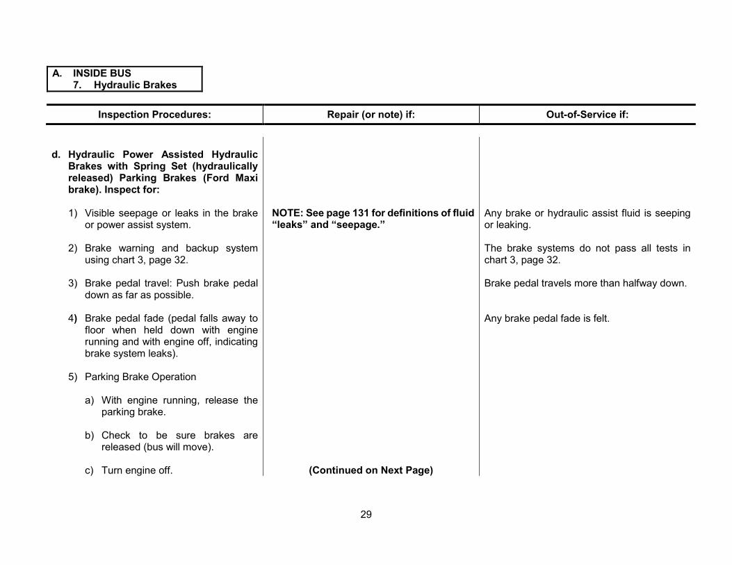
d. Hydraulic Power Assisted Hydraulic Brakes with Spring Set (hydraulically released) Parking Brakes (Ford Maxi brake). Inspect for:
1) Visible seepage or leaks in the brake or power assist system.
2) Brake warning and backup system using chart 3, page 32.
3) Brake pedal travel: Push brake pedal down as far as possible.
4) Brake pedal fade (pedal falls away to floor when held down with engine running and with engine off, indicating brake system leaks).
5) Parking Brake Operation
a) With engine running, release the parking brake.
b) Check to be sure brakes are released (bus will move).
c) Turn engine off.
NOTE: See page 131 for definitions of fluid Any brake or hydraulic assist fluid is seeping “leaks” and “seepage.” or leaking.
The brake systems do not pass all tests in chart 3, page 32.
Brake pedal travels more than halfway down.
Any brake pedal fade is felt.
(Continued on Next Page)
29

A. INSIDE BUS 7. Hydraulic Brakes
Inspection Procedures: Repair (or note) if: Out-of-Service if:
d) System must maintain pressure (keep parking brake released) for at least five minutes.
e) With parking brake applied and service brake released, apply engine torque by placing transmission selector in “D” and briefly accelerate the engine to approximately 1,200 RPM. Vehicle should not move forward.
6) Check all brake hardware and components inside the bus for secure mounting, routing and condition, including:
a) Brake pedal assembly and rubber cover pad (if originally equipped).
b) Emergency brake control assembly
Rubber cover pad is worn but not causing a slippery pedal condition.
Parking brake system will not hold pressure (i.e., release brakes) for at least five minutes.
Vehicle moves forward upon applying engine torque with park brake applied and service brake released.
Brake pedal assembly, push rod, clevis or emergency brake control assembly is insecurely mounted; poorly routed; has loose, missing or worn hardware; or is damaged.
Rubber cover pad is missing or badly worn.
Any part of pedal and assembly is damaged, loose, missing or modified.
Pedal has any type of extender block.
Emergency brake control is hard to operate or does not latch and release properly.
30

CHART 2
WARNING LIGHTS/BUZZER Normal Operation
MODE
Indicator Brake Lamp
Brake Electric Motor Lamp
Buzzer
1a. Engine Off/Ignition Off/no brake applied Off Off Off
1b. Engine Off/Ignition Off/brake applied Off On On
2. Engine Off/Ignition On or start with or without brake applied On On On
3. Engine On, with or without brake applied Off Off Off
Brake Failure Warning System Checks INTERNATIONAL/NAVISTAR
CONDITION NORMAL OPERATION PARK BRAKE LIGHT
Key switch in start position with park brake released - (bulb check).
Light on
Key switch on with park brake applied. Light on
BRAKE PRESSURE LIGHT Key switch off. Light off. Electric hydraulic pump
operates when service brakes are applied.
Key switch in on position. Engine not running (pump and bulb check).
Light on and electric hydraulic pump operation (some vehicles). See Navistar manual. Light on and electric hydraulic pump operates when service brakes are applied.
Key switch in on position and engine operating with service brakes applied.
Light off
Key switch in start position. Light on momentarily and electric hydraulic pump operates.
Key switch in on position and engine operating with service brakes applied. Light off
FORD
MODE
Normal Operation
Brake Warning
Light
Brake Electric Hydraulic
Boost Warning Light
Tone Alarm
1. Engine off/ignition off A. No brake applied B. Brake applied
Off On
Off Off
Off Off
2. Engine off/ignition on, with or without brake applied (bulb check).
On On On
3. Engine off/ignition on, start with or without brake applied.
On Off On
4. Engine on, with or without brake applied. Off Off Off
GMC
31

CHART 3 FORD HYDRAULIC, MAXI BRAKE SYSTEM NORMAL BRAKE SYSTEM CONDITIONS
CONTROLS RESULTS
ENGINE IGNITION SERVICE BRAKE
PARKING BRAKE SERVICE BRAKE
*ELECTRIC PUMP PARKING BRAKE
OFF ON LIGHT LIGHT BUZZER LIGHT **BUZZER
OFF ON OFF ON START OFF or ON RELEASED APPLIED
OFF ON OFF ON OFF ON OFF ON OFF ON
PARTIALLY FULLY PARTIALLY FULLY
X X X X or X X X X X X
X X X X or X X X X X X
X X X or X X X X X X X
X X X or X X X X X X X
X X X or X X X X X X X
X X X or X X X X X X X
X X X or X X X X X X X
X X X or X X X X X X
* Whenever the ignition switch is in the start position, the Hydro-Max electric pump will cycle momentarily.
** Parking brake buzzer will sound momentarily during application of the parking brake in cold ambient conditions.
32

A. INSIDE BUS 8. Windshield Wipers and Washers
Inspection Procedures:
a. Operation
Inspect both wipers for:
1) Swept area field of view and effectiveness of wiping.
2) Proper operation on high and low speeds, intermittent function (if equipped) condition, and mounting of switches and knobs.
3) Condition and mounting of wiper motors and linkage.
4) Proper washer operation.
b. Park
Inspect for parked position of wipers when turned off (electric) or when manually parked (air).
c. Blades
Inspect blades for condition, mounting and tension.
Repair (or note) if:
Either wiper does not operate on low speed or intermittent function (if equipped) does not work properly or wiper goes past perimeter of glass.
Washer is slightly misadjusted.
Poor cleaning of windshield.
Out-of-Service if:
Any wiper does not operate properly at high speed and switches or knobs are missing or loose.
Either wiper motor or linkage is visibly damaged, loose or excessively worn.
Electric wipers do not automatically return to parked position out of the driver’s line of sight when turned off, or air wipers cannot be manually parked out of the driver’s line of sight.
Either blade is missing, damaged, deteriorated, loose, does not hold proper tension against windshield or does not effectively clear driver’s field of vision.
33

A. INSIDE BUS 9. Heaters, Defrosters, Auxiliary Dash or
Header Fan(s)
Inspection Procedures: Repair (or note) if: Out-of-Service if:
NOTE: See page 131 for definitions of fluid “leaks” and “seepage.”
a. Heaters
Inspect heater system for performance, Coolant control valve is hard to operate. operation and condition.
Any blower does not work on all speeds, is noisy or vibrates, or switches are loose or improperly labeled.
(Continued on Next Page)
System is not producing heat.
Any blower is extremely noisy, indicating imminent failure or system wiring and connections are loose, damaged or chafed, creating an electrical short or high resistance.
Heater hoses are cracked, swollen or badly chafed, or there is any coolant leakage inside the bus.
Hose and/or component shielding is missing or does not completely cover hoses/components in a manner that protects passengers from contact with hot surfaces and prevents spraying of coolant in the event of a hose/component failure.
Any portion of heating system within passenger area creates sharp edges, projections or other hazards to passengers.
34
A. INSIDE BUS 9. Heaters, Defrosters, Auxiliary Dash or
Header Fan(s)
Inspection Procedures: Repair (or note) if: Out-of-Service if:
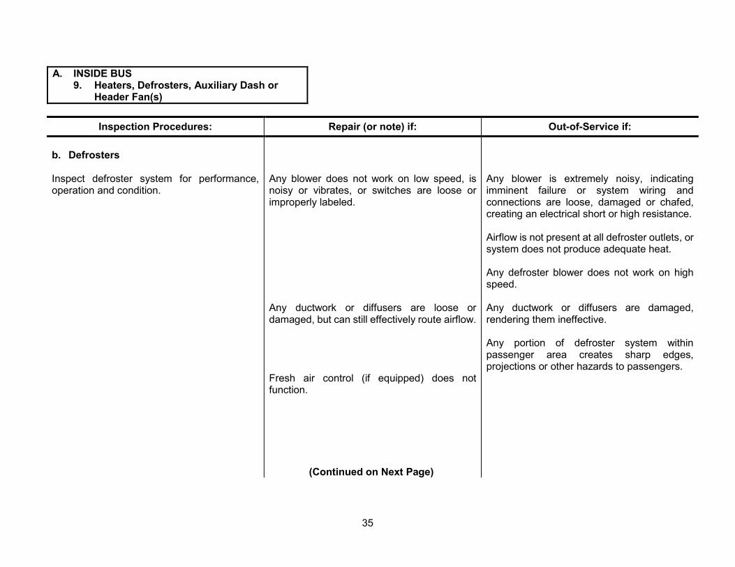
b. Defrosters
Inspect defroster system operation and condition.
for performance, Any blower does not work on low speed, is noisy or vibrates, or switches are loose or improperly labeled.
Any ductwork or diffusers are loose or damaged, but can still effectively route airflow.
Fresh air function.
control (if equipped) does not
(Continued on Next Page)
Any blower is extremely noisy, indicating imminent failure or system wiring and connections are loose, damaged or chafed, creating an electrical short or high resistance.
Airflow is not present at all defroster outlets, or system does not produce adequate heat.
Any defroster blower does not work on high speed.
Any ductwork or diffusers are damaged, rendering them ineffective.
Any portion of defroster system within passenger area creates sharp edges, projections or other hazards to passengers.
35

A. INSIDE BUS 9. Heaters, Defrosters, Auxiliary Dash or
Header Fan(s)
Inspection Procedures: Repair (or note) if: Out-of-Service if:
c. Auxiliary Dash Fan
Inspect fan for performance, operation and condition.
Note: Dash fan may be squirrel cage type and header-mounted on some buses.
Fan does not work on low speed, is noisy or vibrates, or switches are loose or improperly labeled.
Fan is extremely noisy, indicating imminent failure or wiring, and connections are loose, damaged or chafed, creating an electrical short or high resistance.
Fan is not present, is loose, or it will not stay adjusted.
Protective cage is missing, loose or damaged.
Fan does not operate.
36

A. INSIDE BUS 10. Dome and Step Well Lights
Inspection Procedures: Repair (or note) if: Out-of-Service if:
Dome and Step Well Lights
Check passenger and driver dome lights for condition and operation. A driver dome light has been required since September 1995.
Any lens is cracked or dirty.
Any single passenger dome light is working.
not
Any lens is broken or missing, exposing light bulb or fixture.
Two or more passenger dome lights are not working.
Dome light switch is loosely mounted. Any driver’s compartment dome light is not working.
Check step well lights for condition and operation.
Step well light is on when door is closed.
Lens is cracked or dirty.
Step well light does not activate when clearance lights are on and the service door is open.
37

A. INSIDE BUS 11. Service Door
Inspection Procedures: Repair (or note) if: Out-of-Service if:
a. Operation
Check service door assembly for operation, adjustment, condition, mounting and fit.
(Continued on Next Page)
Air or manual door binds, or will not open a minimum of 24 inches or is unsecure in the closed position.
Manual door control requires more than 25 pounds of effort to open or close.
Manual door control will not lock open over center, or closed latching mechanism is inoperative.
Air door emergency release does not function properly.
Air door opens or closes at an excessive rate and force or too slowly.
Air door system leaks air.
Glass is broken, cracked or has been replaced with material other than laminated or tempered safety glass.
Door glass is fogged more than one inch in from edges, or visibility through the glass is poor.
Door is equipped with a locking system that is not OEM factory approved.
38

A. INSIDE BUS 11. Service Door
Inspection Procedures: Repair (or note) if: Out-of-Service if:
Door assembly is damaged, not securely mounted or has excessively worn hinges, pins, bearings/bushings or other components.
Door does not seal properly or damaged, ripped or deteriorated.
seals are Door seals are not present.
b. Overhead Pad
Check bus for a padded safety cushion directly Pad is loose or cover has minor damage or Pad is missing or cover has excessive above the inside of the service door. Pad is wear. damage or wear, exposing foam. required to be a minimum of three inches wide.
39
A. INSIDE BUS
12. Horns
Inspection Procedures: Repair (or note) if: Out-of-Service if:
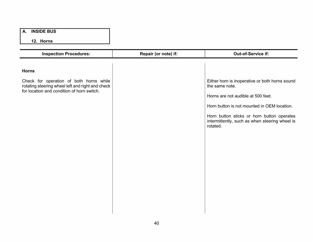
Horns
Check for operation of both horns while rotating steering wheel left and right and check for location and condition of horn switch.
Either horn is inoperative or both horns sound the same note.
Horns are not audible at 500 feet.
Horn button is not mounted in OEM location.
Horn button sticks or horn button operates intermittently, such as when steering wheel is rotated.
40

A. INSIDE BUS 13. Mirror Adjustment and Condition
Inspection Procedures: Repair (or note) if: Out-of-Service if:
a. Rear-View Mirror System (Traffic Mirrors)
Check exterior (flat and convex) rear-view Electrically controlled mirror (if applicable) is mirrors for specifications, condition and not operating properly and can still be adjusted adjustment. manually.
(Continued on Next Page)
Any required rear-view mirror is not present.
Rear-view mirrors cannot be adjusted.
Any mirror is cracked, broken or has reflective surface deterioration; view is diminished; or any damage is visible.
Any mirror does not meet applicable specifications.
Any rear-view mirror is out of adjustment. (If in doubt, consult with operations supervisors and/or driver trainers).
41

A. INSIDE BUS 13. Mirror Adjustment and Condition
Inspection Procedures: Repair (or note) if: Out-of-Service if:
b. Cross/Side-View Mirror System (Cross-walk Mirrors)
Check cross-walk/side-view mirrors for specifications, condition and adjustment.
Note: “No blind-spot” mirror system (meeting new performance specifications), has been a requirement since November 1990. (i.e., single cross-walk/side-view mirror at each front corner).
(Continued on Next Page)
Any required cross-walk/side-view mirror is not present.
Any mirror is cracked, broken or has reflective surface deterioration; view is diminished; or any damage is visible.
Any mirror does not meet applicable specifications.
Any cross-walk/side-view mirror is out of adjustment, i.e., mirrors do not provide driver with an indirect view of the area at ground level from the front bumper forward, the entire width of the bus and around the left and right front corners so that the driver can see by direct vision, and/or does not provide driver with indirect vision of the area at ground level, to include the tires and service entrance on all types of buses so that view overlaps with the rear-view mirror system. (If in doubt, consult with operations supervisors and/or driver trainers).
42
A. INSIDE BUS 13. Mirror Adjustment and Condition
Inspection Procedures: Repair (or note) if: Out-of-Service if:
c. Interior Mirror
Check interior mirror for specifications, condition and adjustment.
Interior mirror is not present.
Mirror is cracked, broken or has reflective surface deterioration; or view is diminished by distortion, stickers or other items.
Interior rearview mirror is not at least six inches x 30 inches (except Type A1, which shall be a minimum of 50 square inches).
Mirror does not have rounded corners and protected edges.
Mirror or mounting/adjusting system is loose or cannot be adjusted by the driver.
43

A. INSIDE BUS 14. Driver’s Seat and Seat Belt
Inspection Procedures: Repair (or note) if: Out-of-Service if:
Driver’s Seat and Belt
Inspect driver’s seat and belt for specifications, condition, mounting and operation. Air suspension seat required on all air brake equipped buses since September 1995.
Buses manufactured since 1989 require high back seat with cloth insert and a three-point shoulder harness/lap belt assembly.
Seat adjustments are stiff but still operational.
Seat upholstery or foam is deteriorated or damaged.
Driver’s seat will not adjust forward and back and up and down and remain in position; back will not tilt and lock into position; or adjustment hardware is loose, missing or damaged.
Seat assembly is unstable, cracked or damaged or loose at floor; mounting hardware is missing or not OEM or equivalent.
Buses manufactured since 2009 require bright orange or lime green seat belt webbing.
Type A1 buses require manufacturer’s standard driver seat and belt assembly.
Driver’s seat belt webbing is incorrect color (not orange or lime green for new buses manufactured since 2009).
(Continued on Next Page)
Seat bottom or back is loose, or frame is exposed due to deterioration of upholstery or foam.
Seat suspension system is leaking air.
Wrong type of seat, not meeting specifications, has been installed.
Driver’s seat belt is missing; is wrong type (i.e., not manufacturer’s standard for year, make and model of bus); belt guides or retractors are insecure, damaged or not operating properly; belt is loose or routed improperly or does not extend or retract freely; or buckle-and-tongue assembly does not latch or release properly.
Seat belt is frayed or damaged.
44

A. INSIDE BUS 15. Passenger Seats
Inspection Procedures: Repair (or note) if: Out-of-Service if:
a. Frames
Inspect passenger seat frames for condition, hardware and modifications.
Check for presence of non-OEM seat frames.
Any seat frame tubing or welds are broken or cracked; any frame has been repaired, modified or reinforced using non-OEM approved hardware or methods or projections; or sharp edges exist.
Any non-OEM seat frames have been installed.
b. Mounting
Inspect condition of passenger seat mounting. Mounting at floor or seat rail is loose; components are cracked, broken or damaged; or any fasteners are missing, damaged or not OEM or equivalent.
(Continued on Next Page)
45

A. INSIDE BUS 15. Passenger Seats
Inspection Procedures: Repair (or note) if: Out-of-Service if:
c. Backs/Crash Barriers/Padding
Inspect seat back, crash barriers and padding for specifications and condition.
Requirements:
1) Up to early 2007 models: Standard height padded seat backs, approximately 24 inches high measured from the seat bottom cushion.
2) Early 2007 to present year models: High-back padded seat backs, approximately 28 inches high measured from the seat bottom cushion.
Any bus manufactured since April 1977 does not have a properly spaced and padded crash barrier forward of any passenger seat without another seat directly ahead (exception: Pre-1990 Type A Bus).
Original thickness or density of any seat back or crash barrier foam has been reduced due to wear, damage, deterioration or other factors so that there is no padding between any portion of seat back frame and covering.
Any seat back or crash barrier foam is the wrong type (i.e., not manufacturer standard for year, make and model of bus).
(Continued on Next Page)
46
A. INSIDE BUS 15. Passenger Seats
Inspection Procedures: Repair (or note) if: Out-of-Service if:
d. Bottoms
1) Inspect seat bottoms for securement and condition.
2) Inspect automatic retracting seat bottom at side emergency door for proper operation, if equipped. Must have clear access to emergency door, with a minimum aisle width of 12 inches between seats.
Any seat bottom is not attached to its seat frame; or tilt-up bottoms will not latch or stay latched in the closed position.
Original thickness or density of any seat bottom cushion is reduced due to wear, damage, deterioration or other factors so that there is no padding between any portion of seat bottom frame and covering.
Any seat bottom has a protruding edge or its plywood is broken.
Any automatically retracting seat bottom will not fold down, automatically retract and stay in position when not occupied, or there is less than a 12-inch aisle width between the seat and the side emergency door.
(Continued on Next Page)
47
A. INSIDE BUS 15. Passenger Seats
Inspection Procedures:
e. Cuts and other upholstery damage
Inspect seat upholstery for condition and specifications.
Note: The use of fire-blocking seat material is required since 1989.
Note: Punctures where no material is missing and no foam is exposed shall not be cause for removing bus from service.
f. Modesty Panels
Inspect modesty panels for presence, condition and mounting.
g. Optional Integrated Child Seating
Check the condition and operation of the seating system.
Repair (or note) if:
(Continued on Next Page)
Out-of-Service if:
Any portion of seat bottom or back upholstery is missing, cut, torn, ripped or improperly repaired, exposing foam.
Any upholstery is non-fire-blocking type for buses built since 1989.
Any modesty panel is missing, excessively loose or damaged, causing sharp edges or pinch points.
If the integrated system does not function properly according to the manufacturer’s operational procedures or any of the same out-of-service conditions exist as applicable to regular passenger seats.
48

A. INSIDE BUS 15. Passenger Seats
Inspection Procedures: Repair (or note) if: Out-of-Service if:
h. Passenger Securement Devices (if equipped).
All buses equipped with two or three-point passenger securement systems shall be equipped with FMVSS No. 210 compliant seat frames and FMVSS No. 209 compliant belt assemblies in all passenger-seating positions.
Check type, condition and operation of passenger securement devices.
Type A buses built since April 1, 1977, must have a functional seat belt at each passenger position. All buses ordered after January 1, 2001, must be equipped with seat belts at all seating positions.
i. Webbing Cutter
Check for presence, type, condition and mounting of the required webbing cutter. It must be mounted in a location accessible to the driver from a seated position and be easily detachable.
Each two-part belt assembly is not separately color-coded.
Belts are knotted or misrouted or retractor covers are damaged or loose.
Note: Lift-equipped buses or buses using other assistive/restraining devices containing webbing must have a second webbing cutter properly mounted in a location determined by the school district.
Belts will not latch, stay latched or unlatch properly or are the wrong type, missing, broken, mismatched, improperly installed or excessively frayed.
Any required webbing cutter is missing, broken, unusable, improperly mounted or difficult to remove.
Wrong type of webbing cutter.
49

A. INSIDE BUS 16. Emergency Doors, Windows, Hatches and Passenger Check System
Inspection Procedures: Repair (or note) if: Out-of-Service if:
a. Operation
Inspect for operation and condition of rear emergency exit door and side emergency exit door (if equipped), door hold-open feature (buses built after November 1993), emergency exit windows and emergency exit roof hatches.
Any emergency exit handle, guard or latch mounting hardware is slightly loose.
Powered roof hatch ventilator (if equipped) does not work properly.
Roof hatch seal is damaged or dislodged.
(Continued on Next Page)
Any emergency exit does not operate smoothly and easily to a fully open position and back to closed, from the inside and outside when unlatching, opening, closing and latching (windows from inside only).
Door (or rear window on rear engine (RE) buses) hold-open feature does not secure the exit in the fully open position.
Any emergency exit handle, guard, latch or mounting hardware is missing, or latching mechanism does not operate smoothly and secure the exit in the closed position.
Roof hatch is insecure in the ventilation position.
Any emergency exit is equipped with any type of a hasp, lock or any other locking device, except for an OEM interlock system.
Bus will start with any emergency door (or rear window on RE buses) locked.
Any emergency exit door does not seal off the entire opening when latched closed.
50

A. INSIDE BUS 16. Emergency Doors, Windows, Hatches and Passenger Check System
Inspection Procedures: Repair (or note) if: Out-of-Service if:
b. Buzzers
Check emergency exit door(s) and window warning buzzers.
c. Labeling and Pad
1) Inspect for identification and operating instruction labels and for emergency door, windows, roof hatches and hold-open device.
2) Inspect emergency door header pad.
Hold-open device operating instructions label is missing or illegible.
Door pad is ripped or loose.
Buzzer warning system for emergency door (or rear window on RE buses) or any exit window does not function, gives false alarms or is not audible in the driver’s compartment.
Buzzer operation is intermittent.
All emergency exits are not clearly labeled “Emergency Door” or “Emergency Exit” on the inside and outside of the bus.
Any emergency door (or rear window on RE buses), window or roof hatch does not have clearly labeled instructions on the inside and outside.
Door pad is missing or has a protruding edge.
(Continued on Next Page)
51

A. INSIDE BUS 16. Emergency Doors, Windows, Hatches and Passenger Check System
Inspection Procedures: Repair (or note) if: Out-of-Service if:
d. Post-Trip Passenger Check System (if applicable)
Check for proper operation of post-trip passenger check system (required on buses manufactured since 2005).
Post-trip passenger check system is Buses built since 2005 are not equipped with inoperative or does not operate according to a post-trip passenger check system. specifications.
52

A. INSIDE BUS 17. Windshield, Side and Rear
Windows
Inspection Procedures: Repair (or note) if: Out-of-Service if:
a. Glass Cracks
Inspect windshield and all windows for cracks and other damage.
Note: Windshield must be laminated safety glass. All other windows can be made from laminated or tempered safety glass.
(Continued on Next Page)
Windshield has any cracks, chips or damage that obstructs the driver’s view.
Any windshield or other laminated safety glass window is cracked greater than two inches in length or any laminated glass crack or splinter creates a sharp surface that could cause injury when touched.
Any tempered safety glass is cracked.
Any window rearward of the windshield is not laminated, tempered or equivalent safety glass.
Any glass is missing.
53
A. INSIDE BUS 17. Windshield, Side and Rear
Windows
Inspection Procedures: Repair (or note) if: Out-of-Service if:
b. Fogging, Tinting and Visibility
Check windshield and windows for fogging, reduced visibility or improper level of tinting.
(Continued on Next Page)
Any glass is fogged more than two inches in from any outer edge.
Any windshield or window fogging or clouding results in reduced visibility of a mirror.
Any tinting on the windshield or windows to either side of the driver in the driver’s compartment (including service door) is not 70 percent light transmitting or clearer.
Any tinted windows behind the driver’s compartment are not 28 percent light transmitting or clearer.
Visibility is reduced for any reason (except for the allowed fogging from the repair or note column).
54

A. INSIDE BUS 17. Windshield, Side and Rear
Windows
Inspection Procedures: Repair (or note) if: Out-of-Service if:
c. Latches and Window Operation
Check latches and windows for condition and Any window latch is difficult to operate, or any operation. window does not move up and down freely.
d. Visor
Check sun visors for condition and operation.
Any window will not move fully up and down or will not stay closed.
Any window has loose, damaged or protruding hardware in the passenger compartment.
Sun visor is cracked or damaged, cannot be adjusted or will not stay in position.
Visibility is reduced for any reason (clouded, dirty or has foreign objects or decals affixed).
Sun visor is missing.
55

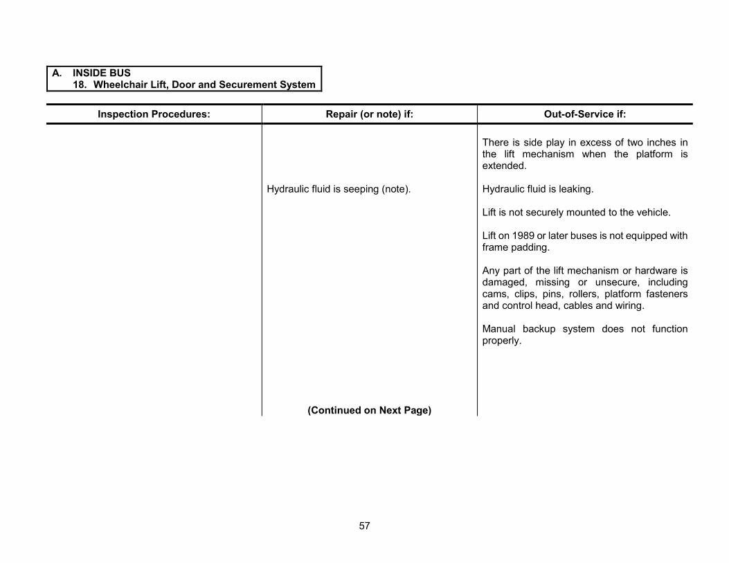
A. INSIDE BUS 18. Wheelchair Lift, Door and Securement System
Inspection Procedures: Repair (or note) if: Out-of-Service if:
Wheelchair Lift, Door and Securement System
1) Operate lift through complete cycle and inspect for proper operation, condition, safety features, manual backup system, fluid leakage/seepage, mounting, roll stop operation, warning light, buzzer operation and overall mechanical condition.
Note: See page 131 for definitions of fluid “leaks” and “seepage.”
Dome light at inside lift area is inoperative.
Lift door or latch does not operate smoothly.
White light at exterior lift area (if originally equipped) is inoperative.
Lift door warning buzzer or light does not operate.
Lift door latches, weather stripping or securement system is damaged or loose.
Door switch (to prevent lift operation when the lift door is closed) or other safety override features do not function.
Lift does not properly deploy, lower, raise or retract; jerks; binds; or jacks the vehicle when fully lowered.
Inboard and outboard roll stops, or handrails do not deploy and retract reliably to the proper positions.
Lift will not stay in the fully retracted position (falls against door).
(Continued on Next Page)
Lift safety chain or belt (if originally equipped) is damaged or missing, or lift safety interlock system is not operating according to manufacturer’s specifications.
56
A. INSIDE BUS 18. Wheelchair Lift, Door and Securement System
Inspection Procedures: Repair (or note) if: Out-of-Service if:
Hydraulic fluid is seeping (note).
(Continued on Next Page)
There is side play in excess of two inches in the lift mechanism when the platform is extended.
Hydraulic fluid is leaking.
Lift is not securely mounted to the vehicle.
Lift on 1989 or later buses is not equipped with frame padding.
Any part of the lift mechanism or hardware is damaged, missing or unsecure, including cams, clips, pins, rollers, platform fasteners and control head, cables and wiring.
Manual backup system does not function properly.
57

A. INSIDE BUS 18. Wheelchair Lift, Door and Securement System
Inspection Procedures: Repair (or note) if: Out-of-Service if:
2) Inspect wheelchair and occupant securement (tie-down) system for proper operation, condition, mounting, type and location.
Note: Starting in 1989, each 50-inch section of tie-down track may consist of two pieces of track, with neither piece less than 16 inches long, and must extend the full length of the wheelchair position, with no gaps.
3) Check for presence, proper type, proper mounting and condition of a second durable webbing cutter.
Note: Buses equipped with lifts and other assistive/restraining devices containing webbing must have a second webbing cutter properly mounted in a location determined by the school district.
Track contains dirt/debris, but occupant securement straps and wheel chair tie-down straps can still be easily attached to or detached from the track.
Optional below-chair rail lighting for wheelchair securement area (if equipped) is inoperative.
Track contains excessive dirt or debris. Wheelchair tie-down track or fasteners are loose, broken, corroded or improper type (i.e., lag bolts, sheet metal screws, etc.).
Any 50-inch wheelchair position has more than two pieces of track, or any piece of track is shorter than 16 inches. Pre-1989, any wheelchair position does not have continuous one-piece, 50-inch tracks.
Wheelchair or occupant securement straps are broken or frayed, cannot be easily attached to or detached from track, or will not operate.
Securement system for buses built between October 1983 and November 1989 is not a side-facing, track-and-belt system meeting Florida specifications.
Securement system (for buses built after November 1989) is not a forward-facing wheelchair and occupant securement system meeting Florida specifications.
Any required webbing cutter is missing, broken, unusable, improperly mounted or difficult to remove.
Wrong type of webbing cutter.
58

A. INSIDE BUS 19. Two-Way Radio Operation
Inspection Procedures: Repair (or note) if: Out-of-Service if:
Two-Way Radio Operation (if equipped)
Inspect radio and antenna for condition, Radio will not transmit or receive. mounting, location and routing of wiring, and perform function check.
Mounting is loose.
Driver has to move out of the normal driving position to operate radio.
Wiring or connectors are routed or installed incorrectly, or there is the possibility of an electrical short circuit due to unsecured or damaged wiring.
Any part of radio, external speaker, microphone or wiring interferes with driver’s controls or blocks any of the driver’s view through any portion of windshield or other window.
59
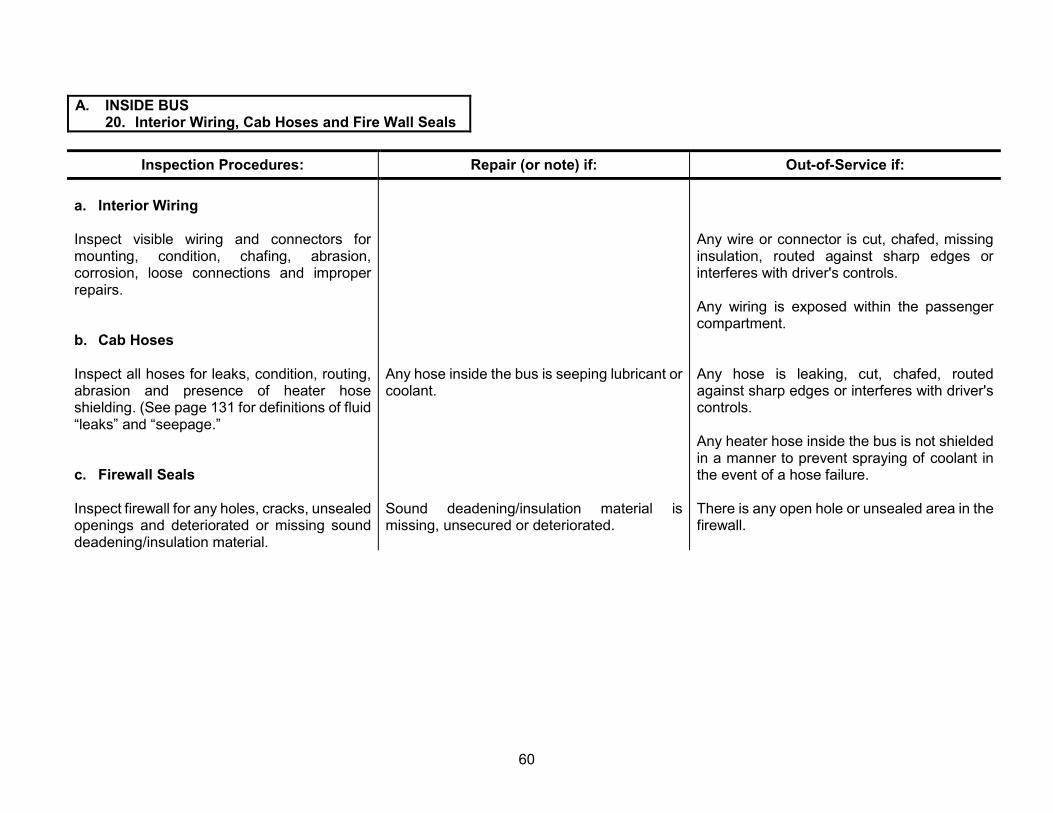
A. INSIDE BUS 20. Interior Wiring, Cab Hoses and Fire Wall Seals
Inspection Procedures: Repair (or note) if: Out-of-Service if:
a. Interior Wiring
Inspect visible wiring and connectors for mounting, condition, chafing, abrasion, corrosion, loose connections and improper repairs.
b. Cab Hoses
Inspect all hoses for leaks, condition, routing, abrasion and presence of heater hose shielding. (See page 131 for definitions of fluid “leaks” and “seepage.”
c. Firewall Seals
Inspect firewall for any holes, cracks, unsealed openings and deteriorated or missing sound deadening/insulation material.
Any hose inside the bus is seeping lubricant or coolant.
Sound deadening/insulation material is missing, unsecured or deteriorated.
Any wire or connector is cut, chafed, missing insulation, routed against sharp edges or interferes with driver's controls.
Any wiring is exposed within the passenger compartment.
Any hose is leaking, cut, chafed, routed against sharp edges or interferes with driver's controls.
Any heater hose inside the bus is not shielded in a manner to prevent spraying of coolant in the event of a hose failure.
There is any open hole or unsealed area in the firewall.
60

A. INSIDE BUS 21. General Condition of Bus Interior
Inspection Procedures: Repair (or note) if: Out-of-Service if:
a. Floor
Inspect floor covering, plywood sub-floor (if installed), aisle and cove molding strips, and ribbed rubber in aisle for condition, adhesion, loose or missing fasteners, and/or holes and cracks.
b. Stepwell
Check specifications and condition of step well and tread.
Floor covering material is loose, deteriorated or cracked.
There are any unsealed holes or cracks through the floor to underside of bus.
Plywood is soft. Aisle is not equipped with 12-inch wide ribbed rubber.
Any aisle or front-area-molding strip is not securely fastened to floor, or any aisle or cove molding presents a sharp edge or protrusion.
Any damage, wear or condition of the floor covering material and moldings presents a tripping hazard.
Step tread is not sealed at inside edge where it meets next step.
Step well tread and jointing edge at aisle are not flush and securely adhered.
Step well tread ribs/nubs on top surface at leading edge are worn smooth more than four inches in width.
Step well support structure is not secure, broken, or step well is rusted through.
(Continued on Next Page)
61
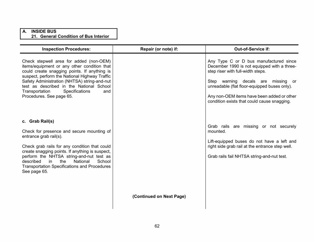
A. INSIDE BUS 21. General Condition of Bus Interior
Inspection Procedures:
Check stepwell area for added (non-OEM) items/equipment or any other condition that could create snagging points. If anything is suspect, perform the National Highway Traffic Safety Administration (NHTSA) string-and-nut test as described in the National School Transportation Specifications and Procedures. See page 65.
c. Grab Rail(s)
Check for presence and secure mounting of entrance grab rail(s).
Check grab rails for any condition that could create snagging points. If anything is suspect, perform the NHTSA string-and-nut test as described in the National School Transportation Specifications and Procedures See page 65.
Repair (or note) if:
(Continued on Next Page)
Out-of-Service if:
Any Type C or D bus manufactured since December 1990 is not equipped with a three-step riser with full-width steps.
Step warning decals are missing or unreadable (flat floor-equipped buses only).
Any non-OEM items have been added or other condition exists that could cause snagging.
Grab rails are missing or not securely mounted.
Lift-equipped buses do not have a left and right side grab rail at the entrance step well.
Grab rails fail NHTSA string-and-nut test.
62

A. INSIDE BUS 21. General Condition of Bus Interior
Inspection Procedures: Repair (or note) if: Out-of-Service if:
d. Paneling and Trim
Check front, sides, rear, ceiling and driver’s area paneling and trim pieces for secure fastening, projections, sharp edges, pinch points and condition.
There are loose or missing fasteners on any maintenance access panel.
There is graffiti, unauthorized stickers, missing paint or mildew on interior panels.
Sharp edges, pinch points, excessive rust, loose fasteners or projections from paneling exist that could cause injury to passengers or driver.
There are any non-flush mounted speakers (except trim rings) or any other unauthorized items affixed to the interior paneling of the bus in the passenger area.
There is excessive graffiti or mildew inside the bus.
e. Broom Mounting
Check securement and location of broom. Broom is not securely mounted in the driver’s compartment.
(Continued on Next Page)
63

A. INSIDE BUS 21. General Condition of Bus Interior
Inspection Procedures: Repair (or note) if: Out-of-Service if:
f. Loose Objects and Cleanliness
Check to see that all objects within the bus are secured.
Check cleanliness of bus.
Check for the presence of aerosol containers Trash not emptied from trash can or floor not and non-aerosol liquid containers. swept.
g. Dog House/Engine Cover
Inspect dog house/engine cover seals, Soundproofing is not present or is loose or soundproofing, weather stripping, prop-rod deteriorated. and latch operation.
Loose objects such as trashcans, clothing, cleaning supplies are present that are not located in a secured compartment or container.
There is excessive dirt or trash on the floor, causing it to be slippery.
Any aerosol cans or other containers with flammable or volatile contents are present.
Any unlabeled liquid container is present.
Seals or weather stripping are leaking and allowing air/fumes into driver’s compartment.
Prop-rod does not safely support the dog house/engine cover.
Latches are hard to operate or do not secure the dog house/engine cover properly.
64

CHART 4 NUT-AND-STRING TEST
The Handrail Inspection Tool and Procedure
The inspection tool is inexpensive, and the procedure for detecting potentially fatal handrail designs is quite simple. The inspection tool is a standard one half inch hex nut, measuring three-quarters of an inch across the flats. This nut is tied to a one-eighth inch thick cotton cord measuring 36 inches in length with overhand knots. The drawstring should have a minimum length of 30 inches when tied to the nut and attached so that a pull of at least 10 pounds does not separate the nut from, or break the drawstring. Steps to conduct a handrail inspection are:
Stand on the ground outside of the bus; Drop the inspection tool between the handrail and step well wall, simulating the typical way students exit the bus; Draw the inspection tool through the handrail in a smooth, continuous slow motion; and Repeat this procedure a minimum of three times.
Note: It is important to drop the inspection tool over the handrail in such a way as to simulate a child exiting the bus. This is a drop-and-drag test. Do not create a snagging situation by placing the nut in an area that would not be exposed to a drawstring or other articles.
Inspection Results Take the bus out-of-service and repair it if the inspection tool catches or snags anywhere on the handrail. If the nut separates from the drawstring or the drawstring breaks, reassemble the tool and retest. If the inspection tool pulls freely without catching or snagging, the bus should not be rejected.
65

(This Page Intentionally Left Blank)
66
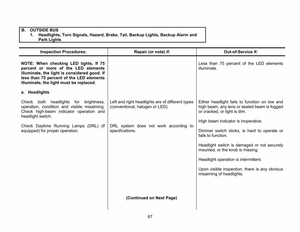
B. OUTSIDE BUS 1. Headlights, Turn Signals, Hazard, Brake, Tail, Backup Lights, Backup Alarm and
Park Lights
Inspection Procedures: Repair (or note) if: Out-of-Service if:
NOTE: When checking LED lights, If 75 percent or more of the LED elements illuminate, the light is considered good. If less than 75 percent of the LED elements illuminate, the light must be replaced.
a. Headlights
Check both headlights for brightness, operation, condition and visible misaiming. Check high-beam indicator operation and headlight switch.
Check Daytime Running Lamps (DRL) (if equipped) for proper operation.
Left and right headlights are of different types (conventional, halogen or LED).
DRL system does not work according to specifications.
Less than 75 percent of the LED elements illuminate.
Either headlight fails to function on low and high beam, any lens or sealed beam is fogged or cracked, or light is dim.
High beam indicator is inoperative.
Dimmer switch sticks, is hard to operate or fails to function.
Headlight switch is damaged or not securely mounted, or the knob is missing.
Headlight operation is intermittent.
Upon visible inspection, there is any obvious misaiming of headlights.
(Continued on Next Page)
67

B. OUTSIDE BUS 1. Headlights, Turn Signals, Hazard, Brake, Tail, Backup Lights, Backup Alarm
and Park Lights
Inspection Procedures: Repair (or note) if: Out-of-Service if:
b. Turn Signals
Check turn signals for operation, condition Any turn signal lens is cracked. and specifications (see charts 6 and 7 on pages 83 and 84).
(Continued on Next Page)
Any turn signal fails to function, does not flash or is dim.
Turn signals do not flash 60 to 120 times per minute.
Any bus manufactured since December 1990, is not equipped with side-mounted turn signals, and buses over 30 feet in length do not have two signals on each side.
Any turn signal is not amber in color.
Any turn signal lens is damaged, darkened, faded or dirty, affecting visibility or color of the light, or white light is visible.
Turn signal switch does not function properly, will not maintain selected position, or does not cancel and return to neutral position.
Turn signal dash indicators fail to function or do not properly indicate position of turn signal switch and operation of signal.
68

B. OUTSIDE BUS 1. Headlights, Turn Signals, Hazard, Brake, Tail, Backup Lights, Backup Alarm
and Park Lights
Inspection Procedures: Repair (or note) if: Out-of-Service if:
c. Hazard Lights
Check four-way hazard lights for operation and condition.
Any lens is cracked or dirty. Any four-way hazard light fails to function.
Hazard lights do not flash 60 to 120 times per minute.
Switch does not function or will not maintain the “on” position.
d. Brake Lights
Check brake lights for operation, condition and specifications (see chart 7, page 84).
One brake light fails to function on buses with four brake light systems.
More than one brake light fails to function on buses with four brake light systems.
Either brake light fails to function on buses with two brake light systems.
Brake lights stay on after brake pedal is released.
(Continued on Next Page)
69

B. OUTSIDE BUS 1. Headlights, Turn Signals, Hazard, Brake, Tail, Backup Lights, Backup Alarm
and Park Lights
Inspection Procedures: Repair (or note) if: Out-of-Service if:
Any brake light lens is cracked.
e. Tail Lights
Check tail lights for operation, condition and One tail light fails to function on buses with specifications (see chart 7, page 84). four tail light systems.
Any tail light lens is cracked.
(Continued on Next Page)
Any 19 capacity or larger bus built since November 1980 is not equipped with two seven-inch and two four-inch brake lights.
Any brake light is not red in color.
Any brake light lens is damaged, darkened, faded or dirty; affecting visibility or color of the light, or white light is visible.
More than one tail light fails to function on buses with four brake light system.
Either tail light fails to function on buses with two brake light system.
Tail light operation is intermittent.
Any 19 capacity or larger bus built since November 1980 is not equipped with two seven-inch and two four-inch taillights.
Any tail light is not red in color.
Any tail light lens is damaged, darkened, faded or dirty, affecting visibility or color of the light, or white light is visible.
70
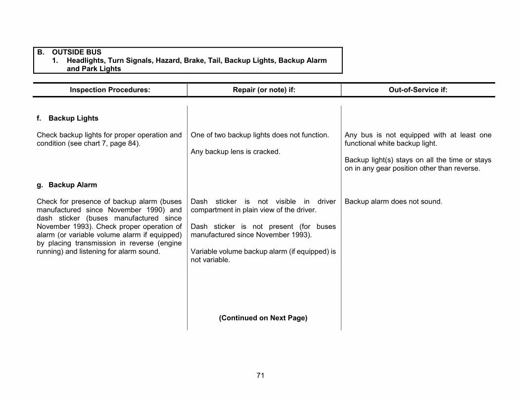
B. OUTSIDE BUS 1. Headlights, Turn Signals, Hazard, Brake, Tail, Backup Lights, Backup Alarm
and Park Lights
Inspection Procedures: Repair (or note) if: Out-of-Service if:
f. Backup Lights
Check backup lights for proper operation and condition (see chart 7, page 84).
g. Backup Alarm
Check for presence of backup alarm (buses manufactured since November 1990) and dash sticker (buses manufactured since November 1993). Check proper operation of alarm (or variable volume alarm if equipped) by placing transmission in reverse (engine running) and listening for alarm sound.
One of two backup lights does not function. Any bus is not equipped with at least one functional white backup light.
Any backup lens is cracked. Backup light(s) stays on all the time or stays on in any gear position other than reverse.
Dash sticker is not visible in driver Backup alarm does not sound. compartment in plain view of the driver.
Dash sticker is not present (for buses manufactured since November 1993).
Variable volume backup alarm (if equipped) is not variable.
(Continued on Next Page)
71

B. OUTSIDE BUS 1. Headlights, Turn Signals, Hazard, Brake, Tail, Backup Lights, Backup Alarm
and Park Lights
Inspection Procedures: Repair (or note) if: Out-of-Service if:
h. Parking Lights
Check parking lights for proper operation and One front or rear parking light fails to function condition (see charts 6 and 7, pages 83 and on buses with four front and four rear parking 84). light systems.
Any parking light lens is cracked or damaged.
More than one front or rear parking light fails to function on buses with four front and four rear parking light systems.
One front or rear parking light fails to function on buses with a two parking light system.
Any parking light lens is damaged, darkened, faded or dirty, affecting visibility or color of the light, or white light is visible.
72

B. OUTSIDE BUS 2. Clearance, Side Marker, ID Lights, Reflectors and Strobe Light
Inspection Procedures: Repair (or note) if: Out-of-Service if:
a. Clearance, Side Marker and ID lights
Check lights for operation, condition and location. Also check license plate light (see charts 6 and 7 on pages 83 and 84).
Note: When there are two lights factory-mounted at the top corners, the front is a clearance and the side is a side marker. When there is one light factory-mounted at the top corners, it is a clearance/side marker combination, meeting both requirements.
Any intermediate (center) side marker light fails to function.
Any clearance or ID light lens is cracked.
One or two ID lights (but not all ID lights) on the front or rear of the bus fail to function.
License plate light is inoperative.
(Continued on Next Page)
Any front or rear top corner-mounted clearance, side marker or clearance/side marker combination light fails to function.
Any bus over 30 feet in length is not equipped with intermediate amber side marker lights on both sides.
Any intermediate or front clearance, side marker, clearance/side marker combination light or ID light lens is not amber.
Any rear clearance, side marker, clearance/side marker combination light or ID lens is not red.
Any clearance, side marker, clearance/side marker combination light or ID light lens is damaged, darkened, faded or dirty, affecting visibility or color of the light, or white light is visible.
All ID lights on either the front or the rear of the bus are inoperative.
73

B. OUTSIDE BUS 2. Clearance, Side Marker, ID Lights, Reflectors and Strobe Light
Inspection Procedures: Repair (or note) if: Out-of-Service if:
b. Reflectors
Check reflectors for condition and location (see charts 6 and 7 on pages 83 and 84).
Note: Reflectors are required as follows: 1) Buses over 30 feet in length: two red on
rear, one red on each side at rear, one intermediate amber on each side, one amber at front and one amber front of cowl on each side.
2) Buses under 30 feet in length: same, except intermediate amber reflectors are not required.
c. Strobe Light
Check roof-mounted white flashing strobe light for operation, location and condition.
Any reflector is damaged or cracked. Any required reflectors are missing.
Any required reflector is faded, significantly affecting its original color.
Any bus manufactured since December 1990 is not equipped with a roof-mounted white flashing strobe light mounted in the center of the roof approximately 48 inches from the rear of the bus.
The strobe light on any bus built prior to December 1990 is not mounted in the center of the rear part of the roof.
Strobe light does not function.
(Continued on Next Page)
74

B. OUTSIDE BUS 3. Pupil Warning Lights
Inspection Procedures: Repair (or note) if: Out-of-Service if:
Pupil Warning Lights
Check pupil warning lights for operation and Either of the two pupil warning lights or interior condition (see charts 6 and 7 on pages 83 and pilot lights fail to function. 84).
Note: See chart 5, page 76, for function checks.
Note: Pupil warning light hoods in the front and rear of the bus are not required since September 1993.
Any pupil warning light fails to function or is dim.
Front and rear amber and red lights do not alternately flash (side to side).
Any outer pupil warning light is not red, inner pupil warning light is not amber, or any pupil warning light is not OEM or equivalent.
Any pupil warning light lens is damaged and white light is visible.
Any pupil warning light lens is obstructed, misaimed, dirty, darkened or faded, affecting the color of the light or reducing the visibility to less than 500 feet in bright sunlight.
Pupil warning lights fail to function according to all conditions in chart 5, page 76.
75

CHART 5 EIGHT-LIGHT WARNING SYSTEM
NOTE: System may not be designed in such a way that the operator is required to actuate controls in a particular sequence to achieve the desired combination of conditions.
EXAMPLE: If the driver places the three-position switch in the amber position with the master switch on, he should not have to move the three-position switch to red or open the service door to deactivate the amber warning lights. The driver must be able to deactivate the amber warning lights by going directly from the amber to the off position.
WITH MASTER SWITCH, CONTROL SWITCH and SERVICE DOOR CONDITION OF STOP ARM(S), STOP ARM LIGHTS, AMBER IN THE FOLLOWING POSITIONS: WARNING LIGHTS AND RED WARNING LIGHTS MUST BE:
MASTER CONTROL AMBER SWITCH SWITCH SERVICE STOP ARMS, WARNING RED WARNING *AUDIBLE
POSITION POSITION DOOR STOP ARM and and ALARM (ON or OFF) (three-positions: OFF, POSITION LIGHTS PILOT LIGHTS PILOT LIGHTS
AMBER or RED)
1) ON OFF CLOSED RETRACTED, OFF OFF OFF OFF
2) ON OFF OPEN RETRACTED, OFF** OFF ON ON
3) ON AMBER CLOSED RETRACTED, OFF ON OFF OFF
4) ON AMBER OPEN RETRACTED, OFF** OFF ON ON
5) ON RED CLOSED EXTENDED, ON OFF ON OFF
6) ON RED OPEN EXTENDED, ON OFF ON OFF
7) OFF ANY POSITION ANY POSITION RETRACTED, OFF OFF OFF OFF
* Note: Effective September 1, 1992. **Note: The stop arm lights may flash in the retracted position on buses built prior to November 1983.
76
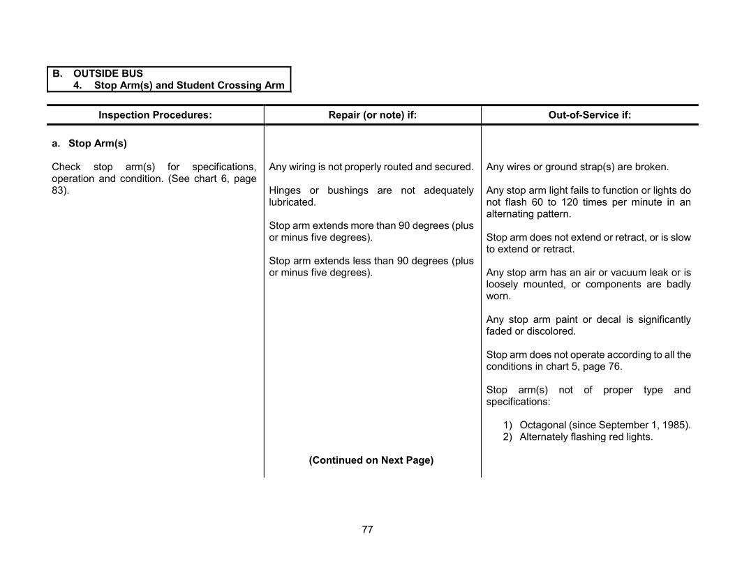
B. OUTSIDE BUS 4. Stop Arm(s) and Student Crossing Arm
Inspection Procedures: Repair (or note) if: Out-of-Service if:
a. Stop Arm(s)
Check stop arm(s) for specifications, Any wiring is not properly routed and secured. operation and condition. (See chart 6, page 83). Hinges or bushings are not adequately
lubricated.
Stop arm extends more than 90 degrees (plus or minus five degrees).
Stop arm extends less than 90 degrees (plus or minus five degrees).
(Continued on Next Page)
Any wires or ground strap(s) are broken.
Any stop arm light fails to function or lights do not flash 60 to 120 times per minute in an alternating pattern.
Stop arm does not extend or retract, or is slow to extend or retract.
Any stop arm has an air or vacuum leak or is loosely mounted, or components are badly worn.
Any stop arm paint or decal is significantly faded or discolored.
Stop arm does not operate according to all the conditions in chart 5, page 76.
Stop arm(s) not of proper type and specifications:
1) Octagonal (since September 1, 1985). 2) Alternately flashing red lights.
77

B. OUTSIDE BUS 4. Stop Arm(s) and Student Crossing Arm
Inspection Procedures: Repair (or note) if: Out-of-Service if:
Check that rear stop-arm decal is not present on forward side of arm on buses built after September 1, 1993.
b. Student Crossing Arm (if equipped)
Check front bumper-mounted student crossing arm for specifications, operation and condition.
Note: For crossing arm and stop arm requirements, see Federal Motor Vehicle Safety Standard (FMVSS) 131.
Crossing arm extends more than 90 degrees (plus or minus five degrees).
Crossing arm extends less than 90 degrees (plus or minus five degrees).
Hinges or bushings are not adequately lubricated.
3) High intensity reflectivity (since December 1990).
4) Dual stop arms required on all modified Type B and Type C 47-passenger capacity and up and all Type D since December 1990.
A stop arm decal has been installed on the forward side of the rear stop arm for buses built after September 1, 1993.
Not equipped with student crossing arm, since December 1992.
Crossing arm does not extend or retract, or is slow to extend or retract.
Any crossing arm has an air or vacuum leak, is loosely mounted or has badly worn components.
78

B. OUTSIDE BUS 5. General Condition of Bus Exterior
Inspection Procedures: Repair (or note) if: Out-of-Service if:
a. Mirrors
Check all exterior mirrors, mounts and brackets for tightness and condition.
b. Bumpers
Check bumpers for mounting, condition, color Bumper is not black. and body seal on rear bumper.
Bumper is equipped with any unauthorized stickers or decals.
(Continued on Next Page)
Mirror mounts or bracket(s) are bent, broken, not secure, or have loose or missing fasteners.
Any exterior mirror is broken, cracked or loose in the frame, or reflective surface is faded or deteriorated.
Bumper is significantly bent or has protruding metal.
Bumper, mounts or braces are bent, broken, not secure, or have loose or missing fasteners.
Diagonal reflective striping (if equipped) is missing, significantly damaged or not reflective.
Front bumper on buses built since October 1982 permanently deforms or is not of sufficient strength to allow the front of the bus to be lifted without permanent deformation.
Rear bumper to body seal is damaged or missing.
79

B. OUTSIDE BUS 5. General Condition of Bus Exterior
Inspection Procedures: Repair (or note) if: Out-of-Service if:
c. Body Damage
Check body exterior for damage, scratches, Body has small dents, scratches, etc. dents, etc.
Body has small rust spots or water leaks.
d. Paint
Check paint on body, trim and wheels for Paint is faded, discolored or damaged. required coloration and condition.
e. Reflective Markings (if equipped)
Check reflective markings for coloration, Reflective markings other than those around reflectivity and condition. Reflective markings any emergency exit as required by FMVSS required since September 1995. No. 217 are faded, discolored, damaged or
peeling.
Check for presence of reflective markings around any emergency exit door, window or roof hatch as required by FMVSS No. 217 (buses purchased after November 1993).
(Continued on Next Page)
Any body part is damaged or dislocated, creating a protrusion or sharp edge.
Body panels, rivets or other components are damaged or corroded so that joint strength or body structural integrity is compromised.
Paint is not National School Bus Yellow (except white roof). Trim, rub rails, warning light, hoods or background are not black. Stud-piloted disk wheels and spoke hub-mounted wheels are not black, or hub-piloted wheels are not National School Bus Yellow.
Any required reflective markings are missing, significantly faded or discolored around any emergency exit door, window or roof hatch.
80
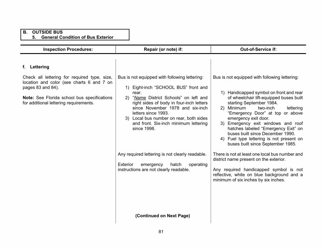
B. OUTSIDE BUS 5. General Condition of Bus Exterior
Inspection Procedures: Repair (or note) if: Out-of-Service if:
f. Lettering
Check all lettering for required type, size, location and color (see charts 6 and 7 on pages 83 and 84).
Note: See Florida school bus specifications for additional lettering requirements.
Bus is not equipped with following lettering:
1) Eight-inch “SCHOOL BUS” front and rear.
2) “Name District Schools” on left and right sides of body in four-inch letters since November 1978 and six-inch letters since 1993.
3) Local bus number on rear, both sides and front. Six-inch minimum lettering since 1998.
Any required lettering is not clearly readable.
Exterior emergency hatch operating instructions are not clearly readable.
Bus is not equipped with following lettering:
1) Handicapped symbol on front and rear of wheelchair lift-equipped buses built starting September 1984.
2) Minimum two-inch lettering “Emergency Door” at top or above emergency exit door.
3) Emergency exit windows and roof hatches labeled “Emergency Exit” on buses built since December 1990.
4) Fuel type lettering is not present on buses built since September 1985.
There is not at least one local bus number and district name present on the exterior.
Any required handicapped symbol is not reflective, white on blue background and a minimum of six inches by six inches.
(Continued on Next Page)
81

B. OUTSIDE BUS 5. General Condition of Bus Exterior
Inspection Procedures: Repair (or note) if: Out-of-Service if:
g. Emergency Door Operation
Check emergency door for operation and condition from exterior of bus.
h. Engine Hood
Check engine hood for operation, condition Hood is misaligned. and safety latch.
Hood hinges are stiff or damaged, but remain operational.
i. Cleanliness
Check exterior of bus for cleanliness. Exterior of bus is dirty.
Emergency door is hard to open fully from outside of bus.
Emergency door latch mechanism requires more than 40 pounds to release.
Emergency door handle is mounted to allow “hitching” onto the bus.
Hood cannot be opened as designed.
Safety latch is damaged or stiff, or does not secure the hood.
Hood prop rod(s) or hold-open feature does not function properly.
Bus is dirty to the point that visibility through any window or mirror, or brightness of any light, is significantly reduced.
82

CHART 6 MINIMUM LETTERING AND LIGHTING REQUIREMENTS
A. Clearance and Side Marker Lights (one intermediate on buses 30 feet or longer).
BB. Stop Arm(s)
C. Front Turn Signals and Parking Lamps
F. Pupil Warning Lights--Dual (side by side, amber and red)
G. Reflectors, one at rear body side panel, one near front of body and one intermediate (only on buses 30 feet or longer) on both sides
I. Emergency Exit Lettering
J. Double-Faced Flashing Red Lights
K. “School Bus” Lettering (front and rear) (see specifications)
L. (Name of District) District Schools (both sides)
M. Local Bus Number (both sides and front and back)
N. Universal Handicapped Symbol (lift buses)
O. Identification Lamps
S. Battery Box
U. Pupil Crossing Arm
Y. Rear-View Mirror System (see specifications)
Z. Cross/Side View Mirror System (see specifications)
83
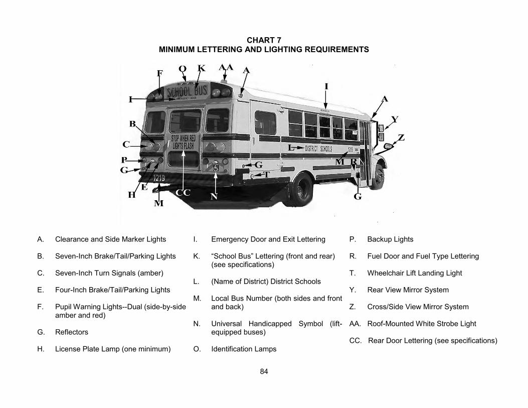
CHART 7 MINIMUM LETTERING AND LIGHTING REQUIREMENTS
A. Clearance and Side Marker Lights I.
B. Seven-Inch Brake/Tail/Parking Lights K.
C. Seven-Inch Turn Signals (amber) L.
E. Four-Inch Brake/Tail/Parking Lights M.
F. Pupil Warning Lights--Dual (side-by-side amber and red)
N. G. Reflectors
H. License Plate Lamp (one minimum) O.
Emergency Door and Exit Lettering P. Backup Lights
“School Bus” Lettering (front and rear) R. Fuel Door and Fuel Type Lettering (see specifications)
T. Wheelchair Lift Landing Light (Name of District) District Schools
Y. Rear View Mirror System Local Bus Number (both sides and front and back) Z. Cross/Side View Mirror System
Universal Handicapped Symbol (lift- AA. Roof-Mounted White Strobe Light equipped buses)
CC. Rear Door Lettering (see specifications) Identification Lamps
84
C. ENGINE COMPARTMENT 1. Steering
Inspection Procedures: Repair (or note) if: Out-of-Service if:
a. Steering Wheel, Play and Assist
Check condition of the steering wheel.
Check for play in the steering system at the steering wheel using the following procedures:
1) Visual check: From inside bus with engine running, rotate steering wheel lightly from side to side until motion can be observed at tires. Measure the free play (lash) at steering wheel outer diameter. This procedure must be performed with the vehicle on the ground.
2) To check power assist operation, run engine at fast idle, turn steering wheel a full right and left turn, and feel for binding, jamming or belt slippage.
Steering wheel OEM covering has minor wear, cracks or looseness not exposing metal reinforcement.
Any portion of the OEM covering is loose, deteriorated, cracked or missing, exposing metal steering wheel reinforcement or interfering with usage.
Steering wheel is loose on column.
Steering wheel or covering is non-OEM design.
Free play (lash) exceeds amounts specified in chart 8, page 86.
Power assist is inadequate, or there is binding, jamming or belt slippage.
(Continued on Page 87)
85

CHART 8
STEERING WHEEL PLAY (LASH) MEASUREMENTS
Figure 1 Figure 2
Steering Wheel Size Wheel (rim) Size: 15 inches – 1-3/4” (4.4 cm) 16 inches or less - 1/4” (6.5 mm) 16 inches - 2” (5.1 cm) 17 to 18 inches - 3/8” (9.5 mm) 18 inches – 2-1/4” (5.7 cm) Over 18 inches - 1/2” (13 mm) 20 inches – 2-1/2” (6.4 cm) 22 inches – 2-3/4” (7.0 cm)
86

C. ENGINE COMPARTMENT 1. Steering
Inspection Procedures: Repair (or note) if: Out-of-Service if:
b. Column
Check steering column inside bus for up-and-down play (parallel to shaft), side-to-side play (perpendicular to shaft) and proper mounting.
c. Steering Gear Box and other external components
Check condition of the steering system using the following procedures with the vehicle on the ground (not suspended):
Any column shaft yoke, coupler or joint dust boot is torn.
(Continued on Next Page)
Column side-to-side play exceeds one-fourth inch or up-and-down play exceeds one inch.
Column assembly mounting (including floor mounting plate) or fasteners are loose.
Tilt/telescopic assembly (if equipped) will not stay locked in position.
Steering column shaft U-joint inside the bus (if equipped) is loose, damaged or noisy after lubrication.
Firewall or floor rubber boot is torn, ripped or missing.
Steering column shaft u-joints, couplers, slide yokes, pinch bolts, etc., are loose, worn, damaged, have excessive play, or have loose or missing fasteners.
Any column shaft yoke, coupler or joint dust boot is missing.
Steering gear box is loose on frame or any fasteners are loose or missing.
87

C. ENGINE COMPARTMENT 1. Steering
Inspection Procedures:
1) With engine running, have assistant move steering wheel back and forth repeatedly to load steering components.
2) Observe the following external steering and related suspension and frame components for looseness while assistant works the steering (also see specific procedures under each component):
a) Column shaft and hardware b) Column U-joints, couplers, slide
yokes (as equipped) c) Coupling at gear box d) Gear box e) Pitman arm f) Drag link g) Steering knuckle or arms h) Tie rod ends i) Idler arm (as equipped) j) Vehicle frame cross-members and
frame braces, including associated rivets and fasteners for looseness and condition.
Repair (or note) if: Out-of-Service if:
There is any binding in steering gear box.
Frame braces or cross-members are cracked, loose or missing fasteners.
Any axle or suspension/steering component is loose or worn beyond specifications prescribed elsewhere in this manual.
(Continued on Next Page)
88

C. ENGINE COMPARTMENT 1. Steering
Inspection Procedures: Repair (or note) if: Out-of-Service if:
3) Have an assistant carefully rotate the steering wheel all the way to the left, then all the way to the right, to check the steering stops, and to check the power steering pressure relief valve.
d. Pitman Arm
Check the Pitman arm for looseness or misalignment at sector shaft splines and looseness at all joints. Check looseness of pinch bolt and fasteners and condition of Pitman arm.
Pitman arm grease fitting (if equipped) is loose or missing.
(Continued on Page 91)
Tire contacts any part of the bus frame, suspension, steering or other components.
Any play is observed between Pitman arm and sector shaft.
Pinch bolt at sector shaft is loose or missing.
Pitman arm to steering sector shaft marks are misaligned.
Pitman arm ball joint (if equipped) has more than one-sixteenth inch axial play (i.e., in-and-out play between the ball stud and socket; see figure 6, page 93).
Pitman arm ball joint nut or cotter pin is loose or missing.
Pitman arm is cracked or damaged.
89

TIGHTENING STEERING COLUMN JOINT BOLTS
WARNING: FAILURE TO MAINTAIN THE STEERING SYSTEM IN PROPER CONDITION CAN CAUSE REDUCED STEERING FUNCTION, RESULTING IN PERSONAL INJURY AND PROPERTY DAMAGE.
It is recommended that steering column joint bolts be checked for tightness every 50,000 miles or annually, whichever occurs first. DO NOT OVERTIGHTEN
90
C. ENGINE COMPARTMENT 1. Steering
Inspection Procedures: Repair (or note) if: Out-of-Service if:
e. Drag Link
Check the drag link ends, shaft and fasteners for looseness and condition.
f. Steering Arm
Check upper steering arm (Ackerman arm) and left and right side lower steering arms for securement and condition.
Check condition and securement of steering stops and lock nuts.
Any grease fitting is loose, missing or will not take grease.
Drag link ball stud is loose in Pitman arm or upper steering arm.
Drag link needs lubrication. Any nut or cotter pin is loose or missing.
Drag link dust boots are cut, damaged or missing.
Drag link shaft is damaged or bent.
Drag link ends axial or horizontal play exceeds one-sixteenth inch (See figure 6, page 93).
Horizontal socket type (adjustable) drag link end has more than one-sixteenth inch axial or lateral play.
Any steering arm is bent, cracked or damaged.
Any steering arm attachment point is loose, or any fasteners or cotter pins are missing.
Either steering stop or lock is loose, damaged or missing.
(Continued on Next Page)
91

C. ENGINE COMPARTMENT 1. Steering
Inspection Procedures: Repair (or note) if: Out-of-Service if:
g. Tie Rod and Ends
Check tie rod, tie rod ends, dust boots, clamps and fasteners for looseness, damage and condition.
h. Idler Arm
Check idler arm assembly (as equipped) for looseness, damage and condition.
Tie rod end dust boots are cut, damaged or missing.
Tie rod end needs lubrication.
Any tie rod end grease fitting is loose, missing or will not take grease.
Tie rod to end clamps or fasteners are stripped, missing, loose or improperly positioned for proper clearance.
Any tie rod or end is bent, cracked or damaged.
Tie rod ends axial or horizontal play exceeds one-sixteenth inch. (See figure 6, page 93).
Tie rod end ball stud is loose in steering arm or idler arm, has missing or loose fasteners, or has missing cotter pins.
Idler arm needs lubrication.
Idler arm grease fitting is loose, missing or will not take grease.
Idler arm is cracked or damaged, or cotter pin is missing.
Idler arm up-and-down play is greater than one-fourth inch total (one-eighth inch either direction). (See figure 7, page 93.)
92
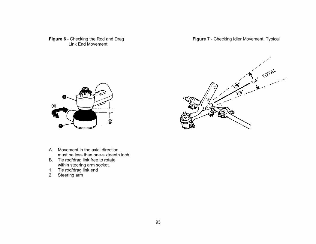
Figure 6 - Checking the Rod and Drag Figure 7 - Checking Idler Movement, Typical Link End Movement
A. Movement in the axial direction must be less than one-sixteenth inch.
B. Tie rod/drag link free to rotate within steering arm socket.
1. Tie rod/drag link end 2. Steering arm
93

C. ENGINE COMPARTMENT 2. Batteries
Inspection Procedures: Repair (or note) if: Out-of-Service if:
a. Battery Box, Door and Tray
Check battery box, door and tray for Battery slide tray is corroded, dirty or hard to operation, condition and securement. slide in and out.
b. Hold-down
Check for tightness, condition and type of battery hold-down.
c. Battery Terminals
Check terminals for cleanliness, tightness and condition.
d. Battery Cables
Check cable assemblies for routing, securement, condition and size.
Battery slide tray or box is loose, corroded or damaged, reducing securement of the batteries, or door does not open or will not stay latched.
Battery slide tray does not slide in and out or tray lock, or stop is missing or nonfunctional.
Hold-down assembly is not OEM design, missing, loose, corroded or damaged, reducing securement of the batteries.
Any terminal is loose, damaged, corroded or has missing hardware or insulation.
Cable or insulation is cracked, damaged or corroded.
Cable is misrouted, unsecured or missing protective grommets, loom or other means of protection from chafing against any metal, sharp edge or hot surface.
Cable is smaller than original equipment size.
(Continued on Next Page)
94

C. ENGINE COMPARTMENT 2. Batteries
Inspection Procedures: Repair (or note) if: Out-of-Service if:
e. Cleanliness
Check cleanliness of battery or batteries.
f. Electrolyte Level
Check electrolyte in battery or batteries for proper level (if applicable).
Battery top or sides are corroded, greasy, dirty or wet with electrolyte.
Electrolyte is low (not exposing plates).
(Continued on Page 97)
Cable appears to be too small in diameter or of excessive length (see chart 9, page 96).
Flat braided engine ground cable is frayed or corroded, or ends are not secure.
Batteries and compartment are excessively dirty or corroded.
Electrolyte is low (exposing plates).
95

CHART 9
CHARGING SYSTEMS CABLE SIZE CHART
SYSTEM VOLTAGE
RATED OUTPUT
IN AMPERES
RECOMMENDED MINIMUM CHARGING CABLE GAUGE SIZE
4 FT. or Less 4 -7 FT. 7 -10 FT. 10 -13 FT. 13 -16 FT. 16 -19 FT. 19 -22 FT. 22 -28 FT.
12 VOLT
0 - 20 14 12 12 10 10 8 8 8
20 - 35 12 10 8 8 6 6 6 4
35 - 50 10 8 8 6 6 4 4 4
50 - 65 8 8 6 4 4 4 4 2
65 - 85 6 6 4 4 2 2 2 0
85 - 105 6 6 4 2 2 2 2 0
105 - 125 4 4 4 2 2 0 0 0
125 - 150 2 2 2 2 0 0 0 00
Maximum difference between battery voltage and alternator voltage is 0.5 volt for 12-volt systems at full-rated output.
Maximum voltage drop in the sensing (#2-terminal) lead must not exceed 0.2 volt for 12-volt three-wire systems.
Cable gauge size calculation above takes into account terminal-connection resistance.
Note: When an insulated (no frame ground) charging system is installed, the length of the return circuit must be included to obtain total circuit length and determine the proper wire size.
96

C. ENGINE COMPARTMENT 2. Batteries
Inspection Procedures: Repair (or note) if: Out-of-Service if:
g. Load Test (Optional)
Perform battery load test on battery or batteries to check condition. Check battery or batteries for proper type and load rating.
Battery cable length or battery mounting restricts access to battery or batteries for servicing.
Battery or batteries are of insufficient cold cranking amp (CCA) rating.
Battery fails load test (see chart 10, page 97).
CHART 10 BATTERY TEST
REMOVE SURFACE-CHARGE: Discharge at 300 amps for 15 seconds.
Check for blue haze or smoke.
TEST Measure electrolyte temperature. Discharge at
one-half the CCA rating of the battery for 15 seconds.
Battery voltage must not drop below the listed values during the 15-second test.
Degrees in F Min. Voltage 70 or over------------------------- 9.6
60------------------------------- 9.5 50------------------------------- 9.4 40------------------------------- 9.3 30------------------------------- 9.1 20------------------------------- 8.9 10------------------------------- 8.7 0-------------------------------- 8.5
97

C. ENGINE COMPARTMENT 3. Fluid Levels and Condition
Inspection Procedures: Repair (or note) if: Out-of-Service if:
a. Brake Fluid
Check brake fluid and brake power-assist hydraulic fluid (if equipped) for level and condition.
b. Power Steering Fluid
Check power steering fluid level and condition.
c. Oil
Check engine oil level and condition. Engine oil level is below the “full” mark.
(Continued on Next Page)
Level of brake fluid in either side of master cylinder reservoir is lower than one-fourth inch from top or below “add” mark.
Brake fluid or power-assist fluid shows evidence of excessive water, oil or dirt contamination.
Brake power-assist hydraulic fluid is below cold “add” mark.
Power steering fluid shows evidence of excessive water, oil or dirt contamination.
Power steering fluid is below cold “add” mark.
No oil is observed on dipstick.
Dipstick is missing.
Engine oil level is below the “add” mark or above “full” mark.
There is evidence of fuel or water contamination in the oil.
98

C. ENGINE COMPARTMENT 3. Fluid Levels and Condition
Inspection Procedures: Repair (or note) if: Out-of-Service if:
d. Transmission Fluid
Check transmission fluid level and condition.
e. Windshield Washer Fluid
Check windshield washer fluid level.
Transmission fluid level is below the “full” mark.
Transmission fluid shows need of servicing (discoloration or smell).
Reservoir level is low or cap is missing.
Dipstick is missing, broken or the incorrect type.
Transmission fluid is below the “add” mark or above the “full” mark.
Transmission fluid shows evidence of excessive dirt, metal or coolant contamination.
Reservoir is empty.
(Continued on Next Page) 99

C. ENGINE COMPARTMENT 3. Fluid Levels and Condition
Inspection Procedures: Repair (or note) if: Out-of-Service if:
f. Coolant
Check engine coolant level, condition and freeze protection.
Note: Follow manufacturer’s recommendations for checking coolant condition, PH and additive package.
Note: Use caution when opening a hot cooling system.
Coolant level is below the “full” mark.
Coolant shows evidence of excessive oil, dirt contamination, or rust and corrosion.
Coolant freeze protection is minus 20 degrees Fahrenheit or lower (see chart 11, page 101).
Coolant pH level is too high or too low, or coolant additive package has depleted to an unacceptable level.
Coolant level is below the “add” mark or cannot be seen in the reservoir or radiator with cap removed.
100

CHART 11
Freezing-Points of Antifreeze Solutions
SOLUTION PROTECTION Percentage
of Antifreeze
Percentage of
Water Celsius Fahrenheit 0% 0% 0 32 10% 90% -3 27 12% 88% -4 25 14% 86% -5 23 16% 84% -6 21 18% 82% -7 19 20% 80% -8 18 24% 76% -10 14 28% 72% -13 9 30% 70% -15 5 32% 68% -16 3 36% 64% -20 -4 40% 60% -24 -11 44% 56% -28 -18 48% 52% -33 -27 50% 50% -37 -35 52% 48% -39 -38 56% 44% -45 -49 60% 40% -51 -60
Boiling Points of Antifreeze Solutions at Various Pressures
Pressure in Pounds per Square Inch (PSI) 0 PSI 8 PSI 12 PSI 16 PSI 20 PSI
Percentage of
Antifreeze Solution
0% 212 233 242 252 260 33% 220 240 253 260 268 44% 224 245 257 265 272 50% 226 248 259 267 275 60% 231 253 264 273 280
Boiling Points in Degrees Fahrenheit (°F)
Note: Technicians should test engine coolant properties during every inspection using a coolant-test-strip kit. Consult the Original Equipment Manufacturer (OEM) for recommended test kits and procedures.
101
C. ENGINE COMPARTMENT 4. Belts and All Hoses
Inspection Procedures: Repair (or note) if: Out-of-Service if:
a. Belt(s)
1) Tightness
Visually and physically check all drive belts for proper tension. If available, use a tension gauge (see figure 9, page 103). If a gauge is not available, use a ruler to measure the deflection of the belt(s) up and down at the widest point between the drive and driven pulley(s) (see figure 10, page 103).
2) Condition
Inspect belt(s) for presence, glazing, oil contamination, dry rotting, cuts and separation of plies. Check belts for twisting or distortion.
3) Routing and Alignment
Inspect belt(s) for correct routing, alignment and contact with objects other than pulleys.
Any belt exceeds tension reading recommended by manufacturer.
Using ruler method, any belt has less than half an inch deflection (too tight) when firm pressure is applied (See figure 10, page 103).
Any belt is glazed.
Any belt is slightly misaligned.
(Continued on Next Page)
Any belt tensioner (automatic or manual) does not apply proper tension to belt.
Tension on any belt is too loose (based on specifications of type tension gauge used).
Tension of any belt (using ruler method) is too loose when firm pressure is applied (greater than three-fourth inch deflection).
Any belt is missing, oil saturated, dry-rotted or cut, or plies of belt(s) are separated.
Any belt is twisted or distorted.
Belt misalignment is excessive and could result in failure.
Any belt is making contact with objects other than pulley(s).
Any belt is routed incorrectly.
102

CHECKING BELT TENSION AFTER TIGHTENING
Figure 9 - Checking Belt Tension Figure 10 - Measuring Belt Tension (Gauge Method) (Ruler Method)
103

C. ENGINE COMPARTMENT 4. Belts and All Hoses
Inspection Procedures: Repair (or note) if: Out-of-Service if:
b. Hose(s)
1) Clamps and Connections
Visually and physically check that hose connections or clamp(s) are tight.
Note: References to hoses include all types of hoses located in the engine compartment and related components, including power steering, coolant, air compressor intake, vacuum, brake hydraulic assist, engine oil and transmission hoses.
2) Condition
Inspect all hoses for cuts, abrasions and wear, oil saturation, dry rotting and ballooning.
3) Routing
Inspect routing and securement of all hoses.
Any hose connection or clamp is loose or overtightened.
Any hose connection (other than brake) is seeping.
Any hose is misrouted or unsecured so that heat, abrasion or other damage is possible.
Any hose connection or clamp is stripped, damaged or overtightened, causing hose damage beyond the outer cover.
Any brake hose is seeping or leaking.
Any hose is cut, abraded, worn, oil-saturated, dry-rotted or ballooned to the point that failure is likely.
Any hose is misrouted or unsecured so that heat, abrasion or other damage is likely.
104

C. ENGINE COMPARTMENT 5. Accessory Mounting and Condition
Inspection Procedures: Repair (or note) if: Out-of-Service if:
a. Air Cleaner
Check air intake system, housing, lid, piping, Any portion of air intake system has minor gaskets, seals and clamps for leaks, dents or damage that is not causing air leaks. securement and condition. Record air filter restriction gauge measurement.
Note: If air leaks are suspect, inspect for Air filter restriction gauge is not working dirt/dust tracking through air cleaner properly. assembly and intake piping.
b. Power Steering Pump
Check securement and condition of power steering pump.
c. Air Compressor and Filter
Check securement and condition of air Air compressor external air filter (if equipped) compressor and filter assembly. is dirty.
(Continued on Next Page)
There are intake system leaks; loose, missing or damaged components; or other conditions that could allow dust or dirt damage to internal engine parts.
Air filter restriction exceeds manufacturer’s specifications.
Any portion of the power steering pump, mounting brackets or fasteners is cracked, damaged, loose or missing.
Any portion of the air compressor, mounting brackets, fasteners or compressor air-filter system is cracked, damaged, loose or missing.
105

C. ENGINE COMPARTMENT 5. Accessory Mounting and Condition
Inspection Procedures: Repair (or note) if: Out-of-Service if:
d. Water Pump
Check condition of water pump and pulley.
Note: See page 131 for definitions of fluid “leaks” and “seepage.”
e. Fan
Check fan blades, hub and fan clutch assembly for securement and condition.
f. Alternator
Check securement and condition of alternator assembly.
There is evidence of coolant seepage from water pump, seal, gasket surface or weep hole.
Alternator is noisy.
Water pump is noisy, bearing is damaged or coolant is leaking.
Water pump and/or fan fasteners are loose, damaged or missing to the point that failure or leaks could occur.
Fan has any cracked, bent or broken blades.
Any portion of fan mounting is loose.
Fan clutch is seized or loose.
Any of the alternator, mounting brackets or fasteners are cracked, loose or missing.
Alternator is not charging.
106

C. ENGINE COMPARTMENT 6. Wiring
Inspection Procedures: Repair (or note) if: Out-of-Service if:
Routing and Condition
Check routing, securement and condition of all wiring and any electrical cable in the engine compartment and related areas.
There is any slightly loose, damaged or corroded wiring connector or terminal end.
Any repair has been made using improper gauge wiring.
Any wiring is misrouted, unsecured or missing protective grommets, loom or other means of protection from chafing against any metal, sharp edge or hot surfaces.
There are any burnt wires, or any wires are missing insulation (other than ground straps).
107
C. ENGINE COMPARTMENT 7. Fuel System and Lines
Inspection Procedures: Repair (or note) if: Out-of-Service if:
Fuel System and Lines
Visually check the condition, operation and securement of all fuel system components, including fuel lines and routing in the engine compartment.
There is evidence of dirt, algae or water in a fuel water separator.
There is any unsecured, poorly routed or loose fuel line or hose that could cause fire due to abrasion or heat damage.
Any fuel system connection is stripped, loose, cracked or leaking.
Any fuel system component is damaged or not mounted securely.
108

C. ENGINE COMPARTMENT 8. Radiator
Inspection Procedures: Repair (or note) if: Out-of-Service if:
a. Radiator and Reservoir
Check radiator and reservoir assemblies for mounting, securement and condition.
b. Cap
Check condition of radiator cap and perform pressure test.
WARNING: ALWAYS USE PROPER PROCEDURES WHEN REMOVING A RADIATOR CAP.
Any portion of the radiator, reservoir or mounting system is cracked or damaged, or has loose or missing fasteners not causing leaks or failure.
Radiator cap is hard to open or close.
Radiator cap leaks down slowly at rated pressure.
Any portion of the radiator, reservoir or mounting system is cracked, damaged or has loose or missing fasteners, causing leaks or failure.
Radiator cap is missing.
Radiator cap is the incorrect type or pressure rating, or fails pressure test.
d. Fan Shroud
Check fan shroud for mounting and condition. Fan shroud is missing, loose or has excessive damage that may interfere with the cooling fan.
109

(This Page Intentionally Left Blank)
110

D. UNDERNEATH BUS 1. Front Suspension
Inspection Procedures: Repair (or note) if: Out-of-Service if:
a. Front Wheel Bearings
Inspect front wheel bearings and related components for condition and proper adjustment of bearings. With front wheels raised, grasp tire and attempt to rock wheel and move In-and-Out to check for play. Spin tire to check for noise and condition of bearings.
Note: To correctly identify the source of any play or to determine if the play is in wheel bearings, have an assistant press and hold the foot brake pedal (ensuring the front brakes are engaged) while rechecking play. If movement disappears with brakes applied, then the play was in the wheel bearings.
b. I-Beam
Inspect I-beam axle assembly.
Oil or grease is seeping from hub bearing caps.
Oil or grease is leaking from hub bearing caps.
Note: See page 131 for definitions of fluid “leaks” and “seepage.”
Wheel bearing endplay exceeds manufacturer’s specifications of .010-inch maximum, measured at the hub.
Any noise, binding or roughness is discovered in bearings.
I-beam has been heated, cut or modified, or is cracked or damaged.
(Continued on Next Page)
111

D. UNDERNEATH BUS 1. Front Suspension
Inspection Procedures: Repair (or note) if: Out-of-Service if:
c. Kingpins
Inspect kingpin assemblies for condition and play as follows:
Note: Wheel bearings must be adjusted properly (or wheel bearing play must be eliminated by locking brakes) before checking kingpins. Do not tighten kingpin lock (if equipped) or grease kingpins before inspecting.
1) With front wheels raised, use a pry bar for leverage, and attempt to move the wheel In-and-Out at the top and bottom. (See figure 11, page 117.)
2) Place a pry bar under wheel and lift tire straight up and down to determine condition of thrust bearing.
End cap O-rings or bolts are loose or missing. Locking pin is backing out or missing.
Kingpin movement is more than one-fourth inch measured at outside edge of tire (see figure 11, page 117).
Vertical (up and down) play in kingpin assembly is greater than 0.06 inch (see figure 12, page 117), and/or thrust bearing is damaged or missing.
Note: If play is beyond specifications, wear may be in the kingpin, axle eye, thrust bearing and/or kingpin bushings.
(Continued on Next Page)
112
D. UNDERNEATH BUS 1. Front Suspension
Inspection Procedures: Repair (or note) if: Out-of-Service if:
d. Shackles
Inspect condition of shackles, spring hangers and pinch bolts.
Any front spring shackle or hanger is cracked, broken or has significant side wear at spring eye.
Any front spring shackle or hanger is worn or pinch bolt is stripped or missing so that spring pin cannot be clamped tightly.
e. Spring Mounts
Inspect spring mount bracket(s) for condition and securement.
Any front spring mount is cracked or broken.
Any front spring mount-to-frame fastener is loose or missing.
Frame is cracked at any spring mounting location.
(Continued on Next Page)
113

D. UNDERNEATH BUS 1. Front Suspension
Inspection Procedures: Repair (or note) if: Out-of-Service if:
f. Pins and Bushings
Inspect pins and bushings as follows:
Note: Do not grease pins and bushings before inspecting.
Inspect front spring pins and bushings for Any spring pin assembly will not accept wear and lubrication. Check for wear with lubrication or zerk (grease) fitting is damaged front axle loaded. Insert pry bar between or missing. spring eye and fixed point at frame and pull down. Measure total free play in pins and bushings (see figure 13, page 117).
g. A-Frames and Bushings
Inspect A-frames and bushings for condition Rubber bushing(s) are split, deteriorated or and securement. extruded from suspension joints.
Total free play (up and down) of pins and bushings exceeds one-fourth inch (two-pin type) or one-eighth inch (one-pin type). (See figure 13, page 117.)
Inner sleeve or rubber bushing type spring pin assembly or assemblies are worn through, or rubber bushing is excessively worn (rubber is compacted or deteriorated, resulting in free play between rubber and spring eye or inner sleeve).
Rubber bushing(s) are worn excessively or missing.
Any A-frame assembly is bent, damaged or broken, or any fasteners or brackets are loose or missing.
Any A-frame, bushing or pivot arm has more than 0.05 inch free play at pivot point.
(Continued on Next Page)
114
D. UNDERNEATH BUS 1. Front Suspension
Inspection Procedures: Repair (or note) if: Out-of-Service if:
h. Ball Joints
Inspect ball joint(s) for condition, securement and lubrication.
i. U-Bolts
Inspect spring U-bolts for condition and securement.
j. Shock Absorbers
Inspect shocks for condition and securement.
Note: See page 131 for definitions of fluid “leaks” and “seepage.”
Zerk (grease) fitting is missing or damaged or ball joint will not take lubrication.
Any U-bolt(s) is misaligned.
(Continued on Next Page)
Any ball joint has more than 3/32-inch axial play.
Any ball joint nut is loose or missing, or cotter pin is missing.
Ball joint to A-frame mounting is cracked, loose or has been welded.
There is rust underneath U-bolt nuts, indicating possibility of looseness.
Any U-bolt, seating plate, shock mount bracket or fastener is loose, missing, cracked or stripped.
Any shock is leaking fluid.
Any shock mounting or fastener is loose, missing, cracked or broken.
Any shock is broken.
Any shock fails to function.
115

D. UNDERNEATH BUS 1. Front Suspension
Inspection Procedures: Repair (or note) if: Out-of-Service if:
k. Springs
Inspect front springs for condition, securement and alignment.
l. Wheel Seals
Check for condition and leakage.
Note: See page 131 for definitions of fluid “leaks” and “seepage.”
There are any loose, missing, broken or worn spring clips.
Any leaf spring or air-suspension ride height is less than manufacturer’s specifications.
Either front spring saddle (if equipped) is worn or missing.
Any spring leaf is broken, cracked or missing.
Spring eye is worn or spread such that bushings are loose in spring eye.
Any coil spring(s) is non-OEM, broken or insecurely mounted, or non-OEM blocks or spacers are installed.
Rubber bumper is missing. There is any misalignment of spring leaves or other evidence that center pin is loose or broken.
Either front coil or leaf spring is worn so that rubber frame bumper is damaged or worn due to frequent bottoming of front suspension.
Any alignment wedge is loose or damaged.
On any air bag type spring assembly, air bag is damaged or leaking.
Either front wheel seal is seeping. Either front wheel seal is damaged or leaking.
116

117

D. UNDERNEATH BUS 2. Front Brakes
Inspection Procedures: Repair (or note) if: Out-of-Service if:
a. Brake Hoses
Inspect air and hydraulic front brake flexible hoses for condition, securement and routing.
Note: See page 131 for definitions of fluid “leaks” and “seepage.”
b. Lines
Inspect air and hydraulic brakes lines for routing, securement and condition.
Note: See page 131 for definitions of fluid “leaks” and “seepage.”
(Continued on Next Page)
Any front hydraulic brake flex hose or connection is seeping or leaking fluid, or any air brake hose is leaking air pressure.
Any front brake flex hose is kinked, collapsed, bulging, has damaged plies/cord or is damaged below outer covering.
Any front brake flex hose supporting brackets are damaged or have loose fasteners.
Any front brake flex hose is rubbing against other components or is improperly routed.
Any brake line is bent, crimped or damaged significantly, restricting air pressure or hydraulic fluid.
Any hydraulic brake line or connection is seeping or leaking fluid, or any air brake line is leaking air pressure.
Any brake line is rubbing against other components or is improperly routed.
118
D. UNDERNEATH BUS 2. Front Brakes
Inspection Procedures: Repair (or note) if: Out-of-Service if:
c. Chambers
Inspect front brake chamber assemblies for securement, condition and proper size.
d. Slack Adjusters
Inspect slack adjusters and S-cam assemblies for wear, condition, operation and securement.
Note: See section D.2.k., pages 124-125, (brake adjustment) for procedure to check operation of Automatic Slack Adjusters (ASA).
(Continued on Next Page)
Any brake line is not of OEM material, size or type.
Any front brake chamber, mounting bracket or hardware is cracked, bent, broken or missing.
Any front brake chamber or mounting fastener is damaged, loose, missing or of the wrong type.
Either front chamber is not OEM size and stroke length.
Any portion of slack adjuster or S-cam is missing, broken, cracked or worn beyond limits (see figure 14 on page 125 and figure 15 on page 126).
119
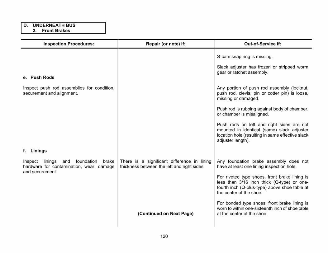
D. UNDERNEATH BUS 2. Front Brakes
Inspection Procedures: Repair (or note) if: Out-of-Service if:
e. Push Rods
Inspect push rod assemblies for condition, securement and alignment.
f. Linings
Inspect linings and foundation brake hardware for contamination, wear, damage and securement.
There is a significant difference in lining thickness between the left and right sides.
(Continued on Next Page)
S-cam snap ring is missing.
Slack adjuster has frozen or stripped worm gear or ratchet assembly.
Any portion of push rod assembly (locknut, push rod, clevis, pin or cotter pin) is loose, missing or damaged.
Push rod is rubbing against body of chamber, or chamber is misaligned.
Push rods on left and right sides are not mounted in identical (same) slack adjuster location hole (resulting in same effective slack adjuster length).
Any foundation brake assembly does not have at least one lining inspection hole.
For riveted type shoes, front brake lining is less than 3/16 inch thick (Q-type) or one-fourth inch (Q-plus-type) above shoe table at the center of the shoe.
For bonded type shoes, front brake lining is worn to within one-sixteenth inch of shoe table at the center of the shoe.
120

D. UNDERNEATH BUS 2. Front Brakes
Inspection Procedures: Repair (or note) if: Out-of-Service if:
g. Disc Brake Pads
Inspect disc brake pads for contamination, wear, damage and securement.
There is significant difference in pad thickness between the left and right sides of the bus.
(Continued on Next Page)
Front brake lining is worn to within one-sixteenth inch of any rivet.
Lining is broken, cracked or loose on shoe.
Lining is not proper size.
Friction surface is contaminated with oil, grease or brake fluid.
There is any shimming material between lining and shoe.
Shoe table or webbing is cracked or damaged.
There is any loose, damaged or missing foundation brake hardware within the drum.
Pad surface is contaminated, cracked, broken or missing.
Thickness of friction material is less than one-eighth inch.
Pad wear is uneven end-to-end exceeding 3/32 inch.
Difference between the inboard and outboard pads on one side is greater than one-eighth inch.
121
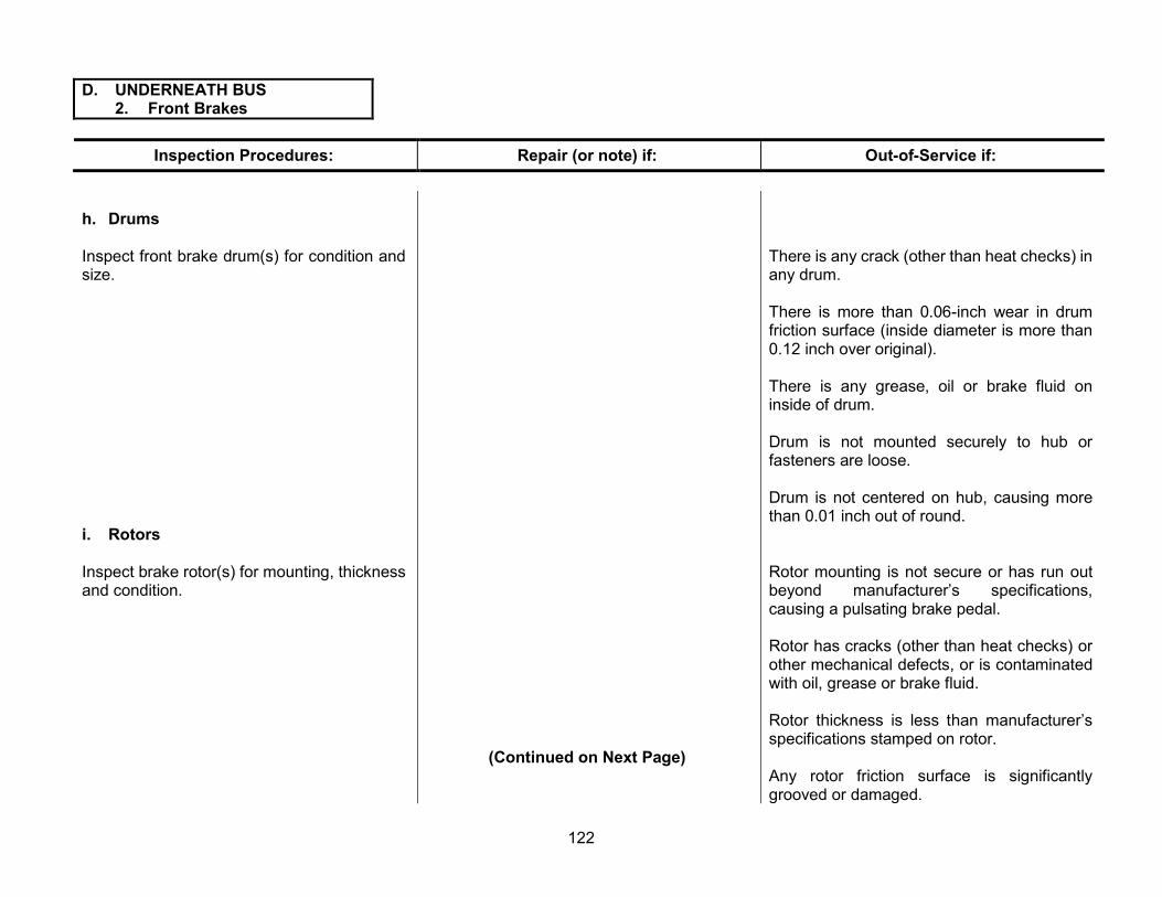
D. UNDERNEATH BUS 2. Front Brakes
Inspection Procedures: Repair (or note) if: Out-of-Service if:
h. Drums
Inspect front brake drum(s) for condition and size.
i. Rotors
Inspect brake rotor(s) for mounting, thickness and condition.
(Continued on Next Page)
There is any crack (other than heat checks) in any drum.
There is more than 0.06-inch wear in drum friction surface (inside diameter is more than 0.12 inch over original).
There is any grease, oil or brake fluid on inside of drum.
Drum is not mounted securely to hub or fasteners are loose.
Drum is not centered on hub, causing more than 0.01 inch out of round.
Rotor mounting is not secure or has run out beyond manufacturer’s specifications, causing a pulsating brake pedal.
Rotor has cracks (other than heat checks) or other mechanical defects, or is contaminated with oil, grease or brake fluid.
Rotor thickness is less than manufacturer’s specifications stamped on rotor.
Any rotor friction surface is significantly grooved or damaged.
122

D. UNDERNEATH BUS 2. Front Brakes
Inspection Procedures: Repair (or note) if: Out-of-Service if:
j. Wheel Cylinders or Calipers
Inspect wheel cylinders or calipers for seepage, leaks, mounting and condition.
Note: See page 131 for definitions of fluid “leaks” and “seepage.”
Any wheel cylinder or caliper dust boot is damaged or missing.
(Continued on Next Page)
Any wheel cylinder or caliper is seeping, leaking, not securely mounted, or has loose or missing fasteners.
There is uneven lining or pad wear, rotor or drum damage, evidence of dragging or other evidence that any wheel cylinder or caliper may be sticking.
123

D. UNDERNEATH BUS 2. Front Brakes
Inspection Procedures:
k. Adjust Brakes
1) Any brakes (air or hydraulic) without automatic adjusting capabilities must be adjusted at each inspection using the following procedure:
a) Tighten brake adjuster until wheel locks up.
b) Back off brake adjuster until there is a very slight drag on friction surfaces.
2) For all Manual Slack Adjuster (MSA) equipped S-cam brakes, each brake chamber push rod travel must be measured and brakes must be adjusted at every required inspection at all wheel positions (see figure 15, page 126). Push rod travel must not exceed limits shown in chart 13 on page 127.
Repair (or note) if:
(Continued on Next Page)
Out-of-Service if:
Any condition prevents proper adjustment of manual adjusting brakes.
Any MSA-equipped S-cam cannot be adjusted to bring push rod travel within limits shown in chart 13 on page 127 of this manual.
124

D. UNDERNEATH BUS 2. Front Brakes
Inspection Procedures: Repair (or note) if: Out-of-Service if:
3) Do not adjust ASA-equipped brakes. Push-rod travel must be measured and must not exceed limits shown in chart 13 on page 127. If the push rod travel measurement exceeds the limits, the foundation brakes, slack adjusters, push rods and chambers must all be inspected and repaired or replaced, if found defective. Correctly installed and properly working ASAs should keep the brakes in adjustment throughout the life of the linings.
Any ASA is damaged or malfunctioning, or push rod travel exceeds the limits shown in chart 13, page 127.
Figure 14
S-cam Bushing Up-and-Down Play S-cam In-and-Out Play
125

Figure 15
PROCEDURE FOR MEASURING PUSH ROD TRAVEL
Brake chamber push rod travel shall not exceed maximum stroke specifications. Performance of the brake push-rod travel inspection requires full application of the brake, with a minimum of 80 to 90 psi of application air pressure.
CAUTION: Chock wheels before commencing this inspection, as vehicle emergency brake(s) must be off.
Note: When brakes are properly adjusted and fully applied, the slack adjuster should be at an angle of 90° measured from centerline of adjuster to push rod.
Apply brakes and measure distance of mark from chamber.
With brakes off, mark push rod at chamber.
Note: Refer to chart 13, page 127 for maximum push rod travel (stroke) at which brake adjustment is required.
126

CHART 13 Dimensions in inches
Type Maximum Stroke
Maximum stroke with brakes adjusted
Maximum stroke at which brakes should be
adjusted
6 1-5/8 1-1/4
9 1-3/4 1-3/8
12 1-3/4 1-3/8
16 2-1/4 Should be as short as 1-3/4
20 2-1/4 possible without brakes
dragging 1-3/4
24 2-1/4 1-3/4
30 2-1/2 2
36 3 2-1/4
CLAMP TYPE BRAKE CHAMBER
16 2-1/2 2
20 2-1/2 Should be as short as 2
24 2-1/2 possible without brakes 2
24 3 dragging 2-1/2
30 3-3/8 2-1/2
"LONG STROKE" CLAMP-TYPE BRAKE CHAMBER
9 2 1-5/8
12 2 1-5/8
16 2-1/2 2
20 2-1/2 Should be as short as 2
24 2-1/2 possible without brakes
dragging 2
30 3 2-1/2
36 3-1/2 2-3/4
50 4 3-1/4
ROTOCHAMBER
12 1-3/8 1-3/8
16 1-1/2 Should be as short as 1-3/4
20 1-5/8 possible without brakes 1-3/4
24 1-3/4 dragging 1-3/4
30 1-7/8 2
AIR DISC BRAKES
127

D. UNDERNEATH BUS 3. Engine Mounts, Transmission Mounts and Starter Mounting
Inspection Procedures: Repair (or note) if: Out-of-Service if:
a. Engine/Transmission Mounts
Inspect engine and transmission mounts for condition and securement.
b. Starter Mounting
Inspect starter for securement and condition.
Any mounting fasteners are loose, missing or broken.
Any mount is cracked or has deteriorated rubber.
Any starter-mounting bolt, stud or nut is loose, damaged, broken or missing.
Starter is damaged or loose.
Any starter cables are loose or bare, or any positive cable could short to ground.
128

D. UNDERNEATH BUS 4. Transmission
Inspection Procedures: Repair (or note) if: Out-of-Service if:
a. Transmission Bolts
Inspect transmission assembly and mounting fasteners for condition and securement.
b. Linkage
Inspect transmission linkage for routing, condition and securement.
c. Lines
Inspect transmission lines for securement, routing and condition.
Any transmission assembly fastener is loose, missing or damaged.
Modulator, Throttle Valve (TV) cable or vacuum hose is routed where it is subject to excessive heat or abrasion.
Any linkage hardware or fasteners are loose.
Modulator or TV cable is exposed or casing is damaged.
Vacuum modulator hose is deteriorated or loose.
Any transmission line is unsecured.
(Continued on Next Page)
Transmission is not mounted securely to flywheel housing.
There is any indication that any torque converter bolt is loose or missing.
Linkage is bent, damaged, binding or severely misadjusted.
Any linkage hardware or fasteners are missing, or linkage is damaged, causing a sticking or binding condition.
Vacuum-modulator hose is leaking or not connected.
Any transmission line is improper type, crimped, improperly routed, damaged or leaking.
129
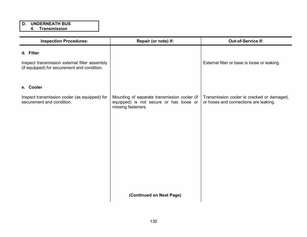
D. UNDERNEATH BUS 4. Transmission
Inspection Procedures: Repair (or note) if: Out-of-Service if:
d. Filter
Inspect transmission external filter assembly (if equipped) for securement and condition.
e. Cooler
Inspect transmission cooler (as equipped) for securement and condition.
Mounting of separate transmission cooler (if equipped) is not secure or has loose or missing fasteners.
(Continued on Next Page)
External filter or base is loose or leaking.
Transmission cooler is cracked or damaged, or hoses and connections are leaking.
130

D. UNDERNEATH BUS 5. Fluid Leaks
Note: Leaks and Seepage are types of fluid loss defined as: Leak: Enough fluid loss to cause dripping fluid. Leaking fluid can also be slung from rotating assemblies. Seepage: Fluid loss that may cause dampness or staining, but not dripping or slung fluid.
Inspection Procedures: Repair (or note) if: Out-of-Service if:
a. Oil
Inspect for engine oil leaks at all locations and determine severity.
b. Coolant
Inspect all locations for coolant leaks.
Engine oil is seeping or slightly leaking onto any location except exhaust system.
Engine oil leakage is causing deterioration of any rubber parts, such as steering linkage boots, hoses, etc.
There is a drip shield installed to divert leaking oil from the exhaust system.
There is coolant seeping at radiator, hoses, engine oil cooler, thermostat housing, head gaskets, freeze plugs, reservoir, water pump or other locations.
Engine oil leakage is excessive.
Engine oil is dripping, slinging or being blown on to any portion of exhaust system.
Coolant leakage is excessive.
(Continued on Next Page)
131

D. UNDERNEATH BUS 5. Fluid Leaks
Inspection Procedures: Repair (or note) if: Out-of-Service if:
c. Transmission
Inspect for transmission fluid leaks at all locations and determine severity.
Note: See page 131 for definitions of fluid “leaks” and “seepage.”
Transmission fluid is seeping or slightly leaking on to any location except exhaust system.
Transmission fluid is causing deterioration of any rubber parts, such as steering linkage boots, hoses, etc.
Transmission fluid leakage is excessive.
Transmission fluid is dripping on any portion of exhaust system.
d. Power Steering
Inspect for power steering fluid leaks at all locations and determine severity.
Power steering fluid is seeping.
Power steering fluid is causing deterioration of any rubber parts, such as steering linkage boots, hoses, etc.
Power steering fluid is leaking.
Power steering reservoir cap or dipstick is missing.
132

D. UNDERNEATH BUS 6. Fuel and DEF Tank
Inspection Procedures: Repair (or note) if: Out-of-Service if:
a. Leaks
Inspect fuel and DEF tank assembly for leaks.
Note: See page 131 for definitions of fluid “leaks” and “seepage.”
b. Mounting
Inspect fuel and DEF tank mounting system and barrier (if equipped) for securement and condition.
(Continued on Next Page)
There is any fuel or DEF leakage from the tank, sending unit, connections, vent or cap, or cap is missing.
Any tank is cracked.
Any hose connection is loose at the tank.
Any portion of tank mounting system (including support brackets, retaining straps and chassis frame) is missing, loose, cracked or broken.
Any tank mounting fasteners are loose or missing.
Barrier assembly (if required) is damaged, insecurely mounted or missing.
133
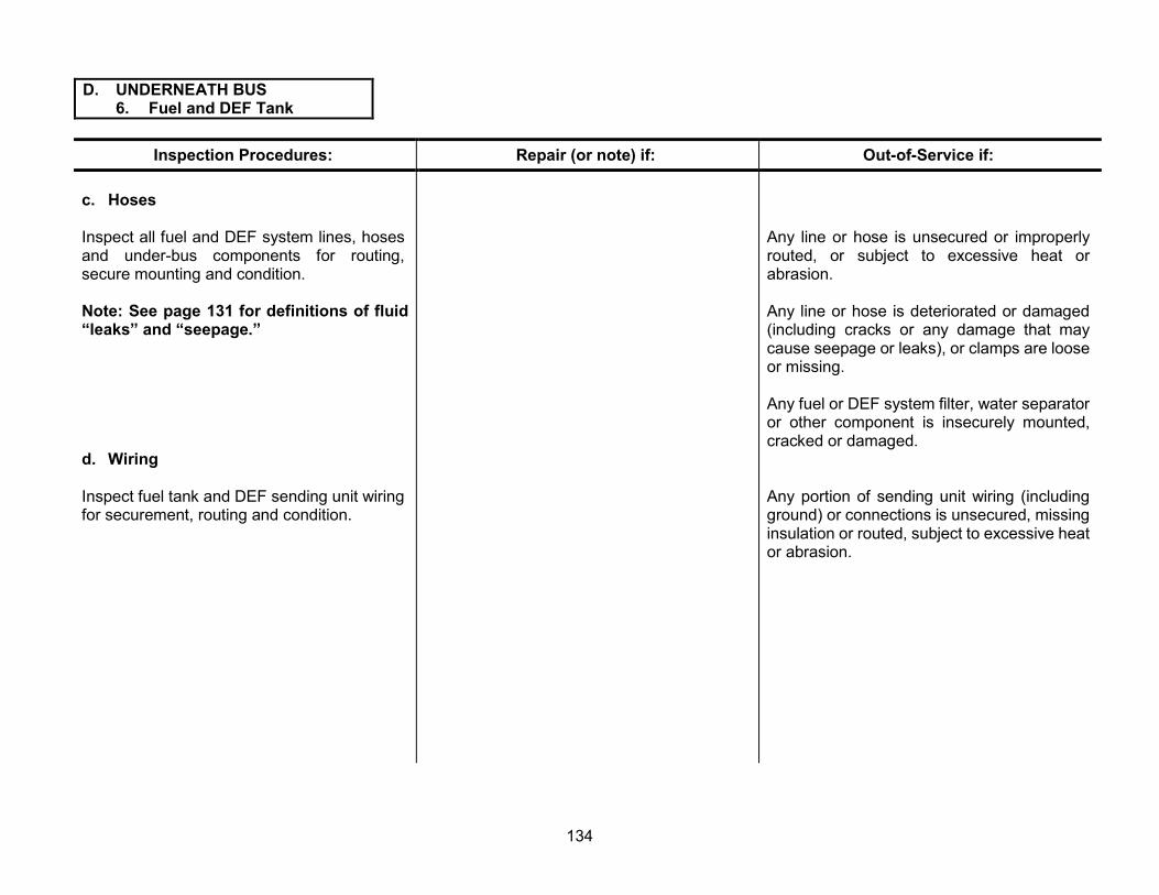
D. UNDERNEATH BUS 6. Fuel and DEF Tank
Inspection Procedures: Repair (or note) if: Out-of-Service if:
c. Hoses
Inspect all fuel and DEF system lines, hoses and under-bus components for routing, secure mounting and condition.
Note: See page 131 for definitions of fluid “leaks” and “seepage.”
d. Wiring
Inspect fuel tank and DEF sending unit wiring for securement, routing and condition.
Any line or hose is unsecured or improperly routed, or subject to excessive heat or abrasion.
Any line or hose is deteriorated or damaged (including cracks or any damage that may cause seepage or leaks), or clamps are loose or missing.
Any fuel or DEF system filter, water separator or other component is insecurely mounted, cracked or damaged.
Any portion of sending unit wiring (including ground) or connections is unsecured, missing insulation or routed, subject to excessive heat or abrasion.
134

D. UNDERNEATH BUS 7. Brake Equipment
Inspection Procedures: Repair (or note) if: Out-of-Service if:
a. Brake Lines
Inspect all brake hoses, lines and connections Any brake hose or line is unsecured. for routing, securement and condition.
Note: See page 131 for definitions of fluid “leaks” and “seepage.”
Note: External layer weather cracking only shall not be cause for rejection.
b. Brake Valves
Inspect all brake system valves for securement and condition.
c. Reservoir Mounting
Inspect reservoirs (air and vacuum tanks) for securement and condition.
(Continued on Next Page)
There is any audible air leak or visible hydraulic brake fluid seepage or leak.
Any brake line or hose is improperly routed, or subject to excessive heat or abrasion.
Any brake line or hose is deteriorated or damaged to the point that failure could occur (frayed, thin wall; rubber contaminated with oil; crimped; etc.).
Any brake line or hose connection is loose.
There are any audible air leaks or visible hydraulic fluid leaks or seepage from any brake valve.
Any brake valve is not mounted securely, is cracked or is damaged.
Any reservoir mounting, brackets, straps or fasteners are cracked, loose or missing.
135

D. UNDERNEATH BUS 7. Brake Equipment
Inspection Procedures: Repair (or note) if: Out-of-Service if:
d. Bleed Reservoirs
1) With air system fully charged, check manual operation of safety pressure relief valve.
2) Partially open manual petcock valve on the first (wet) tank.
3) Allow draining of any moisture (water) There is moisture in reservoir (desiccant-type or contamination. dryer only).
e. Anti-lock Brake System (ABS)
Perform a visual inspection of all ABS components, including wiring, connectors and controllers.
Safety relief valve leaks or does not release pressure.
There is excessive sludge or oil contamination in the reservoir (more than eight fluid ounces).
Reservoir leaks due to corrosion or is cracked.
Visual inspection reveals that ABS components are loose, damaged, missing, improperly routed or non-operational.
Note: Wiring from ABS controller(s) to wheel speed sensor(s) that has been abraded or otherwise damaged, exposing any wire conductor or grounding sheath, may cause failure of the antilock brake system. This damage is considered severe.
136

D. UNDERNEATH BUS 8. Driveline
Inspection Procedures: Repair (or note) if: Out-of-Service if:
a. Drive shafts
Inspect drive shafts for condition. Any driveshaft balancing weight (if originally equipped) is missing.
Driveshaft is assembled out of phase.
Any driveshaft is bent or seriously dented.
There are cracks or other damage that could cause structural failure.
b. U-Joints
Prior to lubrication, inspect U-joints or constant velocity (CV) joints (if equipped) for condition, phasing (alignment of joints), lubrication and presence of all hardware.
U-joints or CV joints are insufficiently lubricated or grease fitting is missing, clogged or not accessible.
(Continued on Next Page)
There is any missing hardware or fasteners in any U-joint or CV joint assembly.
Any U-joint has significant cross-shaft-to-bearing cup play, or CV joint has significant play.
Any U-joint or CV joint shows evidence of significant rusting of bearings.
Any bearing cup is loose in yoke.
Any U-joint is cracked or broken.
137

D. UNDERNEATH BUS 8. Driveline
Inspection Procedures: Repair (or note) if: Out-of-Service if:
c. Yokes
Inspect driveshaft yokes for condition and lubrication.
d. Hanger Bearings
Inspect hanger bearings and rubber insulators for condition and securement.
e. Guards
Inspect for presence and condition of driveshaft guards.
Driveshaft splines are not lubricated.
Dust cap on yoke is missing.
Grease fitting is missing or clogged.
Cork washer in dust cap is missing.
Hanger bearing rubber insulator is deteriorated, damaged or oil-soaked.
Hanger bearing support is misaligned.
Any driveshaft guard is bent or damaged.
Any yoke has significant play in splines.
Any yoke is cracked or damaged.
Bearing outer race is loose in insulator or inner race is loose on shaft.
There is significant play in hanger bearing.
There is any missing or damaged hardware or fasteners in hanger bearing or support assembly.
Any driveshaft guard is missing or has loose or damaged mounting fasteners.
(Continued on Next Page)
138

D. UNDERNEATH BUS 8. Driveline
Inspection Procedures: Repair (or note) if: Out-of-Service if:
f. Driveshaft Parking Brake
Inspect driveshaft parking brake assembly for condition, mounting, securement and adjustment of linings, drum, linkage and all other related hardware.
Lining is worn down to 2/32 inch from top of rivet head.
Lining is contaminated with grease or oil.
Lining is broken, cracked or loose.
Drum is cracked or has excessive heat damage or scoring of friction surface.
Any actuating or mounting hardware or fastener is damaged, loose or missing.
Parking brake is not adjusted per manufacturer’s specifications.
139

D. UNDERNEATH BUS 9. Rear Suspension
Inspection Procedures: Repair (or note) if: Out-of-Service if:
a. Axle Housing
Inspect axle housing for condition and leakage.
Note: See page 131 for definitions of fluid “leaks” and “seepage.”
b. Vent
Inspect condition of axle housing vent.
c. Differential
Inspect differential assembly for condition, lubricant level and leakage.
Note: See page 131 for definitions of fluid “leaks” and “seepage.”
Axle housing is seeping lubricant. Any portion of axle housing is cracked or bent.
Any portion of axle housing is leaking lubricant due to cracks, porous metal or defective welds.
There is any leakage at or around axle housing ends.
Vent cap is clogged. Axle vent is not functional or is missing.
Vent hose (if originally equipped) is cracked or missing.
Lubricant level is low. Differential gaskets or seals are leaking.
Differential gaskets or seals are seeping. There is no lubricant in the differential.
Any external differential hardware or fasteners are loose or missing.
(Continued on Next Page) Differential pinion yoke nut is loose or has endplay or side play exceeding manufacturer’s specifications.
140

D. UNDERNEATH BUS 9. Rear Suspension
Inspection Procedures: Repair (or note) if: Out-of-Service if:
d. Springs
Inspect rear springs for condition, securement There are any loose, missing, broken or worn and alignment. spring clips.
Any leaf spring or air-suspension ride height is less than manufacturer’s specifications.
Rubber frame bumper is missing.
e. U-Bolts
Inspect spring U-bolts for condition and Any U-bolt is misaligned. securement.
(Continued on Next Page)
Any leaf spring is broken or missing.
On any type spring assembly, airbag is damaged or leaking, or airlines and valving are damaged or leaking.
Air ride pivot pins and bushings are loose.
There is any misalignment of spring leaves or other evidence that centering pin is loose or broken.
Either rear leaf spring is worn to the point that suspension bottoming has damaged rubber frame bumper.
There is rust underneath U-bolt nuts, indicating possibility of looseness.
Any U-bolt, U-bolt seating plate, shock mount bracket or nut is loose, missing, cracked or stripped.
141

D. UNDERNEATH BUS 9. Rear Suspension
Inspection Procedures: Repair (or note) if: Out-of-Service if:
f. Shock Absorbers
Inspect rear shocks for condition and securement.
Note: See page 131 for definitions of fluid “leaks” and “seepage.”
g. Shackles
Inspect rear suspension shackles, spring hangers and hanger pinch bolts for condition and securement.
(Continued on Next Page)
Any shock is broken.
Any shock fails to function.
Any shock mounting or fastener is loose, missing, cracked or broken.
Any shock is leaking fluid.
Note: A very small amount of fluid staining at the shock-piston shaft seal area is normal due to the wiping function of the shaft seal. This does not indicate a leaking shock.
Any rear spring shackle or hanger is cracked or broken.
Any rear spring shackle/hanger is worn or any pinch bolt is stripped/missing, preventing the spring pin from being clamped tightly.
142

D. UNDERNEATH BUS 9. Rear Suspension
Inspection Procedures: Repair (or note) if: Out-of-Service if:
h. Pins and Bushings
Inspect rear spring pins and bushings for wear Any spring pin assembly will not accept and lubrication. See figure 13, page 117, for lubrication, or grease fitting is damaged or shackle type system on checking play in pins missing. and bushings. For other types of pin and bushing configurations, see manufacturer’s service manual.
(Continued on Next Page)
Inner sleeve on rubber type spring pin assemblies is worn through or rubber bushing is excessively worn (rubber is compacted or deteriorated, resulting in free play between rubber and spring eye or inner sleeve).
Rear spring pin bushing (metal type bushing) is worn through.
Total free play (up and down) of pin and bushing exceeds one-eighth inch for single pin type.
On system using two pins and bushings, combined free play exceeds one-fourth inch.
143

D. UNDERNEATH BUS 9. Rear Suspension
Inspection Procedures: Repair (or Note) if: Out-of-Service if:
i. Hangers
Inspect hangers for mounting and condition.
j. Seals
Inspect rear wheel seals for condition and leakage.
Note: See page 131 for definitions of fluid “leaks” and “seepage.”
k. Wheel Bearings
Inspect rear wheel bearings for condition and proper adjustment of bearings.
1) Raise rear wheels (wheels unloaded) and release parking brake.
2) Grasp tire and attempt to rock wheel assembly to check for movement.
There is seepage of oil or grease around axle flange or wheel seal.
Note: Rear wheel bearing in-out play should be 0.000 inches.
Any spring hanger or bracket is cracked or broken, or any mounting fastener is loose or missing.
Either rear wheel seal or axle flange is damaged or leaking.
Any axle flange stud or nut is loose or missing.
There is any detectable looseness or roughness in rear wheel bearings.
144

D. UNDERNEATH BUS 10. Rear Brakes
Inspection Procedures: Repair (or note) if: Out-of-Service if:
a. Hoses
Inspect rear brake flexible hoses for condition, securement and routing.
Note: See page 131 for definitions of fluid “leaks” and “seepage.”
b. Lines
Inspect air and hydraulic brake lines for Brake line bracket(s) or securement system is routing, securement and condition. loose or missing.
Note: See page 131 for definitions of fluid “leaks” and “seepage.”
(Continued on Next Page)
Any rear brake flex hose or connection is seeping, leaking fluid or leaking air pressure.
Any rear brake flex hose is kinked, collapsed, bulging, has damaged plies or is damaged below outer covering.
Any rear brake flex hose supporting brackets are damaged or have loose fasteners.
Any rear brake flex hose is rubbing on or routed against other components.
Any brake line is bent, crimped or damaged, restricting air pressure or hydraulic fluid.
Any brake line or connection is seeping or leaking hydraulic fluid or leaking air pressure.
Any brake line is rubbing on other components or is abraded.
Any brake line is not of OEM material, size or type.
145

D. UNDERNEATH BUS 10. Rear Brakes
Inspection Procedures: Repair (or note) if: Out-of-Service if:
c. Chambers
Inspect rear brake chamber assemblies for securement, condition and proper size.
d. Slacks
Inspect slack adjusters and S-cam Slack adjuster is mounted so that adjuster bolt assemblies for wear, condition, operation and is facing chamber. securement.
Note: See section D.10.k, page 152-153, on brake adjustment for procedure to check operation of ASA.
(Continued on Next Page)
Any rear chamber-mounting bracket or hardware is cracked, bent, broken or missing.
Any rear brake chamber or mounting fastener is damaged, loose, missing or of the wrong type.
Either rear chamber is not OEM size and stroke length.
Any portion of slack adjuster or S-cam is missing, broken, cracked, worn beyond limits or improperly installed.
S-cam shaft and/or S-cam bushing total wear (up and down) is greater than 0.04 inch (see figure 14, page 125).
S-cam In-and-Out endplay is more than 0.06 inch (see figure 14, page 125).
S-cam snap ring is missing.
Slack adjuster has frozen or stripped worm gear or ratchet assembly.
146
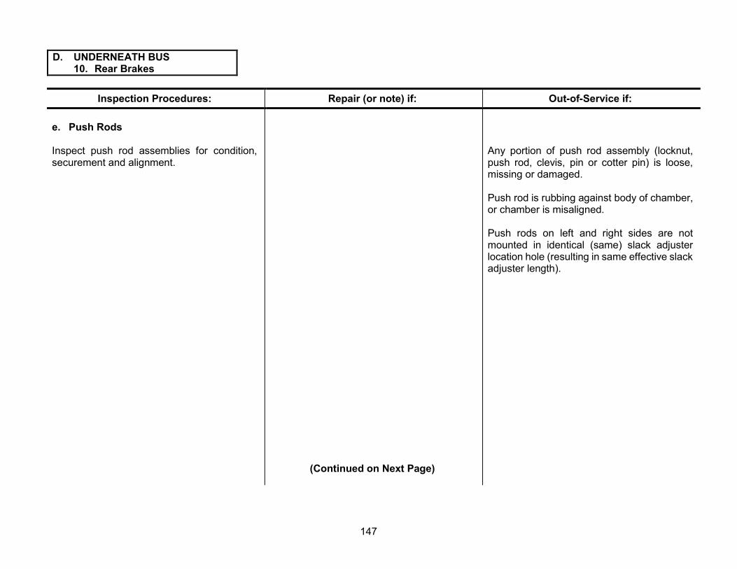
D. UNDERNEATH BUS 10. Rear Brakes
Inspection Procedures: Repair (or note) if: Out-of-Service if:
e. Push Rods
Inspect push rod assemblies for condition, securement and alignment.
(Continued on Next Page)
Any portion of push rod assembly (locknut, push rod, clevis, pin or cotter pin) is loose, missing or damaged.
Push rod is rubbing against body of chamber, or chamber is misaligned.
Push rods on left and right sides are not mounted in identical (same) slack adjuster location hole (resulting in same effective slack adjuster length).
147

D. UNDERNEATH BUS 10. Rear Brakes
Inspection Procedures: Repair (or note) if: Out-of-Service if:
f. Linings
Inspect linings and foundation brake hardware for contamination, wear, damage and securement.
There is a significant difference in lining thickness between the left and right sides.
Rear brake lining is less than five-sixteenths inch thick at center of shoe (on brake blocks with original three-fourths inch thickness).
(Continued on Next Page)
Any foundation brake assembly does not have at least one lining inspection hole.
For riveted type shoes, rear brake lining is less than one-fourth inch thick at center of shoe (on brake blocks with original three-fourths inch thickness).
Rear brake lining is worn to within one-sixteenth inch of any rivet.
For bonded type shoes, rear brake lining is worn to within one-sixteenth inch of shoe table (at center of shoe).
Lining is broken, cracked or loose on shoe.
Lining is not proper size.
Friction surface is contaminated with oil, grease or brake fluid.
There is any shimming material between lining and shoe.
Shoe table or webbing is cracked or damaged.
There is any loose, damaged or missing foundation brake hardware within the drum.
148

D. UNDERNEATH BUS 10. Rear Brakes
Inspection Procedures: Repair (or note) if: Out-of-Service if:
g. Disc Brake Pads
Inspect disc brake pads for contamination, wear, damage and securement
There is a significant difference in pad thickness between the left and right sides of the bus.
(Continued on Next Page)
Pad surface is contaminated, cracked, broken or missing.
Thickness of friction material is less than one-eighth inch.
Pad wear is uneven end-to-end exceeding 3/32 inch.
Difference between the inboard and outboard pads is greater than one-eighth inch.
149
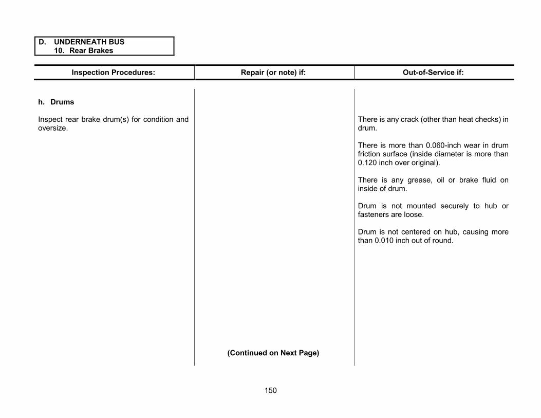
D. UNDERNEATH BUS 10. Rear Brakes
Inspection Procedures: Repair (or note) if: Out-of-Service if:
h. Drums
Inspect rear brake drum(s) for condition and oversize.
(Continued on Next Page)
There is any crack (other than heat checks) in drum.
There is more than 0.060-inch wear in drum friction surface (inside diameter is more than 0.120 inch over original).
There is any grease, oil or brake fluid on inside of drum.
Drum is not mounted securely to hub or fasteners are loose.
Drum is not centered on hub, causing more than 0.010 inch out of round.
150

D. UNDERNEATH BUS 10. Rear Brakes
Inspection Procedures: Repair (or note) if: Out-of-Service if:
i. Rotors
Inspect rear brake rotor(s) for mounting, thickness and condition.
Rotor is not secure or has run-out beyond manufacturer’s specifications, causing a pulsating brake pedal.
Rotor has cracks (other than heat checks) or other mechanical defects or is contaminated with oil, grease or brake fluid.
Rotor thickness is less than manufacturer’s specifications stamped on rotor.
Any rotor friction surface is significantly grooved or damaged.
j. Wheel Cylinders or Calipers
Inspect wheel cylinder(s) or caliper(s) for seepage, leaks, mounting and condition.
Note: See page 131 for definitions of fluid “leaks” and “seepage.”
Any wheel cylinder or caliper dust boot is damaged or missing.
(Continued on Next Page)
Any wheel cylinder or caliper is seeping, leaking, not securely mounted or has loose or missing fasteners.
There is uneven lining or pad wear, rotor or drum damage, evidence of dragging or other evidence that any wheel cylinder or caliper may be sticking.
151

D. UNDERNEATH BUS 10. Rear Brakes
Inspection Procedures: Repair (or note) if: Out-of-Service if:
k. Adjust Brakes
1) Any brakes (air or hydraulic) without automatic adjusting capabilities must be adjusted at each inspection using the following procedure:
a) Tighten brake adjuster until wheel locks up.
b) Back off brake adjuster until there is very slight drag on friction surfaces.
2) MSA equipped brakes must be adjusted at every required inspection at all wheel positions (see f
igure 15, page 126). Push rod travel must not exceed limits shown in chart 13 on page 127.
Any damage or condition prevents proper adjustment of manual adjusting brakes.
Any MSA-equipped brakes cannot be adjusted to bring push rod travel within limits shown in chart 13 on page 127 of this manual.
(Continued on Next Page)
152

D. UNDERNEATH BUS 10. Rear Brakes
Inspection Procedures: Repair (or note) if: Out-of-Service if:
3) Do not adjust brakes equipped with ASAs. Push rod travel must be measured and must not exceed limits shown in chart 13 on page 127. If the push rod travel measurement exceeds the limits, the foundation brakes, slack adjusters, push rods and chambers must all be inspected and repaired or replaced, if found defective. Correctly installed and properly working ASAs should keep the brakes in adjustment throughout the life of the linings.
Any ASA is damaged or malfunctioning or push rod travel exceeds the limits shown in chart 13, page 127.
153

D. UNDERNEATH BUS 11. Body Securement and Structure
Inspection Procedures: Repair (or note) if: Out-of-Service if:
a. Body Hold-downs
Inspect for securement and condition of all body hold-downs, chassis cowl mounts and frame pads. Body hold-downs include any J-bolt, U-bolt or clamp type hold-down used to secure body to chassis frame.
b. Floor
Inspect condition of floor structure, sills and braces.
One or two body hold-downs are loose or misaligned, or there are any cracks or stripped fasteners at floor securement points.
Padding between frame rails and floor sills is misaligned.
Any OEM installed body hold-down or cowl mount is missing.
Three or more body hold-downs are loose, cracked, stripped, misaligned or have missing hardware.
There are any minor cracks in floor sills, braces or welds.
There are any holes or cracks in floor sheet metal, creating an opening to the passenger compartment.
Entire cross-section of any floor sill or brace is broken.
There is any broken weld or mounting of a floor sill or brace, resulting in complete separation of more than one foot in length.
(Continued on Next Page)
There is any broken weld or loose mounting of the floor bracing, K-member, etc., at the front under the driver, center and step well areas (or “cab” area).
154

D. UNDERNEATH BUS 11. Body Securement and Structure
Inspection Procedures: Repair (or note) if: Out-of-Service if: c. Outriggers
Inspect body outriggers and hardware for condition and securement.
d. Braces
Inspect for condition and securement of all chassis and body braces.
e. Skirts
Inspect body skirts (and luggage compartments, if equipped) for securement and condition.
f. Mud Flaps
Inspect for required mud flaps and splash shielding on buses with skirt-mounted A/C condensers.
g. Frame Rails
Inspect condition of chassis frame rails, cross members and all hardware attachment points.
There are any minor cracks in bracing underneath the body.
Body skirt, skirt brace or luggage compartment has minor cracks, broken sheet metal or mounting points.
Any mud flap is missing.
Any OEM-installed outrigger is missing, or body outrigger is cracked or has loose or missing hardware.
Any bumper brace is broken, cracked or missing.
Luggage compartment door-latch, hinge or lock is sticking, damaged or malfunctioning.
Any mud flap is loose or damaged and may detach while bus is in route.
There is any crack in either frame rail or any cross-member.
There is any loose or missing rivet or other fastener securing a cross-member to the frame.
155

D. UNDERNEATH BUS 12. Exhaust System
Inspection Procedures: Repair (or note) if: Out-of-Service if:
a. Exhaust Leaks
Inspect for condition and securement. With engine running at operating temperature, inspect exhaust system for leaks.
b. Mounting
Inspect mounting of the exhaust system.
c. Mufflers and DPF
Inspect condition of the muffler and DPF.
d. DEF Components
Inspect DEF components.
e. Tailpipe
Inspect condition of tailpipe and ensure that it extends beyond the rear bumper and exits to the left of the left frame rail (since 1998). If equipped with regenerative type exhaust system or for type D rear engine buses, see 2008 specifications for tailpipe exceptions.
There is any physical damage to exhaust system, not restricting flow or causing leaks.
Any leakage is audible or can be felt around any portion of the exhaust system including manifold, pipe sections or any junction.
Any exhaust system hanger is not securely mounted.
Any exhaust pipe or clamp is loose.
Any exhaust hanger is missing, broken or detached from exhaust system or frame mounting point.
The muffler or DPF is leaking, restricted or damaged.
DEF tank lines or injector is loose, damaged or leaking fluid.
The tailpipe is cracked.
There is other significant physical damage to the tailpipe.
The tailpipe is leaking, or does not extend to at least the rear outer surface of the rear bumper, or the tailpipe extends more than two inches beyond the rear outer surface of the rear bumper (see figure 16 on page 157), or the tailpipe does not exit to the left of the left frame rail.
156
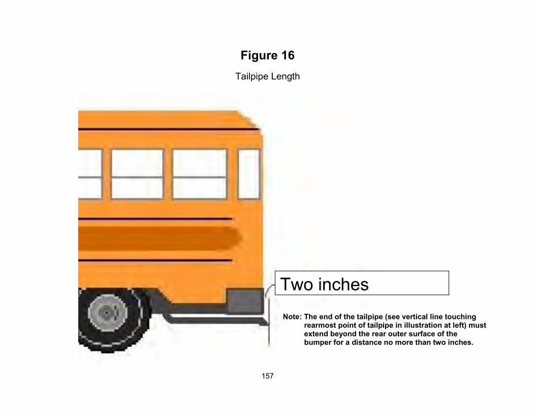
maximum
Figure 16 Tailpipe Length
Note: The end of the tailpipe (see vertical line touching rearmost point of tailpipe in illustration at left) must extend beyond the rear outer surface of the bumper for a distance no more than two inches.
Two inches
157

D. UNDERNEATH BUS 13. Wheels and Tires
Inspection Procedures: Repair (or note) if: Out-of-Service if:
a. Tread Depth
Inspect and measure all tires for tread depth and record measurements on inspection form.
(Continued on Next Page)
Tread depth of any tire is less than: Front: 4/32 inch Rear: 2/32 inch
measured at three points spaced equally around the circumference of the tire in the same major tread groove. Do not measure at wear bars. Measurements for all three points must fall below the limits above before tire is required to be out-of-service. Measurements shall be taken at the most worn major tread groove of the tire.
Any single point of the most worn major tread groove of any tire measures less than:
Front: 2/32 inch Rear: 1/32 inch
There is evidence of any regrooved tire.
Any front tire is recapped or regrooved.
There is evidence that any tire has been regrooved using a procedure not approved by tire manufacturer or dealer.
158

D. UNDERNEATH BUS 13. Wheels and Tires
Inspection Procedures: Repair (or note) if: Out-of-Service if:
b. Pressure
With tires cold, check pressures of all tires and record measurements on the inspection form.
c. Damage
Inspect for damage to wheels and tires.
Note: Weather cracking only shall not be cause for rejection.
There is foreign material in the tire tread that could cause damage or loss of air pressure.
Pressure in any tire is lower than 20 percent below the maximum cold inflation pressure stated on sidewall of the tire.
Pressure in any tire is higher than 5 percent above the maximum cold inflation pressure stated on sidewall of the tire.
There is greater than 20 percent difference in pressure between any tires on a particular axle.
There are any cuts, abrasions or other damage to tire sidewall, resulting in exposed or damaged cord.
There is any evidence of separation, bulges (other than normal manufacturer bulge) or other damage within the carcass of the tire.
Any cracks run around the bead or sidewall of the tire.
(Continued on Next Page)
159

D. UNDERNEATH BUS 13. Wheels and Tires
Inspection Procedures: Repair (or note) if: Out-of-Service if:
Any valve cap is missing.
There are minor dents or bends in a rim.
d. Matching
Inspect for matching of tire construction, design, size and load rating on each axle.
(Continued on Next Page)
Retreaded tires have any separation of the tire tread from the tire carcass that could result in tire or tread failure.
Any valve stem is damaged or misaligned so that tire cannot be filled with air.
Any damage to the lock ring assembly or groove of a multi-piece rim that could cause the lock ring not to seat fully.
There are any cracks or breaks at the lugholes or any other part of a rim or cast spokes.
There are any dents, bends or non-OEM welds to a rim.
There is mismatching of inner and outer dual tire diameters greater than three-eighths inch.
There is any tire marked for use other than highway use.
Any tire is not of proper type, size and minimum load rating according to Florida Specifications.
160

D. UNDERNEATH BUS 13. Wheels and Tires
Inspection Procedures: Repair (or note) if: Out-of-Service if:
e. Alignment
Inspect tires for evidence of proper alignment. Any tire is feather-edged, cupped or has uneven tread wear.
Lateral run-out of any tire/rim assembly exceeds one-fourth inch.
f. Wheel Hardware
1) Inspect for presence, type, condition and securement of all wheel hardware.
2) Check for proper spacing of rear dual wheels and tires (proper spacer width).
Not all tires on an axle are of same type (i.e., lug or rib) and size.
Radial and bias ply tires are intermixed on the same axle.
Tires/wheels are grossly misaligned, affecting steering control.
There is improper matching of rims and lock rings.
There is evidence of slippage of wheel assembly on cast spoke hub.
Stud holes are elongated.
Any wheel nut, stud or clamp is loose, or there is rust or corrosion, indicating possible looseness.
(Continued on Next Page)
161
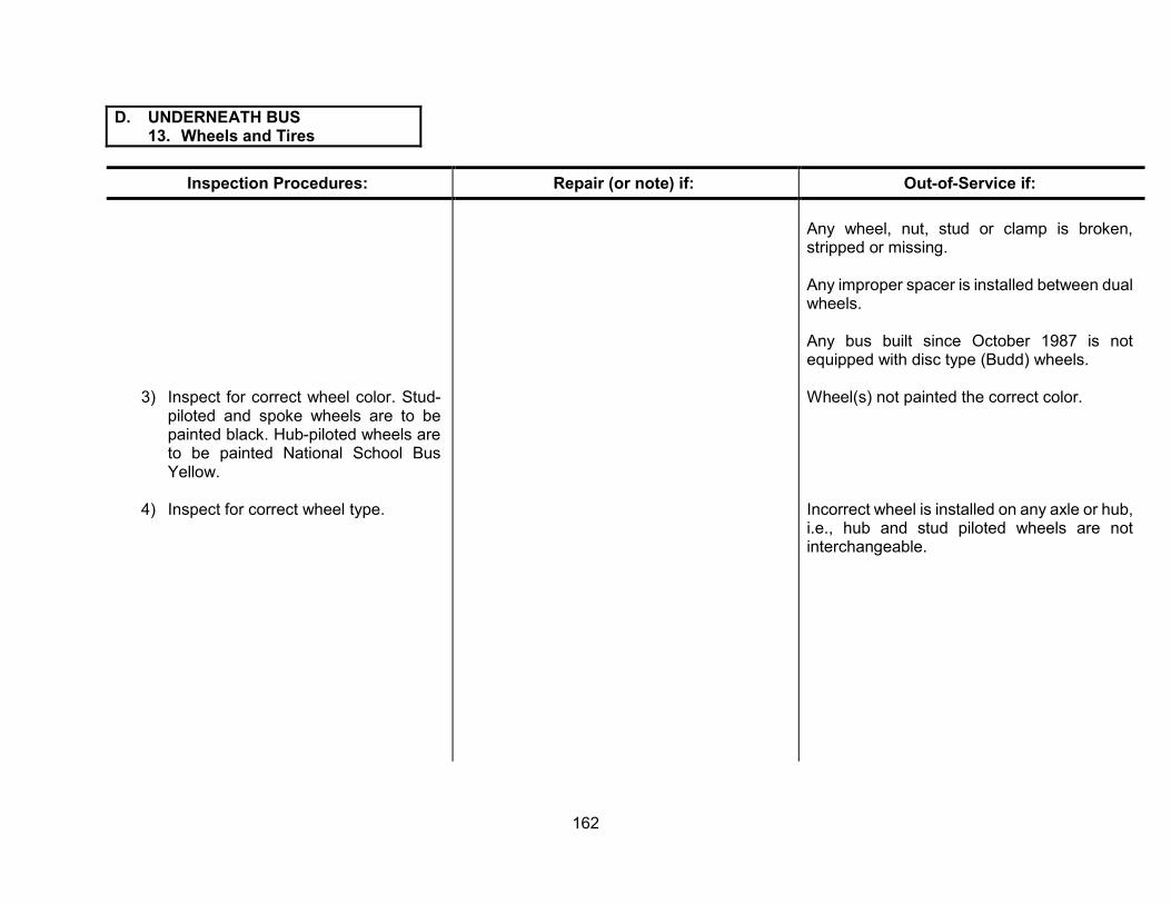
D. UNDERNEATH BUS 13. Wheels and Tires
Inspection Procedures: Repair (or note) if: Out-of-Service if:
3) Inspect for correct wheel color. Stud-piloted and spoke wheels are to be painted black. Hub-piloted wheels are to be painted National School Bus Yellow.
4) Inspect for correct wheel type.
Any wheel, nut, stud or clamp is broken, stripped or missing.
Any improper spacer is installed between dual wheels.
Any bus built since October 1987 is not equipped with disc type (Budd) wheels.
Wheel(s) not painted the correct color.
Incorrect wheel is installed on any axle or hub, i.e., hub and stud piloted wheels are not interchangeable.
162

E. LUBRICATION AND MAINTENANCE (OPTIONAL)
Inspection Procedures: Repair (or note) if: Out-of-Service if:
This section of the form is for the convenience of school districts. School districts should implement their own lubrication and maintenance policies and procedures.
(Continued on Next Page)
163

E. LUBRICATION AND MAINTENANCE (OPTIONAL)
Inspection Procedures: Repair (or note) if: Out-of-Service if:
164

F. ROAD TEST 1. Brake Performance
Inspection Procedures: Repair (or note) if: Out-of-Service if:
a. Parking Brake
Check for proper operation of parking brake as follows:
Apply parking brake. Place automatic transmission gear selector in drive and speed up the engine to a fast idle (approximately 1,200 RPM). Vehicle should not move forward.
b. Stopping Distance and Equalization
1) Stopping distance
The following stopping distance requirements should be met when stopping the vehicle on a level, dry, smooth, hard surface that is free from loose material from a speed of 20 mph:
a) Decelerometer reading (feet per second per second) minimum of 14.
Note: Buses equipped with Rear Diesel Vehicle moves forward. Engine and Allison World Transmission should be checked at 900 RPM.
Decelerometer reading is close to 14, but Decelerometer reading is less than 14. within acceptable limits.
(Continued on Next Page)
F. ROAD TEST 1. Brake Performance
165
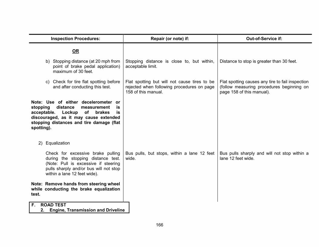
Inspection Procedures: Repair (or note) if: Out-of-Service if:
OR
b) Stopping distance (at 20 mph from point of brake pedal application) maximum of 30 feet.
Stopping distance acceptable limit.
is close to, but within, Distance to stop is greater than 30 feet.
c) Check for tire flat spotting before and after conducting this test.
Flat spotting but will not cause tires to be rejected when following procedures on page 158 of this manual.
Flat spotting causes any tire to fail inspection (follow measuring procedures beginning on page 158 of this manual).
Note: Use of either decelerometer or stopping distance measurement is acceptable. Lockup of brakes is discouraged, as it may cause extended stopping distances and tire damage (flat spotting).
2) Equalization
Check for excessive brake pulling during the stopping distance test. (Note: Pull is excessive if steering pulls sharply and/or bus will not stop within a lane 12 feet wide).
Bus pulls, wide.
but stops, within a lane 12 feet Bus pulls sharply and will not stop within a lane 12 feet wide.
Note: Remove hands from steering wheel while conducting the brake equalization test.
F. ROAD TEST 2. Engine, Transmission and Driveline
166

Inspection Procedures: Repair (or note) if: Out-of-Service if:
a. Engine Performance & Governor
Check for starting, color and quantity of exhaust smoke, proper idle, stalling, missing/skipping or hesitation, performance when accelerating and shutdown of engine.
b. Automatic Transmission
Check operation of shifter and transmission.
Engine will not start, is difficult to start or will not shut down.
Engine hesitates upon acceleration, stalls, misfires or performs poorly.
Any engine/emissions system warning lights or alarms are on, indicating a mechanical safety condition.
Up and down shifting is excessive, or shifts are hard.
Transmission will not shift up and down through all gears.
Transmission is slipping or noisy.
Shift points are not within manufacturer’s specifications.
F. ROAD TEST 3. Steering and Handling
167
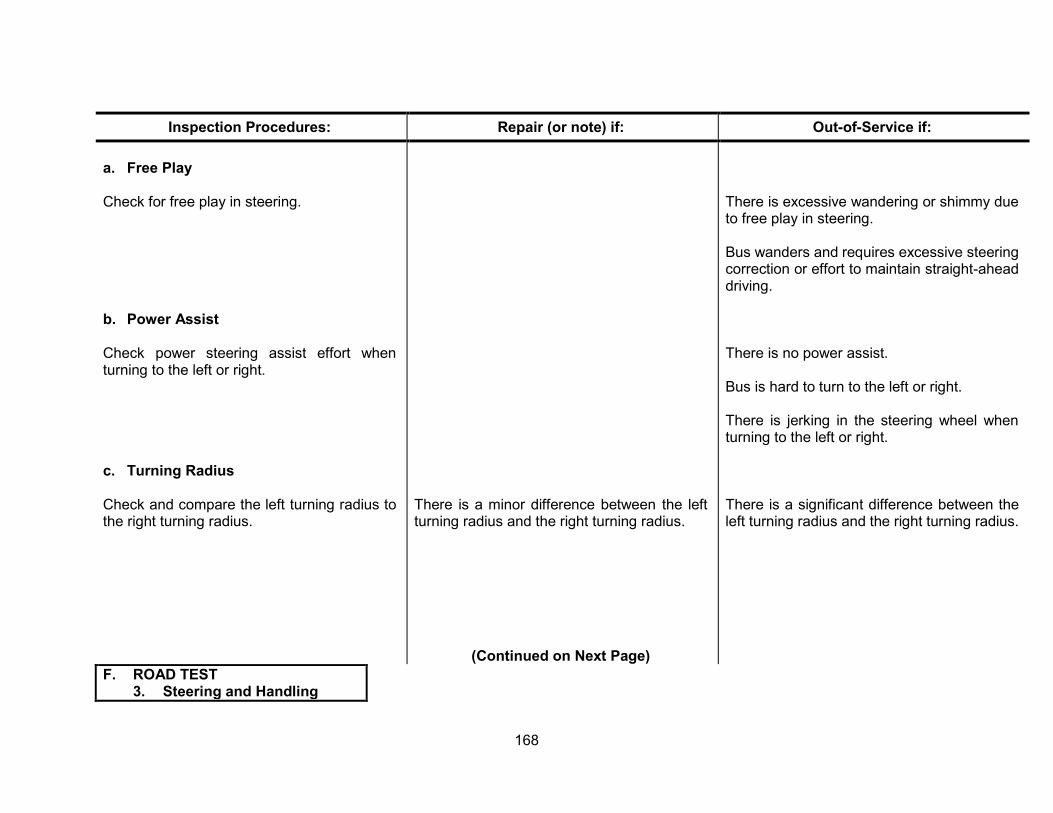
Inspection Procedures: Repair (or note) if: Out-of-Service if:
a. Free Play
Check for free play in steering.
b. Power Assist
Check power steering assist effort when turning to the left or right.
c. Turning Radius
Check and compare the left turning radius to the right turning radius.
There is a minor difference between the left turning radius and the right turning radius.
There is excessive wandering or shimmy due to free play in steering.
Bus wanders and requires excessive steering correction or effort to maintain straight-ahead driving.
There is no power assist.
Bus is hard to turn to the left or right.
There is jerking in the steering wheel when turning to the left or right.
There is a significant difference between the left turning radius and the right turning radius.
(Continued on Next Page) F. ROAD TEST
3. Steering and Handling
168

Inspection Procedures: Repair (or note) if: Out-of-Service if:
d. Steering Column
Check up-and-down movement of steering column.
e. Tracking
Check vehicle steering recovery from left and right turns, wandering on rough or crowned roads, and tracking and pulling when driving straight ahead (not when stopping).
There is poor recovery on turns.
There is minor pulling in the steering.
Up-and-down movement is greater than one inch.
There is no recovery on turns.
Bus does not track properly (front and rear wheels are not in line).
Bus wanders and requires excessive steering correction or effort to maintain straight-ahead driving.
169
(Intentionally Left This Page Blank)
170
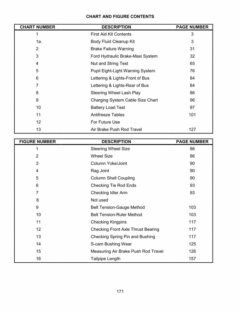
CHART AND FIGURE CONTENTS
CHART NUMBER DESCRIPTION PAGE NUMBER 1
1a.
2
3
4
5
6
7
8
9
10
11
12
13
First Aid Kit Contents
Body Fluid Cleanup Kit
Brake Failure Warning
Ford Hydraulic Brake-Maxi System
Nut and String Test
Pupil Eight-Light Warning System
Lettering & Lights-Front of Bus
Lettering & Lights-Rear of Bus
Steering Wheel Lash Play
Charging System Cable Size Chart
Battery Load Test
Antifreeze Tables
For Future Use
Air Brake Push Rod Travel
3
3
31
32
65
76
84
84
86
96
97
101
127
FIGURE NUMBER DESCRIPTION PAGE NUMBER 1
2
3
4
5
6
7
8
9
10
11
12
13
14
15
16
Steering Wheel Size
Wheel Size
Column Yoke/Joint
Rag Joint
Column Shell Coupling
Checking Tie Rod Ends
Checking Idler Arm
Not used
Belt Tension-Gauge Method
Belt Tension-Ruler Method
Checking Kingpins
Checking Front Axle Thrust Bearing
Checking Spring Pin and Bushing
S-cam Bushing Wear
Measuring Air Brake Push Rod Travel
Tailpipe Length
86
86
90
90
90
93
93
103
103
117
117
117
125
126
157
171

STATUTORY REQUIREMENT FOR SAFE TRANSPORTATION OF STUDENTS
1006.22 Safety and health of students being transported - Maximum regard for safety and adequate protection of health are primary requirements that must be observed by school boards in routing buses, appointing drivers, providing and operating equipment, in accordance with all requirements of law and rules of the State Board of Education in providing transportation pursuant to s. 1006.21:
(10) Each district school board shall designate and adopt a specific plan for adequate examination, maintenance and repair of transportation equipment. Examination of the mechanical and safety condition of each school bus must be made as required pursuant to rule of the State Board of Education. The State Board of Education shall base the rule on student safety considerations.
(11) The district school superintendent shall notify the district school board of any school bus that does not meet all requirements of law and rule of the State Board of Education and the district school board shall, if such school bus is in an unsafe condition, withdraw it from use as a school bus until the bus meets the requirements. The department may inspect or have inspected any school bus to determine whether the bus meets requirements of law and rules of the State Board of Education. The department may, after due notice to a district school board that any school bus does not meet certain requirements of law and rules of the State Board of Education, rule that the bus must be withdrawn from use as a school bus, this ruling to be effective immediately or upon a date specified in the ruling, whereupon the district school board shall withdraw same from use as a school bus until it meets requirements of law and rules of the State Board of Education and until the department has officially revoked the pertinent ruling. Notwithstanding any other provisions of this chapter, general-purpose urban transit systems are declared qualified to transport children to and from school.
STATE BOARD OF EDUCATION RULE ON SCHOOL DISTRICT RESPONSIBILITIES FOR THE SAFE TRANSPORTATION OF STUDENTS
6A-3.0171 Responsibilities of School Districts for Student Transportation. Each school board shall exercise specific powers and responsibilities, as follows: (8) Inspection and maintenance of school buses: (a) To provide, after considering recommendations of the superintendent, adequate storage, maintenance and inspection procedures for all buses owned by the school board and to assure that all contract buses in use in the district are properly inspected and maintained in accordance with law and rules of the State Board of Education. (b) The inspection shall be conducted in accordance with procedures and include all items listed in the State of Florida School Bus Safety Inspection Manual, 2017 Edition and documented on the Florida School Bus Safety Inspection Form (2017-IF) effective March 2017. The manual and form 2017-IF are hereby incorporated by reference and made a part of this rule. These documents may be obtained from the Department’s website at: http://fldoe.org/core/fileparse.php/7585/urlt/0085485-floridaschoolbussafetyinspectionmanual-1.pdf and may also be obtained from the School Transportation Management Section, Department of Education, 325 West Gaines Street, Tallahassee, Florida 32399, at a cost not to exceed actual production and distribution cost. (c) Inspection of buses shall be scheduled and performed at a maximum interval of thirty school days. Any bus removed from service to disrupt the safety inspection schedule shall be inspected prior to being returned to service. All deficiencies discovered during the safety inspection shall be noted on the inspection form. Follow-up repairs of all safety related items shall be made before the bus is returned to service and shall be documented. (d) School bus inspections shall be conducted by technicians certified as school bus safety inspectors in accordance with the State of Florida School Bus Safety Inspection Manual, 2017 Edition. The requirement that inspections be performed by a certified Florida School Bus Safety Inspector may be waived for a period not to exceed six (6) months when an emergency condition exists, upon written notification to the Commissioner of Education by the district superintendent. (e) No person shall knowingly render inoperative or reduce compliance of any school bus equipment required to meet Federal Motor Vehicle Safety Standards applicable at the time of manufacture.
172

FLORIDA SCHOOL BUS SAFETY INSPECTION FORM
Status Code
Item OK Bus # Mileage RO # Date X = Needs Repair
(or as noted) Chassis/Body Capacity Model Year O = Out of Service
N/A Not Applicable Shop Location
District School Board
FLORIDA SCHOOL BUS SAFETY INSPECTION FORM
_____________________________________________________________District School Board___
Bus#______________Mileage________________RO#_________________Date________________
Chassis/Body_____________________________ Capacity______________Model Year__________
Shop Location_____________________________________________________________________
Status Code INSPECTION ITEMS COMMENTS
(Note Specific Deficiencies) Tech.
Initials A. INSIDE BUS
1. Emergency Equipment - Fire Ext. (pressure/tag/mount), First Aid Kit, Body Fluid Cleanup Kit and Reflectors
2. Registration and Insurance Card 3. Neutral Safety Switch, Shifter and Noise Abatement Switch 4. Engine Controls - Key Switch, Accelerator and Engine Shutdown 5. Gauges, Indicators, Dash and Switch Panel Lights, Engine Warning
Lights/ Buzzers and ABS Warning Light 6. Air Brake System - Gauge(s), Build-Up, Governor, Park Brake,
Adjustment, Air Leaks, Low Air Warning, PP-1 Pop-Off and Pedal 7. Hydraulic Brakes - Warning Light, Gauge, Pedal Travel and
Fade, Power Assist and Park Brake 8. Windshield Wipers and Washers - Operation, Park and Blades
9. Heaters, Defrosters, Auxiliary Dash or Header Fan(s) 10. Dome and Step Well Lights 11. Service Door - Operation, Control and Overhead Pad 12. Horns 13. Mirror Adjustment and Condition - Rear vision, Cross-view, Side-view and Interior 14. Driver’s Seat and Seat Belt 15. Passenger Seats - Frames, Mounting, Pads, Cuts, Bottoms, Modesty
Panels, Stanchions, Passenger Securement Devices and Webbing Cutter 16. Emergency Doors, Windows, Hatches and Passenger Check System
Operation, Buzzers, Labeling and Overhead Pad 17. Windshield, Side and Rear Windows - Cracks, Fogging, Latches and Visor 18. Wheelchair Lift, Door and Securement System - (if equipped) 19. Two-Way Radio Operation - (if equipped) 20. Interior Wiring, Cab Hoses and Fire Wall Seals 21. General Condition of Bus Interior - Floor, Step well, Grab Rail(s),
Paneling, Broom Mounting, Loose Objects Secured and Engine Cover B. OUTSIDE BUS
1. Headlights, Turn Signals, Hazard, Brake, Tail, Backup Lights, Backup Alarm and Park Lights
2. Clearance, Side Marker, ID Lights, Reflectors and Strobe Light 3. Pupil Warning Lights
4. Stop Arm(s) and Student Crossing Arm - Wiring, Air or Vacuum Leak and Decal 5. General Condition of Bus Exterior - Mirrors, Bumpers, Body Damage, Paint
Reflective Marking, Lettering, Emergency Door, Engine Hood and Cleanliness C. ENGINE COMPARTMENT
1. Steering - Play, Column, Steering Gear Box Mounting, Pitman Arm, Drag Link, Steering Arm, Tie Rod & Ends and Idler Arm
2. Batteries - Hold Down, Terminals, Cables, Cleanliness, Slide Tray and Load Test 3. Fluid Levels and Condition - Brake, Power Steering,
Oil, Transmission, Windshield Washer, Coolant (Antifreeze __________°F) and DEF 4. Belts and All Hoses - Tightness, Condition, Routing and Belt Alignment 5. Accessory Mounting and Condition – Power Steering Pump,
Air Compressor and Filter, Water Pump, Fan, Alternator and Air Cleaner (Restriction) ________________(H2O)
6. Wiring - Routing and Condition
173
Form 2017-IF (effective March 2017)

Status Code INSPECTION ITEMS COMMENTS
(Note Specific Deficiencies) Tech. Initials
7. Fuel System and Lines
8. Radiator - Mounting, Cap, Reservoir and Fan Shroud
D. UNDERNEATH BUS 1. Front Suspension - I-Beam, U-Bolts, Springs, Spring Mounts, Shackles, Pins and
Bushings, Shocks, Kingpins, Wheel Bearings, Seals, A-Frames, Bushings and Ball Joints
2. Front Brakes - Hoses, Lines, Chambers, Slack Adjusters, Push rods, Linings, Drums, Rotors and Wheel Cylinders or Calipers. Check and Adjust MSA-Equipped Brakes. Do Not Adjust ASA-Equipped Brakes
3. Engine Mounts, Transmission Mounts and Starter Mounting
4. Transmission - Bolts, Linkage, Lines, Filter and Cooler
5. Fluid Leaks - Oil, Coolant, Transmission, Power Steering and DEF
6. Fuel and DEF Tank - Leaks, Mounting, Hoses and Wiring
7. Brake Equipment – ABS, Lines, Valves, Reservoir Mounting and Bleed Reservoirs
8. Driveline - Shafts, U-Joints, Yokes, Hanger Bearings, Guards Driveshaft and Park brake 9. Rear Suspension - Axle Housing, Vent, Differential, Springs, U-Bolts, Shocks, Spring
Shackles, Pins and Bushings, Hangers, Seals and Wheel Bearings 10.Rear Brakes - Hoses, Lines, Chambers, Slack Adjusters, Push rods, Linings, Drums,
Rotors and Wheel Cylinders or Calipers. Check and Adjust MSA-Equipped Brakes. Do Not Adjust ASA-Equipped Brakes
11.Body Securement and Structure - Hold Downs, Floor, Outriggers, Braces, Skirts and Chassis Frame Rails
12.Exhaust System - Leaks, Mounting, Muffler, Tailpipe and DEF System 13.Wheels and Tires - Tread Depth, Pressure, Damage, Matching, Alignment
and Wheel Hardware E. LUBRICATION & MAINTENANCE (OPTIONAL)
1. Change Oil and Replace Oil Filter(s) Qts. _______________
2. Replace Fuel Filter(s) Primary/Secondary and Drain Separator
3. Replace Transmission Filter(s) Qts. _______________
4. Replace Air Compressor Filter (if applicable)
5. Replace Power Steering Filter Pts. ______________
6. Replace Engine Air Cleaner Filter
7. Replace Coolant Filter (if applicable)
8. Test Starting and Charging System Amps _________ Volts __________
9. Lubricate Chassis and Body Lbs. ______________ 10.Air Conditioning If equipped, perform A/C system preventive maintenance
according to manufacturer recommendations and district procedure. F. ROAD TEST
1. Brake Performance - Park Brake, Stopping Distance and Equalization 2. Engine, Transmission and Driveline - Engine Performance, Governor and Shifting 3. Steering and Handling - Free Play, Power Assist, Column and Tracking
174
Form 2017-IF (effective March 2017)

FLORIDA SCHOOL BUS SAFETY INSPECTION FORM
Status Code
Item OK Bus # Mileage RO # Date X = Needs Repair
(or as noted) Chassis/Body Capacity Model Year O = Out of Service
N/A Not Applicable Shop Location
District School Board
FLORIDA SCHOOL BUS SAFETY INSPECTION FORM
__________________________________Sunshine___________________District School Board___
Bus#_04-1234______Mileage__96,000________RO#____Y43219-R_____Date______8/20/2015__
Chassis/Body____IC/Thomas/BB_____________ Capacity_______77_____Model Year___2004___
Shop Location__________Busville__________________________________________________ _
Status Code INSPECTION ITEMS COMMENTS
(Note Specific Deficiencies) Tech. Initials
A. INSIDE BUS
1. Emergency Equipment - Fire Ext. (pressure/tag/mount), First Aid Kit,
Body Fluid Cleanup Kit and Reflectors 2. Registration and Insurance Card 3. Neutral Safety Switch, Shifter and Noise Abatement Switch 4. Engine Controls - Key Switch, Accelerator and Engine Shutdown
5. Gauges, Indicators & Dash and Switch Panel Lights, Engine Warning
Lights/ Buzzers and ABS Warning Light
6. Air Brake System - Gauge(s), Build-Up, Governor, Park Brake,
Adjustment, Air Leaks, Low Air Warning, PP-1 Pop-Off and Pedal
N/A 7. Hydraulic Brakes - Warning Light, Gauge, Pedal, Travel & Fade, Power Assist and Park Brake
8. Windshield Wipers & Washers - Operation, Park and Blades
9. Heaters, Defrosters, Auxiliary Dash or Header Fan(s) 10. Dome and Step Well Lights 11. Service Door - Operation, Control and Overhead Pad 12. Horn(s) 13. Mirror Adjustment and Condition - Rear vision, Cross/Side-View and Interior
14. Driver’s Seat and Seat Belt
15. Passenger Seats - Frames, Mounting, Pads, Cuts, Bottoms, Modesty
Panels, Stanchions, Passenger Securement Devices and Webbing Cutter
16. Emergency Doors, Windows, Hatches and Passenger Check System –
Operation, Buzzers, Labeling and Overhead Pad 17. Windshield, Side and Rear Windows -Cracks, Fogging, Latches and Visor
N/A 18. Wheelchair Lift, Door and Securement System - (if equipped)
N/A 19. Two-Way Radio Operation - (if equipped)
20. Interior Wiring, Cab Hoses and Fire Wall Seals
21. General Condition of Bus Interior - (Including floor, step well, grab rail(s),
paneling, trim, broom mounting, loose objects secured and engine cover B. OUTSIDE BUS 1. Headlights, Turn Signals, Hazard, Brake, Tail, Backup
Lights, Backup Alarm and Park Lights X 2. Clearance, Side Markers, ID Lights, Reflectors and Strobe Light LF Corner Not Working RM
3. Pupil Warning Lights - (see eight light warning system chart)
4. Stop Arm(s) and Student Crossing Arm - Wiring, Air or Vacuum Leak and Decal
5. General Condition of Bus Exterior - Mirrors, Bumpers, Body Damage, Paint,
Reflective Marking, Lettering, Emergency Door, Engine Hood and Cleanliness C. ENGINE COMPARTMENT
1. Steering - Play, Column, Steering Gear Box Mounting, Pitman Arm,
Drag Link, Steering Arm, Tie Rod & Ends and Idler Arm
2. Batteries - Hold Down, Terminals, Cables, Cleanliness, Slide Tray and Load
Test 3. Fluid Levels and Condition - Brake, Power Steering,
Oil, Transmission, Windshield Washer, Coolant (Antifreeze ___________°F) and DEF
X/O 4. Belts and All Hoses - Tightness, Condition, Routing and Belt Alignment. X - Main Drive Belt Glazed O- A/C Belt Twisted in Pulleys
5. Accessory Mounting and Condition - P.S. Pump, Air Compressor
and Filter, Water Pump, Fan, Alternator and Air Cleaner (Restriction)__________(H2O) 6. Wiring - Routing and Condition.
175
Form 2017-IF (effective March 2017)

Status Code INSPECTION ITEMS COMMENTS
(Note Specific Deficiencies) Tech
Initials
7. Fuel System and Lines
8. Radiator - Mounting, Cap, Reservoir and Fan Shroud.
D. UNDERNEATH BUS
1. Front Suspension - I-Beam, U-Bolts, Springs, Spring Mounts, Shackles, Pins &
Bushings, Shocks, Kingpins, Wheel Bearings, Seals, A-Frames, Bushings; Ball Joints
O 2. Front Brakes - Hoses, Lines, Chambers, Slack Adjusters, Push rods, Linings,
Drums, Rotors, Wheel Cylinders or Calipers, Check and Adjust MSA Equipped Brakes. Do Not Adjust ASA Equipped Brakes
Less than ¼ inch (Q-Plus)
3. Engine Mounts, Transmission Mounts and Starter Mounting
4. Transmission - Bolts, Linkage, Lines, Filter and Cooler
5. Fluid Leaks - Oil, Coolant, Transmission, P.S., DEF, etc.
6. Fuel and DEF Tank - Leaks, Mounting, Hoses and Wiring
X 7. Brake Equipment - ABS, Lines, Valves, Reservoir Mounting and Bleed Reservoirs Bleed Tanks RM
8. Driveline - Shafts, U-Joints, Yokes, Hanger Bearings, Guards and Driveshaft Park
Brake
9. Rear Suspension - Axle Housing, Vent, Differential, Springs, U-Bolts, Shocks,
Spring Shackles, Pins and Bushings, Hangers, Wheel Bearings and Seals
10. Rear Brakes - Hoses, Lines, Chambers, Slack Adjusters, Push rods, Linings, Drums, Rotors and Wheel Cylinders or Calipers - Check and Adjust MSA Equipped Brakes - Do Not Adjust ASA Equipped Brakes
11. Body Securement and Structure - Hold Downs, Floor, Outriggers, Braces,
Skirts and Chassis Frame Rails
12. Exhaust System - Leaks, Mounting, Muffler, Tailpipe and DEF System
O 13. Wheels and Tires - Tread Depth, Pressure, Damage, Matching, Alignment and Wheel Hardware
RF 1/32 inch, and Low Air Pressure
E. LUBRICATION & MAINTENANCE (OPTIONAL) X 1. Change Oil and Replace Oil Filter(s) Qts. ____28_________ RM
X 2. Replace Fuel Filter(s) Primary/Secondary and Drain Separator RM
N/A 3. Replace Transmission Filter(s) Qts. _______________
N/A 4. Replace Air Compressor Filter (if applicable)
N/A 5. Replace Power Steering Filter Pts. ______________
N/A 6. Replace Engine Air Cleaner Filter
N/A 7. Replace Coolant Filter (if applicable)
X 8. Test Starting and Charging System Amps 105_____Volts 15.2 RM
X 9. Lubricate Chassis and Body Lbs. ____1/2_______ RM
X 10. Air Conditioning - Perform A/C System Preventive Maintenance (if equipped) according to district procedure RM
F. ROAD TEST
1. Brake Performance - Park Brake, Stopping Distance and Equalization
2. Engine, Transmission and Driveline - Engine Performance, Governor and Shifting
3. Steering and Handling - Free Play, Power Assist, Column and Tracking
176
Form 2017-IF (effective March 2017)

Repair Order
Vehicle Number Mileage Description of Vehicle Repair Order # Make Year Reg. Lift A/C
Date: Organization Name:
________________________ School District
Safety Inspection Yes ( ) No ( )
Route/Driver: Inspected By:
Repairs Needed: Out-of-service Date:
In Service Date:
Quantity Parts Est. Cost Tech. Init.
Repairs Time Hrs. 1/10
Cost Subtotal Total Man-Hours Quantity Tires and Batteries Filters Mileage Yes No Tune/Up-Front/Wheels-Oil Mileage Yes No
Fuel/Oil Tune-Up Air Frt Wheels Coolant Oil Change Trans
Total
177
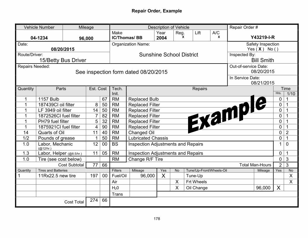
Repair Order, Example
Vehicle Number Mileage Description of Vehicle Repair Order #
Y43219-I-R04-1234 96,000 Make IC/Thomas/ BB
Year 2004
Reg. X
Lift A/C X
Date: 08/20/2015
Organization Name:
Sunshine School District
Safety Inspection Yes ( X ) No ( )
Route/Driver: 15/Betty Bus Driver
Inspected By: Bill Smith
Repairs Needed: See inspection form dated 08/20/2015
Out-of-service Date: 08/20/2015
In Service Date: 08/21/2015
Quantity Parts Est. Cost Tech. Init.
Repairs Time Hrs. 1/10
1 1157 Bulb 67 RM Replaced Bulb 0 1 1 187439CI oil filter 8 50 RM Replaced Filter 0 1 1 LF 3949 oil filter 14 50 RM Replaced Filter 0 1 1 1872526CI fuel filter 7 82 RM Replaced Filter 0 1 1 PH79 fuel filter 5 32 RM Replaced Filter 0 1 1 1875921CI fuel filter 4 90 RM Replaced Filter 0 1 14 Quarts of Oil 11 40 RM Changed Oil 0 2 1/2 Pounds of grease 1 50 RM Lubricated Chassis 0 1 1.0 Labor, Mechanic
(@12/hr.) 12 00 BS Inspection Adjustments and Repairs 1 0
1.3 Labor, Helper (@8.5/hr.) 11 05 RM Inspection Adjustments and Repairs 0 1 1.0 Tire (see cost below) RM Change R/F Tire 0 3
Cost Subtotal 77 66 Total Man-Hours 2 3 Quantity Tires and Batteries Filters Mileage Yes No Tune/Up-Front/Wheels-Oil Mileage Yes No 1 11Rx22.5 new tire 197 00 Fuel/Oil 96,000 X Tune-Up X
Air X Frt Wheels X H20 X Oil Change 96,000 X Trans
Cost Total 274 66
178

School Bus Safety Inspection Certification Program
This program shall meet the requirements of rule 6A-3.0171, F.A.C. Technicians performing school bus inspections shall certify as School Bus Safety Inspectors. The certification shall be in effect until the end of the fifth fiscal year (June 30) from the certification date stated on the certificate. For example, a certificate issued on June 29, 2017, is valid through June 30, 2022. Certifications renewed during the fifth fiscal year, shall be in effect for an additional five fiscal years. The qualifications, training and testing requirements for certification are as follows:
A. Level 1 Certified School Bus Safety Inspector
1) Qualifications Requirements: a) Candidates must document at least two years of journeyman-level mechanical
experience in the repair and maintenance of motor vehicles in the areas of automotive, truck, heavy equipment or bus or successful course completion in vehicle maintenance and repair from an accredited school with a minimum two-year curriculum. The required mechanical experience is defined as “hands-on” or “wrench-turning” experience.
b) Candidates must submit a State of Florida, School Bus Safety Inspector Application (form 2017-SI) to the inspector-trainer for the two-day class; to the district test administrator prior to the online test; and to the FDOE test administrator prior to the hands-on test.
c) Candidates’ current employers shall classify them as journeyman-level mechanics/technicians. This classification must be in the form of an official job description. In cases where candidates are working as journeyman-level mechanics/technicians without the proper classification, they may have their employer submit a letter to the School Transportation Management Section (STMS) of the FDOE requesting a waiver of the job description requirement. Acceptable job descriptions cannot contain language indicating candidate’s primary responsibility is to perform mechanic’s assistant or equivalent duties.
2) Training Requirements: a) School bus safety inspector candidates shall attend a minimum two-day training
program conducted by a certified school bus safety inspector-trainer. b) Candidates should be thoroughly familiar with the current edition of the State of Florida
School Bus Safety Inspection Manual prior to attending a training class. c) Candidates shall train/practice performing school bus inspections on several school
buses prior to hands-on testing, using the procedures and information learned in the training class.
3) Testing Requirements: a) Testing consists of two parts, a 100-question online knowledge test and a hands-on
application test. b) FDOE-approved test administrators will conduct online testing. c) The STMS will administer the hands-on testing in the field. d) Candidates shall pass both tests to certify as a State of Florida School Bus Safety
Inspector.
179

4) Written (online) Test: a) All written test questions correspond to material in the inspection manual. b) Candidates have 90 minutes to take the test. c) The minimum passing score is 80 percent. d) This test is an open-book test. Candidates may use the State of Florida School Bus
Safety Inspection Manual during the 100-question online test. e) Prior to hands-on testing, a candidate should pass the online test.
5) Hands-on Test: a) The FDOE will provide the time, date and location of each regionally scheduled hands-
on testing class to school district transportation departments. b) Candidates will be required to perform actual physical inspections of school buses and
should dress accordingly. All needed equipment will be provided at the test site. c) Candidates must bring a current State of Florida School Bus Safety Inspection Manual
and a valid driver’s license to the test site. d) Candidates should use the information learned in their training class, the inspection
manual and their professional knowledge while taking the hands-on inspection test. e) Candidates have 90 minutes to take the test. f) The test bus will have a minimum of nine specific and pre-determined deficiencies that
the candidate must identify and properly describe on the inspection form. The specific deficiencies may be either existing or ones created by the test administrator.
g) Each of the nine deficiencies counts as 10 points. h) A properly completed inspection form counts as 10 points. The candidate can make a
maximum of three mistakes on the form. Examples of some common mistakes are: 1) Odometer reading not recorded 2) A blank in the Status Code column. 3) Failure to clearly identify or describe any of the nine specific deficiencies
i) The minimum passing score is 90 percent. j) The employer listed on the State of Florida School Bus Safety Inspector Application
(form 2017-SI) will receive certification status of each candidate.
180

B. Level 2 Certified School Bus Safety Inspector/Trainer
1) Qualifications Requirements All the requirements listed in Section A. Level 1. Certified School Safety Bus Inspector, plus the following additional items: a) Candidates should be thoroughly knowledgeable of the contents of the current edition
of the State of Florida School Bus Safety Inspection Manual. b) Candidates must possess skills and abilities required to present school bus inspection
training material in a manner that facilitates learning and must exhibit leadership qualities and above-average professionalism in the performance of their duties.
c) Candidates must submit a copy of their completed State of Florida School Bus Safety Inspector Application (form 2017-SI) to the FDOE trainer at the time of the train-the-trainer class.
2) Training Requirements a) Trainer candidates must attend a two-day, FDOE-sponsored train-the-trainer class,
testing session and periodic update training sessions. b) Candidates will receive intense training and detailed inspection program information
from the FDOE trainer in the following specific areas: 1) Training techniques 2) Purpose of the program and applicable laws and State Board of Education rules 3) How to use the inspection manual and the inspection form 4) Recertification program 5) Inspection, repair-or-note, and out-of-service criteria
3) Testing Requirements a) See “Section A.” Trainers must meet the same testing requirements as an inspector. b) Additional testing requirements include performance-based scoring at the two-day
train-the-trainer class in which trainer candidates will be required to conduct simulated training classes.
c) The FDOE will schedule periodic train-the-trainer update classes. Trainers are strongly encouraged to attend.
4) Duties a) Trainers must ensure that inspector-testing candidates meet all requirements. b) Trainers must sign the State of Florida School Bus Safety Inspector Application (form
2017-SI) to verify that inspector candidates have received appropriate training. c) Trainers will occasionally conduct inspection training for school districts, charter
schools and private transportation providers that do not otherwise have trainers available to them.
181

C. Level 3 Supervisor
The Supervisor 1 classification has the same requirements as the Level 1 Certified School Bus Safety Inspector. This classification is for a supervisor who manages the school bus inspection process and may perform inspections.
Inspector Classification Requirements
Classification Levels
Min. 2 years Technical
Experience
Classified as Journeyman
Written Test Passed
Hands-on Test
Passed
Update Course
Attended 1. Inspector X X (1) X (3) X (5)
2. Trainer X X (1) X (3), (4) X (5)
3. Supervisor X X (2) X (3) X (5)
1) Requirements specified in Section A.
2) Supervisors with two years of journeyman-level experience are not required to have job descriptions containing mechanic and/or technician classification language.
3) 100-question online test.
4) There is no written test for trainer candidates. Trainer candidates will receive a score during the two-day train-the-trainer class.
5) 30-question online recertification test.
Note: A trainer must provide the candidate with inspection manual revision information and sign the State of Florida School Bus Safety Inspector Application (form 2017-SI) prior to testing.
182

School Bus Safety Inspection Recertification Program
School bus safety inspectors, inspector-trainers and supervisor-inspectors must recertify during the fifth fiscal year of certification. Following are the qualifications, eligibility and testing requirements for recertification:
1. Qualifications Requirements: a) Recertification must take place between July 1 and June 30 of the fifth full fiscal year
following the date of original certification or subsequent recertification. For example, if an inspector certified in January 2014, he/she would need to recertify anytime between July 1, 2018, and June 30, 2019. If an inspector certified in August 2014, recertification would be required before June 30, 2020. Note: Recertification candidates are encouraged to begin recertification study and testing early in the fiscal year during which recertification is required.
b) Inspector-trainers must ensure that recertification candidates obtain manual revision information and that candidates have thoroughly studied this information prior to testing. Trainers must sign the State of Florida School Bus Safety Inspector Application (form 2017-SI) to file with the school district transportation department.
2. Eligibility Requirements: Inspectors who fail to recertify by the expiration date on their certificate must not inspect buses until recertified (see items (g) and (h) below).
3. Testing Requirements: a) Testing consists of a 30-question online test. b) The test consists of questions based on revised and non-revised inspection criteria from
the Florida School Bus Safety Inspection Manual. c) District test administrators will conduct online testing. d) This test is an open-book test. Candidates may use the State of Florida School Bus Safety
Inspection Manual during the 30-question online test. e) The candidate must provide the test administrator with a valid driver license and a
completed State of Florida School Bus Safety Inspector Application (form 2017-SI) with an email address, if available.
f) Recertification candidates will have 30 minutes to take the test. g) Recertification candidates can take the test as many times as necessary to achieve a
passing score. h) If an inspector fails to recertify before his/her current certification expires, he/she MUST
NOT inspect buses. If an inspector fails to recertify prior to the expiration date of his/her last certification, he/she will be required to take the 100-question online test and pass a hands-on test to recertify.
i) The minimum passing score for the online recertification test is 80 percent. j) The online test program will provide the candidate with a score immediately. The current
employer listed on the State of Florida School Bus Safety Inspector Application (form 2017-SI) will receive the certificate by mail.
183

(This page intentionally left blank)
184
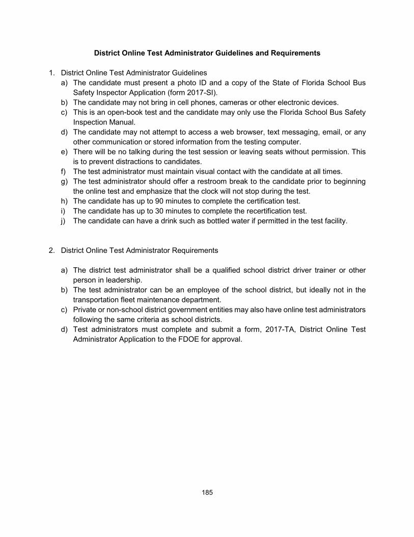
District Online Test Administrator Guidelines and Requirements
1. District Online Test Administrator Guidelines a) The candidate must present a photo ID and a copy of the State of Florida School Bus
Safety Inspector Application (form 2017-SI). b) The candidate may not bring in cell phones, cameras or other electronic devices. c) This is an open-book test and the candidate may only use the Florida School Bus Safety
Inspection Manual. d) The candidate may not attempt to access a web browser, text messaging, email, or any
other communication or stored information from the testing computer. e) There will be no talking during the test session or leaving seats without permission. This
is to prevent distractions to candidates. f) The test administrator must maintain visual contact with the candidate at all times. g) The test administrator should offer a restroom break to the candidate prior to beginning
the online test and emphasize that the clock will not stop during the test. h) The candidate has up to 90 minutes to complete the certification test. i) The candidate has up to 30 minutes to complete the recertification test. j) The candidate can have a drink such as bottled water if permitted in the test facility.
2. District Online Test Administrator Requirements
a) The district test administrator shall be a qualified school district driver trainer or other person in leadership.
b) The test administrator can be an employee of the school district, but ideally not in the transportation fleet maintenance department.
c) Private or non-school district government entities may also have online test administrators following the same criteria as school districts.
d) Test administrators must complete and submit a form, 2017-TA, District Online Test Administrator Application to the FDOE for approval.
185

DISTRICT ONLINE TEST ADMINISTRATOR APPLICATION
To submit a request for qualification, this application must be completed by the school district or organization. Under
provisions of rule 6A-3.0171, Florida Administrative Code (F.A.C.), successful applicants will be qualified to administer the
State of Florida School Bus Safety Inspector online test. Test administrators will be in direct contact with Florida Department
of Education (FDOE) to coordinate all certification testing for the school district or organization. Test administrators may
assist other school districts or organizations that do not have a test administrator. Applicants must submit this application
to the FDOE, School Transportation Management Section. The superintendent of schools or an executive manager for any
other type of organization must sign this application.
PLEASE PRINT OR TYPE
Employer: ________________________________________________________________________________________
Name: _______________________________________________________________Date:________________________
Job Title: _________________________________________________________________________________________
Address: _________________________________________________________________________________________
Telephone Number: ___________________________Other Telephone Number: ________________________________
Email address: ____________________________________________________________________________________
Applicant’s Signature: ___________________________________________________Date:_______________________
I certify that the person listed above meets the requirements to be a School Bus Safety Inspector Test Administrator for
_______________________________________________________________________ (organization or school district).
I agree to work cooperatively to provide testing opportunities requested by other organizations or school districts that do not
have a test administrator or to fulfill testing requests made by the School Transportation Management Section of the FDOE.
Superintendent or Authorized Signature: _________________________________Date:__________________
Please send completed application to:
Florida Department of Education
School Transportation Management Section
325 West Gaines Street, Room 834
Tallahassee, Florida 32399-0400
850-245-9935 FAX
850-245-9795 Phone
186 Form 2017-TA Effective March 2017

_________________________________________________________________________________________________________________________
________________________________________________________________________________________
_________________________________________________________________________________________________________________________
____________________________________________________________________
________________________________________________________________________________________
________________________________________________________________________________________
_____________________________________________________________________________
________________________________________________________________________________________
STATE OF FLORIDA, SCHOOL BUS SAFETY INSPECTOR APPLICATION (Please Type or Print)
First Name M.I. Last Name
Email Address
Home Street Address, Apt. # City State Zip ____________________ ____ / ____ / ____ Education: (Check Highest Level achieved) Driver License Number (Last 6 Digits) Birth Date __ High School or GED __ Two-year College
__________________________________________________________ __ Post graduate __ Four-year College The School District or Employer You Work For
___ (CERTIFICATION) ___ (RECERTIFICATION): CHECK ONE
APPLICATION LEVEL - CHECK ONE:
___ 1. INSPECTOR ___ 2. TRAINER ___ 3. SUPERVISOR
WORK EXPERIENCE For certification levels, 1, 2 and 3, the applicant must be able to document a minimum of two years journeyman-level mechanical experience or a two-
year Vocational/Technical (Vo-Tech) degree in any of the following areas: a) Automotive; b) Truck; c) Heavy Equipment or, d) Buses (transit or school).
List employers where you gained applicable experience:
1. Employer (Current or most recent):
Street Address City State Zip
Your Position or Job Title: ___________________________________________________________________
Supervisor’s Name: _________________________________ Title: __________________________________
Tel. #: (______) _____ - ________ Employed From: _____/_____/_____ To: ____/_____/______
2. Employer (Previous):
Street Address City State Zip
Your Position or Job Title: ___________________________________________________________________
Supervisor’s Name: _________________________________ Title: __________________________________
Tel. #: (______) _____ - ________ Employed From: _____/_____/_____ To: ____/_____/_____
Note: If needed to demonstrate compliance with requirements, list additional employers, mechanical experience or degree information on a separate piece of paper and attach it to this application.
187 Form 2017-SI Effective March 2017

_____________________________________________________________________________
CERTIFICATION INFORMATION
Name of Employer or School District
________________________________________________________, Florida _______________ Work or Mailing Address City Zip
Supervisor’s Name: _____________________________ Title: ___________________________
Note: Send the completed application to Florida Department of Education, School Transportation Management Section at 325 West Gaines Street, suite 834, Tallahassee, Florida 32399-0400. All signatures are required and the test candidate must bring a valid driver’s license to the hands-on test site.
Applicant’s Signature: ______________________________________________ Date: ____/____/______
The applicant meets all training requirements:
Trainer’s Signature: _________________________ Trainer’s Cert. # ______________ Date: ____/____/____
The applicant meets all applicable qualifications and requirements:
Transportation Director’s Signature: ___________________________________ Date:______/______/______
THIS SECTION FOR FDOE USE ONLY
Inspector: ________ Trainer: ________ Certification________ Recertification________
Applicant denied certification due to:
Insufficient Data ____ Does Not Qualify ____ Insufficient Experience _____ Classified Mechanic’s Helper ____ Training Not Received ____
Written (online) Test Date: ______/_____/______ Passed_________Failed________
* Retest Date: 1. ______/_____/______ Passed_________Failed________ * Retest Date: 2. ______/_____/______ Passed_________Failed________ * Retest Date: 3. ______/_____/______ Passed_________Failed________
Hands-On Test Date: ______/_____/______ Passed_________Failed________
* Retest Date: 1. ______/_____/______ Passed_________Failed________ * Retest Date: 2. ______/_____/______ Passed_________Failed________ * Retest Date: 3. ______/_____/______ Passed_________Failed________ * If Applicable
Certified By:_________________________________ Date______/______/_________ Name of FDOE Official
188 Form 2017-SI Effective March 2017
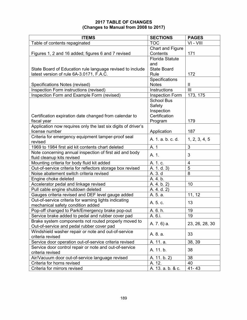
2017 TABLE OF CHANGES (Changes to Manual from 2008 to 2017)
ITEMS SECTIONS PAGES Table of contents repaginated TOC VI - VIII
Figures 1, 2 and 16 added; figures 6 and 7 revised Chart and Figure Contents 171
State Board of Education rule language revised to include latest version of rule 6A-3.0171, F.A.C.
Florida Statute and State Board Rule 172
Specifications Notes (revised) Specifications Notes II
Inspection Form instructions (revised) Instructions III Inspection Form and Example Form (revised) Inspection Form 173, 175
Certification expiration date changed from calendar to fiscal year
School Bus Safety Inspection Certification Program 179
Application now requires only the last six digits of driver’s license number Application 187 Criteria for emergency equipment tamper-proof seal revised A. 1. a. b. c. d. 1, 2, 3, 4, 5
1969 to 1984 first aid kit contents chart deleted A. 1 3 Note concerning annual inspection of first aid and body fluid cleanup kits revised A. 1. 3
Mounting criteria for body fluid kit added A. 1. c. 4 Out-of-service criteria for reflectors storage box revised A. 1. d. 3) 5 Noise abatement switch criteria revised A. 3. d 8 Engine choke deleted A. 4. b. Accelerator pedal and linkage revised A. 4. b. 2) 10 Pull cable engine shutdown deleted A. 4. d. 2) Gauges criteria revised and DEF level gauge added A. 5. a. 11, 12 Out-of-service criteria for warning lights indicating mechanical safety condition added A. 5. c. 13
Pop-off changed to Park/Emergency brake pop-out A. 6. h. 19 Service brake added to pedal and rubber cover pad A. 6.i. 19 Brake system components not routed properly moved to Out-of-service and pedal rubber cover pad A. 7. 6) a. 23, 26, 28, 30
Windshield washer repair or note and out-of-service criteria revised A. 8. a. 33
Service door operation out-of-service criteria revised A. 11. a. 38, 39 Service door control repair or note and out-of-service criteria revised A. 11. b. 38
Air/Vacuum door out-of-service language revised A. 11. b. 2) 38 Criteria for horns revised A. 12. 40 Criteria for mirrors revised A. 13. a. b. & c. 41- 43
189

ITEMS SECTIONS PAGES Criteria for driver’s seat and belt revised A. 14. 44 Out-of-service criteria for passenger seat mounting fasteners revised A. 15. b. 45
Criteria for seats revised and seat height diagram added A. 15. c. 46 Criteria for seat upholstery revised A. 15. e. 48 Webbing cutter check and out-of-service criteria revised A. 15. i. 49 Criteria for emergency door revised A. 16. a. 50 Criteria for emergency hatch labeling revised A. 16. c. 1) 51 Post-Trip Passenger Check criteria revised A. 16. d. 52 Criteria for glass cracks and fogging revised A. 17. a. & b. 53, 54 Window will not stay closed moved to out-of-service revised A. 17. c. 55
Inspection procedures revised A. 18. 1) 56- 58 Out-of-service criteria for radio added A. 19. 59 Criteria for interior wiring and hoses revised A. 20. 60 Criteria for step well revised A. 21. b. 61, 62 NHTSA references to hand rails deleted A. 21. c. Criteria for loose objects revised A. 21. f. 64 NHTSA nut and string test from National Standards (Chart 4) added 65
LED type lights criteria revised B. 1. 67 Side Marker lights moved from B. 1. To B. 2. B. 1. 73 Repair and out-of-service criteria for parking lights revised B. 1. h. 72 Repair and out-of-service criteria for B. 2. revised B. 2. 73, 74 Criteria for switch on pre-1985 buses deleted B. 2. a. Criteria for out-of-service dates changed to OEM or equivalent B. 3. 75
Loose components moved from repair to out-of-service B. 4. a. & b. 77, 78 Alternating pattern added to out-of-service B. 4. a. 77 Old dates deleted from out-of-service B. 4. a. 77 Criteria for mirror surfaces and fasteners revised B. 5. a. 79 Bumper/body seal repair moved to out-of-service B. 5. b. 79 Mirror and brightness of lights added to out-of-service B. 5. i. 82 Repair and out-of-service criteria revised C. 1. a. 85 Order of procedures and criteria revised C. 2. 94- 97 Box and door added to battery slide tray C. 2. a. 94 Fluid levels criteria revised C. 3. c., d. & f. 98- 100 Criteria for wrong dipstick moved to out-of-service C. 3. d. 99 Procedures and criteria revised C. 4. 102-104 Engine air cleaner loose components moved to out-of-service C. 5. a. 105
Water pump fasteners repair criteria deleted C. 5. d. Wiring procedures and out-of-service criteria revised C. 6. 107 Reservoir added to radiator procedure and criteria C. 8. a. 109 Radiator cap incorrect type moved to out-of-service C. 8. b. 109 Fan shroud repair moved to out-of-service C. 8. d. 109 Chart 12 proper wiring gauge usage deleted
190

ITEMS SECTIONS PAGES Locking pin repair deleted D. 1. c. Note about greasing added to procedures D. 1. f. 114 Repair criteria revised to include ride height and air spring assembly D. 1. k. 116
Brake lines routing out-of-service criteria added D. 2. b. 118 Figure 12 specification change from 0.03 inch to 0.06 inch 117 Disc brake pads procedure and criteria added D. 2. g. 121 Air wedge brakes deleted D. 2. j. Starter heat shield procedure and criteria deleted D. 3. b. Leakage out-of-service criteria revised D. 5. a. 131 Leakage criteria revised D. 5. c. 132 DEF procedure and criteria added to fuel tank D. 6. 133, 134 Wiring repair moved to out-of-service D. 6. d. 134 Anti-lock brake systems repair criteria deleted D. 7. e. Drive-shaft foreign matter deleted D. 8. a. Guards out-of-service criteria revised D. 8. e. 138 Differential leaking moved to out-of-service D. 9. c. 140 Slack adjuster repair deleted, and out-of-service criteria revised D. 10. d. 146
Air wedge brake deleted D. 10. j. Frame rail padding missing repair deleted D. 11. a. Luggage compartment door latch repair moved to out-of-service D. 11. e. 155
Mud flap procedure and criteria added D. 11. 155 Exhaust leak and muffler repair items moved to out-of-service and DEF procedure and criteria added D. 12. 156
Warning light indicating a mechanical safety condition added to out-of-service F. 2. a. 167
Manual transmission deleted F. 2. b. 2) Supervisor II classification deleted Application for school bus safety inspector certification and application for school bus safety inspector recertification have been combined into one application
187
191

This page intentionally left blank
192