state of new mexico energy, minerals and natural...
TRANSCRIPT
State of New
Energy, Minerals and NaturalMexico
Resources Department
ivid R. Catanach, Division DirectorI Conservation Division
Susana MartinezGovernor
Ken McQueen Da'Cabinet Secretary O
Matthias SayerDeputy Cabinet Secretary
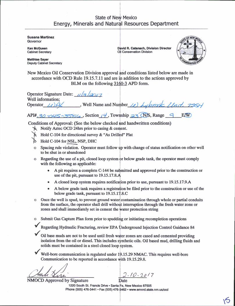
1New Mexico Oil Conservation Division approval and conditions listed below are made in accordance with OCD Rule 19.15.7.11 and are in addition to the actions approved by
BLM on the following 3160-3 APD form.
Operator Signature Date: .............. .Well information; jOperator ________, Well Name and Number //) jLyhrsrilr. //sid. 7^-C/V
API#, a, , Section / V, Township Range <=\ Effi)
Conditions of Approval: (See the below checked and handwritten conditions)^ Notify Aztec OCD 24hrs prior to casing & cement.
Njk, Hold C-104 for directional survey & “As Drilled” Plat
Hold C-104 for NSL^NSP, DHC
o Spacing rule violation. Operator must follow up with change of status notification on other well to be shut in or abandoned
o Regarding the use of a pit, closed loop system or below grade tank, the operator must comply with the following as applicable:
• A pit requires a complete C-144 be submitted and approved prior to the construction or use of the pit, pursuant to 19.15.17.8.A
• A closed loop system requires notification prior to use, pursuant to 19.15.17.9.A
• A below grade tank requires a registration be filed prior to the construction or use of the below grade tank, pursuant to 19.15.17.8.C
o Once the well is spud, to prevent ground water1 contamination through whole or partial conduits from the surface, the operator shall drill without interruption through the fresh water zone or zones and shall immediately set in cement the water protection string
I
o Submit Gas Capture Plan form prior to spuddiiig or initiating recompletion operations
Regarding Hydraulic Fracturing, review EPA Underground Injection Control Guidance 84
Oil base muds are not to be used until fresh water zones are cased and cemented providing isolation from the oil or diesel. This includes synthetic oils. Oil based mud, drilling fluids and solids must be contained in a steel closed loop bystem.
Well-bore communication is regulated under 19.15.29 NMAC. This requires well-bore Communication to be reported in accordance with 19.15.29.8.
DateNMOCD Approved by Signature1220 South St. Francis Drive • Santa Fe, New Mexico 87505
Phone (505) 476-3441 ■ Fax (505) 476-3462 • www.emnrd.state.nm.us/ocd

A1' r NOS:. f—
H ■ >iv* MP:._ -A-- /
rams 31® -3 BOWL 6^^.% pj ^(March 2012) CAMtKEj-'
UNITED STATES
DEPARTMENT OF THE INTERIOR
BUREAU OF LAND MANAGEMENT
APPLICATION FOR PERMIT TO DRILL OR REENTER
IOWOOOODG l to
BTSH=<3IO-
tOS.lt .VPPRtJVI-OOMB No. 1004-0137
Expires October 31,2014
5. Lease Serial No.
N0G14O31948
6. If Indian, Allotcc or Tribe Name
EASTERN NAVAJO
la. Type of work: 0DRJLL 0 RF ENTER
lb. Type of Well. [0Oil Well I Idas Well [ lother [ |Single Aonc 01 Multiple Zone
7 If Unil or CA Agreement, Name and No.
INITIAL. MANCOS PA / NMNM135216A
8. Lease Name and Well No.W LYBROOK UT 755H
2 Name of OpcralorWPX ENERGY LLC
9. API Well No.30-0^-as^!^
3a. Address 3b. Phone No. (include area code)
720 S Main Aztec NM 87410 (505)333-182210. Field and Pool, or Exploratory
LYBROOK MANCOS W / LYBROOK MA
4. Location of Well (Report location clearly and in accordance with any State requirement.*)At surfiU NESE /1867 FSL / 674 FEL / LAT 36.224787 / LONG -107.751536
At proposed prod. rotlP^ENE / 697 FNL / 330 FEL / LAT 36.203148 / LONG -107.732647
11. Sec., T. R, M. or Blk.and Survey or Area
SEC 14/T23N/R9W/NMP
I4. Distance in miles and direction from nearest (own or post office*
37.8 miles
12. County or Pansh 13. State
SAN JUAN NM
15. Distance from proposed*location to nearcsl 20 feetproperty or lease line, ft.(Also to nearest drig. unit line, if any)
16. No. of acres in lease
160
17. Spacing Unit dedicated to this well
440 ...OIL CONS. DIVDIST.18. Distance from proposed location*
(o nearest well, drilling, completed, 674 feet applied for, on this lease, fi.
19. Proposed Depth
4679 feet/14812 feet
20. BLM/B1A Bond Na on file
IND: B001576 J 1 201721. Elevations (Show whether DF, KDB, RT, GL, etc.)
6719 feet
22 Approximate date work will start*
12/01/2016
22 F,s!imated duration
30 days
3
24. AttachmentsThe following, completed in accordance with the requirements of Onshore Oil and Gas Order No. 1, must be attached to this form:
1. Well plat certified by a registered surveyor.
2 A Drilling Plan.
3. A Surface Use Plan (if the location is on National Forest System Lands, the SUPO must be filed with the appropriate Forest Service Office).
4. Bond to cover the operations unless covered by an existing bond on file (see Item 20 above).
5. Operator certification
6. Such other site specific information and/or plans as may be required by the BLM.
25. Signature
(Electronic Submission)
Name (Printed/Typed)
Lacey Granillo / Ph: (505)333-1816
Date
11/03/2016
Title
Permitting Tech III
Approved by (Si,
Title
Name (Printed/Typed)
Office
FARMINGTON
Date
?Application approval does not warrant or certify that the applicant holds legal or equitable title to those rights in the subjectlease which would entitle the applicant to
conduct operations thereon.Conditions of approval, if any, are attached,
Title 18 U.S.C. Section 1001 and Tide 43 U.S.C. Section 1212, make it a crime for any person knowingly and willfully to make to any department or agency of the United States any false, fictitious or fraudulent statements or representations as to any matter within its jurisdiction.
(Continued on page 2) ♦(Instructions on page 2)
BLM'S APPROVAL OR ACCEPTANCE OF THIS ACTION DOES NOT RELIEVE THE LESSEE AND OPERATOR FROM OBTAINING ANY OTHER AUTHORIZATION REQUIRED FOR OPERATIONS ON FEDERAL AND INDIAN LANDS
This action is subject to technical and procedural review pursuant to 43 CFR 3165.3 and appeal pursuant to 43 CFR 3165.4
NMOCDfv

District I1625 N. French Drive. Hobbs, NM 88240 Phone: (575) 393-6161 Fax: (575) 393-0720 District II811 S. First Street. Artesia. NM 88210 Phone: (575) 748-1283 Fax: (575) 748-9720District III1000 Rio Brazos Roaa Aztec. NM 87410 Phone: (505) 334-6178 Fax: (505) 334-6170 District IV1220 S. St. Francis Drive. Santa Fe. NM 87505 Phone: (505) 476-3460 Fax: (505! 476-3462
State of New MexicoEnergy, Minerals S Natural Resources Department
Form C-102 Revised August i. 2011
Submit one copy to Appropriate District Office
OIL CONSERVATION DIVISION
1220 South St. Francis Drive Santa Fe, NM 87505
EPORT
% IB'l
WELL LOCATION AND ACREAGE DEDICATION PLAT'API Number 'Pool Code ’Pool Name
30-045-35816 98157 LYBROOK MANCOS W‘Prooerty Code ’Property Name 'Well Numoer
315250 W LYBROOK UNIT 755H’OGAID NO. ’Operator Name 'Elevation
120782 WPX ENERGY PRODUCTION. LLC 6719'
10 Surface LocationUL or jot no. Section Township Range tot lan Feet from the North/South line Feet from the E set/West une Ccunty
I 14 23N gw 1867 SOUTH 674 EAST SAN JUAN
11 Bottom Hole Location If Different From SurfaceFeet from the
697
North/South lire
NORTH
Feet from the
330Eest/we*t line
EAST
County
SAN JUAN^Joint or infill 14 Corac] idat ion Code “tram- no.
R-14051 - 12,807.24 Acres
25
Township
23N
Range
gw
S/2 SE/4 - Section 14 440 .UU NE/4 NE/4 _ section 23
W/2 NW/4. SE/4 NW/4. NE/4 SW/4 W/2 SE/4, SE/4 SE/4 - Section 24
NE/4 NE/4 - Section 25NO ALLOWABLE WILL BE ASSIGNED TO THIS COMPLETION UNTIL ALL
INTERESTS HAVE BEEN CONSOLIDATED OR A NON-STANDARD UNIT HAS
BEEN APPROVED BY THE DIVISION
END-OF-LATERAL 697 ' FM. 330 FEL SEC 25. T23H R9H LAT: 36.203133 V
_ _ LONG: 107.732033 V25“ 0ATUM M01937 —
LAT: 36.203138‘N LONG: 107.732637 V
DA TIM: NAD19B3
17 OPERATOR CERTIFICATION1 hereby certify that the information contained herein is true ana complete to the Best of my knowledge and Belief, ana that this organization either owns a working interest or inleased minerel interest in the lard including tne proposed oottom-nole location or has a right to drill this well at this location pursuant
ntract , \an of such a mineraly6r)Jing interest} g/ «Ta voluntary pooling
thrdivjsion."•A ) 11/5/16
SignatureLacey Granilto'
D«te
Printed Name 'lacey.granilloOwpxenergy.com
E-mail Address
SURVEYOR CERTIFICATIONI hereby certify that the well location shown on this plat was plotted from field notes of actual surveys made Dy me or under my supervision, and that the same is true and correct to the best of my belief.
Date Revised: OCTOBER 28. 2016 Survey Date: SEPTEMBER 16, 2015
Signature and Seal of Professional Surveyor
Jason C. EdwardsCertificate Number 15269

WPXENERGY
WPX Energy
Operations Plan
(Note: This procedure will be adjusted onsite based upon actual conditions)
Date: November 3, 2016 Field: Lybrook Mancos W
Well Name: W Lybrook Unit 755H Surface:
SH Location: NESE Sec 14 23N-09W Elevation: 6719'GR
BH Location: NENESec 25 23N-09W Minerals:
Measured Depth: 14,811.52'
I. GEOLOGYSurface formation - NAC1MIENTO
A. FORMATION TOPS: (GR)
NAME MD TVD NAME MD TVD
OJO ALAMO 388.00 388.00 POINT LOOKOUT 3,726.00 3,455.00
KIRTLAND 550.00 550.00 MANCOS 3,925.00 3,630.00
PICTURED CLIFFS 1,123.00 1,118.00 GALLUP 4,309.00 3,969.00
LEWIS 1,245.00 1,237.00 KICKOFF POINT 4,299.34 3,960.46
CHACRA 1,436.00 1,419.00 TOP TARGET 5,259.00 4,679.00
CLIFF HOUSE 2,673.00 2,526.00 LANDING POINT 5,540.31 4,738.58
MENEFEE 2,692.00 2,543.00 BASE TARGET 5,540.31 4,738.58
TD 14,811.52 4,679.00
B. MUD LOGGING PROGRAM:Mudlogger on location from surface csg to TD.
C. LOGGING PROGRAM:LWD GR from surface casing to TD.
D. NATURAL GAUGES:Gauge any noticeable increases in gas flow. Record all gauges in Tour book and on
morning reports.
II. DRILLING
A. MUD PROGRAM:
LSND mud (WBM) will be used to drill the 12-1/4" Surface hole, the 8 %" Directional
Vertical hole, and the curve portion of the wellbore. A LSND (WBM) or (OBM) will be used
to drill the lateral portion of well. Treat for lost circulation as necessary. Obtain 100%
returns prior to cementing. Notify Engineering of any mud losses.
B. BOP TESTING:
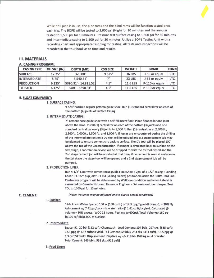
While drill pipe is in use, the pipe rams and the blind rams will be function tested once
each trip. The BOPE will be tested to 2,000 psi (High) for 10 minutes and the annular
tested to 1,500 psi for 10 minutes. Pressure test surface casing to 1,500 psi for 30 minutes
and intermediate casing to 1,500 psi for 30 minutes. Utilize a BOPE Testing Unit with a
recording chart and appropriate test plug for testing. All tests and inspections will be
recorded in the tour book as to time and results.
HI. MATERIALSA. CASING PROGRAM:
CASING TYPE OH SIZE (IN) DEPTH (MD) CSG SIZE WEIGHT GRADE CONN
SURFACE 12.25” 320.00' 9.625" 36 LBS J-55 or equiv STC
INTERMEDIATE 8.75" 5,540.31' 7" 23 LBS J-55 or equiv LTC
PRODUCTION 6.125" 5390.31’ -14,811.52 4.5" 11.6 LBS P-110 or equiv LTC
TIE BACK 6.125" Surf. - 5390.31' 4.5" 11.6 LBS P-110 or equiv LTC
B. FLOAT EQUIPMENT:
1. SURFACE CASING:
9-5/8" notched regular pattern guide shoe. Run (1) standard centralizer on each of
the bottom (4) joints of Surface Casing.
2. INTERMEDIATE CASING:
7" cement nose guide shoe with a self-fill insert float. Place float collar one joint
above the shoe. Install (1) centralizer on each of the bottom (3) joints and one
standard centralizer every (3) joints to 2,500 ft. Run (1) centralizer at 2,500 ft.,
2,300ft., 2,000ft., 1,500 ft., and 1,000 ft. If losses are encountered during the drilling
of the intermediate section a DV tool will be utilized and a 2 stage cement job may
be planned to ensure cement circ back to surface. The DV tool will be placed 100'
above the top of the Chacra formation. If cement is circulated back to surface on the
first stage, a cancelation device will be dropped to shift the dv tool closed and the
2nd stage cement job will be aborted at that time, if no cement is seen at surface on
the 1st stage the stage tool will be opened and a 2nd stage cement job will be
pumped.
3. PRODUCTION LINER:
Run 4-1/2" Liner with cement nose guide Float Shoe + 2jts. of 4-1/2" casing + Landing
Collar + 4-1/2" pup joint + 1 RSI (Sliding Sleeve) positioned inside the 330ft Hard line.
Centralizer program will be determined by Wellbore condition and when Lateral is
evaluated by Geoscientists and Reservoir Engineers. Set seals on Liner Hanger. Test
TOL to 1500 psi for 15 minutes.
C. CEMENT: (Note: Volumes may be adjusted onsite due to actual conditions)
1. Surface:
5 bbl Fresh Water Spacer, 100 sx (160 cu.ft.) of 14.5 ppg Type l-ll (Neat G) + 20% Fly
Ash cement w/ 7.41 gal/sack mix water ratio @ 1.61 cu ft/sx yield. Calculated <®
volume + 50% excess. WOC 12 hours. Test csg to 600psi. Total Volume: (160 cu-
ft/100 sx/ Bbls).TOC at Surface.
2. Intermediate:
Spacer #1: 20 bbl (112 cuft) Chemwash. Lead Cement: 104 bbls, 297 sks, (585 cuft),
12.3 ppg <S> 1.97 cuft/sk yield. Tail Cement: 59 bbls, 254 sks, (331 cuft), 13.5 ppg @
1.3 cuft/sk yield. Displacement: Displace w/ +/- 218 bbl Drilling mud or water.
Total Cement: 163 bbls, 552 sks, (916 cuft)
3. Prod Liner:
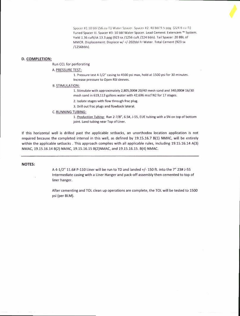
Spacer #1:10 bbl (56.cu-fl) Water Spacer. Spacer 02: 40 bb! 9.5 ppg (224 6 cu ft)
Tuned Spacer III. Spacer 03: 10 bbl Water Spacer. Lead Cement: Extencem System. Yield 1.36 cuft/sk 13.3 ppg (923 sx /1256 cuft /224 bbls). Tail Spacer: 20 BBL of
MMCR. Displacement: Displace w/ +/-202bbl Fr Water. Total Cement (923 sx
/1256bbls).
D. COMPLETION:Run CCL for perforating
A. PRESSURE TEST:
1. Pressure test 4-1/2" casing to 4500 psi max, hold at 1500 psi for 30 minutes.
Increase pressure to Open RSI sleeves.
B. STIMULATION:
1. Stimulate with approximately 2,805,0000 20/40 mesh sand and 340,0000 16/30
mesh sand in 619,113 gallons water with 42,696 mscf N2 for 17 stages.
2. Isolate stages with flow through frac plug.
3. Drill out frac plugs and flowback lateral.
C. RUNNING TUBING:
1. Production Tubing: Run 2-7/8", 6.50, J-55, EUE tubing with a SN on top of bottom
joint. Land tubing near Top of Liner.
If this horizontal well is drilled past the applicable setbacks, an unorthodox location application is not
required because the completed interval in this well, as defined by 19.15.16.7 B(l) NMAC, will be entirely
within the applicable setbacks . This approach complies with all applicable rules, including 19.15.16.14 A(3)
NMAC, 19.15.16.14 B(2) NMAC, 19.15.16.15 B(2)NMAC, and 19.15.16.15. B(4) NMAC.
NOTES:A 4-1/2" 11.6# P-110 Liner will be run to TD and landed +/-150 ft. into the 7" 23# J-55
Intermediate casing with a Liner Hanger and pack-off assembly then cemented to top of
liner hanger.
After cementing and TOL clean up operations are complete, the TOL will be tested to 1500
psi (per BLM).
Sou
th(-
)/N
orth
(+) (
3000
usf
t/in)
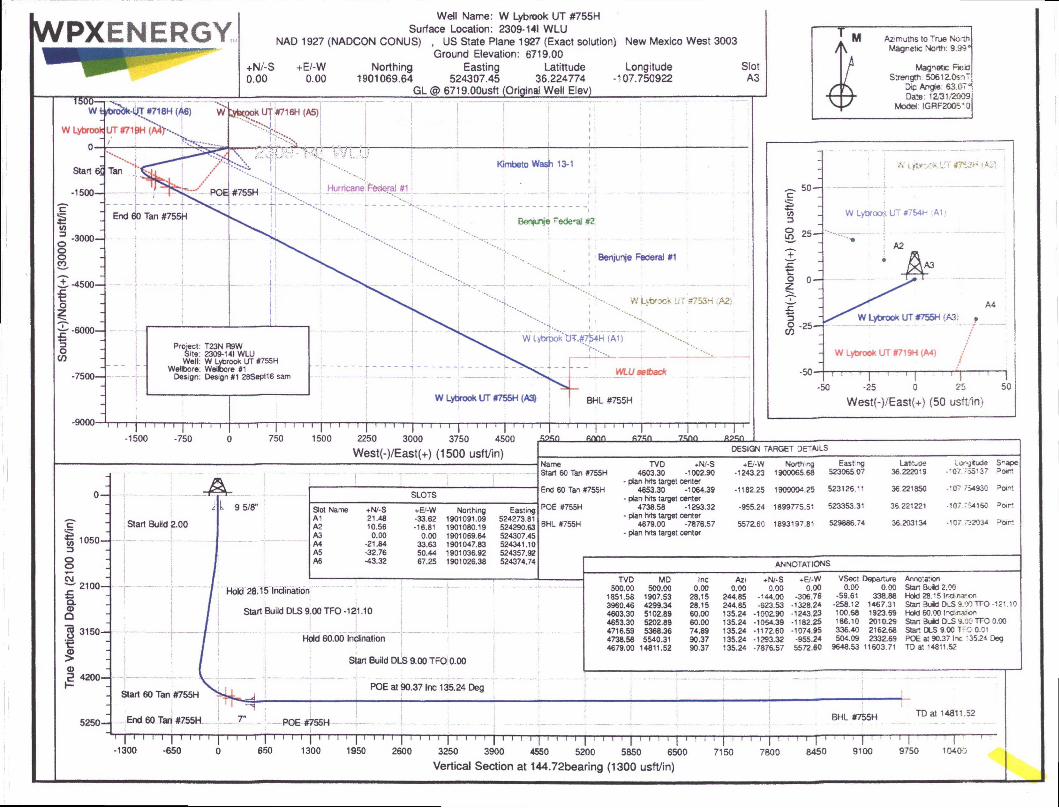
WPXENERGYWell Name: W Lybraok UT #755H
Surface Location: 2309-141 WLUNAD 1927 (NADCON CONUS) , US State Plane 1927 (Exact solution) New Mexico West 3003
Ground Elevation: 6719.00+N/-S +E/-W Northing Easting Latittude Longitude Slot0.00 0.00 1901069.64 524307.45 36.224774 -107.750922 A3
GL @ 6719.00usft (Original Well Elev)
—1f--------------------------------------------
M Ai'muths to True No th/ \ Magnetic North: 9.99*
r Magnetic Fie la/ Strength 5O612.0snT
r |r\ Dip Angie 63.07a
4- -4- Date: 12/31;2009Vy Model IGBF2OO5-0
2250 3000 3750 4500
West(-)/East(+) (1500 usft/in)
c1CO=3Oo▼—CM
SLOTSr111 9 5/8M
Slot Name +N/-S +E/-W Northing EastingA1 21.48 -33.62 1901091.09 524273.81
Start BuSd 2.00 A2 10.56 -16.81 1901080.19 524290.63A3 0.00 0.00 1901069.64 524307.45A4 •21.84 33.63 1901047.83 524341.10A5 -32.76 50.44 1901036.92 524357.92
J Ii i
A6 -43.32 67.25 1901026.38 524374.74
2100-
Q.Oa■§ 3150-
trI0).5 4200-
T
T" Hold 28,15 Indination
Start Build DLS 9.00 TFO -121.10
Hold 60.00 Indination
- Start 60 Tan #755H
DESIGN TAFtGET DETAILS
NameStart 60 Tan #755H
TVD +N/-S4603.30 -1002.90
+E'-W-1243.23
Northing1900065.68
Easing523065.07
Latttwoe36.222019
Lorgitude-'07.T55137
S^ape
End 60 Tan #755H- plan hfts target center
4653.30 -1064.39 -1182.25 1900004.25 523126.11 36.221850 -107.754930
POE #755H- plan hits target center
4738.58 -1293.32 -955.24 1899775.51 523353.31 36.221221 -107 754160 Point
BHL #755H- plan hits target center
4679.00 -7876.57 5572.60 1893197.81 529886.74 36.203134 -107,732034- plan hits target center
Start Build DLS 9.00 TFO 0.00
POE at 90.37 Inc 135.24 Deg
annotations
TVD MD Inc Azi ♦N/-S +E/-W VSect Departure Annotation500.00 500.00 0.00 0.00 0.00 0.00 0.00 0.00 Stan Buid 2.00
1851.58 1907.53 28.15 244.85 -144.00 -306.76 -59.61 338.88 Hold 28.15 Irclmaton3960.46 4299.34 28.15 244.85 -623.53 •1328.2* -258.12 1467.31 Star Buid DlS 9.f» TFO-121.104603.30 5102.89 60.00 135.24 -1002.90 -12*3.23 100.68 1923.69 Hold 60.00 l^chnaJon4653.30 5202.89 60.00 135.24 -1054.39 -1182.25 186.10 2010.29 Stan Bold DlS 9.00 TFO 0.004716.59 5368.36 74.89 135.2^ -1172.60 -1074.95 336.40 2162.68 Start DLS 9.00 TFO 0.014738.58 5540.31 90.37 135.24 -1293.32 -955.24 504.09 2332.69 POE at 90.37 Ire ‘ 35.24 Deg4679.00 14811.52 90.37 135.24 -7876.57 5572.80 9648.53 11603.71 TD at * 4811.52
5250- End 60 Tan #755H
i | I I T
POE #755HBHl #755H TD at 14811.52
-1300
I" | I II
-650 o 650 1300
r~r
1950
T"l I I P-
2600T i i i | i i i i 1 i i r r |" ! r i i | i i i i | t
3250 3900 4550 5200 5850 6500
Vertical Section at 144.72bearing (1300 usft/in)7150 7800 8450 9100 9750 10400

WPX EnergyT23N R9W 2309-141 WLUW Lybrook UT #755H - Slot A3
Wellbore #1
Plan: Design #1 28Sept16 sam
Standard Planning Report28 September, 2016

WPXPlanning Report
DaUba. coMnwa Local Co-ordinate Reference: We# W Lybrook UT #755H (A3) - Slot A3
Company: WPX Energy TVD Reference: GL @ 6719 00usft (Original Well Elev)
Project: T23N R9W MD Reference: GL @ 6719.00usft (Original Well Elev)
Site: 2309-141WLU North Reference: True
W Lybrook UT #755H Survey Calculation Method: Minimum Curvature
Wellbore: UUaIIKam 414W«NID0r8 WlDesign: Design #1 2BSapt16sam
Project T23N R9W
Map System: US State Plane 1927 (Exact solution) System Datum: Mean Sea Level
Geo Datum: NAD 1927 (NADCON CONUS)
Map Zone: New Mexico West 3003
Site
Site Position: Northing: 1,901,091.09 usft Latitude: 36.224833
From: Map Easting: 524.273.81 usft Longitude: -107.751036
Position Uncertainty: 0.00 usft Slot Radius: 13.200 in Grid Convergence: 0.05"
Well W Lybrook UT#755H- Slot A3
Well Position +N/-S -21.48 usft Northing: 1,901,069.64 usft Latitude: 36.224774
+E/-W 33.62 usft Easting: 524,307.45 usft Longitude: -107.750922
Position Uncertainty 0.00 usft Wellhead Elevation: 0.00 usft Ground Level: 6,719.00 usft
—
Wellbore #1
Magnetics Model Name
IGRF200510
Sample Date
12/31/2009
Declination
nDip Angle
OField Strength
(nT)
9.99 63.07 60,612
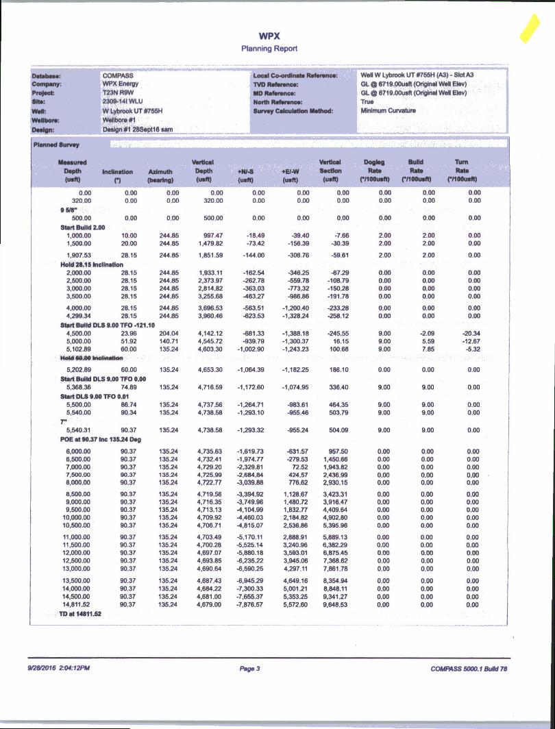
Plan Sections s
MeasuredDepth(usft)
InclinationO
Azimuth(bearing)
VerticalDepth(usft)
+N/-S(usft)
+E/-W(usft)
DoglegRate
(VIOOusft)
BuildRate
(VIOOusft)
■RimRate
(VIOOusft)TFOO Target
0.00 0.00 0.00 0.00 0.00 0.00 0.00 0.00 0.00 0.00
500.00 0.00 0.00 500.00 0.00 0.00 0.00 0.00 0.00 0.00
1,907.53 28.15 244.85 1,851.59 -144.00 -306.76 2.00 2.00 0.00 244.85
4,299.34 28.15 244.85 3,960.46 -623.53 -1,328.24 0.00 0.00 0.00 0.00
5,102.89 60.00 135.24 4,603.30 -1,002.90 -1,243.23 9.00 3.96 -13.64 -121,10 Start 60 Tan #755H
5,202.89 60.00 135.24 4,653.30 -1,064.39 -1,182.25 0.00 0.00 0.00 0.00 End 60 Tan #755H
5,368.36 74.89 135.24 4,716.59 -1,172.60 -1,074.95 9.00 9.00 0.00 0.00
5,540.31 90.37 135.24 4,738.58 -1,293.32 -955.24 9.00 9.00 0.00 0.01 POE #755H
14,811.52 90.37 135.24 4,679.00 -7,876.57 5,572.60 0.00 0.00 0.00 0.00 BHL #755H
9/28/2016 2:04:12PM Page 2 COMPASS 5000.1 Build 78
WPXPlanning Report
Database:Company:
Project:Sits:
WsH:
Wallbora:
Design:
■ OOMPASS
WPX Energy
T23NR8W2309-141WLU
■mybrookUTSTBBH
Wellbore #1Design #1 28SeptH«Sftl
Local Co-ordinate Reference:
TVD Reference:MO Reference:North Reference:Survey Calculation Method:
WsH W Lybrook UT #755H (A3) - Slot A3
GL 0 6719.00ueft (Original Well Elev)
QL a 6719.00usft (Original Well Elev)TrueMinimum Curvature
Planned Survey
Measured Vertical ■■ Vertical Dogleg Build Turn
Depth Inclination Azimuth Depth +N/-S +E/-W Section Rate Rate Rate
(usft) n (bearing) (uslt) (usft) (uaft) (usft) (MOOusft) (MOOusft) (MOOusft)
0.00 0.00 0.00 0.00 0.00 0.00 0.00 0.00 0.00 0.00320.00 0.00 0.00 320.00 0.00 0.00 0.00 0.00 0.00 0.00
9 5/8"500.00 0.00 0.00 500.00 0.00 0.00 0.00 0.00 0.00 0.00
Start Build 2.001,000.00 10.00 244.85 997.47 -18.49 -39.40 -7.66 2.00 2.00 0.001.500.00 20.00 244.85 1,479.82 -73.42 -156.39 -30.39 2.00 2.00 0.00
1,907.53 28.15 244.85 1,851.59 -144.00 -306.76 -59.61 2.00 2.00 0.00
Hold 28.15 Inclination2,000.00 28.15 244.85 1,933.11 -162.54 -346.25 -67.29 0.00 0.00 0.002,500.00 28.15 244.85 2.373.97 -262.78 -559.78 -108.79 0.00 0.00 0.003,000.00 28.15 244.85 2,814.82 -363.03 -773.32 -150.28 0.00 0.00 0.003,500.00 28.15 244.85 3,255.68 -463.27 -986.86 -191.78 0.00 0.00 0.00
4,000.00 28.15 244.85 3,696.53 -563.51 -1,200.40 -233.28 0.00 0.00 0.004,299.34 28.15 244.85 3,960.46 -623.53 -1,328.24 -258.12 0.00 0.00 0.00
Start Build DLS 9.00 TFO -121.104,500.00 23.96 204.04 4,142.12 -681.33 -1,388.18 -245.55 9.00 -2.09 -20.345,000.00 51.92 140.71 4,545.72 -939.79 -1,300.37 16.15 9.00 5.59 -12.675,102.89 60.00 135.24 4,603.30 -1,002.90 -1,243.23 100.68 9.00 7.85 -5.32
Mold 10 JM IncUfliOon
5,202.89 60.00 135.24 4,653.30 -1,064.39 -1,182.25 186.10 0.00 0.00 0.00
Start Build DLS 9.00 TFO 0.005,368.36 74.89 135.24 4,716.59 -1,172.60 -1,074.95 336.40 9.00 9.00 0.00
Start DLS 9.00 TFO 0.015,500.00 86.74 135.24 4,737.56 -1,264.71 -983.61 464.35 9.00 9.00 0.005,540.00 90.34 135.24 4,738.58 -1,293.10 -955.46 503.79 9.00 9.00 0.00
5,540.31 90.37 135.24 4,738.58 -1,293.32 -955.24 504.09 9.00 9.00 0.00
POE at 90.37 Inc 135.24 Deg
6,000.00 90.37 135.24 4,735.63 -1,619.73 -631.57 957.50 0.00 0.00 0.006,500.00 90.37 135.24 4,732.41 -1,974.77 -279.53 1,450.66 0.00 0.00 0.007,000.00 90.37 135.24 4,729.20 -2,329.81 72.52 1,943.82 0.00 0.00 0.007,500.00 90.37 135.24 4,725.99 -2,684.84 424.57 2,436.99 0.00 0.00 0.008,000.00 90.37 135.24 4,722.77 -3,039.88 776.62 2,930.15 0.00 0.00 0.00
8,500.00 90.37 135.24 4,719.56 -3,394.92 1,128.67 3,423.31 0.00 0.00 0.009,000.00 90.37 135.24 4,716.35 -3,749.96 1,480.72 3,916.47 0.00 0.00 0.009,500.00 90.37 135.24 4,713.13 -4,104.99 1,832.77 4,409.64 0.00 0.00 0.00
10,000.00 90.37 135.24 4,709.92 -4,460.03 2,184.82 4,902.80 0.00 0.00 0.0010,500.00 90.37 135.24 4,706.71 -4,815.07 2,536.86 5,395.96 0.00 0.00 0.00
11,000.00 90.37 135.24 4,703.49 -5,170.11 2,888.91 5,889.13 0.00 0.00 0.0011,500.00 90.37 135.24 4,700.28 -5,525.14 3,240.96 6,382.29 0.00 0.00 0.0012,000.00 90.37 135.24 4,697.07 -5,880.18 3,593.01 6,875.45 0.00 0.00 0.0012,500.00 90.37 135.24 4,693.85 -6,235.22 3,945.06 7,368.62 0.00 0.00 0.0013,000.00 90.37 135.24 4,690.64 -6,590.25 4,297.11 7,861.78 0.00 0.00 0.00
13,500.00 90.37 135.24 4,687.43 -6,945.29 4,649.16 8,354.94 0.00 0.00 0.0014,000.00 90.37 135.24 4,684.22 -7,300.33 5,001.21 8,848.11 0.00 0.00 0.0014,500.00 90.37 135.24 4,681.00 -7,655.37 5,353.25 9,341.27 0.00 0.00 0.0014,811.52 90.37 135.24 4,679.00 -7,876.57 5,572.60 9,648.53 0.00 0.00 0.00
TD at 14811.52
0202016 Z04:12PM Page 3 COMPASS 5000.1 Build 78
WPXPlanning Report
DatabaseCompany:
Sits:
wwwll •
»»«-»«■-------vWitDOrviDesign:
COMPASSIASOV CnamwwrA energy T23NR9W
2309-141 WLU
W Lybrook UT #756H.1 mi-Kii ,, siswwlDore #1
Oa^gn #1 28Sapt16 sam...... ,....................
mmmLocal Co-ordinate Reference: Well W Lybrook UT #755H (A3) - Slot A3
TVD Reference: GL ® 6719.00usft (Original Well Elev)
MD Reference: OL @ 6719.00usn (Original Well Elev)
North Reference: True
Survey Calculation Method: Minimum Curvature
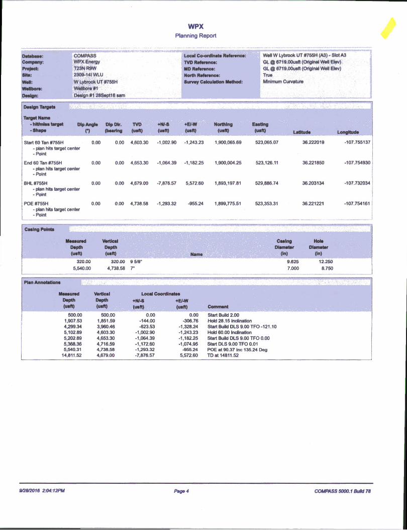
_____________________________Design Targets
Talgat Nsma• hltfmiss target Dip Angle Dip Dtr. TVD +N/-S ♦E/-W Northing Easting• Shape n (bearing (usft) (usft) (usft) (usft) (usft) Latitude L
Start 60 Tan #755H 0.00 0.00 4,603.30 -1,002.90 -1,243.23 1,900,065.69 523,065.07 36.222019 -107.755137- plan hits target center -Point
End 60 Tan #755H 0.00 0.00 4,653.30 -1,064.39 -1,182.25 1,900,004.25 523,126.11 36.221850 -107.754930- plan hits target center- Point
BHL #755H 0.00 0.00 4,679.00 -7,876.57 5,572.60 1,893,197.81 529,886.74 36.203134 -107.732034- plan hits target center -Point
POE #755H 0.00 0.00 4,738.58 -1,293.32 -955.24 1,899,775.51 523,353.31 36.221221 -107.754161- plan hits target center -Point
Casing Points 5
Measured vertical Casing HoleDepth Depth Diameter Diameter(usft) (usft) Name (In) (In)
320.00 320.00 9 5/8" 9.625 12.250
5,540.00 4,738.58 r 7.000 8.750
Plan Annotations
Measured Vertical Local CoordinatesDepth Depth +N/-S +E/-W(usft) (usft) (usft) (usft) Comment
500.00 500.00 0.00 0.00 Start Build 2.001,907.53 1,851.59 -144.00 -306.76 Hold 28.15 Inclination4,299.34 3,960.46 -623.53 *1,328.24 Start Build DLS 9.00 TFO -121.105,102.89 4,603.30 -1,002.90 -1,243.23 Hold 60.00 Inclination5,202.89 4,653.30 -1,064.39 -1,182.25 Start Build DLS 9.00 TFO 0.005,368.36 4,716.59 -1,172.60 -1,074.95 Start DLS 9.00 TFO 0.015,540.31 4,738.58 -1,293.32 -955.24 POE at 90.37 Inc 135.24 Deg
14,811.52 4,679.00 -7,876.57 5,572.60 TD at 14811.52
9/28/2016 2:04:12PM Page 4 COMPASS 5000.1 Butd 70

(Lat/Long) is recorded and full drill log report is completed and filed with WPX. The bed will not be energized for a minimum of 45 days.
After the completion phases and pipeline installation, portions of the project area not needed for operation will be reclaimed. When the wells are plugged, final reclamation will occur within the remainder of the project area. Reclamation is described in detail in the Surface Use Reclamation Plan (Appendix A).
7. METHODS FOR HANDLING WASTE
B.
C.
D.
E.
F.
G.
Cuttings1 Drilling operations will utilize a closed-loop system. Drilling of the horizontal laterals will
be accomplished with water-based mud. All cuttings will be placed in roll-off bins and hauled to a commercial disposal facility or land farm. WPX will follow Onshore Oil and Gas Order No. 1 regarding the placement, operation, and removal of closed-loop systems. No blow pit will be used.
2 Closed-loop tanks will be adequately sized for containment of all fluids.Drilling Fluids
1 Drilling fluids will be stored onsite in above-ground storage tanks. Upon termination of drilling operations, the drilling fluids will be recycled and transferred to other permitted closed-loop systems or returned to the vendor for reuse, as practical. All residual fluids will be hauled to a commercial disposal facility.
Spills1 Any spills of non-freshwater fluids will be immediately cleaned up and removed to an
approved disposal site.Sewage
1 Portable toilets will be provided and maintained during construction, as needed (see Figures 3, 4, 6 and 7 in Appendix B for the location of toilets per wellpad).
Garbage and other waste material1 All garbage and trash will be placed in a metal trash basket. The trash and garbage will
be hauled off site and dumped in an approved landfill, as needed.Hazardous Waste
1 No chemicals subject to reporting under Superfund Amendments and Reauthorization Act Title III in an amount equal to or greater than 10,000 pounds will be used, produced, stored, transported, or disposed of annually in association with the drilling, testing, or completing of these wells.
2 No extremely hazardous substances, as defined in 40 CFR 355, in threshold planning quantities will be used, produced, stored, transported, or disposed of annually in association with the drilling, testing, or completing of these wells.
3 All fluids (i.e., scrubber cleaners) used during washing of production equipment will be properly disposed of to avoid ground contamination or hazard to livestock or wildlife.
Produced Water:1 WPX Energy will dispose of produced water from this well at one of the following
facilities:■ Lybrook Yard WDW #1, API #30-039-27533, NMOCD permit #SWD-907,
operated by Elm Ridge Resources, located in NE Vi, Section 14, Township 23 North, Range 7 West
■ Jillson Federal #1, NMOCD order #R-10168, operated by ConocoPhillips, located in NW %, Section 8, Township 24 North, Range 3 West
- Basin Disposal, permit #NM-01-005, located in the NW Vi, Section 3, Township 29 North, Range 11 West
■ Sunco SWD #001, API #30-045-28653, NMOCD permit SWD-457, operated by Key Energy, located in NW Vi, Section 2, Township 29 North, Range 12 West
2 Water will be hauled by truck. Some produced water may also be used in drilling and completion operations as an alternative disposal method.
/04H, &. 755H
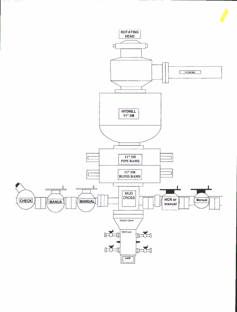
ROTATINGHEAD

Directions front the Intersection of IIS Hwv 550 & US Hwv 64
in Bloomfield, MM to WPX Energy ProuuGiim. LI a VV Lvbrook Unit #75511
1867' FS1. & 674* FKL. Section 14, T23M. R9W. San Juan County, NM
Latitude: 36.224787°iV Longitude: io7.75i536°vV Datum:
From the intersection of US llwy 550 & US llwy 64 in Bloomfield. NM. travel Southerly on US Hwy 550 for 37.8 miles to Mile Marker 113.4:
Go Right (South-westerly) on County Road #7890 for 0.8 miles to fork in roadway;
Go Left (Southerly) remaining on County Road #7890 for 1.3 miles to begin WPX W l.ybrook Unit #71011 proposed access on right-hand side;
Go Right (North-westerly) along WPX W l.ybrook Unit #7101! proposed access for 3412.5' to fork in proposed access:
Go Left (South-westerly) continuing for 1344.8' to staked WPX W L.ybrook Unit #75511 location