state -of -the -art in science & technology - …dasta.teipat.gr/system/files/moke/sofc_sci...
TRANSCRIPT

STATESTATE--OFOF--THE THE --ART INART IN
SCIENCE & TECHNOLOGYSCIENCE & TECHNOLOGY
V. KozhukharovUCTM, Sofia-1756 , Bulgaria
< www. uctm.edu >LAMAR
The Innovation Week on R.E.S. July 01 - 12, 2012, TEI- Patras, Greece
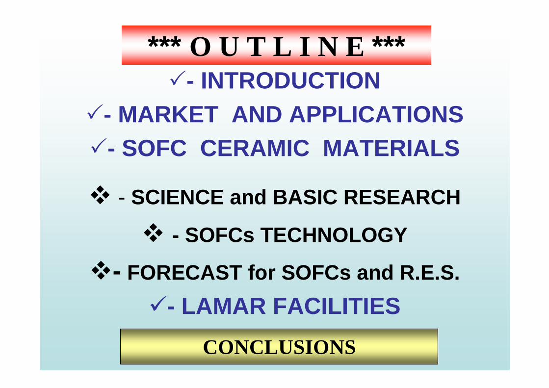
*** O U T L I N E ***�- INTRODUCTION
�- MARKET AND APPLICATIONS�- SOFC CERAMIC MATERIALS
� - SCIENCE and BASIC RESEARCH
� - SOFCs TECHNOLOGY
�- FORECAST for SOFCs and R.E.S.
�- LAMAR FACILITIES
CONCLUSIONS
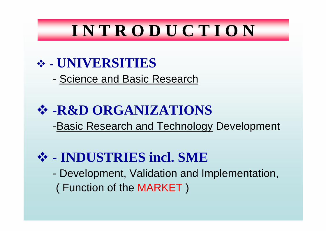
� - UNIVERSITIES- Science and Basic Research
� -R&D ORGANIZATIONS-Basic Research and Technology Development
� - INDUSTRIES incl. SME- Development, Validation and Implementation, ( Function of the MARKET )
I N T R O D U C T I O N

RELATIONS & IMPORTANCE
Science &Basic
Research
Basic Research & Technology Development
& ImplementationLocal &
International


APPLICATION
Civil
Military
Energy Supply of HousesHexis/CH (1 kW), HaldorTopsoe/Dk, Siemens Power,GE /US,McDermott/Cummings/US, FCE/Versa Power/ GTI

• < 1 kWe:• mobile power, e.g. military
• 1-5 kWe:• µ-CHP FC for single houses• recreational, e.g. camping
• 5-10 kWe:• APUs• hybrid vehicles
• 50-250 kWe:• on-site generation, e.g. marine, hospitals, residential• back-up power
• > 1 MWe (preferably as gas turbine hybrids):• power generation
Applications / system size

COMPANIES & SYSTEMS• Europe: Siemens AG & FZ Jülich GmbH, British Gas, R-R, EdF, ECN,Sulzer,
• North America :Argonne N.L., S. Westinghouse Co., Texaco, Ballard
• Asia - ASIA Pacific F.C. & Toto, Toho Co, Tokyo Electric Power and etc.
SIEMENSSIEMENSSIEMENSSIEMENSWestinghouse
Classification:1MWs SOFC/GT Hybrid Power System
Output: AC Electric Power, Hot Water, Continuous
Efficiency: ~ 60%
Noise & Emission: < 70dBA; <0.01kg/MWh
SYSTEM INTEGRATION
Efficiency: > 70% for the market 2010
Efficiency: > 80% for the market 2015
FETC

Efficiency of Different Power-Technologies
MOTIVATION


SOFC CERAMIC MATERIALS
• Raw Materials (Powders)• SOFCs Components and Desigh
- Cathodes- Electrolytes - Anodes- Functional Cathodes/Anodes- Cell Desigh
• Interconnects, Coatings and Sealing• Small Stacks • Test rig ( unit)• Demonstration unit / system
SCIENCE &
TECHNOLOGY
DEVELOPMENT &
IMPLEMENTATION

SCIENCE & BASIC RESEARCH
SOFC - Materials Properties & Performance, Eds. J. F ergus, R. Hui, X. Li, J. Zhang, CRC Press, N.Y, London (2009)
SOFC - Materials Properties & Performance , Eds. J. Fergus, R. Hui, X. Li, J. Zhang, CRC Press, N.Y, London (2009)
T. Kawada, and H. Yokokawa, Materials and Character ization of Solid Oxide Fuel Cells, Key Eng. Materials v.125-126 (199 7) 187
T. Kawada, and H. Yokokawa, Materials and Characterization of Solid Oxide Fuel Cells , Key Eng. Materials v.125-126 (1997) 187
M.Ormerot ‘Catalysis and Electrocatalysis in SOFCs: Internal Reforming and Chemical Cogeneration, Keel Univ., UK, 1st Summer School on SOFC
Technology September 6, 2004, University of Patras, CD-ROM available
M.Ormerot ‘ Catalysis and Electrocatalysis in SOFCs: Internal R eforming and Chemical Cogeneration, Keel Univ., UK, 1st Summer School on SOFC
Technology September 6, 2004, University of Patras, CD-ROM available
C. Vayenas, ‘Introduction to Fuel Cells: Fundamenta ls of Electrochemical Kinetics and Thermodynamics’ Uni. Patras, 1st Summer School on SOFC Technology September 6, 2004, University of Patras, CD-ROM available
C. Vayenas, ‘ Introduction to Fuel Cells: Fundamentals of Electro chemical Kinetics and Thermodynamics ’ Uni. Patras, 1st Summer School on SOFC Technology September 6, 2004, University of Patras, CD-ROM available
�- SOFCs BECKGROUND CONCEPTS

SCIENCE & BASIC RESEARCH
B. Iwanschitz, A. Mai, T. Hocker , ‘Origin and mechanisms of anodedegradation, Helix AG, Züricher Hochschule Winterthur, Swiss , Intern.
Workshop on Degradation Issues of Fuel Cells, 19-21 September, 2007,Crete, Greece
B. Iwanschitz, A. Mai, T. Hocker , ‘Origin and mechanisms of anodedegradation, Helix AG, Züricher Hochschule Winterthur, Swiss , Intern.
Workshop on Degradation Issues of Fuel Cells, 19-21 September, 2007,Crete, Greece
H. Yokokawa et al. ‘Introduction of Fundamental Mec hanism’ AIST, Intern. Workshop on Degradation Issues of Fuel Cells, 19-21 September,
2007,Crete, Greece
H. Yokokawa et al. ‘ Introduction of Fundamental Mechanism’ AIST, Intern. Workshop on Degradation Issues of Fuel Cells, 19-21 September,
2007,Crete, Greece
A. McEvoy , ‘SOFC- Background Concepts’ EPFL, Swiss, 1st Summer School on SOFC Technology September 6, 2004, Univer sity of Patras,GR
A. McEvoy , ‘SOFC- Background Concepts’ EPFL, Swiss, 1st Summer School on SOFC Technology September 6, 2004, Univer sity of Patras,GR
A. Atkitson, ‘Solid State Chemistry of Solid Electr olytes” Imperial College, UK, 1st Summer School on SOFC Technology September 6, 2004,
University of Patras, GR
A. Atkitson, ‘Solid State Chemistry of Solid Electrolytes” Imperial College, UK, 1st Summer School on SOFC Technology September 6, 2004,
University of Patras, GR
� - SOFCs DEGRADATION

Shock wave
High pressure
Solvothermal
C V D
HydrothermalFusion
LASER
Electron
PLASMASputtering
V. Evaporation
Ion
Solid State Reactions
Gasflame
Sol-Gel + Spray
1 atm.P
(atm)
0 t , °C1 2 3 x 1000
ENVIRONMENTAL
ATTRACTIVE
Deposition of thin-film electrolyte and nano- struct ured electrodes by combustion CVD, sol-gel, slurry coating & templateing synthesis methods are actual at present.

�- NMR (NQR), ESR, MÖS
�- OESp, ICP-AES, AASp, UV-VIS, IR Sp, Raman Sp, X-Ray Sp
�- XRD, ED, ND, SAXS, SANS
�- SIMS, RBackScSp
�- XPS, UPS, TEM, SEM, EDX,LEED, AFM, STM, PSp, etc.
(METALLOGRAPHIC)
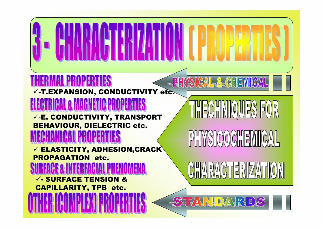
�-T.EXPANSION, CONDUCTIVITY etc.
�-E. CONDUCTIVITY, TRANSPORT BEHAVIOUR, DIELECTRIC etc.
�-ELASTICITY, ADHESION,CRACK PROPAGATION etc.
�- SURFACE TENSION & CAPILLARITY, TPB etc.

�- Ageing under various atmospheres, temperatures and current loads
�- short (performance) and long term (durability) tests
(influence of the water vapour)
�-Thermodynamics and kinetics
of Cr evaporation

Tubular Design – Siemens Westinghouse SWPC
TOTO and Mitshubishi Heavy Industries MHI - 21 kW at 900°C with NG/air
- 190 kW at 950°C with NG/air
Planar Design: Hexis – Swiss
(Heat Exchanger Integrated System => HEXIS)• Circular cells with a diameter of 120 mm
• 1.1. kW at 900°C with NG/air
Planar Design: Rolls Royce IP SOFC (Integrated Planar) - 50 W module
AIR
NG

Operation temperature & Materials
1000 oC 800 oC 600 oC 400 oC
Electrolytesupported
Anodesupported
Metalsupported
TEMPERATURE
Metalsupported
YSZ
Ni+YSZ
LSCF+YSZ
YSZ
Ni+YSZ
LSCF
FeCr FeCr
Ni+SSZ
LSCF
SSZ
Ni+Ceria
LSCF
Ceria
SOFCs REQUIREMENTS

BIPOLAR PLATE APPLICATION
Principle of SOFC design according to GAC- spray concept
Y S Z + LS M - cathode
Y S Z - electrolyte
Y S Z + NiO anode
Porous metallic substrate
Plasma sprayed thin film cell
G. Schiller, Deutsches Zentrum fur Luft- und Raumfahrt (DLR), Stuttgart, Germany

LSM
LSM + YSZ
YSZ
NiO+YSZfine
NiO+YSZcoarse
Cathode CurrentCollector 30 – 70 µm
Cathode FunctionalLayer 10 - 15 µm
Electrolyte Layer5 - 10 µm
Anode FunctionalLayer ~ 5 - 10 µm
Anode Substrate< 1500 µm
S/cm50
25
0.01
1000
500
800oC
σ
State-of-the-Art of SOFCs Layer Structures
d5010µm
1-3µm
2-5µm
1-4µm
3-5µm
45%
20%
0%
20%
35%
graineporosity
H-P.Buchkremer, Cell Manufacture I : Development at Laboratory Scale, 4-th REAL-SOFC Summer School, 3 – 7 September 2007,
Varna, Bulgaria
H-P.Buchkremer, Cell Manufacture I : Development at Laboratory Scale, 4-th REAL-SOFC Summer School, 3 – 7 September 2007,
Varna, Bulgaria
sizeopen

CELL STACK SYSTEM
Cell materials degradationDesign, Contacting,
Cr-evaporationThermomechanical stress
Besides cost and performance , lifetime is the key issue for the commercialuse of SOFCs .
B. Iwanschitz, A. Mai, T. Hocker , ‘Origin and mechanisms of anodedegradation, Helix AG, Züricher Hochschule Winterthur, Swiss ,
Intern. Workshop on Degradation Issues of Fuel Cell s, 19-21September, 2007,Crete, Greece
B. Iwanschitz, A. Mai, T. Hocker , ‘Origin and mechanisms of anodedegradation, Helix AG, Züricher Hochschule Winterthur, Swiss ,
Intern. Workshop on Degradation Issues of Fuel Cell s, 19-21September, 2007,Crete, Greece
Cr-Oxid
MIC

Microstructural degradation
separationdensification
CGO
Ni
delamination reaction

Stability / Degradation of Anodes• Ni sintering
-Temperature influence- Ni-C liquid formation- Water vapors (Ni(OH) vapor)
• Ni Sulfur poisoning- H2S (COS) concentration- S Coverage over Ni/ dissolution into Ni- Ni-S liquid formation
• Redox stability- Effect Water Vapors(?)- Temperature increase on oxidation
SIMS image
Ni/YSZ
Ni/SDC
12C
12C
16O
16O
Important role of water vapor pressures (EIS)O, H and C atoms are dissolved into Ni (dynamic SIMS)

SOFCs TECHNOLOGYD. Eyler, ‘Recent Advances in SOFC Technology’ ALPHEA Co. , 1st
Summer School on SOFC Technology September 6, 2004, Patras, GR.
D. Eyler, ‘ Recent Advances in SOFC Technology ’ ALPHEA Co. , 1st
Summer School on SOFC Technology September 6, 2004, Patras, GR.
R. Steinberger, Worldwide Activities in SOFC: Developers, Manufact urers & Concepts‘’ FZJ, Germany , 4 Summer School ”Manufacturing SOFC-
from the laboratory to the industry-SOFC-2007” Septe mber 5-10, 2007,Ct.Constantin and Elena ,Varna, Bulgaria CD-RO M available
R. Steinberger, Worldwide Activities in SOFC: Developers, Manufactur ers & Concepts ‘’ FZJ, Germany , 4 Summer School ”Manufacturing SOFC-
from the laboratory to the industry-SOFC-2007” Septe mber 5-10, 2007,Ct.Constantin and Elena ,Varna, Bulgaria CD-RO M available
CELL STACK SYSTEM

SOFC Power Plant Concept
M.Jorger , RRFCS report, 4-RealSOFC Summer School, 2-7Sept07,Varna, Bulgaria
Big Plants:SWPC/US (250 to 1000 kW) and RollsRoyce/UK (planning 1 MW)up to 50 kW: SWPC with Fuel Cell Technologies/C, Prototech/N, Honeywell/US,McDermott/US, Global/C, CFCL/AUS

�Description of RRFCS SOFC manufacturing concept– Extrusion
– Screen printing
– Firing
� Costs � Manufacturability
- No manual operation- Wide window of process parameters
� Reproducibility- Quality
Targets => INDUSTRY & TECHNOLOGY
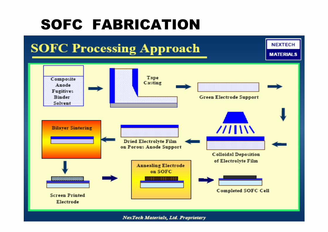
SOFC FABRICATION
METHODSMETHODSMETHODSMETHODS FOR POWDER PRODUCTION
TAPE CASTING
SCREEN PRINTING
CO- SINTHERING
SUBSTRATE
(anode, cathode, electrolyte, bp plate)
CVDTHERMALSPRAYING
SPRAYPYROLYSIS
SOFC CELLSSOFC CELLSSOFC CELLSSOFC CELLS
SINGLE SOFC CELLTESTING & CHARACTERIZATION
STACKS TESTING SYSTEM TESTING

Simple & cost-effective fabrication processes
NIPPON SHOKUBAYNIPPON SHOKUBAYNIPPON SHOKUBAYNIPPON SHOKUBAYNIPPON SHOKUBAYNIPPON SHOKUBAYNIPPON SHOKUBAYNIPPON SHOKUBAY

Ceramic cells and metallic interconnector plates
The choice of a suitable interconnect alloy depends on the SOFC design
In anode-supported designs, promising results have been obtained by vacuum induction (VIM) melting ferritic, high Cr interconnector steels (Crofer 22 APU)
Important research issues for further steel development and qualification• behaviour in C- containing fuel gases and redox atmosphere• resistance under frequent, long-term thermal cycling• stability of very thin interconnects• reducing formation of volatile Cr species• improvements in mechanical properties (creep strength)
P. Ennis, Properties and Production of Steelsfor SOFC Applications, 4-th REAL-SOFC Summer School, 3 – 7 September 2007, Varna, BG
P. Ennis, Properties and Production of Steelsfor SOFC Applications , 4-th REAL-SOFC Summer School, 3 – 7 September 2007, Varna, BG
SOFCs
STEELS

REQUIREMENTS OF SOFC REQUIREMENTS OF SOFC REQUIREMENTS OF SOFC REQUIREMENTS OF SOFC FABRICATION METHODSFABRICATION METHODSFABRICATION METHODSFABRICATION METHODS
• TAPE CASTING METHODS: Tight control of particle size distribution is important; relatively low surface areas needed for high green density.
• CO-SINTERING PROCESSES: Lower sintering temperatures are desired; control of sintering shrinkage rates is essential.
• COLLOIDAL DEPOSITION: Dispersion chemistry is critical; higher surface areas can be tolerated; tailored particle size dist ributions are beneficial.
• PLASMA- SPRAY METHODS: Large particle size and spherical powder morphology are required for optimum flow characteri stics.
• EXTRUSION: Lower surface areas needed for dimensional control and green strength; particle size requirements vary by developer > (t-SOFCs)
• ULTRASONIC SPRAY PYROLYSIS: Lower yield production value is needed to increase; suitable for multilayer /functi onal deposition process
�The best method is this one which is low cost, high- volume manufact uring method (one step production track in air), low temp erature method suitable for automation, PC control of the technological paramet ers for multilayer deposition and on- line robotisation process:
i.e. : To adopt low-cost microelectronic fabrication techniques to SOFC component production ;
: To develop a low- cost tape casting/lamination/screen printing technique for fabricating anode- supported SOFCs.
SUMMARY RECOM.

CELL PERFORMANCECELL PERFORMANCECELL PERFORMANCECELL PERFORMANCE
0.00 0.02 0.04 0.06 0.08 0.10 0.12 0.14 0.16 0.18
0.10.7
0.8
0.9
1.0
1.1
water content, [mol. %] 3 10 20 30
OCV797oC
=1.0036V
OCV792oC
=1.0184V
OCV798oC
=1.0222V
OCV805oC
=1.0640V
no./data08.09.2005 17:0408.09.2005 18:2208.09.2005 19:3308.09.2005 20:58
performance
fuel: H2 870 mil/min / N
2 0 ml/min
H2O from 3 to 30 mol.% (bubbler)
air: 2080 ml/min
cell: ACC: N/A S: Ni/8YSZ (1500 µm) A: Ni/8YSZ (7-10 µm) E: 8YSZ (8-10 µm) IL: N/A C: LSM/8YSZ (10-15 µm) CCC: LSM (60-70 µm)
test no: FG 08start: 01.09.2005facilty: Fid
cell:
3967-1 FZJ/1st gen anod supported diam 8 cm 45 cm2
Cel
l Vol
tage
, [ V
]Current density, [A/cm2]
Study of water vapour pressure influence on V-I charact eristics at 800 oC(short term experiments with different water content ( 3, 10, 20, 30 mol.
%H2O) in fuel at temperatures 700 oC and 900 oC.
0.02 0.04 0.06 0.08 0.10 0.12 0.14 0.16 0.18 0.20
0.10.70
0.75
0.80
0.85
0.90
0.95
1.00
1.05
1.10OCV
700oC=1.052V
OCV750oC
=1.045V
OCV800oC
=1.040V
OCV850oC
=1.025V
OCV900oC
=1.013V
performance
fuel: H2 870 mil/min / N
2 0 ml/min
H2O 3mol.% (bubbler)
air: 2080 ml/min
cell: ACC: N/A S: Ni/8YSZ (1500 µm) A: Ni/8YSZ (7-10 µm) E: 8YSZ (8-10 µm) IL: N/A C: LSM/8YSZ (10-15 µm) CCC: LSM (60-70 µm)
cell:
3968-3 FZJ/1st gen anod supported diam 8 cm 45 cm2
Cel
l Vol
tage
, [ V
]
Current density, [A/cm2]
temperature: 900 850 800 750 700
at 3% H2O – f (T) at 800oC– f (H2O content)

Fuel/cell test : T= 800°C. Fuel is H 2/H2O=97/3 ;oxidant is air.
� No change in cell resistance after several redox
cycles;� No loss in dimensional
stability
RedOx STABILITYRedOx STABILITYRedOx STABILITYRedOx STABILITY
Effect of reduction– oxidation cycling on relative expansion of La 0.4Sr0.6TiO3 (a) and effect of oxidation-reduction cycles on the cell area specific resistance at 0.7 V (b) [20]
�Exposure to reducing environment at 800ºC (corresponding to SOFC anode environment during operation);�Exposure to air during thermal cycling (corresponding to conditions an unprotected anode would experience during system startup and shutdown).

SSA FP6SSA FP6-- 510314 510314 - ANVOC
�AREA 3AREA 3 ----NT&NS, Knowledge based multifunctional NT&NS, Knowledge based multifunctional materials and new production processes and devicesmaterials and new production processes and devicesNMP3-CT-2005-011783MULTIPROTECT
SES6-CT-2003-502612
REAL - SOFC
Application of Nanotechnologies for Separation and Recovery of Volatile Organic Compoun ds
NMP3-CT-2005-011783ENFUGEN http://www.enfugen.net /

SES6-CT-2003-502612REAL - SOFC

[NREL 2011 data]
Map of solar cells efficiencies vs. year of R&D an d companies involved

A view for the future grid of hydrogen production, trans port andutilization with other R.E.S., origin from ENEA .


The mission ofThe mission ofTo develop, identify and investigate of advanced materials and technology, including nanotechnology, in the strategic areas of EDUCATION, RESEARCHEDUCATION, RESEARCH and APPLICATION APPLICATION . The main goal is to meet the needs of a future society, science and industry through activities as follows:
• - innovative education in frontier of the science• - international and interdisciplinary collaboration• - partnerships for a mutual progress • - research on a high level of expert competence• - application activities to the industryi.e. target focused on the MATERIALSMATERIALS with new effects
for the future components, devices and systems.

1- Atmosphere corrosion tests procedures:• Climatic tests :
– Test on shock alteration of the temperature region ( -50º - +55º C). – Test under dry heat treatment > conditions - Test up to 100ºC
• Test in salt – spray camera > due to standard ASTM 117 • Test under low atmosphere pressure > conditions - Pressure from 1 to
700 torrs; Temperature range: from - 60ºC to +120ºC• Test under high humidity level > conditions - Temperature from 20ºC
to 65ºC; Humidity up to 95%• Test under impact of sun radiation > conditions - Irradiation dose of
one test cycle from 8.9 to 26.9 k Wk/m2, Irradiation intensity 1120 W/m2
2- Corrosion tests under special conditions (high temperature corrosion tests )
• Corrosion tests under special conditions (high temperature corr tests) -isothermal treatment in the temperature range from 400o to 900ºC , in H2 atmosphere and other supplementary conditions as the water content, that can be precisely adjusted (N2 and/or H2 + x% H2O ); these experiments can be performed on disc-shaped samples with disc diameter not above than 120 mm and thickness limited to 1mm;
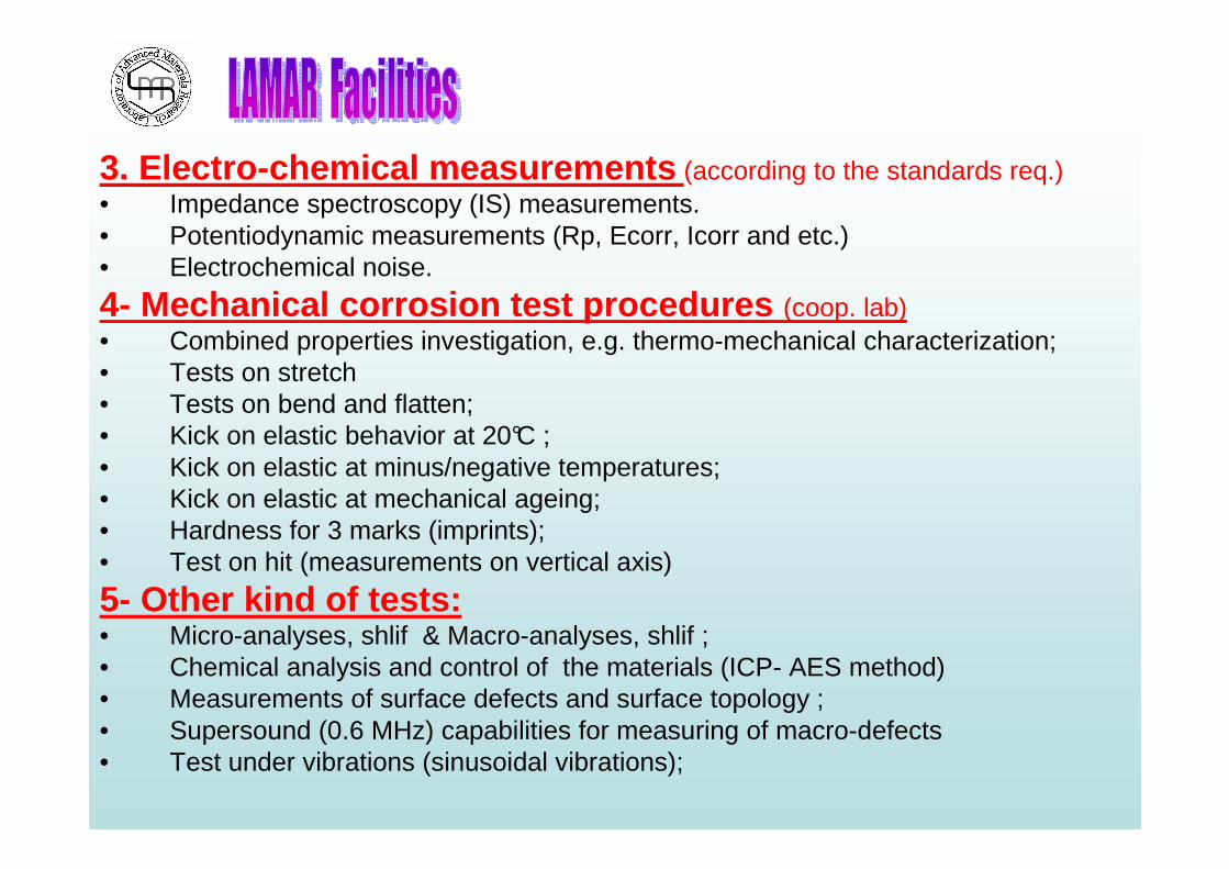
3. Electro-chemical measurements (according to the standards req.)• Impedance spectroscopy (IS) measurements.• Potentiodynamic measurements (Rp, Ecorr, Icorr and etc.)• Electrochemical noise.
4- Mechanical corrosion test procedures (coop. lab)• Combined properties investigation, e.g. thermo-mechanical characterization; • Tests on stretch • Tests on bend and flatten;• Kick on elastic behavior at 20°C ;• Kick on elastic at minus/negative temperatures;• Kick on elastic at mechanical ageing;• Hardness for 3 marks (imprints);• Test on hit (measurements on vertical axis)
5- Other kind of tests:• Micro-analyses, shlif & Macro-analyses, shlif ;• Chemical analysis and control of the materials (ICP- AES method)• Measurements of surface defects and surface topology ;• Supersound (0.6 MHz) capabilities for measuring of macro-defects• Test under vibrations (sinusoidal vibrations);

6- Supporting and additional study with:• Thermodynamic tests of stability by simultaneous TG-DSC and/or TG-DTA
analysis with phase diagrams correlation; Conditions - up to 1600ºC and choice of 2 different gas atmospheres, e.g. N2 and H2; (not simultaneous mass spectroscopy or FT-IR analysis of the vapors is available, at present !)
• Diffraction and spectroscopy tests : X-ray diffraction, IR spectroscopy, X-ray photoelectron spectroscopy, SEM, TEM, EDX, Fe57 -Moessbauer spectroscopy, electron and/or neutron diffraction measurements (INRNE-BAS) and characterization i.e. structural characterization and morphological studies, including diagnostic behavior of the surface treatment;
• Optical microscopy at different magnifications;• AFM surface morphology studies for selected coatings and thin films.
7- SOFCs test rig installation :• The installation is available for short-term (performance) and long-term
(durability) single SOFCs tests under different fuels and conditions. Special tests for IT- SOFCs under adjusted conditions are also possible to be executed. Experiments at temperature regions from 400o to 900ºC, and/or at isothermal treatment at H2 atmosphere and other conditions are available, as well. Tests for SOFCs disc samples at 80mm and 120mm in diameter.
8- Additional laboratory facilities:• Programmable Naber- furnaces up to 1350 oC; CO2 and He-Ne lasers;
ultrasonic spray pyrolysis system; furnaces for polymer film deposition and surface treatment; Netz- milling unit, screen printing unit and UV- photopolymer deposition unit , sol- gel deposition (Deep& Spinning) and etc.

FLORIDA STATE UNIVERSITY
DOHAUNIVERSITY
TOHOKUUNIVERSITY
UNIVERSITYOF TSUKUBA
INSTITUTE OF ORGANIC CATALYSIS AND
ELECTROCHEMISTRY BORESKOV INSTITUTE OF CATALYSIS
DALIAN MARITIME
UNIVERSITY
INSTITUTE OF HIGH TEMPERATURE
ELECTROCHEMISTRY
FLORIDA STATE UNIVERSITY
DOHAUNIVERSITY
TOHOKUUNIVERSITY
UNIVERSITYOF TSUKUBA
INSTITUTE OF ORGANIC CATALYSIS AND
ELECTROCHEMISTRY BORESKOV INSTITUTE OF CATALYSIS
DALIAN MARITIME
UNIVERSITY
INSTITUTE OF HIGH TEMPERATURE
ELECTROCHEMISTRY
INTERCONTINENTALCOLLABORATION

UCTM, Sofia, Bulgaria
CONCLUSIONSCONCLUSIONSCONCLUSIONSCONCLUSIONS
����- For the working stability of SOFCs materials the key aspe ct is to decide the interaction between the basic and acidic cha racter of the substances ;
�- Materials choices are critical issue for SOFC stacks and systems in terms of costs, reliability and on damaging of the st ack ;�- The influences of working conditions on cathode Cr – p oisingmechanisms have to be better understood and to be obj ect of study;�- Anode performance degradation is correlated to its micro structuralChanges ;� - Redox stability is one of the biggest challenge for small scaleSOFC systems for residential use;�- To resolve problems of SOFCs components and stack degra dation it isnecessary to decrease working temperature to 500-600°C;����- System design strongly depends on the requirements of the application.� - FORECAST & LAMAR
����-The progress in SOFCs science and especially in techn ology during the last decades is obviousy high and depends o f the MARKET;