state of the art motor tester & winding analyzer - … · state of the art motor tester &...
TRANSCRIPT
v [email protected] +1 720 491 3580 www.electrominst.com
THE EASIEST TO USE TESTERS ON THE MARKETDELIVERING A NON-DESTRUCTIVE TEST SET
THAT FINDS MORE FAULTSiTIG II
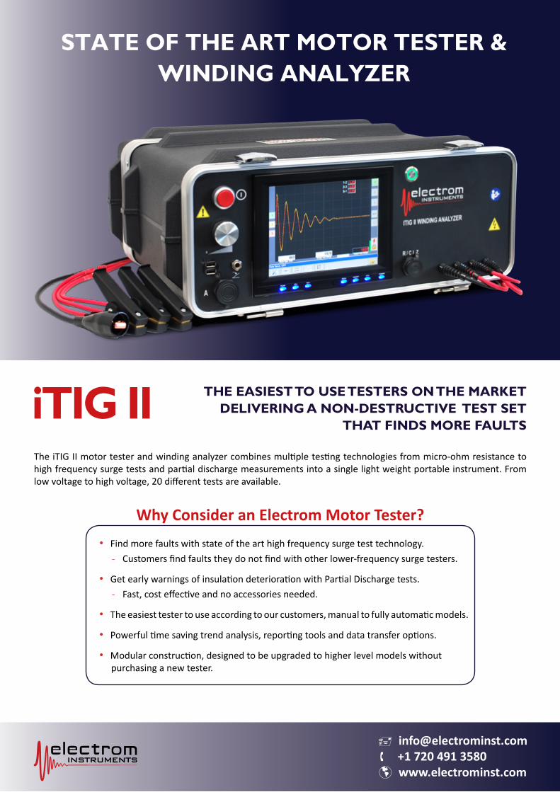
STATE OF THE ART MOTOR TESTER &WINDING ANALYZER
The iTIG II motor tester and winding analyzer combines multiple testing technologies from micro-ohm resistance to high frequency surge tests and partial discharge measurements into a single light weight portable instrument. From low voltage to high voltage, 20 different tests are available.
Why Consider an Electrom Motor Tester?• Find more faults with state of the art high frequency surge test technology.
- Customers find faults they do not find with other lower-frequency surge testers.
• Get early warnings of insulation deterioration with Partial Discharge tests.- Fast, cost effective and no accessories needed.
• The easiest tester to use according to our customers, manual to fully automatic models.
• Powerful time saving trend analysis, reporting tools and data transfer options.
• Modular construction, designed to be upgraded to higher level models without purchasing a new tester.
v [email protected] +1 720 491 3580 www.electrominst.com
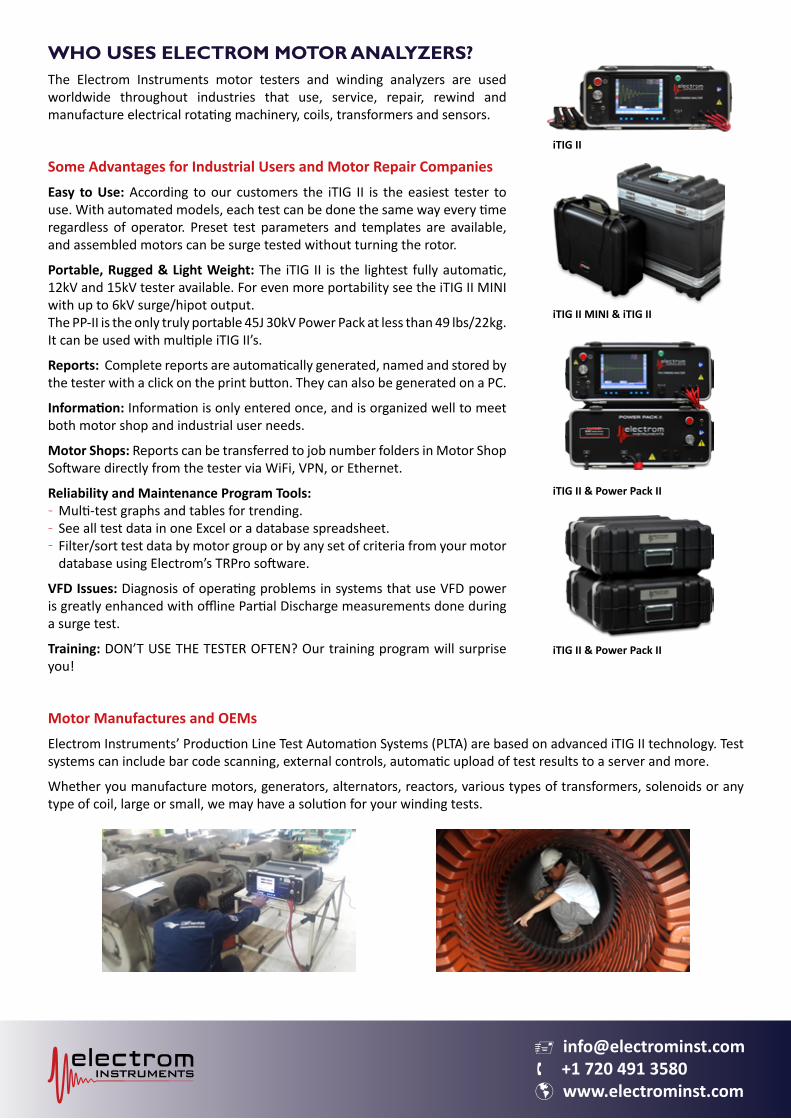
WHO USES ELECTROM MOTOR ANALYZERS?The Electrom Instruments motor testers and winding analyzers are used worldwide throughout industries that use, service, repair, rewind and manufacture electrical rotating machinery, coils, transformers and sensors.
Some Advantages for Industrial Users and Motor Repair CompaniesEasy to Use: According to our customers the iTIG II is the easiest tester to use. With automated models, each test can be done the same way every time regardless of operator. Preset test parameters and templates are available, and assembled motors can be surge tested without turning the rotor.
Portable, Rugged & Light Weight: The iTIG II is the lightest fully automatic, 12kV and 15kV tester available. For even more portability see the iTIG II MINI with up to 6kV surge/hipot output. The PP-II is the only truly portable 45J 30kV Power Pack at less than 49 lbs/22kg. It can be used with multiple iTIG II’s.
Reports: Complete reports are automatically generated, named and stored by the tester with a click on the print button. They can also be generated on a PC.
Information: Information is only entered once, and is organized well to meet both motor shop and industrial user needs.
Motor Shops: Reports can be transferred to job number folders in Motor Shop Software directly from the tester via WiFi, VPN, or Ethernet.
Reliability and Maintenance Program Tools: Multi-test graphs and tables for trending.See all test data in one Excel or a database spreadsheet.Filter/sort test data by motor group or by any set of criteria from your motor database using Electrom’s TRPro software.
VFD Issues: Diagnosis of operating problems in systems that use VFD power is greatly enhanced with offline Partial Discharge measurements done during a surge test.
Training: DON’T USE THE TESTER OFTEN? Our training program will surprise you!
Motor Manufactures and OEMsElectrom Instruments’ Production Line Test Automation Systems (PLTA) are based on advanced iTIG II technology. Test systems can include bar code scanning, external controls, automatic upload of test results to a server and more.
Whether you manufacture motors, generators, alternators, reactors, various types of transformers, solenoids or any type of coil, large or small, we may have a solution for your winding tests.
---
iTIG II MINI & iTIG II
iTIG II & Power Pack II
iTIG II
iTIG II & Power Pack II
v [email protected] +1 720 491 3580 www.electrominst.com
OUTPUTSThe iTIG II series of coil and motor testers come with max output voltages of 4kV, 6kV, 12kV, 12kV-H and 15kV-H. The H model has higher discharge capacitance, and can generate a higher voltage than the 12kV model when the 12kV is maxed out.
Power Packs with maximum output voltages from 18kV to 40kV for testing large higher voltage motors and generators can be added at any time. Our Power Packs are the smallest most portable high voltage test sets available on the market. See Power Pack brochure.
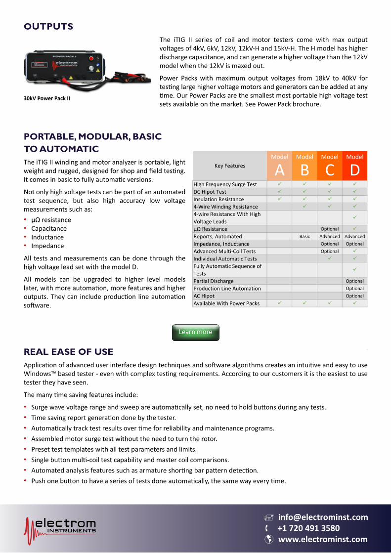
PORTABLE, MODULAR, BASICTO AUTOMATICThe iTIG II winding and motor analyzer is portable, light weight and rugged, designed for shop and field testing. It comes in basic to fully automatic versions.
Not only high voltage tests can be part of an automated test sequence, but also high accuracy low voltage measurements such as:• µΩ resistance• Capacitance• Inductance• Impedance
All tests and measurements can be done through the high voltage lead set with the model D.
All models can be upgraded to higher level models later, with more automation, more features and higher outputs. They can include production line automation software.
REAL EASE OF USEApplication of advanced user interface design techniques and software algorithms creates an intuitive and easy to use Windows™ based tester - even with complex testing requirements. According to our customers it is the easiest to use tester they have seen.
The many time saving features include:
• Surge wave voltage range and sweep are automatically set, no need to hold buttons during any tests.• Time saving report generation done by the tester.• Automatically track test results over time for reliability and maintenance programs.• Assembled motor surge test without the need to turn the rotor.• Preset test templates with all test parameters and limits.• Single button multi-coil test capability and master coil comparisons.• Automated analysis features such as armature shorting bar pattern detection.• Push one button to have a series of tests done automatically, the same way every time.
Model Model Model Model
A B C DHigh Frequency Surge Test
DC Hipot Test
Insulation Resistance
4-Wire Winding Resistance
4-wire Resistance With High Voltage Leads
µΩ Resistance Optional
Reports, Automated Basic Advanced AdvancedImpedance, Inductance Optional OptionalAdvanced Multi-Coil Tests Optional
Individual Automatic Tests
Fully Automatic Sequence of Tests
Partial Discharge OptionalProduction Line Automation OptionalAC Hipot OptionalAvailable With Power Packs
Key Features
30kV Power Pack II
v [email protected] +1 720 491 3580 www.electrominst.com
NON-DESTRUCTIVE SURGE AND HIPOT TESTSWith the iTIG II no manual lead switching is required. Once the operating voltage of the motor is entered, the high frequency surge tests, with IGBT generated fast rising pulses per IEEE 522, can be done automatically. There is no need to further adjust voltage range and sweep (or time base), it is all done by the tester.
• Superior High Frequency Surge PulsesThe iTIG II is the only surge tester capable of generating fully automatic software-controlled surge voltage pulses at high pulse rates up to 50 Hz. This eliminates ionization dissipation present in low frequency surge testers such as those pulsing at 5Hz and lower. As a result, the iTIG II finds more cases of weak insulation and faults, and at lower voltages than low frequency testers.
• Automatic Quick Surge™ and Surge Guard™Enables the user to push a button and let the iTIG II run the test with a controlled and limited number of pulses. Quick Surge™ and Surge Guard™ technology make the tests faster, and ensures the right number of surge pulses are applied for optimal non-destructive performance.
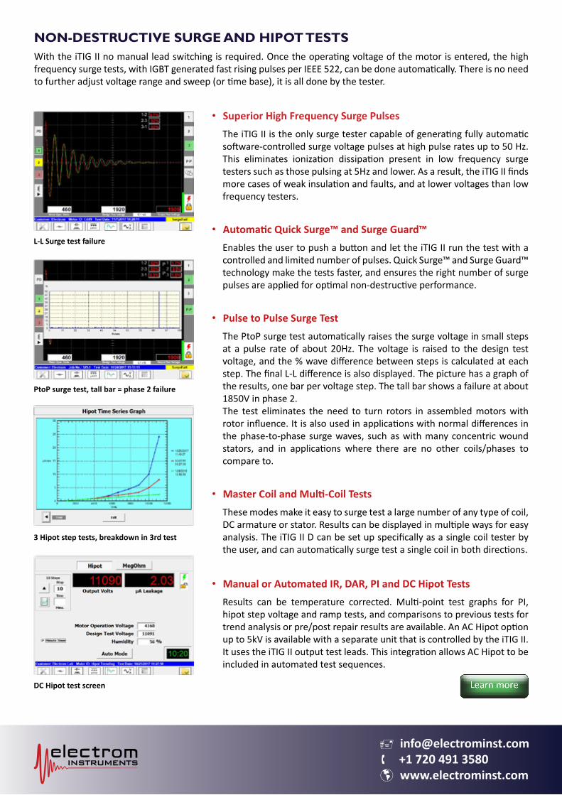
• Pulse to Pulse Surge TestThe PtoP surge test automatically raises the surge voltage in small steps at a pulse rate of about 20Hz. The voltage is raised to the design test voltage, and the % wave difference between steps is calculated at each step. The final L-L difference is also displayed. The picture has a graph of the results, one bar per voltage step. The tall bar shows a failure at about 1850V in phase 2. The test eliminates the need to turn rotors in assembled motors with rotor influence. It is also used in applications with normal differences in the phase-to-phase surge waves, such as with many concentric wound stators, and in applications where there are no other coils/phases to compare to.
• Master Coil and Multi-Coil TestsThese modes make it easy to surge test a large number of any type of coil, DC armature or stator. Results can be displayed in multiple ways for easy analysis. The iTIG II D can be set up specifically as a single coil tester by the user, and can automatically surge test a single coil in both directions.
• Manual or Automated IR, DAR, PI and DC Hipot TestsResults can be temperature corrected. Multi-point test graphs for PI, hipot step voltage and ramp tests, and comparisons to previous tests for trend analysis or pre/post repair results are available. An AC Hipot option up to 5kV is available with a separate unit that is controlled by the iTIG II. It uses the iTIG II output test leads. This integration allows AC Hipot to be included in automated test sequences.
L-L Surge test failure
PtoP surge test, tall bar = phase 2 failure
3 Hipot step tests, breakdown in 3rd test
DC Hipot test screen
v [email protected] +1 720 491 3580 www.electrominst.com
PARTIAL DISCHARGE CAPABILITY
Offline PD measurements provide an early warning of insulation breakdown before a surge test, hipot test or online monitoring indicate an insulation breakdown or failure. It is a great tool to track the condition of equipment over time and can provide an opportunity to lengthen the life of a motor.
In a motor shop or in the field, PD can be a tiebreaker in the determination of pass/fail, and can determine whether to schedule reconditioning /replacement or not.
Partial Discharge tests can also be used to find problems in systems powered by inverter drives (VFD). In coil and rotating equipment manufacturing, partial discharge measurements are used for quality control to confirm that there is no PD or that the PD is below a certain level.
HOW THE iTIG IIDOES PD MEASUREMENTS
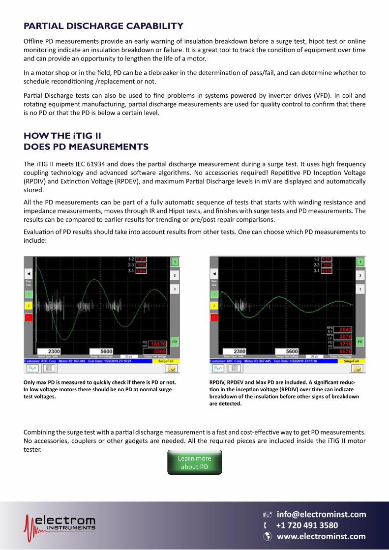
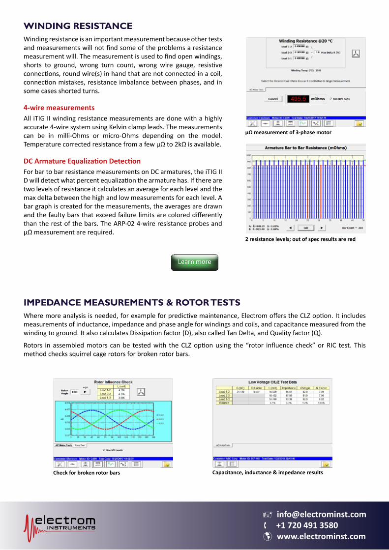
The iTIG II meets IEC 61934 and does the partial discharge measurement during a surge test. It uses high frequency coupling technology and advanced software algorithms. No accessories required! Repetitive PD Inception Voltage (RPDIV) and Extinction Voltage (RPDEV), and maximum Partial Discharge levels in mV are displayed and automatically stored.
All the PD measurements can be part of a fully automatic sequence of tests that starts with winding resistance and impedance measurements, moves through IR and Hipot tests, and finishes with surge tests and PD measurements. The results can be compared to earlier results for trending or pre/post repair comparisons.
Evaluation of PD results should take into account results from other tests. One can choose which PD measurements to include:
Combining the surge test with a partial discharge measurement is a fast and cost-effective way to get PD measurements. No accessories, couplers or other gadgets are needed. All the required pieces are included inside the iTIG II motor tester.
Only max PD is measured to quickly check if there is PD or not. In low voltage motors there should be no PD at normal surge test voltages.
RPDIV, RPDEV and Max PD are included. A significant reduc-tion in the inception voltage (RPDIV) over time can indicate breakdown of the insulation before other signs of breakdown are detected.
v [email protected] +1 720 491 3580 www.electrominst.com
WINDING RESISTANCEWinding resistance is an important measurement because other tests and measurements will not find some of the problems a resistance measurement will. The measurement is used to find open windings, shorts to ground, wrong turn count, wrong wire gauge, resistive connections, round wire(s) in hand that are not connected in a coil, connection mistakes, resistance imbalance between phases, and in some cases shorted turns.
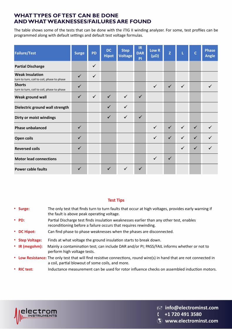
4-wire measurementsAll iTIG II winding resistance measurements are done with a highly accurate 4-wire system using Kelvin clamp leads. The measurements can be in milli-Ohms or micro-Ohms depending on the model. Temperature corrected resistance from a few μΩ to 2kΩ is available.
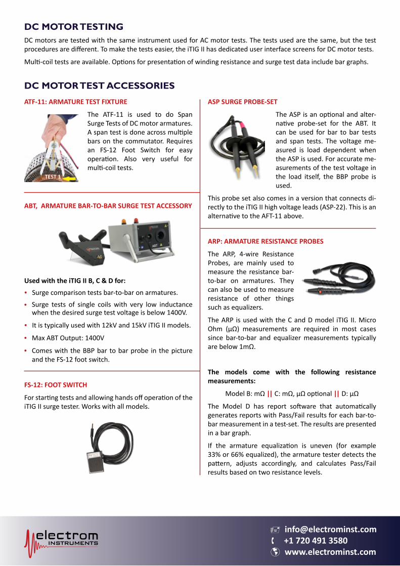
DC Armature Equalization DetectionFor bar to bar resistance measurements on DC armatures, the iTIG II D will detect what percent equalization the armature has. If there are two levels of resistance it calculates an average for each level and the max delta between the high and low measurements for each level. A bar graph is created for the measurements, the averages are drawn and the faulty bars that exceed failure limits are colored differently than the rest of the bars. The ARP-02 4-wire resistance probes and μΩ measurement are required.
IMPEDANCE MEASUREMENTS & ROTOR TESTSWhere more analysis is needed, for example for predictive maintenance, Electrom offers the CLZ option. It includes measurements of inductance, impedance and phase angle for windings and coils, and capacitance measured from the winding to ground. It also calculates Dissipation factor (D), also called Tan Delta, and Quality factor (Q).
Rotors in assembled motors can be tested with the CLZ option using the “rotor influence check” or RIC test. This method checks squirrel cage rotors for broken rotor bars.
2 resistance levels; out of spec results are red
Check for broken rotor bars
µΩ measurement of 3-phase motor
Capacitance, inductance & impedance results
v [email protected] +1 720 491 3580 www.electrominst.com
WHAT TYPES OF TEST CAN BE DONEAND WHAT WEAKNESSES/FAILURES ARE FOUNDThe table shows some of the tests that can be done with the iTIG II winding analyzer. For some, test profiles can be programmed along with default settings and default test voltage formulas.
Failure/Test Surge PDDC
HipotStep
Voltage
IRDAR
PI
Low R (µΩ)
Z L CPhase Angle
Partial Discharge
Weak Insulationturn to turn, coil to coil, phase to phase
Shortsturn to turn, coil to coil, phase to phase
Weak ground wall
Dielectric ground wall strength
Dirty or moist windings
Phase unbalanced
Open coils
Reversed coils
Motor lead connections
Power cable faults
Test Tips
Surge: The only test that finds turn to turn faults that occur at high voltages, provides early warning if the fault is above peak operating voltage.PD: Partial Discharge test finds insulation weaknesses earlier than any other test, enables reconditioning before a failure occurs that requires rewinding.DC Hipot: Can find phase to phase weaknesses when the phases are disconnected.
Step Voltage: Finds at what voltage the ground insulation starts to break down.IR (megohm): Mainly a contamination test; can include DAR and/or PI; PASS/FAIL informs whether or not to perform high voltage tests.Low Resistance: The only test that will find resistive connections, round wire(s) in hand that are not connected in a coil, partial blowout of some coils, and more.RIC test: Inductance measurement can be used for rotor influence checks on assembled induction motors.
•
•
•
••
•
•
v [email protected] +1 720 491 3580 www.electrominst.com
DC MOTOR TEST ACCESSORIES
ATF-11: ARMATURE TEST FIXTURE
The ATF-11 is used to do Span Surge Tests of DC motor armatures. A span test is done across multiple bars on the commutator. Requires an FS-12 Foot Switch for easy operation. Also very useful for multi-coil tests.
ABT, ARMATURE BAR-TO-BAR SURGE TEST ACCESSORY
Used with the iTIG II B, C & D for:
• Surge comparison tests bar-to-bar on armatures.
Surge tests of single coils with very low inductance when the desired surge test voltage is below 1400V.
• It is typically used with 12kV and 15kV iTIG II models.
Max ABT Output: 1400V
Comes with the BBP bar to bar probe in the picture and the FS-12 foot switch.
FS-12: FOOT SWITCH
For starting tests and allowing hands off operation of the iTIG II surge tester. Works with all models.
ASP SURGE PROBE-SET
The ASP is an optional and alter-native probe-set for the ABT. It can be used for bar to bar tests and span tests. The voltage me-asured is load dependent when the ASP is used. For accurate me-asurements of the test voltage in the load itself, the BBP probe is used.
This probe set also comes in a version that connects di-rectly to the iTIG II high voltage leads (ASP-22). This is an alternative to the AFT-11 above.
ARP: ARMATURE RESISTANCE PROBES
The ARP, 4-wire Resistance Probes, are mainly used to measure the resistance bar-to-bar on armatures. They can also be used to measure resistance of other things such as equalizers.
The ARP is used with the C and D model iTIG II. Micro Ohm (μΩ) measurements are required in most cases since bar-to-bar and equalizer measurements typically are below 1mΩ.
The models come with the following resistance measurements:
Model B: mΩ || C: mΩ, µΩ optional || D: µΩ
The Model D has report software that automatically generates reports with Pass/Fail results for each bar-to-bar measurement in a test-set. The results are presented in a bar graph.
If the armature equalization is uneven (for example 33% or 66% equalized), the armature tester detects the pattern, adjusts accordingly, and calculates Pass/Fail results based on two resistance levels.
•
••
DC MOTOR TESTINGDC motors are tested with the same instrument used for AC motor tests. The tests used are the same, but the test procedures are different. To make the tests easier, the iTIG II has dedicated user interface screens for DC motor tests.
Multi-coil tests are available. Options for presentation of winding resistance and surge test data include bar graphs.
v [email protected] +1 720 491 3580 www.electrominst.com
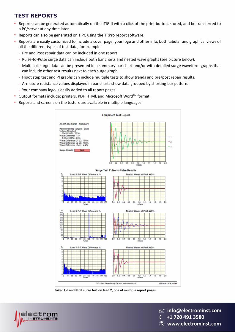
TEST REPORTSReports can be generated automatically on the iTIG II with a click of the print button, stored, and be transferred to a PC/server at any time later.Reports can also be generated on a PC using the TRPro report software.Reports are easily customized to include a cover page, your logo and other info, both tabular and graphical views of all the different types of test data, for example:
Pre and Post repair data can be included in one report.Pulse-to-Pulse surge data can include both bar charts and nested wave graphs (see picture below).Multi coil surge data can be presented in a summary bar chart and/or with detailed surge waveform graphs that can include other test results next to each surge graph.Hipot step test and PI graphs can include multiple tests to show trends and pre/post repair results.Armature resistance values displayed in bar charts show data grouped by shorting-bar pattern.Your company logo is easily added to all report pages.
Output formats include: printers, PDF, HTML and Microsoft WordTM format.Reports and screens on the testers are available in multiple languages.
•
••
---
---
••
Failed L-L and PtoP surge test on lead 2, one of multiple report pages
v [email protected] +1 720 491 3580 www.electrominst.com
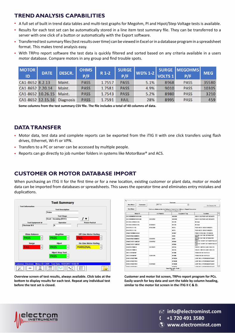
TREND ANALYSIS CAPABILITIES
• A full set of built in trend data tables and multi-test graphs for Megohm, PI and Hipot/Step Voltage tests is available.Results for each test set can be automatically stored in a line item test summary file. They can be transferred to a server with one click of a button or automatically with the Export software.Transferred test summary files (test results over time) can be viewed in Excel or in a database program in a spreadsheet format. This makes trend analysis easy.With TRPro report software the test data is quickly filtered and sorted based on any criteria available in a users motor database. Compare motors in any group and find trouble spots.
DATA TRANSFERMotor data, test data and complete reports can be exported from the iTIG II with one click transfers using flash drives, Ethernet, Wi-Fi or VPN.
• Transfers to a PC or server can be accessed by multiple people.Reports can go directly to job number folders in systems like MotorBase® and ACS.
CUSTOMER OR MOTOR DATABASE IMPORTWhen purchasing an ITIG II for the first time or for a new location, existing customer or plant data, motor or model data can be imported from databases or spreadsheets. This saves the operator time and eliminates entry mistakes and duplications.
•
•
•
•
•
Some columns from the test summary CSV file. The file includes a total of 40 columns of data.
Overview screen of test results, always available. Click tabs at the bottom to display results for each test. Repeat any individual test before the test set is closed.
Customer and motor list screen, TRPro report program for PCs. Easily search for key data and sort the table by column heading, similar to the motor list screen in the iTIG II C & D.
v [email protected] +1 720 491 3580 www.electrominst.com
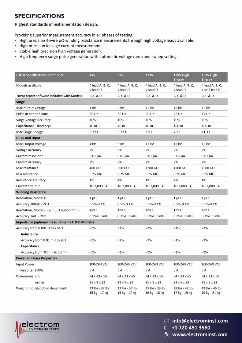
SPECIFICATIONS Highest standards of instrumentation design.
Providing superior measurement accuracy in all phases of testing.• High precision 4-wire μΩ winding resistance measurements through high voltage leads available.• High precision leakage current measurement.• Stable high precision high voltage generation.
High frequency surge pulse generation with automatic voltage ramp and sweep setting.•
iTIG II Specifications per model 4kV 6kV 12kV 12kV High Energy
15kV High Energy
Models available 4 lead A, B, C,7 lead D
4 lead A, B, C, 7 lead D
4 lead A, B, C, 7 lead D
4 lead A, B, C,7 lead D
4 lead A, B, C,4 or 7 lead D
TRPro report software included with Models B, C & D B, C & D B, C & D B, C & D B, C & D
Surge
Max output Voltage 4 kV 6 kV 12 kV 12 kV 15 kV
Pulse Repetition Rate 50 Hz 50 Hz 50 Hz 25 Hz 17 Hz
Surge Voltage Accuracy 10% 10% 10% 10% 10%
Capacitance - discharge 40 nF 40 nF 40 nF 100 nF 100 nF
Max Surge Energy 0.32 J 0.72 J 2.9 J 7.2 J 11.3 J
DC IR and Hipot
Max Output Voltage 4 kV 6 kV 12 kV 12 kV 15 kV
Voltage accuracy 2% 2% 2% 2% 2%
Current resolution 0.01 µA 0.01 µA 0.01 µA 0.01 µA 0.01 µA
Current accuracy 2% 2% 2% 2% 2%
Max resistance 400 GΩ 600 GΩ 1200 GΩ 1200 GΩ 1500 GΩ
Min resistance 0.25 MΩ 0.25 MΩ 0.25 MΩ 0.25 MΩ 0.25 MΩ
Resistance accuracy 4% 4% 4% 4% 4%
Current trip-out 10-2,000 µA 10-2,000 µA 10-2,000 µA 10-2,000 µA 10-2,000 µA
Winding Resistance
Resolution, Model D 1 µΩ 1 µΩ 1 µΩ 1 µΩ 1 µΩ
Accuracy 100µΩ - 2kΩ 0.5%-0.1% 0.5%-0.1% 0.5%-0.1% 0.5%-0.1% 0.5%-0.1%
Resolution, Models B & C (µΩ option for C) 1mΩ 1mΩ 1mΩ 1mΩ 1mΩ
Accuracy 1mΩ - 2kΩ 0.1%±0.5mΩ 0.1%±0.5mΩ 0.1%±0.5mΩ 0.1%±0.5mΩ 0.1%±0.5mΩ
Impedance (optional measurements C & D Models)
Accuracy from 0.001 Ω to 2 MΩ <1% <1% <1% <1% <1%
Inductance
Accuracy from 0.01 mH to 20 H <1% <1% <1% <1% <1%
Capacitance
Accuracy from 0.1 nF to 10 mF <1% <1% <1% <1% <1%
Power and Case Properties
Input Power 100-240 VAC 100-240 VAC 100-240 VAC 100-240 VAC 100-240 VAC
Fuse size (250V) 5 A 5 A 5 A 5 A 5 A
Dimensions, cm 54 x 23 x 55 54 x 23 x 55 54 x 23 x 55 54 x 23 x 55 54 x 23 x 55
inches 21 x 9 x 22 21 x 9 x 22 21 x 9 x 22 21 x 9 x 22 21 x 9 x 22
Weight (model/option dependent) 33 lbs - 37 lbs15 kg - 17 kg
33 lbs - 37 lbs15 kg - 17 kg
35 lbs - 39 lbs16 kg - 18 kg
38 lbs - 42 lbs17 kg - 19 kg
42 lbs - 46 lbs19 kg - 21 kg
v [email protected] +1 720 491 3580 www.electrominst.com
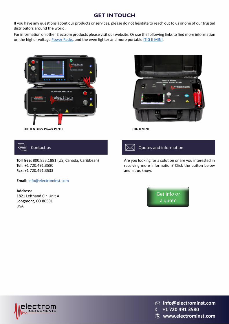
GET IN TOUCHIf you have any questions about our products or services, please do not hesitate to reach out to us or one of our trusted distributors around the world.For information on other Electrom products please visit our website. Or use the following links to find more information on the higher voltage Power Packs, and the even lighter and more portable iTIG II MINI.
Toll free: 800.833.1881 (US, Canada, Caribbean)Tel: +1 720.491.3580Fax: +1 720.491.3533
Email: [email protected]
Address:1821 Lefthand Cir. Unit ALongmont, CO 80501USA
Are you looking for a solution or are you interested in receiving more information? Click the button below and let us know.
Contact us Quotes and information
iTIG II & 30kV Power Pack II iTIG II MINI