state of the art on shield tunnelling in japan- automation ...ota-eng.com/pdf_file/shield...
TRANSCRIPT
1
State of the Art on Shield Tunnelling in Japan- Automation of Shield Tunnelling Yoshihiro Takano, Chiyoda Engineering Consultants Co., LTD., Tokyo, Japan Preface The shield method is a tunnelling method using a steel tube (shield) to support temporarily the face in ground and secure the safety of both of excavation and lining works which are performed inside shield. This method is a mechanized tunnelling method and adopted in tunnelling works in soft ground in the world. 1 History of Development of Shield Tunnelling 1.1 Principle of Shield Method The tunnelling works are divided into the excavation, the construction of lining and the muck transportation, and the shield method adds the shield drive to these three works. The shield method is defined as "the method to construct a tunnel by the excavation and lining works in shield which drives in ground with the function to prevent the collapse of ground", and shield is defined as the machine comprising the hood part, the girder part and the tail part which excavates ground. Generally, shield starts from starting shaft and arrives at arrival shaft. (See Fig.1.1-1.) Shield drives forward with shield jacks. In prototype shields, screw jacks were used and nowadays hydraulic shield jacks are used. During shield drive, shield jacks are pushed out against the lining using segments as the recipient of the thrust force of at the rear part (the shield tail). The excavation work at the face (the front part ) of shield pushed into ground and the lining works at its tail features the shield method. The face must be stabilized to excavate ground. If excavated ground is not self-stable at face, auxiliary methods are necessary or the closed type shield with bulkhead at face described in 1.3.3 shall be adopted. Lining of shield tunnel consists of assembled segments. One piece of segment is an arc in shape. Some piece of segments are assembled as a ring. The excavation is concurrently performed with shield advance and the lining work is performed during shield stopping. Shield tunnel is constructed by the cycle works comprising the excavation concurring with shield advance and the lining.

2
G.L.
Fig.1.1-1 Schematic drawing of shield method
1.2 Development of Shield Method The first application of shield was made by Mark I.Brunel. He excavated a tunnel underpassing Thames River with the shield method and completed it in 1843. (See Fig.1.2-1.) It took 18 years for him to construct the tunnel due to some accidents caused by the bad soil condition. The section of this tunnel was rectangular, and the shield consisted of three containers and the lining was constructed with bricks. In 1869, J.H.Greathead excavated a shield tunnel in London. This tunnel was located in impermeable clay and underpassed Thames River. He used the backfill grouting in this shield method. In 1886,he adopted the compressed air method as an auxiliary method to excavate the shield tunnel in water- bearing sand in City and South London Railway Project. In 1897, J.Price introduced an excavator into a shield. Shield with an excavator enabled more efficient excavation. In Japan, the first slurry shield method was applied to a railway tunnel in 1974 and the first earth pressure balanced shield was applied to a sewer tunnel in 1976. The mechanized and automatic systems have been introduced into these shields. Fig.1.2-1 First Shield developed
by Brunel 1.3 Classification of Shield Methods The shield is divided into the open type shield, the partially closed type shield and the closed type shield. 1.3.1 Open Type Shield The open type shield is a prototype shield and has no bulkhead. Manual shield, partially mechanical shield and mechanical shield belong to this type. The manual shield method is a method that excavation is manually performed by
Starting shaft Segmental lining Shield Arrival shaft

3
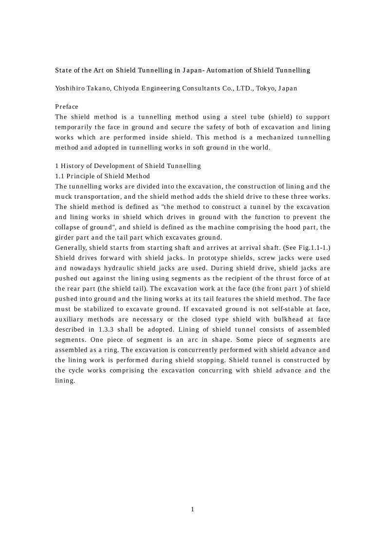
shovel, pickaxe, pick and/or breaker. (See Fig.1.3-1.) This method is the cheapest among the shield methods. The partially mechanical shield is a manual shield that is equipped with mechanical facilities exclusively used for excavation and loading of muck. (See Fig.1.3-2.) This shield enables to make a rapid advance and automated works, compared to the manual shield. Me mechanical shield has a cutterhead with cutter bits. (See Fig.1.3-3.) This shield can make continuous excavation which leads to shortening of construction period and reduction of labors. Cutterhead functions as face-supporting system but this function is imperfect, compared to closed type shield because contact between ground and cutterhead is not perfect due to projected cutter bits and there are slits(openings) for intake of excavated muck. The open type shield method is suitable for dense sand, gravel, hard silt and hard clay which belong to diluvium. Auxiliary methods such as the compressed air method, the dewatering method and/or the chemical injection method are necessary for loose sand, soft silt and soft clay where face is unstable, which belong to alluvium.
Fig.1.3-1 Manual Shield
Fig.1.3-2 Partially Mechanical Shield
4
Fig.1.3-3 Mechanical Shield
1.3.2 Partially Closed Type Shield The partially closed type shield has a bulkhead with openings to support face which is adjacent to face. Blind shield belongs to this type. (See Fig.1.3-4.) Openings play a role of intake of excavated muck. This method is suitable for soft silt and soft clay and unsuitable to sand, hard silt and hard clay because excavated mud must be plasticized to move into shield.
Fig.1.3-4 Blind Shield
1.3.3 Closed Type Shield The closed type shield has a cutterhead and a bulkhead. Slurry shield and earth pressure balanced shield belong to this type. This type shield is available for sand, silt and clay of alluvium or diluvium. The former support face with pressurized slurry and

5
the latter with excavated soil. They are equipped with automatic systems. Details are described in 2.1.1 and 2.1.2. 2 Mechanization and Automation of Shield Tunnelling 2.1 Mechanized Shield Tunnelling The application of the closed type shield has developed the mechanization and the automation of shield tunnelling. 2.1.1 Slurry Shield Slurry shield stabilizes face with pressurized slurry with which cutter chamber is filled. (See Fig.2.1-1.) The pressure of slurry at face shall be a little bit higher than the earth pressure and water pressure from ground. The liquid transportation system of excavated muck features the slurry shield method. Slurry circulates between face and slurry treatment plant on ground surface, as follows. Slurry is supplied from slurry treatment plant to face through feed pipe. Excavated muck at face is taken into slurry not as block but as particle. Slurry returns to slurry treatment plant through discharge pipe and excavated muck is removed and transported to spoil bank. The specific gravity, the viscosity and the sand content of slurry is regulated and slurry is re-supplied to face. This method is available not only for both of soft ground but also for passage under water (sea, river, lake, marsh, e.t.c) and/or near existing pipes or utilities by controlling the pressure, the specific gravity and the viscosity of slurry.
Fig.2.1-1 Slurry Shield
6
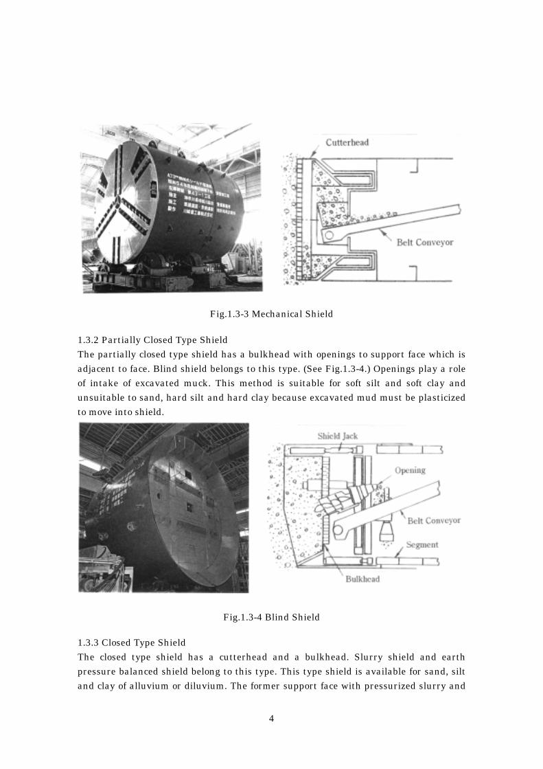
Fig.2.1-2 and 3 shows the circulation of slurry and an example of slurry treatment plant, respectively.
Fig.2.1-2 Schematic Drawing of Circulation of Slurry
Fig.2.1-3 Slurry Treatment Plant

7
2.1.2 Earth Pressure Balanced Shield Earth pressure balanced shield (EPB shield) supports face stably with excavated muck with which cutter chamber is perfectly filled. (See Fig.2.1-4.) EPB shield stabilizes face by balancing the earth pressure and the water pressure from ground and the earth pressure in cutter chamber. The earth pressure in cutter chamber is controlled by the advance rate of shield and the rotation number of screw conveyor through which excavated muck is discharged from cutter chamber. Fig.2.1-5 shows the control system of earth pressure in cutter chamber. EPB shield is available for soft silt and soft clay but unavailable for unflowable soil condition. To excavate such soil that can not be moved from cutter chamber to screw conveyor, EPB shield shall be equipped with the liquid injection system to make excavated muck plastically flowable. This system is a system that water, slurry or slime is injected into cutter chamber and excavated muck in it is forced to be agitated. The agitated muck becomes muddy and flowable to be discharged to screw conveyor. EPB shield with the liquid injection system is available only for alluvial soft ground but also for sand or gravel where blind shield is available.
Fig.2.1-4 Earth Pressure Balanced Shield 2.1.3 Technology for Automation of works Automatic systems are being introduced in shield tunnelling works such as assembling of segments, backfill grouting and mucking. They are the computer-aided systems.

8
Fig.2.1-5 Control System of Earth Pressure in Cutter Chamber
Calculation of Design Earth Pressure
Decision of Design Earth Pressure(P0)
Measurement ofSettlement duringShield Stop
Decision of Shield Jack Speed and Number of Rotation of Screw Conveyor
Shield Drive
Earth Pressure(P1)
in Cutter ChamberIncrease of Number of Rotationof Screw Conveyor
Decrease of Number of Rotationof Screw Conveyor
Cutter TorqueIncrease of Injection Volume Decrease of Injection Volume
Condition of Excavated Muck
Check of Soil Condition,Density and Volume ofInjected Additive,Advance rate of Shield
Spoil Transportation
Good
Larger than Expected Smaller than Expected
Normal
Bad
P1<P
0P1>P
0
P1=P
0

9
1) Automatic segment assembling system The segment assembling work needs skillful labors and is a dangerous work. The automatic segment assembling system has been developed to solve the problem of shortage of skillful labors and secure the safe work. Fig.2.1-6 shows the sequence of the automatic segment assembling system. This system automates the handling, the transportation and the assembling of delivered segments. When computer-aided erector assembles segments, high performance censor controls the positioning of assembled segments and segments to be assembled.
Fig.2.1-6 Sequence of Automatic Segment Assembling System
10
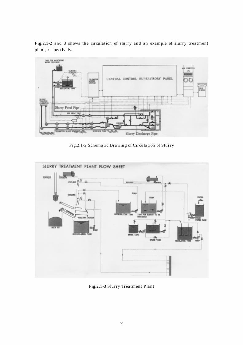
2) Automatic backfill grouting system The shield method cannot avoid gap (tail void) between ground and segmental lining (between excavated diameter and outer diameter of segmental lining). Tail void shall be filled with mortar-based grout behind shield tail without vacant space. The automatic backfill grouting system has been developed to control the pressure and volume of backfill grout automatically in accordance with the volume of tail void. This system supports the simultaneous grouting. Fig.2.1-7 shows this system applied to the EPB shield method.
Fig.2.1-7 Automatic Backfill Grouting System
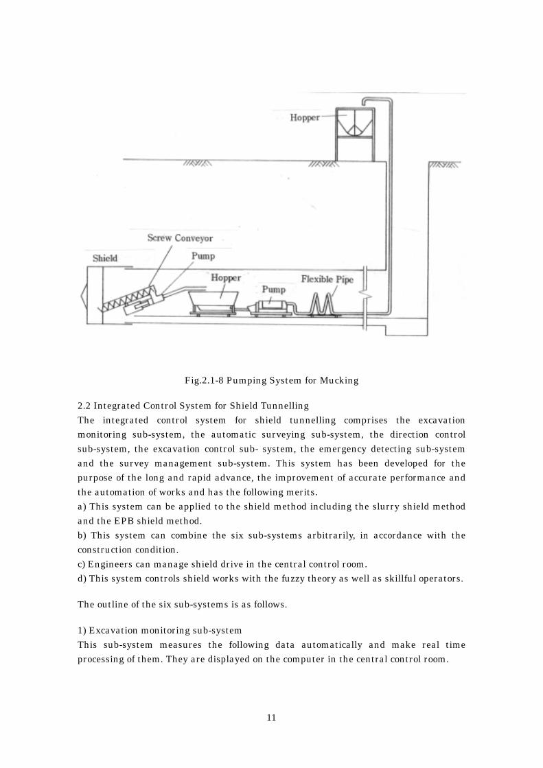
3) Automatic mucking system Muck cars pulled by electric locomotive were used to transport excavated muck from face to shaft. The automatic mucking system using pipe line has been developed to reduce labors and secure safe work. This system is divided into the liquid transportation system, the pumping system and the compressed- air transportation system. This system using pipe line has the following merits. a) Excavated muck can be efficiently transported concurrently with shield advance. b) Horizontal transportation from face to shaft can be combined with vertical transportation from shaft to ground surface. c) Safe and clean work can be secured. The liquid transportation system is applied to the slurry shield method as the slurry transportation system. (Details are described in 2.1.1.) The pumping system and the compressed-air transportation system are applied to the EPB shield method. (See Fig.2.1-8.)
11
Fig.2.1-8 Pumping System for Mucking
2.2 Integrated Control System for Shield Tunnelling The integrated control system for shield tunnelling comprises the excavation monitoring sub-system, the automatic surveying sub-system, the direction control sub-system, the excavation control sub- system, the emergency detecting sub-system and the survey management sub-system. This system has been developed for the purpose of the long and rapid advance, the improvement of accurate performance and the automation of works and has the following merits. a) This system can be applied to the shield method including the slurry shield method and the EPB shield method. b) This system can combine the six sub-systems arbitrarily, in accordance with the construction condition. c) Engineers can manage shield drive in the central control room. d) This system controls shield works with the fuzzy theory as well as skillful operators. The outline of the six sub-systems is as follows. 1) Excavation monitoring sub-system This sub-system measures the following data automatically and make real time processing of them. They are displayed on the computer in the central control room.
12
① Slurry Pressure of Slurry Shield ② Earth Pressure at Cutterhead of EPB Shield ③ Cutter Torque ④ Thrust Force and Speed of Shield Jack ⑤ Probing of Face e.t.c. 2) Automatic surveying sub-system This sub-system surveys the position of shield with the laser survey system or the gyrocompass survey system automatically and calculates its deviation against the designed alignment. Data on surveying are displayed with real time processing and automatically recorded. This makes shield operator accurate direction control of shield. 3) Direction control sub-system This sub-system enables the automatic selection and operation of shield jacks to control the direction of shield in accordance with data on deviation of shield given by the automatic surveying sub-system. The fuzzy theory is applied to the selection of shield jacks. 4) Excavation control sub-system This sub-system makes the following control on shield drive. a) Advance rate of shield b) Backfill grouting work c) Slurry pressure at face (Slurry shield) d) Discharge of slurry in discharge pipe (Slurry shield) e) Earth pressure in cutter chamber (EPB shield) f) Volume of additives injected into cutter chamber (EPB shield) 5) Emergency detecting sub-system This sub-system detects emergency on shield drive and deals with it with the application of the fuzzy theory immediately. 6) Survey management sub-system The deviation of segmental lining measured by surveying with transit can be immediately calculated with computer by using this sub-system. This sub-system gives the coordinate of measured tunnel center. This sub-system makes complicate processing of survey easy. Fig.2.2-1 shows the display of computer of the sub-systems of the integrated control system for shield tunnelling

13
Excavation Monitoring Sub-System Automatic Surveying Sub-System
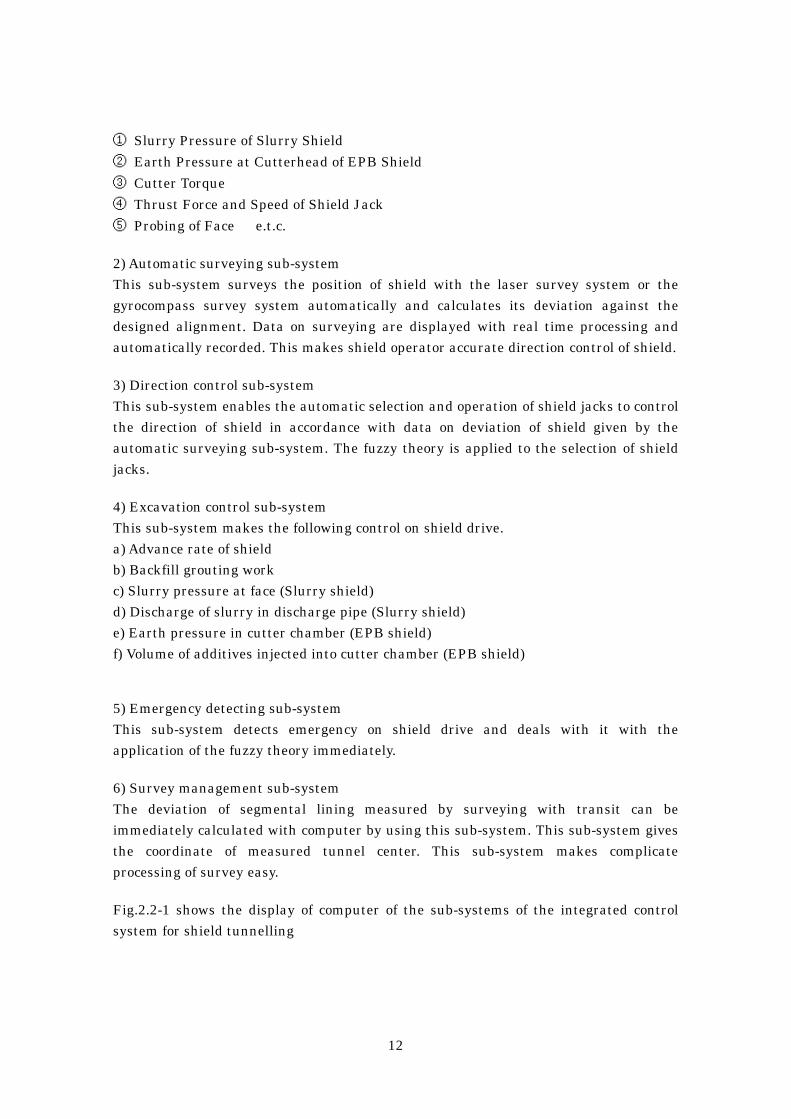
Direction Control Sub-System Excavation Control Sub-System Emergency Detecting Sub-System Fig.2.2-1 Display of Computer of Sub-Systems of Integrated Control System for Shield Tunnelling 3 New Technology of Shield Tunnelling 3.1 Extruded Concrete Lining Method (ECL Method) In the case of the conventional shield method, after excavating ground with shield, segments are assembled at its tail part and tail void is filled with backfill grouting. Contrary to this method, in the case of the ECL method, fresh concrete for lining is placed at shield tail without using segments. For this purpose, shield for the ECL method is equipped with tubing shutters at the back of shield and stop end form between shield skin plate and tubing shutter. This method constructs concrete lining
14
without making tail void and loosening ground by continuously placing concrete under the designed pressure concurrently with shield advance. The thrust force of shield jacks is transmitted through the friction between concrete and tubing shutters. Fig.3.1-1 is the schematic drawing of the ECL method.
Fig.3.1-1 ECL Method 3.2 Novel Material Shield-cuttable Tunnel-Wall System (NOMST) Shield tunnels are mainly constructed in soft ground with high ground water pressure. When shield starts from a shaft or arrives at a shaft, their walls have to be broken by hand. This work possibly leads to gush of ground water into shaft, cave-in or settlement of ground surface. Ground improvement of the outer space of wall is necessary to prevent above-mentioned troubles. Both works of wall-breaking and ground improvement are subject to prolongation of construction period. The NOMST has resolved these problems. This system enables shield to start or arrive by directly cutting the entrance or exit part of wall of shaft with cutter bits of shield without the ground improvement work. In the NOMST, this part of wall is constructed with precast concrete beams using Carbon Fiber Reinforced Plastic (CFRP) as reinforcement and limestone as coarse aggregate. CFRP reinforced concrete (CFRP-RC) can be easily cut by cutter bits of shield. Beams of CFRP-RC (NOMST beams) in the vertical direction which are jointed with steel beams at both ends functions as retaining wall at entrance or exit part. Fig.3.2-1 shows the starting method by the NOMST.

15
Fig.3.2-1 Starting Method by NOMST 3.3 Analysis of Ground Movement The finite element method (the FEM) using computer enables the accurate analysis of ground movement induced by shield tunnelling. Usually, the two dimensional FEM is used in consideration of its cost performance because it is assumed that tunnel lining is in plane-strain state. This method is numerical analysis and application of the mechanics of continuous body on the assumption that a block of soil would be a triangular or quadrangular plane stress element having parameters of the unit weight, the elastic modulus, the Poisson’s ratio and a tunnel lining is a beam element having parameters of the unit weight, the area, the moment of inertia and the elastic modulus. To evaluate the three-dimensional effect of tunnel lining and ground, the conception on the stress release is used in this method. This conception is as follows. 30 or 40 % of earth pressure and water pressure would be released at face when tunnel is excavated. It is sustained by ground at face itself. The rest of stress of ground would be sustained by both of lining and ground. Fig.3.3-1 shows the steps of analysis by the FEM.

16
Fig.3.3-1 Steps of FEM 2nd step: 30~40 % of earth pressure and water pressure is loaded on excavated ground surface at face and is sustained by ground. 3rd step: 60~70 % of earth pressure and water pressure is loaded on lining and supported by lining and ground. Nowadays, the development of three-dimensional FEM or the distinct element method (the DEM) in which adjacent blocks of soil are combined with spring and damper. Analysis result calculated by the FEM shall be compared with measurement result in site to establish the more rational and economical design method. 4 Shield Tunnelling in Future There are many existing pipes, tunnels and foundations in underground of urban areas of Japan. In such condition, complicate alignment including sharply curved one is demanded to construct a new tunnel or non-circular section such as rectangle, oval or multi-faced circular section is done to excavate an economical section. Moreover, tunnels shall have to be constructed in deep underground under very high water pressure in future. Then, long distance shield driving shall be required. Such tunnels shall be excavated by more mechanized shield in more dangerous working condition and the automatic shield tunnelling shall be more necessary.
17
This paper is published in the proceedings of Modern Engineering and Technology Seminar CIE, 1996. All of copyrights are reserved by Yoshihiro Takano from Chiyoda Engineering Consultants Co., LTD, the author of this paper.