state project no. 56-299 town project no. 06-44 … · safely carry the hl-93 legal load. design...
TRANSCRIPT

REHABILIATION OF BRIDGE NO. 05491
BAILIWICK ROAD OVER BYRAM RIVER
GREENWICH, CONNECTICUT
STATE PROJECT NO. 56-299
TOWN PROJECT NO. 06-44
STRUCTURE TYPE STUDY REPORT
OCTOBER 2011
Prepared By:
Dewberry-Goodkind, Inc.
59 Elm Street, Suite 101
New Haven
Structure Type Study
Rehabilitation of Bridge No. 05491
Bailiwick Road over Byram River
Greenwich, Connecticut
TOC-1
Table of Contents
Description Page
1. Project Description 1
2. Bridge Evaluation Methodology 2
3. Proposed Bridge Rehabilitation/Replacement 4
3.1 Alternative 1: Bridge Replacement 4
3.1.1 Design 4
3.1.2 Constructability 5
3.1.3 Cost Estimate 5
3.1.4 Benefits 5
3.2 Alternative 2: Bridge Rehabilitation with addition of Relief Culverts 6
3.2.1 Design 6
3.2.2 Constructability 7
3.2.3 Cost Estimate 7
3.2.4 Benefits 8
4. Summary, Conclusions & Recommendations 8
Appendix A – Location Map
Appendix B – Photos
Appendix C – Sketches
Appendix D – Construction Schedule
Appendix E – Cost Estimate
Appendix F – Alternative 1 Superstructure Computations
Appendix G – Alternative 2 Arch Analysis & Load Rating Computations

Structure Type Study
Rehabilitation of Bridge No. 05491
Bailiwick Road over Byram River
Greenwich, Connecticut
1
Report
1. PROJECT DESCRIPTION
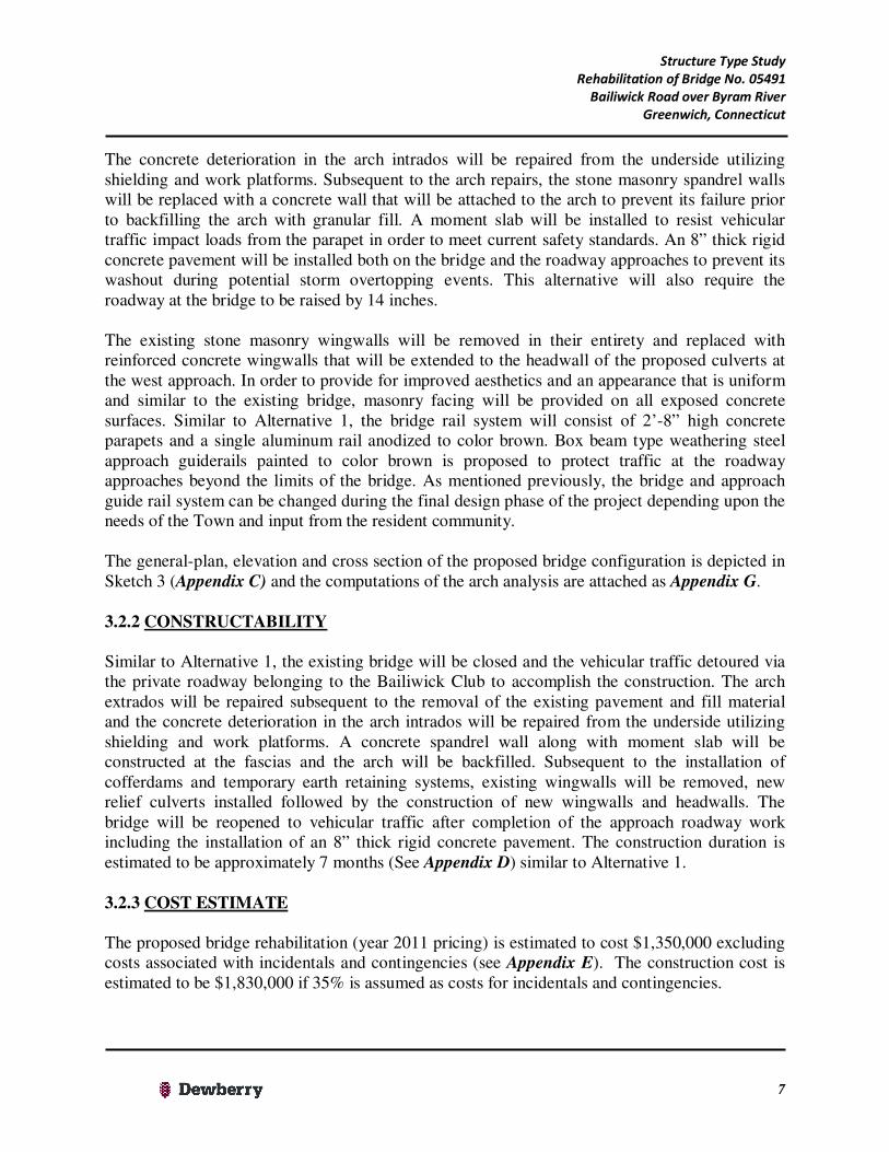
Bridge No. 05491 carries Bailiwick Road, an urban local road, over the Byram River in the Town of Greenwich (Town), Connecticut. The bridge is located approximately fifty-five feet west of the intersection of Bailiwick Road with Riversville Road (see Location Map, Appendix
A) and provides the only official access to a community of approximately 200 residents. The Average Daily Traffic (ADT) on the bridge is 595 vehicles (Year 2010) based on information available with the Connecticut Department of Transportation (ConnDOT). The 32 foot long (chord length) single span arch shaped bridge carries one lane of vehicular traffic in the eastbound and westbound directions over a roadway with a 30 foot width. In addition, the bridge carries an approximately 5’-0” wide grass walkway along the south fascia. The bridge is located within the limits of a slightly curved horizontal roadway alignment with a crest vertical curvature. According to information available with ConnDOT, the bridge was originally constructed in 1970. The bridge superstructure consists of a reinforced concrete deck arch with masonry facing present on the fascias. Spandrel walls comprising of grouted stone masonry retains the fill above the arch and act as parapets at the two fascias. The spandrel walls/parapets are of “gravity” type construction and cannot support current vehicular impact loads since they are not positively attached to the deck. The arches are supported by reinforced concrete footings which are founded on bedrock based on information contained in the original design plans. The approach roadway is contained by stone masonry wingwalls with parapets.
During a major storm event that took place on April 15, 2007, the Bailiwick Road Bridge which is hydraulically deficient, sustained damage as a result of the Byram River overtopping the bridge. The damage included the detachment of the north (i.e. upstream) parapet and rail system from the bridge structure and failure of the bituminous concrete pavement resulting in the closure of the bridge. The Town was able to detour traffic via a private roadway belonging to Bailiwick Club (see Aerial View of Project Site, Appendix A). Subsequently, the Town was able to reopen the bridge by installing temporary precast concrete barriers along the fascias to act as parapets and by reconstructing the roadway pavement over the arch bridge. The Town has since replaced the storm damaged parapet with funding available from the Federal Emergency Management Agency (FEMA).
Photos of the existing bridge are attached as Appendix B. A general-plan, elevation and cross section of the existing bridge is depicted as Sketch 1 in Appendix C.
Since a formal load rating evaluation has not been performed by ConnDOT, the Bailiwick Road Bridge is assumed to have an inventory load rating capacity of 34 tons for an HS-20 vehicle based on judgment. This is slightly less than the minimum 36 tons required per the American

Structure Type Study
Rehabilitation of Bridge No. 05491
Bailiwick Road over Byram River
Greenwich, Connecticut
2
Association of State Highway & Transportation Officials (AASHTO) Standards. A visit to the bridge site and review of the 2009 ConnDOT Inspection Report (subsequent to repairs made by the Town) indicates the superstructure (i.e. concrete arch) and the substructures (i.e. concrete arch walls, footings and masonry wingwalls) to be in “Satisfactory” condition. The underside of the arch exhibits isolated cracks with efflorescence and areas with honeycombing while the masonry facing exhibits missing/deteriorated mortared joints. There are a few spalls and voids present near the water line at the concrete arch walls while the masonry wingwalls exhibit missing/deteriorated mortared joints. No formal in-depth inspection was performed as part of the Structure Type Study. Since the repairs performed subsequent to the 2007 storm damage are temporary in nature and the bridge provides the only official access to the residential community, the bridge is being studied for rehabilitation/replacement. The primary goals of the project are to improve the hydraulic capacity of the bridge to provide relief from flooding arising from lower frequency storm events and to ensure that bridge/roadway can be reopened quickly to vehicular traffic subsequent to a higher frequency overtopping event similar to that of the April 2007 storm. Based on a preliminary hydraulic analysis performed by Dewberry, the results of which were summarized in a memorandum and submitted to the Town/ConnDOT in August 2011, the following alternatives were proposed for investigation in the Structure Type Study:
1. Alternative 1 – Bridge replacement 2. Alternative 2 – Bridge rehabilitation with addition of relief culverts 3. Alternative 3 – Bridge rehabilitation with lowering of west approach roadway
Since the preliminary hydraulic analysis indicated no reductions in the upstream water surface elevations, compared to existing conditions, that would alleviate flooding arising from lower frequency storm events by simply lowering the west approach roadway, Alternative 3 was not investigated further.
A geotechnical investigation comprising of three soil borings was initiated to obtain information about the soil conditions in order to determine the existing/proposed foundation capacities, verify the ability of the foundations to withstand design scour conditions and help in determining the need for any countermeasures. The boring locations are depicted in Sketches 2 and 3, in Appendix C. Since shallow bedrock elevations were observed with the soil borings, scour is not anticipated to be a concern on this project. The results of the geotechnical investigations will be submitted separately to the Town as an independent Foundations Report. 2. BRIDGE EVALUATION METHODOLOGY
The ability of a bridge to carry legal loads is determined from the minimum load rating capacity of its member components. The legal load for new bridge construction is an HL-93 design vehicle (see Figure 1) according to the AASHTO LRFD Design Specifications. The HL-93 loading comprises of:

Structure Type Study
Rehabilitation of Bridge No. 05491
Bailiwick Road over Byram River
Greenwich, Connecticut
3
a) Design Truck or Design Tandem whichever produces maximum forces; combined with b) Design Lane Load
The Design Truck is a 3-axle 28 to 44 foot long vehicle weighing 36 tons while the Design Tandem is a 2-axle 4 foot long vehicle weighing 25 Tons. The Design Lane load is a uniform load of 640 pounds/feet applied in combination with the aforementioned loads. The governing load ratings are determined for an "as-inspected" condition of the bridge accounting for section losses (if present) and are calculated at two levels, Inventory and Operating. The Inventory Rating represents an allowable live load that can safely use the bridge for an “indefinite” period of time. The Operating Rating describes the “maximum” permissible live load to which the bridge may be subjected. Unlimited usage of the bridge by vehicles at the Operating level will shorten the useful life of the structure. The Inventory Rating Factor for a member is obtained by subtracting the dead load effects on the member from the member capacity and dividing the results by the effects of the HL-93 live loads. The calculated dead loads are increased by 25% (components and attachments to the bridge) to 50% (wearing surface on the bridge) while the live loads are increased by 75% to account for uncertainties. In summary,
Inventory Rating Factor = Member Capacity - 1.25 to 1.50*(Dead Loads)
1.75*(Live Loads)
An Inventory Rating Factor greater than or equal to 1.0 indicates the ability of the member to safely carry the HL-93 legal load.
Design Truck + Lane Load
Design Tandem + Lane Load
Figure 1 – AASHTO HL-93 Vehicle
Structure Type Study
Rehabilitation of Bridge No. 05491
Bailiwick Road over Byram River
Greenwich, Connecticut
4
3. PROPOSED BRIDGE REPLACEMENT/REHABILITATION
3.1 ALTERNATIVE 1: BRIDGE REPLACEMENT
3.1.1 DESIGN
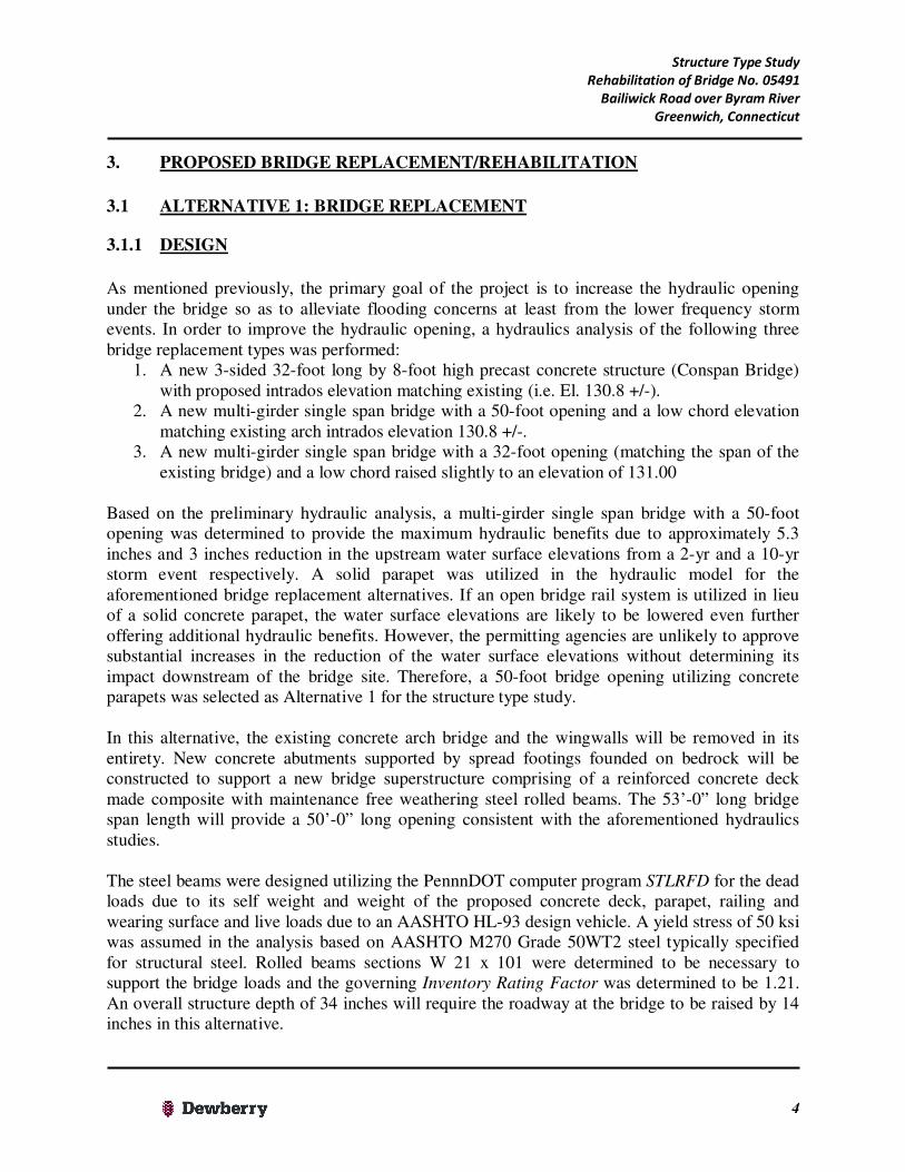
As mentioned previously, the primary goal of the project is to increase the hydraulic opening under the bridge so as to alleviate flooding concerns at least from the lower frequency storm events. In order to improve the hydraulic opening, a hydraulics analysis of the following three bridge replacement types was performed:
1. A new 3-sided 32-foot long by 8-foot high precast concrete structure (Conspan Bridge) with proposed intrados elevation matching existing (i.e. El. 130.8 +/-).
2. A new multi-girder single span bridge with a 50-foot opening and a low chord elevation matching existing arch intrados elevation 130.8 +/-.
3. A new multi-girder single span bridge with a 32-foot opening (matching the span of the existing bridge) and a low chord raised slightly to an elevation of 131.00
Based on the preliminary hydraulic analysis, a multi-girder single span bridge with a 50-foot opening was determined to provide the maximum hydraulic benefits due to approximately 5.3 inches and 3 inches reduction in the upstream water surface elevations from a 2-yr and a 10-yr storm event respectively. A solid parapet was utilized in the hydraulic model for the aforementioned bridge replacement alternatives. If an open bridge rail system is utilized in lieu of a solid concrete parapet, the water surface elevations are likely to be lowered even further offering additional hydraulic benefits. However, the permitting agencies are unlikely to approve substantial increases in the reduction of the water surface elevations without determining its impact downstream of the bridge site. Therefore, a 50-foot bridge opening utilizing concrete parapets was selected as Alternative 1 for the structure type study. In this alternative, the existing concrete arch bridge and the wingwalls will be removed in its entirety. New concrete abutments supported by spread footings founded on bedrock will be constructed to support a new bridge superstructure comprising of a reinforced concrete deck made composite with maintenance free weathering steel rolled beams. The 53’-0” long bridge span length will provide a 50’-0” long opening consistent with the aforementioned hydraulics studies. The steel beams were designed utilizing the PennnDOT computer program STLRFD for the dead loads due to its self weight and weight of the proposed concrete deck, parapet, railing and wearing surface and live loads due to an AASHTO HL-93 design vehicle. A yield stress of 50 ksi was assumed in the analysis based on AASHTO M270 Grade 50WT2 steel typically specified for structural steel. Rolled beams sections W 21 x 101 were determined to be necessary to support the bridge loads and the governing Inventory Rating Factor was determined to be 1.21. An overall structure depth of 34 inches will require the roadway at the bridge to be raised by 14 inches in this alternative.

Structure Type Study
Rehabilitation of Bridge No. 05491
Bailiwick Road over Byram River
Greenwich, Connecticut
5
Reinforced concrete wingwalls will be designed to contain the approach roadway. A rigid concrete pavement will be utilized to construct the roadway approaches in order to eliminate pavement washouts during storm events and to facilitate a quicker reopening of the bridge subsequent to overtopping events. To improve aesthetics, exposed concrete surfaces can either be provided with a masonry facing or less expensive form liners can be utilized to provide an appearance of stone masonry. The bridge rail system will consist of a 2’-8” high concrete parapet and a single aluminum rail anodized to color brown. Box beam type weathering steel approach guiderails painted to color brown is proposed to provide for traffic safety at the roadway approaches to the bridge. It should be noted that the type and color of the proposed bridge and the approach guide rail system can be changed during the final design phase of the project based on the needs of the Town and input from the resident community. The general-plan, elevation and cross section of the proposed bridge configuration is depicted in Sketch 2 (Appendix C) and the computations of the superstructure analysis are attached as Appendix F. 3.1.2 CONSTRUCTABILITY
In order to accomplish the replacement, the bridge will be closed and vehicular traffic detoured via the private roadway belonging to the Bailiwick Club (see Aerial View of Project Site, Appendix A). A debris shield will be installed below the arch prior to demolishing the existing bridge in order to prevent any debris from falling into the river. Subsequent to the installation of cofferdams and temporary earth retaining systems, the existing arch footings and wingwalls will be removed and the new abutments, wingwalls and footings will be constructed in the dry. Structural steel beams will be erected utilizing cranes followed by the construction of the deck and parapets and the bridge will be opened to traffic after completion of the approach roadway work. The construction duration is estimated to be approximately 7 months (See Appendix D).
3.1.3 COST ESTIMATE
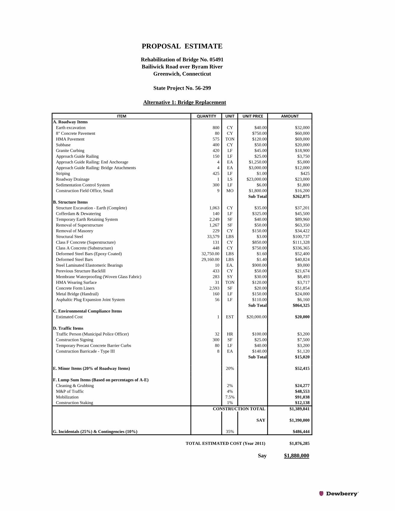
The proposed bridge replacement (year 2011 pricing) is estimated to cost $1,390,000 excluding costs associated with incidentals and contingencies (see Appendix E). The construction cost is estimated to be $1,880,000 if 35% is assumed as costs for incidentals and contingencies. 3.1.4 BENEFITS
The bridge replacement alternative will provide the following benefits:
a) Increase in hydraulic opening will minimize overtopping events especially during the lower frequency storms.
b) The presence of a rigid concrete pavement at the roadway approaches and a new stronger bridge will ensure that the bridge can be quickly reopened to vehicular traffic subsequent to overtopping events from higher frequency storms.
c) A bridge structure that does not encroach into the channel resulting in reduced scour depths and which would be looked upon favorably by the permitting agencies.

Structure Type Study
Rehabilitation of Bridge No. 05491
Bailiwick Road over Byram River
Greenwich, Connecticut
6
d) A new bridge with a service life of 50-75 years. e) Weathering steel beams are likely to be maintenance free during its service life without a
need for field painting. f) Conduits can be installed for future utility crossings between the beams providing an
opportunity to the Town.
3.2 ALTERNATIVE 2: BRIDGE REHABILITATION WITH ADDITION OF RELIEF
CULVERTS
3.2.1 DESIGN
In order to improve the hydraulic opening at the site while maintaining the existing bridge, installation of two (2) 9-foot wide by 4-foot high concrete box culverts located west of the existing bridge was considered. A hydraulics analysis indicates that the addition of relief culverts will reduce the upstream water surface elevations by approximately 2.3 inches and 1.3 inches from a 2-yr and the 10-yr storm event respectively. In this alternative, the existing arch bridge was studied for rehabilitation with the aim that it could be reopened quickly subsequent to a major overtopping event. In order to verify that the existing bridge had adequate capacity, a structural analysis of the arch was performed utilizing the Bentley computer program STAAD to determine the dead and live load forces. The dead loads acting on the arch include its own self weight and the weight of the proposed backfill, pavement and parapets and the lateral earth pressure resulting from the soil present behind the arches. The arch was modeled in STAAD utilizing beam elements since they are subjected to both axial forces and bending moments. The AASHTO HL-93 live load was modeled as a moving load and simulated to run on a fictitious roadway from the west (left) end to the east (right) end of the bridge model. A 3’-6” soil surcharge was used to model the load cases when an axle of the 28 foot long HL-93 truck was outside the bridge on the roadway approach.
The arch section properties were calculated and column interaction diagrams were developed for combined axial loads and bending moments using Excel spread sheets. Since the material properties of the existing concrete and reinforcing steel are not provided on the Original Construction Plans, a compressive strength of 2,500 psi for arch concrete and a yield stress of 40 ksi for reinforcing steel were assumed in accordance with the AASHTO Manual for Bridge Evaluation. The dead and live loads obtained from the STAAD analysis were combined to obtain the inventory ratings for the arch, utilizing the aforementioned interaction diagrams, at the support, crown and ¼ point locations. The governing Inventory Rating Factor of the arch was calculated to be 1.24 at the abutment indicating that the existing bridge has adequate capacity to support future loads. In Alternative 2, the existing flexible bituminous concrete pavement and fill material present above the arch will be removed to repair any concrete deterioration present on the arch extrados.
Structure Type Study
Rehabilitation of Bridge No. 05491
Bailiwick Road over Byram River
Greenwich, Connecticut
7
The concrete deterioration in the arch intrados will be repaired from the underside utilizing shielding and work platforms. Subsequent to the arch repairs, the stone masonry spandrel walls will be replaced with a concrete wall that will be attached to the arch to prevent its failure prior to backfilling the arch with granular fill. A moment slab will be installed to resist vehicular traffic impact loads from the parapet in order to meet current safety standards. An 8” thick rigid concrete pavement will be installed both on the bridge and the roadway approaches to prevent its washout during potential storm overtopping events. This alternative will also require the roadway at the bridge to be raised by 14 inches. The existing stone masonry wingwalls will be removed in their entirety and replaced with reinforced concrete wingwalls that will be extended to the headwall of the proposed culverts at the west approach. In order to provide for improved aesthetics and an appearance that is uniform and similar to the existing bridge, masonry facing will be provided on all exposed concrete surfaces. Similar to Alternative 1, the bridge rail system will consist of 2’-8” high concrete parapets and a single aluminum rail anodized to color brown. Box beam type weathering steel approach guiderails painted to color brown is proposed to protect traffic at the roadway approaches beyond the limits of the bridge. As mentioned previously, the bridge and approach guide rail system can be changed during the final design phase of the project depending upon the needs of the Town and input from the resident community. The general-plan, elevation and cross section of the proposed bridge configuration is depicted in Sketch 3 (Appendix C) and the computations of the arch analysis are attached as Appendix G. 3.2.2 CONSTRUCTABILITY Similar to Alternative 1, the existing bridge will be closed and the vehicular traffic detoured via the private roadway belonging to the Bailiwick Club to accomplish the construction. The arch extrados will be repaired subsequent to the removal of the existing pavement and fill material and the concrete deterioration in the arch intrados will be repaired from the underside utilizing shielding and work platforms. A concrete spandrel wall along with moment slab will be constructed at the fascias and the arch will be backfilled. Subsequent to the installation of cofferdams and temporary earth retaining systems, existing wingwalls will be removed, new relief culverts installed followed by the construction of new wingwalls and headwalls. The bridge will be reopened to vehicular traffic after completion of the approach roadway work including the installation of an 8” thick rigid concrete pavement. The construction duration is estimated to be approximately 7 months (See Appendix D) similar to Alternative 1.
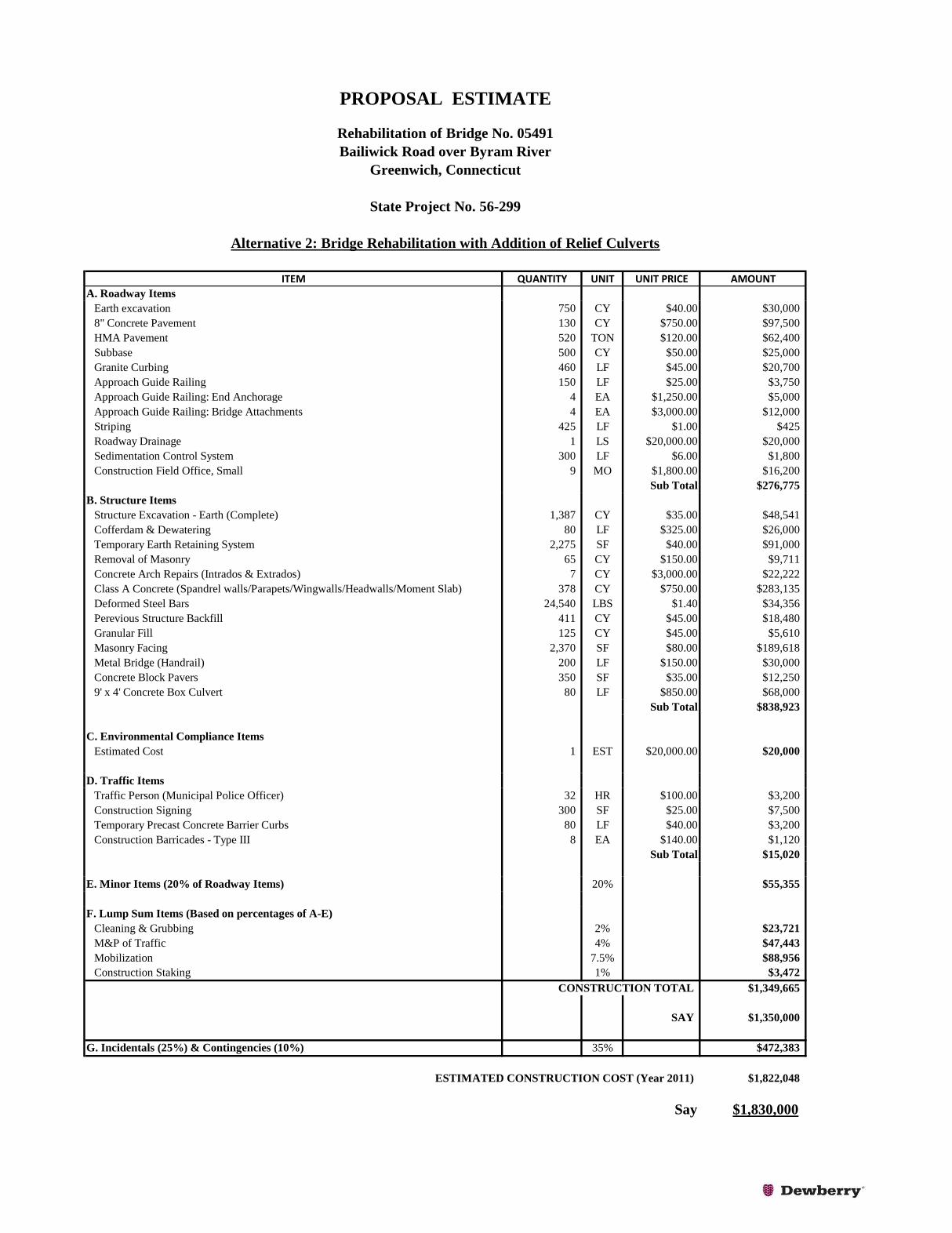
3.2.3 COST ESTIMATE The proposed bridge rehabilitation (year 2011 pricing) is estimated to cost $1,350,000 excluding costs associated with incidentals and contingencies (see Appendix E). The construction cost is estimated to be $1,830,000 if 35% is assumed as costs for incidentals and contingencies.

Structure Type Study
Rehabilitation of Bridge No. 05491
Bailiwick Road over Byram River
Greenwich, Connecticut
8
3.2.4 BENEFITS
The bridge rehabilitation alternative will provide the following benefits:
a) Slight improvement in hydraulic opening will result in some reduction of overtopping events especially during the lower frequency storms.
b) The presence of a rigid reinforced concrete pavement and spandrel walls positively attached to the arch will ensure that the bridge can be quickly reopened to vehicular traffic subsequent to overtopping events from the higher frequency storms.
c) A rehabilitated bridge with a service life of 30-40 years. d) While conduits can be installed above the arch for future utility crossings, their size will
be limited by the fill depth and cover requirements.
The main drawbacks with this alternative are the smaller increase in the hydraulic opening and the addition of culverts to the Town’s bridge inventory requiring their long term maintenance.
4. SUMMARY, CONCLUSIONS & RECOMMENDATIONS
The goals of the project are to improve the hydraulic capacity of the bridge and to ensure that the Bailiwick Road Bridge and the approach roadways can be reopened quickly to vehicular traffic subsequent to major storm events so that the community comprising of approximately 200 residents do not feel stranded as this bridge provides their only official access for ingress and egress. Based on a preliminary hydraulic analysis performed by Dewberry, the following alternatives were proposed for investigation in the Structure Type Study:
1. Alternative 1 – Bridge replacement 2. Alternative 2 – Bridge rehabilitation with addition of relief culverts 3. Alternative 3 – Bridge rehabilitation with lowering of west approach roadway
Based on the preliminary hydraulic analysis, a new multi-girder single span bridge with a 50-foot opening was determined to provide the maximum hydraulic benefits due to reductions of approximately 5.3 inches and 3 inches in the upstream water surface elevations from a 2-yr and a 10-yr storm event respectively. It was determined that the installation of two (2) 9-foot wide by 4-foot high concrete relief culverts installed west of the existing bridge would reduce the upstream water surface elevations by approximately 2.3 inches and 1.3 inches for the 2-yr and the 10-yr storm event respectively. It was determined that there were no benefits or reductions in the upstream water surface elevations by simply lowering the west approach roadway and therefore Alternative 3 was not further investigated in this study. A geotechnical investigation comprising of three soil borings was initiated to obtain information about the soil conditions in order to determine the existing/proposed foundation capacities, verify the ability of the foundations to withstand design scour conditions and help in determining the need for any countermeasures. The presence of shallow bedrock elevations indicates that shallow spread footings founded on bedrock will be adequate to support the proposed bridge structure

Structure Type Study
Rehabilitation of Bridge No. 05491
Bailiwick Road over Byram River
Greenwich, Connecticut
9
and that scour will not be a challenge. The results of the geotechnical investigations will be submitted separately to the Town/ConnDOT as an independent Foundations Report.
In Alternative 1, the existing concrete arch, footings and the wingwalls will be removed in their entirety. New concrete abutments and wingwalls supported by spread footings founded on bedrock will be constructed to support a new 53’-0” long bridge with a reinforced concrete deck made composite with maintenance free weathering steel rolled beams to provide for a 50’-0” wide hydraulic opening. A rigid concrete pavement will be utilized to construct the roadway approaches to eliminate pavement washouts during storm events and to facilitate a quicker reopening of the bridge subsequent to overtopping events. Form liners will be used on all exposed concrete surfaces to provide an appearance of stone masonry for improved aesthetics. In Alternative 2, the existing arch bridge was studied for rehabilitation with the aim that it could be reopened quickly subsequent to a major overtopping event. A structural analysis of the arch indicates that the bridge has adequate capacity to support future loads. In this alternative, the existing bituminous concrete pavement and backfill material present above the arch will be removed prior to repairing potential concrete deterioration present on the arch intrados and extrados. The stone masonry spandrel walls will be replaced with a concrete wall positively attached to the arch to prevent its failure. A moment slab will be installed to resist vehicular traffic impact loads from the parapet in order to meet current safety standards and an 8” thick rigid concrete pavement will be installed both on the bridge and the roadway approaches to prevent its washout during potential storm events. The existing stone masonry wingwalls will be removed in its entirety and replaced with reinforced concrete wingwalls that will be extended to the headwall of the proposed relief culverts to be installed west of the existing bridge. In order to provide for improved aesthetics and an appearance that is uniform, consistent and similar to the existing bridge, masonry facing will be provided on all exposed concrete surfaces.
The bridge rail system in both the alternatives will consist of a 2’-8” high concrete parapet and a single aluminum rail anodized to color brown. This rail system was utilized in the hydraulics model since it is believed that even though the use of an alternative open bridge rail system would result in additional hydraulics benefits (i.e. further reductions in upstream water surface elevations), the permitting process would likely be more challenging without a prior evaluation of impacts downstream of the bridge site. The Town may consider further investigating this option in the Final Design Phase of the project. Box beam type weathering steel approach guiderails painted to color brown is proposed to protect traffic at the roadway approaches beyond the limits of the bridge. The type and color of the proposed bridge and the approach guide rail system can be changed during the final design phase of the project based on the needs of the Town and input from the resident community. Cofferdams and temporary earth retaining systems will be required in both the alternatives in order to excavate and remove the existing structure and to accomplish the proposed construction in the dry. A debris shield will be installed below the arch prior to demolishing the existing bridge (Alternative 1) or performing arch repairs (Alternative 2) in order to prevent any debris from falling into the river. In both the alternatives, the bridge will be closed and the vehicular

Structure Type Study
Rehabilitation of Bridge No. 05491
Bailiwick Road over Byram River
Greenwich, Connecticut
10
traffic detoured via the private roadway belonging to the Bailiwick Club during construction. The construction duration for both the alternatives is estimated to be approximately 7 months.
The proposed replacement/rehabilitation is estimated to cost $1,880,000 and $1,830,000 for Alternatives 1 and 2 respectively assuming 25% and 10% for incidental and contingency costs respectively.
Even though the bridge replacement alternative is estimated to be slightly more expensive, improvement in hydraulic opening and minimizing potential overtopping during the lower frequency storm events, a bridge structure not encroaching into the channel aiding the permitting approval process and a new stronger bridge with a rigid concrete pavement that will not washout and ensure that the bridge and the roadway can be quickly reopened to vehicular traffic subsequent to storm events are some of the main benefits with this alternative. Other benefits with this alternative include a new bridge with a service life of 50-75 years, maintenance free nature of weathering steel beams and the feasibility of installing conduits for future utility crossings. For nearly the same cost as Alternative 1, the bridge rehabilitation alternative will provide for a somewhat lesser hydraulics improvement; however a rehabilitated bridge with a service life of 30-40 years and the presence of a rigid reinforced concrete pavement and a spandrel wall positively attached to the arch will ensure that the bridge can be quickly reopened to vehicular traffic subsequent to overtopping events. The Town will be required to maintain an additional bridge comprising of the two relief culverts. Based on the benefits, cost estimate and duration of construction, we recommend the selection of Alternative 1 with the construction of a new bridge. It is also recommended that the Town investigate the feasibility of further improving the hydraulics by conducting a downstream impact analysis.

Structure Type Study
Rehabilitation of Bridge No. 05491
Bailiwick Road over Byram River
Greenwich, Connecticut
Appendix A
Location Map

Location Map
Bridge 05491
Byram River
Aerial View of Project Site
Bridge 05491
Bailiwick Club
Private Road/
Potential Detour

Structure Type Study
Rehabilitation of Bridge No. 05491
Bailiwick Road over Byram River
Greenwich, Connecticut
Appendix B
Photos
59 Elm Street, Suite 101
New Haven, CT 06510
STRUCTURE TYPE STUDY
BRIDGE NO. 05491,BAILIWICK ROAD OVER BYRAM RIVER
GREENWICH, CT
Photo Sheet
1 of 3
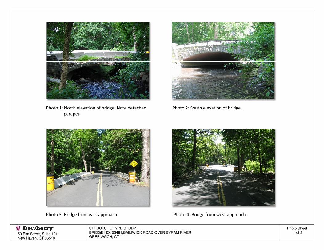
Photo 1: North elevation of bridge. Note detached Photo 2: South elevation of bridge.
parapet.
Photo 3: Bridge from east approach. Photo 4: Bridge from west approach.

59 Elm Street, Suite 101
New Haven, CT 06510
STRUCTURE TYPE STUDY
BRIDGE NO. 05491,BAILIWICK ROAD OVER BYRAM RIVER
GREENWICH, CT
Photo Sheet
2 of 3
Photo 5: Remnants of rubble stone masonry spandrel Photo 6: Existing bridge rail system at south fascia.
wall/parapet at north fascia.
Photo 7: Condition of arch underside (west half). Photo 8: Condition of arch underside (east half).

59 Elm Street, Suite 101
New Haven, CT 06510
STRUCTURE TYPE STUDY
BRIDGE NO. 05491,BAILIWICK ROAD OVER BYRAM RIVER
GREENWICH, CT
Photo Sheet
3 of 3
Photo 9: Condition of NE stone masonry wingwall. Photo 10: Missing stones in wingwall parapet.

Structure Type Study
Rehabilitation of Bridge No. 05491
Bailiwick Road over Byram River
Greenwich, Connecticut
Appendix C
Sketches

1 in.
TW 10/16 i
n.
Q 8 in.
4 in. 8 in.
3 in.
3 in.
36 in.
2 in.
2 in.
2 in.
2 in.
2 in.
2 in.
4 in.
3 in.1 in.
32 in.
6x1 in.
TW 5 in.
8 in.
80134
CL&P
8134A
CL&P
WF 46
WF 47WF 30
WF 31
WF 26WF 1
NO OUTLETSIGNNO PARK
SIGN
AT&TUGUF
CATVUGUF
CL&PUGUF
BIT. L.O.
BIT. L.O.
JPG-3 (I. P
IN)
No. 05491
BRIDGE
AQUARION W
ATER CO.
EXPOSED WATER M
AIN
- -
-
-
-
- -
- - -
- - - -
- - -
- - -
- - - -
REHABILITATION OF BRIDGE
NO. 05491 BAILIWICK ROAD
OVER BYRAM RIVER
GREENWICH 56-299
{ BAILIWICK ROAD
36’-6"|
VA
RIES
SCALE: �" = 1’-0"
SCALE: 1" = 10’
GENERAL PLAN AND
CROSS SECTION
38’-0"|
VARIES)
ARCH SLAB (THICKNESS
(THICKNESS VARIES)
GRANULAR FILL
(TYP.)
SPANDREL WALL/PARAPET
STONE MASONRY4"| ASPHALT PAVEMENT
P.A.G.
(T
YP.)
6"
(TYP.)
FACING
MASONRY
15’-0"|PAVEMENT
EDGE OF
PAVEMENT
EDGE OF
WINGWALL 1A
WINGWALL 1B
GRASS WALKWAY
ARCH BRIDGE
EXIST. CONCRETE
GENERAL PLANSCALE: 1" = 10’
RIVER
BYRAM
WINGWALL 2B
APPROX. { BAILIWICK ROAD
COMPANY)
(AQUARION WATER
EXISTING WATER MAIN
WINGWALL 2A
SOUTH ELEVATION
(TYP.)
EL. 120.6|
33’-8�"
(ELEVATION VARIES)
WATERLINE
ORDINARY HIGH 4"X4" STEEL TUBE RAIL
MASONRY WINGWALL (TYP.)
CEMENT RUBBLE STONE
(TYP.)
EL. 127.4|
EL. 130.8|
EXIST. ROADWAY
T.STRNAD/S.ERDAS
A. SESHADRI
1ELEVATION-EXISTING BRIDGE
EXIST. GRADE
30’-0"
(SURVEY)
CHANNEL BED
APPROX. EXIST.
TUBE RAIL (TYP.)
4"X4" STEEL
1’-6"|
LANE
15’-0"|
LANE
15’-0"|
GRASS WALKWAY
5’-0"| 1’-6"|
ROAD
} BAILIWICK
WALL
FACE OF WALL
FACE OF
1’-6"|
5’-0"|
15’-0"|
1’-6"|
FACING
WITH MASONRY
CONCRETE ARCH
STRUCTURE STUDY REPORT
DESIGNER/DRAFTER:
CHECKED BY:
PROJECT TITLE: TOWN:
DRAWING TITLE:
PROJECT NO.
DRAWING NO.
SKETCH NO.
Filename:SHEET NO.REVISION DESCRIPTIONDATEREV.
DEPARTMENT OF PUBLIC WORKS
TOWN OF GREENWICH
SCALE AS NOTED
10/6/2011
BLOCK:
SIGNATURE/
DATE: APPROVED BY:
Dewberry-Goodkind, Inc.
...\SB_MSH_056_0299_GPN-EXIST.dgnPlotted Date:
E 748231.49
N 578938.37
STA 105+41.46
PC
106+00
105+00
1 in.
TW 10/16 i
n.
Q 8 in.
4 in. 8 in.
3 in.
3 in.
36 in.
2 in.
2 in.
2 in.
2 in.
2 in.
2 in.
4 in.
3 in.1 in.
32 in.
6x1 in.
TW 5 in.
8 in.
80134
CL&P
8134A
CL&P
WF 46
WF 47WF 30
WF 31
WF 26WF 1
NO OUTLETSIGNNO PARK
SIGN
AT&TUGUF
CATVUGUF
CL&PUGUF
BIT. L.O.
BIT. L.O.
JPG-3 (I. P
IN)
No. 05491
BRIDGE
AQUARION W
ATER CO.
EXPOSED WATER M
AIN

Q 8 in.
8 in.
4 in. 8 in.
3 in.
3 in.
36 in.
2 in.
2 in.
2 in.
2 in.
2 in.
2 in.12 in
.
4 in.
3 in.1 in.
32 in.
6x1 in.
TW 5 in.
8 in.
80134
CL&P
8134A
CL&P
WF 46
WF 47WF 30
WF 31
WF 26WF 1
NO OUTLETSIGNNO PARK
SIGN
AT&TUGUF
BIT. L.O.
BIT. L.O.
JPG-3 (I. P
IN)
No. 05491
BRIDGE
AQUARION W
ATER CO.
EXPOSED WATER M
AIN
130
E 748231.49
N 578938.37
STA 105+41.46
PC
106+00
105+00
- -
-
-
-
- -
- - -
- - - -
- - -
- - -
- - - -
REHABILITATION OF BRIDGE
NO. 05491 BAILIWICK ROAD
OVER BYRAM RIVER
GREENWICH 56-299
GENERAL PLAN AND
STA 105+30.50
BEGIN BRIDGE
SKEW (TYP.)
22°56’ 45.09"
WINGWALL (TYP.)
REMOVE EXISTING
WINGWALL 1A
N 78°50’ 18.16 E
WINGWALL 1B
14’-0"
14’-0"
1’-10"
ABUTMENT
FACE OF
CURB LINE
LINE
CHORD
FACE OF ABUTMENT
WINGWALL 2B
WINGWALL 2A
ABUTMENT 1
BEARINGS
{ EXPANSION
ABUTMENT 2
{ FIXED BEARINGS,
SHOULDER
3’-0"
LANE
11’-0"
LANE
11’-0"
SHOULDER
3’-0"
1’-10"
1’-10"
B4B3B2B1 B5
(WOVEN GLASS FABRIC)
MEMBRANE WATERPROOFING
1" HMA S0.375 ON
2" HMA S0.5 ON
P.A.G.
�" / FT�" / FT
SLAB
8�" CONCRETE
} BAILIWICK ROAD
4 SPACES @ 6’-9" = 27’-0"
CROSS SECTIONSCALE: �" = 1’-0"
T.STRNAD/S.ERDAS
A. SESHADRI
GENERAL PLANSCALE: 1" = 10’
(VARIES)
2’-1�" TO 2’-8"
(VARIES)
4�" MAX.
RIVER
BYRAM
SH
LD
3’-0"
LA
NE
11’-0"
LA
NE
11’-0"
SH
LD
3’-0"
RA
DIA
L
1’-10"
(TYP.)
PAINTED TO COLOR BROWN
GALVANIZED & SHOP
BOX BEAM GUIDE RAIL,
} BAILIWICK ROAD
31’-8" TO 32’-4�"
INTERMEDIATE DIAPHRAGM (TYP.)
C12 x 20.7
LINE
CURB
1’-11�" TO 2’-7�"
(VARIES)
CONSTRUCTION
PROTECTED DURING
COMPANY) TO BE
(AQUARION WATER
EXISTING WATER MAIN
STA 105+89.60
END BRIDGE
STA 105+86.53
W.P. 2
STA 105+33.50
W.P. 1,
BRIDGE & FOOTINGS
CONCRETE ARCH
REMOVE EXISTING
(TYP.)
PAINTED TO COLOR BROWN
GALVANIZED & SHOP
BOX BEAM GUIDE RAIL,
(TYP.)
PROPOSED GRADE
SCALE: 1" = 10’
SOUTH ELEVATION
ABUTMENT 1
{ EXPANSION BEARINGS,
(ELEVATION VARIES)
ORDINARY HIGH WATERLINE
EL. TBD (TYP.)
BOTTOM OF FOOTING,
ABUTMENT 2
{ FIXED BEARINGS,53’-0"
ARCH BRIDGE & FOOTINGS
REMOVE EXIST. CONCRETE
(TYP.)
EL. 120.6|
ELEVATION-ALTERNATIVE 1
BEAM (TYP.)
WEATHERING STEEL
W21 X 101
TO COLOR BROWN (TYP.)
(HANDRAIL) ANODIZED
METAL BRIDGE RAIL
FORM LINERS (TYP.)
TREATMENT UTILIZING
WITH ARCHITECTURAL
2’-8" HIGH PARAPET& { BEAM B3
CHORD LINE
1’-3" APPROACH SLAB (TYP.)
3" HMA PAVEMENT OVER
CONCRETE DECK
BRIDGE WITH COMPOSITE
PROPOSED WEATHERING STEEL
(TYP.) (BY CL&P)
TO BE RELOCATED
EXIST. UTILITY POLE
8" CONCRETE PAVEMENT
2" HMA PAVEMENT OVER
EL. 130.82
LOW CHORD
CONCRETE DECK
BRIDGE WITH COMPOSITE
PROPOSED WEATHERING STEEL
EL. 130.8|
CHANNEL BED (SURVEY)
APPROX. EXIST.
UTILIZING FORMLINERS
ARCHITECTURAL TREATMENT
JOINT
1" EXPANSION
2
(T
YP.)
2’-8"
RECONSTRUCTION
FULL DEPTH HMA PAVEMENT
COLOR BROWN
ANODIZED TO
(HANDRAIL)
METAL BRIDGE RAIL
(TYP.)
ROADWAY
PROPOSED
ANODIZED TO COLOR BROWN
METAL BRIDGE RAIL (HANDRAIL)
GRANITE CURB
BORING B1)
EL. 124.1 (BASED ON
APPROX. TOP OF ROCK,
BORING B2)
EL. 123.5 (BASED ON
APPROX. TOP OF ROCK,
BORING B3)
EL. 121.4 (BASED ON
APPROX. TOP OF ROCK,
BORING LOCATION
DIRECTION OF TRAFFIC
LEGEND
B1
B2
B3
STRUCTURE TYPE STUDY
DESIGNER/DRAFTER:
CHECKED BY:
PROJECT TITLE: TOWN:
DRAWING TITLE:
PROJECT NO.
DRAWING NO.
SKETCH NO.
Filename:SHEET NO.REVISION DESCRIPTIONDATEREV.
DEPARTMENT OF PUBLIC WORKS
TOWN OF GREENWICH
SCALE AS NOTED
10/6/2011
BLOCK:
SIGNATURE/
DATE: APPROVED BY:
Dewberry-Goodkind, Inc.
...\SB_MSH_056_0299_GPN-ALT1.dgnPlotted Date:

- -
-
-
-
- -
- - -
- - - -
- - -
- - -
- - - -
REHABILITATION OF BRIDGE
NO. 05491 BAILIWICK ROAD
OVER BYRAM RIVER
GREENWICH 56-299
} BAILIWICK ROAD
36’-6"|
SCALE: �" = 1’-0"
SCALE: 1" = 10’
GENERAL PLAN ANDELEVATION-ALTERNATIVE 2
T.STRNAD/S.ERDAS
A.SESHADRI
38’-0"|
9"
3"
LANE
11’-0"
LANE
11’-0"
�"/FT �"/FT
3"
1’-6" 9"
(TYP.)
REINFORCEMENT
DRILL AND GROUT
(TYP.)
FACING
MASONRY
(TYP.)
WALL
SPANDREL
P.A.G.
ROAD
} BAILIWICK
HEADWALL 1
WINGWALL 3A
2’-6"
LINE
CURB
LINE
CURB
HEADWALL 2
WINGWALL 3BTO COLOR BROWN (TYP.)
GALVANIZED & SHOP PAINTED
BOX BEAM GUIDE RAIL,
RIVER
BYRAM
SCALE: 1" = 10’
GENERAL PLAN
WINGWALL 1B
20’-9�"
33’-8�"
WINGWALL 2B
15’-11"
SPANDREL WALL (ELEVATION VARIES)
WATERLINE
ORDINARY HIGH
EL. TBD (TYP.)
BOTTOM OF FOOTING,
PROPOSED GRADE
(TYP.)
EL. 120.61
SOUTH ELEVATION
PROPOSED ROADWAY
(TYP.)
STANDARD RIPRAPEL. TBD
CUT-OFF WALL
(TYP.)
MASONRY FACING
TO COLOR BROWN (TYP.)
GALVANIZED & SHOP PAINTED
BOX BEAM GUIDE RAIL,
(VARIES)
3’-0" MIN.
SHLD
3’-0"7"
CURBING
8"X16" SLOPED GRANITE
SLAB (TYP.)
1’-0" MOMENT
(THICKNESS VARIES)
GRANULAR FILL
CROSS SECTION
& EXTRADOS
ARCH INTRADOS
REPAIR EXISTING
(TYP.)
ANODIZED TO COLOR BROWN
METAL BRIDGE RAIL (HANDRAIL)
CURBING
6" GRANITE
PAVEMENT
8" CONCRETE
VARIES)
ARCH SLAB (THICKNESS
WINGWALL 1B
WINGWALL 1AWINGWALL 2A
GRANITE CURBING
8"X16" SLOPED
WINGWALL 2B
RA
DIA
L
14’-0"
CURBING
6" GRANITE
(BY CL&P) (TYP.)
TO BE RELOCATED
EXIST. UTILITY POLE
OVER FLOW
TO COLOR BROWN
(HANDRAIL) ANODIZED
METAL BRIDGE RAIL
HEADWALL 2
21’-8"
TO COLOR BROWN
(HANDRAIL) ANODIZED
METAL BRIDGE RAIL
CHANNEL BED (SURVEY)
APPROX. EXIST.
ARCH INTRADOS & EXTRADOS
REPAIR EXISTING
(TYP.)
EL. 127.4|
EL. 130.8|
CONSTRUCTION
PROTECTED DURING
COMPANY) TO BE
(AQUARION WATER
EXISTING WATER MAIN
3
PAVERS (TYP.)
3" CONCRETE BLOCK
2’-8"
SHLD
3’-0" MIN.
2’-8"
RA
DIA
L
11’-0"
RA
DIA
L
11’-0"
2’-3"
MIN.
14’-0"
B1
B2
B3
SH
LD
3’-0"
SH
LD
3’-0"
MIN.
BL
OC
K
PA
VE
RS
3’-0"
MIN.
CO
NC
RE
TE
(TYP.)
WITH CONCRETE WINGWALLS
WINGWALLS & REPLACE
REMOVE EXISTING MASONRY
PAVEMENT
MOMENT SLAB & INSTALL CONCRETE
REPLACE SPANDREL WALL, CONSTRUCT
& REPAIR ARCH INTRADOS & EXTRADOS.
REMOVE FILL ABOVE EXISTING ARCH
ARCH BRIDGE NO. 05491
EXISTING CONCRETE
PAVEMENT
LIMITS OF 8" CONCRETE
104+00
TO STA.
BORING B1)
EL. 124.1 (BASED ON
APPROX. TOP OF ROCK,
BORING B2)
EL. 123.5 (BASED ON
APPROX. TOP OF ROCK,
BORING B3)
EL. 121.4 (BASED ON
APPROX. TOP OF ROCK,
INV. EL. 126.9
RELIEF CULVERTS
(2)-9’-0" X 4’-0" CONC.
BORING LOCATION
DIRECTION OF TRAFFIC
LEGEND
STRUCTURE STUDY REPORT
DESIGNER/DRAFTER:
CHECKED BY:
PROJECT TITLE: TOWN:
DRAWING TITLE:
PROJECT NO.
DRAWING NO.
SKETCH NO.
Filename:SHEET NO.REVISION DESCRIPTIONDATEREV.
DEPARTMENT OF PUBLIC WORKS
TOWN OF GREENWICH
SCALE AS NOTED
10/6/2011
BLOCK:
SIGNATURE/
DATE: APPROVED BY:
Dewberry-Goodkind, Inc.
...\SB_MSH_056_0299_GPN-ALT2.dgnPlotted Date:
CULVERTS. BRIDGE NO. TBD
(2) 9’-0" X 4’-0" CONCRETE RELIEF
1’-6"
E 748231.49
N 578938.37
STA 105+41.46
PC
106+00
105+00
1301 in.
TW 10/16 i
n.
Q 8 in.
4 in. 8 in.
3 in.
3 in.
36 in.
2 in.
2 in.
2 in.
2 in.
2 in.
2 in.
4 in.
3 in.1 in.
32 in.
6x1 in.
TW 5 in.
8 in.
80134
CL&P
8134A
CL&P
WF 46
WF 47WF 30
WF 31
WF 26WF 1
NO OUTLETSIGNNO PARK
SIGN
AT&TUGUF
CATVUGUF
CL&PUGUF
BIT. L.O.
BIT. L.O.
JPG-3 (I. P
IN)
No. 05491
BRIDGE
AQUARION W
ATER CO.
EXPOSED WATER M
AIN

Structure Type Study
Rehabilitation of Bridge No. 05491
Bailiwick Road over Byram River
Greenwich, Connecticut
Appendix D
Construction
Schedule

OPERATION DATE
Advertisement 1/1/2014
Bid opening 2/1/2014
Award contract 3/15/2014
Notice to proceed 4/1/2014
Mobilization 4/1/2014
Install detour plan & close bridge to through traffic 4/15/2014
Temporary/permanent utility relocation
Clearing & grubbing & install sed. control system
Install debris shield, excavate & remove existing arch bridge
Install temporary earth retaining system
Complete structure excavation
Remove existing arch bridge footings & wingwalls
Construct abutment & wingwall footings
Construct abutment and wingwall stems
Backfill behind abutments & wingwalls and remove
temporary earth retaining system
Install bearings and erect steel beams
Construct bridge deck & parapets
Construct approach slabs
Install waterproofing membrane & bituminous wearing
surface on bridge deck/approach slab
Complete earth excavation & install concrete pavement at
roadway approaches
Complete drainage and approach roadway work
Install bridge rail and approach guiderails
Loam & seed disturbed areas
Open bridge to thru traffic 10/31/2014
0 30 60 90 120 150 180 210
September
CONSTRUCTION SCHEDULE
REHABILITATION OF BRIDGE NO. 05491
TOWN OF GREENWICH, CT
STATE PROJECT No. 56-299
ALTERNATIVE 1: BRIDGE REPLACEMENT
October November
BAILIWICK ROAD OVER BYRAM RIVER
December
2014
January February March April May June July August

OPERATION DATE
Advertisement 1/1/2014
Bid opening 2/1/2014
Award contract 3/15/2014
Notice to proceed 4/1/2014
Mobilization 4/1/2014
Install detour plan & close bridge to through traffic 4/15/2014
Temporary/permanent utility relocation
Clearing & grubbing & install sed. control system
Install work platforms below existing arch bridge & remove
fill material above the arch
Perform repairs to existing arch intrados/extrados
Install temporary earth retaining system
Complete structure excavation
Remove existing wingwalls
Install new box culverts
Construct new wingwall footings
Construct culvert headwalls, wingwall stems & spandrel walls
Install moment slab over arch bridge
Backfill behind/above wingwalls, culverts & existing arch
bridge
Install masonry facing
Complete earth excavation & install concrete pavement
Complete drainage and approach roadway work
Install bridge rail and approach guiderails
Loam & seed disturbed areas
Open bridge to thru traffic 10/31/2014
0 30 60 90 120 150 180 210
September October November December
ALTERNATIVE 2: BRIDGE REHABILITATION WITH ADDITION OF RELIEF CULVERTS
2014
January February March April May June July August
CONSTRUCTION SCHEDULE
REHABILITATION OF BRIDGE NO. 05491
BAILIWICK ROAD OVER BYRAM RIVER
TOWN OF GREENWICH, CT
STATE PROJECT No. 56-299

Structure Type Study
Rehabilitation of Bridge No. 05491
Bailiwick Road over Byram River
Greenwich, Connecticut
Appendix E
Cost Estimates
ITEM QUANTITY UNIT UNIT PRICE AMOUNT
A. Roadway Items
Earth excavation 800 CY $40.00 $32,000
8" Concrete Pavement 80 CY $750.00 $60,000
HMA Pavement 575 TON $120.00 $69,000
Subbase 400 CY $50.00 $20,000
Granite Curbing 420 LF $45.00 $18,900
Approach Guide Railing 150 LF $25.00 $3,750
Approach Guide Railing: End Anchorage 4 EA $1,250.00 $5,000
Approach Guide Railing: Bridge Attachments 4 EA $3,000.00 $12,000
Striping 425 LF $1.00 $425
Roadway Drainage 1 LS $23,000.00 $23,000
Sedimentation Control System 300 LF $6.00 $1,800
Construction Field Office, Small 9 MO $1,800.00 $16,200
Sub Total $262,075
B. Structure Items
Structure Excavation - Earth (Complete) 1,063 CY $35.00 $37,201
Cofferdam & Dewatering 140 LF $325.00 $45,500
Temporary Earth Retaining System 2,249 SF $40.00 $89,960
Removal of Superstructure 1,267 SF $50.00 $63,350
Removal of Masonry 229 CY $150.00 $34,422
Structural Steel 33,579 LBS $3.00 $100,737
Class F Concrete (Superstructure) 131 CY $850.00 $111,328
Class A Concrete (Substructure) 448 CY $750.00 $336,365
Deformed Steel Bars (Epoxy Coated) 32,750.00 LBS $1.60 $52,400
Deformed Steel Bars 29,160.00 LBS $1.40 $40,824
Steel Laminated Elastomeric Bearings 10 EA. $900.00 $9,000
Perevious Structure Backfill 433 CY $50.00 $21,674
Membrane Waterproofing (Woven Glass Fabric) 283 SY $30.00 $8,493
HMA Wearing Surface 31 TON $120.00 $3,717
Concrete Form Liners 2,593 SF $20.00 $51,854
Metal Bridge (Handrail) 160 LF $150.00 $24,000
Asphaltic Plug Expansion Joint System 56 LF $110.00 $6,160
Sub Total $864,325
C. Environmental Compliance Items
Estimated Cost 1 EST $20,000.00 $20,000
D. Traffic Items
Traffic Person (Municipal Police Officer) 32 HR $100.00 $3,200
Construction Signing 300 SF $25.00 $7,500
Temporary Precast Concrete Barrier Curbs 80 LF $40.00 $3,200
Construction Barricade - Type III 8 EA $140.00 $1,120
Sub Total $15,020
E. Minor Items (20% of Roadway Items) 20% $52,415
F. Lump Sum Items (Based on percentages of A-E)
Cleaning & Grubbing 2% $24,277
M&P of Traffic 4% $48,553
Mobilization 7.5% $91,038
Construction Staking 1% $12,138
CONSTRUCTION TOTAL $1,389,841
SAY $1,390,000
G. Incidentals (25%) & Contingencies (10%) 35% $486,444
TOTAL ESTIMATED COST (Year 2011) $1,876,285
Say $1,880,000
Alternative 1: Bridge Replacement
PROPOSAL ESTIMATE
Rehabilitation of Bridge No. 05491
Bailiwick Road over Byram River
Greenwich, Connecticut
State Project No. 56-299
ITEM QUANTITY UNIT UNIT PRICE AMOUNT
A. Roadway Items
Earth excavation 750 CY $40.00 $30,000
8" Concrete Pavement 130 CY $750.00 $97,500
HMA Pavement 520 TON $120.00 $62,400
Subbase 500 CY $50.00 $25,000
Granite Curbing 460 LF $45.00 $20,700
Approach Guide Railing 150 LF $25.00 $3,750
Approach Guide Railing: End Anchorage 4 EA $1,250.00 $5,000
Approach Guide Railing: Bridge Attachments 4 EA $3,000.00 $12,000
Striping 425 LF $1.00 $425
Roadway Drainage 1 LS $20,000.00 $20,000
Sedimentation Control System 300 LF $6.00 $1,800
Construction Field Office, Small 9 MO $1,800.00 $16,200
Sub Total $276,775
B. Structure Items
Structure Excavation - Earth (Complete) 1,387 CY $35.00 $48,541
Cofferdam & Dewatering 80 LF $325.00 $26,000
Temporary Earth Retaining System 2,275 SF $40.00 $91,000
Removal of Masonry 65 CY $150.00 $9,711
Concrete Arch Repairs (Intrados & Extrados) 7 CY $3,000.00 $22,222
Class A Concrete (Spandrel walls/Parapets/Wingwalls/Headwalls/Moment Slab) 378 CY $750.00 $283,135
Deformed Steel Bars 24,540 LBS $1.40 $34,356
Perevious Structure Backfill 411 CY $45.00 $18,480
Granular Fill 125 CY $45.00 $5,610
Masonry Facing 2,370 SF $80.00 $189,618
Metal Bridge (Handrail) 200 LF $150.00 $30,000
Concrete Block Pavers 350 SF $35.00 $12,250
9' x 4' Concrete Box Culvert 80 LF $850.00 $68,000
Sub Total $838,923
C. Environmental Compliance Items
Estimated Cost 1 EST $20,000.00 $20,000
D. Traffic Items
Traffic Person (Municipal Police Officer) 32 HR $100.00 $3,200
Construction Signing 300 SF $25.00 $7,500
Temporary Precast Concrete Barrier Curbs 80 LF $40.00 $3,200
Construction Barricades - Type III 8 EA $140.00 $1,120
Sub Total $15,020
E. Minor Items (20% of Roadway Items) 20% $55,355
F. Lump Sum Items (Based on percentages of A-E)
Cleaning & Grubbing 2% $23,721
M&P of Traffic 4% $47,443
Mobilization 7.5% $88,956
Construction Staking 1% $3,472
CONSTRUCTION TOTAL $1,349,665
SAY $1,350,000
G. Incidentals (25%) & Contingencies (10%) 35% $472,383
ESTIMATED CONSTRUCTION COST (Year 2011) $1,822,048
Say $1,830,000
State Project No. 56-299
Rehabilitation of Bridge No. 05491
Bailiwick Road over Byram River
PROPOSAL ESTIMATE
Greenwich, Connecticut
Alternative 2: Bridge Rehabilitation with Addition of Relief Culverts