static analysis of tube to header weld joint configurations · static analysis of tube to header...
TRANSCRIPT
Static Analysis of Tube to Header Weld Joint
Configurations
T. Shyju P G -Scholar,
Manufacturing Engineering
University College of Engineering, BIT campus
Trichy, Tamil Nadu, India
C . Saravanan Asst. Professor,
Dept. of Mechanical Engineering
University College of Engineering, BIT Campus
Trichy, Tamil Nadu, India
Dr. T. Senthil Kumar Dean,
University College of Engineering,
BIT Campus,
Trichy, Tamil Nadu, India
Dr. B. Kumaragurubaran Asst. Professor,
Dept. of Mechanical Engineering University College of Engineering, BIT Campus
Trichy, Tamil Nadu, India
Abstract— Failures in the tube to header joints causing leakages are
frequent source of outages in power plant arena. The pressure vessel
designer has to consider the subtle nuances in selecting the weld joint
configuration which suits the type of loading applications. Established
national and international Pressure vessel codes like ASME, IBR and
British standards have given certain guidelines to design the weld but the
take pressure forces only to account for. A designer has to envisage and
meticulously build in other loads like thermal, dead weight and cyclic
loads) as well. The workmanship also plays a major role in giving the
adequate strength to the weld. The weld configuration as such can be
broadly classified into Partial penetration or full strength welding and full
penetration welding. The paper discusses the behavior of the
aforementioned two configurations in three different types of load cases.
Keywords—Full penetration Weld, Full Strength weld, Partial Penetration
Weld,
I. INTRODUCTION
Welding forms a part of the most comprehensive process to fabricate pressure vessel shells. Structural members, pressure part, non-pressure parts such as lifting lugs, stiffening rings support cliffs for piping and internal trays are usually welded to the vessel wall. Welded joints are often preferred for a piping to vessel connection for a leak proof joint. Selection of inappropriate welding parameters may introduce some residual stress in the weld, but literatures vouch that it is not critical as long as the static loads are applied. When the residual stress is superimposed on the stresses caused by external loads like internal pressure, dead weight etc. they might exceed the yield point of the material. But a small amount of local plastic deformation ensures redistribution of stress. It is important that the weld should have sufficient ductility in the heat affected zones, so certain pressure vessel codes restricts Carbon percentage as 0.35% in construction materials.
Based upon the applications and design purposes, welds are
usually categorized into groove and fillet welds, each calling for its own design stress and methods. ‘U’, ‘V’ and ‘J’ groove are commonly used joint configurations. The strength of the groove depends upon the cross-sectional area subject to shear, compression or tension and the allowable stress which is nearly same as the allowable stress of the base metal. The joint design should take care of the stress concentrations as well because of the geometry. Usually the stress flow lines are smooth and continuous. A 100% Radiographic Testing is done to ensure defect free weld. In cases, where it is not feasible, a penalty in the form of weld joint efficiency is incorporated in the weld design.
It is usually given in applicable codes and ranges between 0.80 to 1.00. Weld joint factors also come into play at high temperature zones. Components like Superheaters and Reheaters which operate at creep conditions do include weld joints. The weld joints do influence the strength of the weld in these conditions. In ASME Boiler and Pressure Vessel code the reduction in strength is tuned in by incorporating weld strength reduction factors in calculations.
As far as the weld deposition process is concerned, in cases where the weld between stub and pipe in which all contact surfaces of the two parts are completely fused or welded to each other’s called as Full Penetration Weld. In this configuration, there is no gap between the two welded joints. The other configuration is the one in which a weld between a stub and a pipe in which tube is inserted into an oversized hole and neither of the two components are completely fused. It is termed as the Partial penetration joint or full strength weld. Full strength weld and full penetration welds provide a good means for attachment of tubes of headers. Both the configuration have their inherent advantages and disadvantages and the type of application governs their selection. Full penetration welds have an advantage of being visually able to inspect the root pass of the weld from the inside by boroscope. Full penetration welds have add on over the weld economics and cost factor.
The paper presents a subjective comparison of the full strength weld (partial penetration weld) and full penetration weld configuration.it discusses in detail about the various national and International pressure vessel code aspects of a weld design applicable and follows up with the geometry of the pipe and stub model forwarding the calculation of weld throat details as per the code requirements. Both the configurations are modeled in ANSYS and boundary conditions are applied for three load conditions viz. dead weight load condition, internal pressure loading condition, and cumulative loading for the aforementioned cases. Apart from the analytical approach, an effort has been made to include a theoretical approach to design weld in corresponding to all the three cases wherever possible.
The model is analyzed for internal pressure loadings and external loading on full penetration and partial penetration tube to header joint configuration to substantiate the conclusion. The paper concludes with apt results and relevant discussions as to which configuration is better in terms of the individual cases discussed and altogether.
Vol. 5 Issue 05, May-2016
International Journal of Engineering Research & Technology (IJERT)
ISSN: 2278-0181http://www.ijert.org
IJERTV5IS050631
(This work is licensed under a Creative Commons Attribution 4.0 International License.)
Published by :
440

II. CODE INSIGHTS TO WELD DESIGN
When a nozzle is secured by means of a weld in a pipe, the
membrane forces carried by the shell of the pipe are transferred
across the opening via welds. In ASME, section – I, the very
intent of nozzle attachment rules is exemplified by the
statement of PW-15.1-“Sufficient weld and compensation shall
be provided on either side of the plane through the center of the
opening, parallel to the longitudinal axis of the vessel, to
develop the required strength, as prescribed in PG-37, in shear
or tension, whichever is applicable.”
Sub-section PW-16 establishes the minimum requirements for
the attachment welds.it establishes rules for calculating the
minimum throat thickness to be ensured in both full penetration
and partial penetration configurations. The statements PW-16.1
says “Except as permitted in PW-16.5, PW-16.6, and PW-16.7
nozzles and other connections to shells, drums, and headers
shall be attached by full penetration welds applied from one or
both sides, partial penetration welds applied from both sides,
fillet welds applied from both sides, or fillet and partial
penetration welds on opposite sides. In addition to the strength
calculations required in PG-37, the location and minimum size
of attachment welds for nozzles and other connections shall
conform to the requirements in this paragraph.”
Fig 1:Full penetration Configuration as per ASME PW-16.1 (a)
Fig 2:Partial penetration Configuration as per ASME PW-16.1
The symbols used in the above figure are defined as per ASME
as follows:
t = thickness of vessel shell or head
tc = not less than the smaller of 1/4 in. (6 mm) or 0.7tmin
(inside corner welds may be further limited by a lesser
length of projection of the nozzle wall beyond the inside
face of the vessel wall)
tn = thickness of nozzle wall
The fillet weld leg dimensions that meet the minimum throat
dimensions shall be determined at the plane through the
longitudinal axis of the cylindrical and these fillet weld
leg dimensions shall be used around the circumference of
the attachment.
British Standards for pressure vessel design BS 1113:1999
enlists several weld details. Annexure C, Recommended forms
of connections quote
“In selecting the appropriate detail to use from the
several alternatives shown for each type of connection,
consideration should be given to the service conditions under
which it will be required to function. Weld dimensions, as
shown in the various figures, are those which are used in good
practice but it is necessary in each case to ascertain that these
welds are adequate for strength and suitable for the welding
process.
When set-in partial penetration welds are used, root defects may
be present and these cannot always be detected by means of
non-destructive examination. The use of partial penetration
joints may not be suitable for cases where there are severe
temperature gradients especially when these are of a fluctuating
Fig 4: partial penetration joint configuration as per BS 1113:1999
nature. Partial penetration welds of set-in branches are not
acceptable for use in the creep range”
The fig.3 shown above is a full penetration joint
configuration. The models to be analyzed for full penetration weld joint configuration in the paper follow similar geometry. The fig.4 is a partial penetration joint configuration. The standards further go a step ahead to detail and control the fillet weld dimensions in proportion to the pipe-stub Outside Diameter ratio. Fig.5,6 shows the joint configuration based on the ratio of stub outer diameter to pipe outer diameter. t = thickness of nozzle wall
Fig 3: Full penetration joint configuration as per BS 1113:1999
Vol. 5 Issue 05, May-2016
International Journal of Engineering Research & Technology (IJERT)
ISSN: 2278-0181http://www.ijert.org
IJERTV5IS050631
(This work is licensed under a Creative Commons Attribution 4.0 International License.)
Published by :
441

III. WELD
GEOMETRY FOR ANALYSIS
Partial penetration and full penetration tube to header
joint configurations have been modeled in ANSYS for
analysis. Geometry details are furnished below.
A.
Model 1-
Partial penetration tube to header weld joint
The
partial penetration or full strength
weld joint
considered
for analysis is Stick through with standard “J”
bevel
configuration. In this configuration tube is inserted into
an oversized hole with a partial penetration weld. A residual
gap or crevice will be present between the two welded parts.
The major disadvantage for full strength weld is the lack of
inspection of the weld root. Fig.7
shows the tube hole with “J”
bevel prep.
Fig.8
shows the cross section of
stick through with
standard “J“ bevel tube to header partial penetration joint
configuration. From a manufacturing perspective, one benefit
of this joint is the relative ease of machining the hole and weld
preparation
with a simple two-axis machine.
Experienced
fabricators can machine both the hole and weld preparation in
a single operation typically. Finally, the stick-through weld
joint is a fillet weld and does not require the higher level of
skill that an open-root weld requires. Fig
9.shows the stick
through with standard “J” bevel partial penetration weld joint
configuration.
For the model, a D 33mm hole is drilled in the
pipe of OD 127mm and thickness 20 mm (Fig 7). The material
of the pipe selected is SA 335 P22 alloy steel material. The
tube welded has OD 31.8mm and thickness 3.6 mm with alloy
steel specifications of SA 213 T11.The weld joint has a “J”
bevel groove and fillet
size is calculated
as per ASME Boiler
and Pressure Vessel code.
Fig
5:
Figures are applicable for the Ratio of stub OD
to pipe OD of 2/3 or less. The bottom figure depicts the
toe detail. If the weld makes an angle α less than 135°
at either toe, the weld is to
blend with minimum radius
of 5mm.
Fig 6: For ratio of Stub OD to pipe OD greater than 2/3
Fig 7: Tube hole with “J” bevel preparation
Fig 8: Stick through with standard “J”
bevel
Fig 9: Stick through with standard “J” bevel weld
joint
Vol. 5 Issue 05, May-2016
International Journal of Engineering Research & Technology (IJERT)
ISSN: 2278-0181http://www.ijert.org
IJERTV5IS050631
(This work is licensed under a Creative Commons Attribution 4.0 International License.)
Published by :
442
B.
Model 2-
Full penetration tube to header weld joint
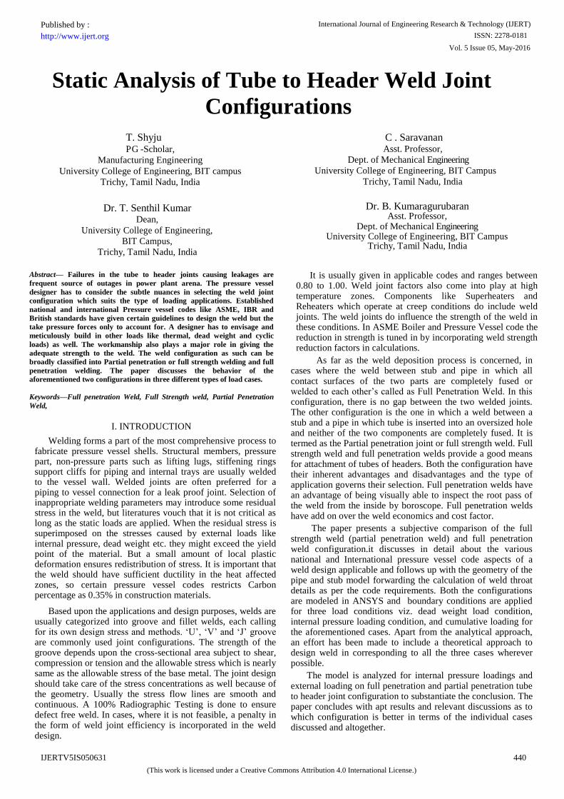
The second model taken for analysis is a spot face
set on
full penetration weld joint between tube and header. In this all
contact surfaces of the two parts are completely fused or welded
to each other. There is no residual gap or crevice between the
two welded parts. The major advantage of a full penetration
weld is that full inspection of
root pass profile of the weld from
inside (either by use of a boroscope or by visual inspection) is
possible. This configuration reduces the temperature gradient
across the weld and subsequently the thermal stresses and helps
in better fatigue strength. The disadvantages being high skilled
welders are required, difficult to achieve orientation and hence
less productive.
For spot face set on full penetration welding, the
headers needs to be spot faced. Spot face set on tube to header
full penetration joint configuration eliminates the need to fish
mouth the tube end for welding with the header. It is an open
root weld, but the recess can make for more difficult access to
the root. With proper equipment, spot face weld prep and the
tube hole can be machined in a single step. This configuration
uses tube hole diameter equal to or smaller than the tube
internal diameter. Tube to header full penetration weld joints
are designed according to the requirement of ASME Boiler and
Pressure Vessel Code. Fig 10.
shows the spot face set on groove
on the header.
The Model B, in contrast to Model A has a hole
drilled on pipe of size D23 mm. The pipe and the tube
specifications used in analysis remain similar to Model A. The
spot groove and other dimensions are calculated in line with the
British Standards.
Fig 10: Spot face set on groove on header
Fig 11: Spot face set on full penetration
weld
joint
The two models described above are modeled and analyzed
in ANSYS for various end loading conditions.
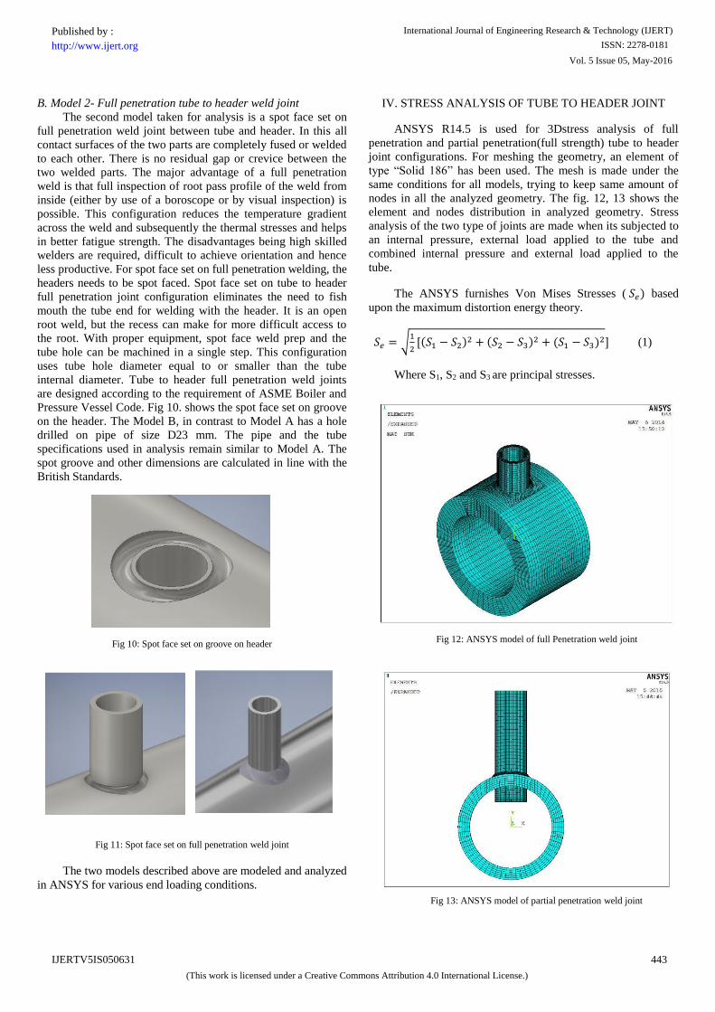
IV. STRESS ANALYSIS OF TUBE TO HEADER JOINT
ANSYS R14.5 is used for 3Dstress analysis of full
penetration and partial penetration(full strength)
tube to header
joint configurations. For
meshing the geometry, an element of
type “Solid 186” has
been used. The mesh is made under the
same conditions for all models, trying to keep same amount of
nodes in all the analyzed geometry. The fig. 12, 13
shows
the
element and nodes distribution in analyzed geometry.
Stress
analysis of the two type of joints are made when its subjected to
an internal pressure, external load applied to the tube and
combined internal pressure and external load applied to the
tube.
The ANSYS furnishes Von Mises Stresses
( 𝑆𝑒)
based
upon the maximum distortion energy theory.
𝑆𝑒 = √1
2[(𝑆1 − 𝑆2)2 + (𝑆2 − 𝑆3)2 + (𝑆1 − 𝑆3)2]
(1)
Where S1, S2
and S3
are principal stresses.
Fig 13: ANSYS model of partial penetration
weld
joint
Fig 12: ANSYS model of full Penetration
weld
joint
Vol. 5 Issue 05, May-2016
International Journal of Engineering Research & Technology (IJERT)
ISSN: 2278-0181http://www.ijert.org
IJERTV5IS050631
(This work is licensed under a Creative Commons Attribution 4.0 International License.)
Published by :
443

A. Stress due to internal pressure
Stress analysis of full penetration and partial penetration
tube to header weld joint is done when it is subjected to a
uniform internal pressure of 90 MPa. Von Mises stress
developed is shown in fig.14 and fig. 15.
Fig 14: Stress due to internal pressure in full penetration joint
Fig 15: Stress due to internal pressure in partial penetration joint
When the pipe is subjected to pressure forces,
Circumferential and longitudinal stresses get induced across the
cross section. When a hole is drilled in the pipe, stress
concentration due to the applied internal pressure increases
around the hole. The stress distribution is given by Kirsch
equations:
𝜎𝑡𝑥 =𝜎
4(4 +
3𝑟2
𝜌2 +3𝑟4
𝜌4 ) (2)
𝜎𝑡𝑦 =𝜎
4(2 +
3𝑟2
𝜌2 −3𝑟4
𝜌4 ) (3)
𝜎𝜌𝑥 =𝜎
4(2 +
𝑟2
𝜌2 −3𝑟4
𝜌4 ) (4)
𝜎𝜌𝑦 =𝜎
4(4 −
7𝑟2
𝜌2 +3𝑟4
𝜌4 ) (5)
𝜏𝑥 = 0
(6)
𝜏𝑦 = 0
(7)
Where,
σtx Normal Stress in X direction
σ ρx Tangential Stress in X direction
τx Shear Stress in X direction
σty Normal Stress in Y
direction
σ ρy Tangential Stress in Y
direction
τy Shear Stress in Y direction
r Radial distance from the edge of the hole
So, at r =0, σtx
is 2.5
times the longitudinal stress which
is
well validated by the model which gives the value as 112 MPa
and 177 MPa at the edges
for Full and Partial Penetration
respectively.
B. Stress due to external load applied to the tube
Fig 16: Stress due to external load in full penetration joint
Fig 17: Stress due to external load in partial penetration joint
Vol. 5 Issue 05, May-2016
International Journal of Engineering Research & Technology (IJERT)
ISSN: 2278-0181http://www.ijert.org
IJERTV5IS050631
(This work is licensed under a Creative Commons Attribution 4.0 International License.)
Published by :
444
When an external tensile load of 500Kg is applied on the
face of the tube, both normal and shear stresses will develop in
the weld.
Fig 18: Full penetration
weld
joint
Fig 19: Partial penetration
weld
joint
Average normal stress Sn
at an angle φ
is given by
𝑆𝑛 =(𝐹𝑐𝑜𝑠∅)(𝑐𝑜𝑠∅+𝑠𝑖𝑛∅)
𝑤𝜋𝑑
(8)
Average shear
stress Ss at an angle φ is given by
𝑆𝑠 =(𝐹𝑠𝑖𝑛∅)(𝑐𝑜𝑠∅+𝑠𝑖𝑛∅)
𝑤𝜋𝑑
(9)
Maximum shear stress
Ss
occurs at φ = 67.5°.
𝑆𝑠 =1.2𝐹
𝑤𝜋𝑑
(10)
max. 𝑆𝑛 =0.5𝐹
𝑤𝜋𝑑
(11)
max.combined
stress
𝑆′𝑠 = √[(𝑆𝑛
2)
2
+ 𝑆𝑠2] =
1.22𝐹
𝑤𝜋𝑑
(12)
The Von Mises stresses developed in the weld is shown in the fig.16
and fig.17.
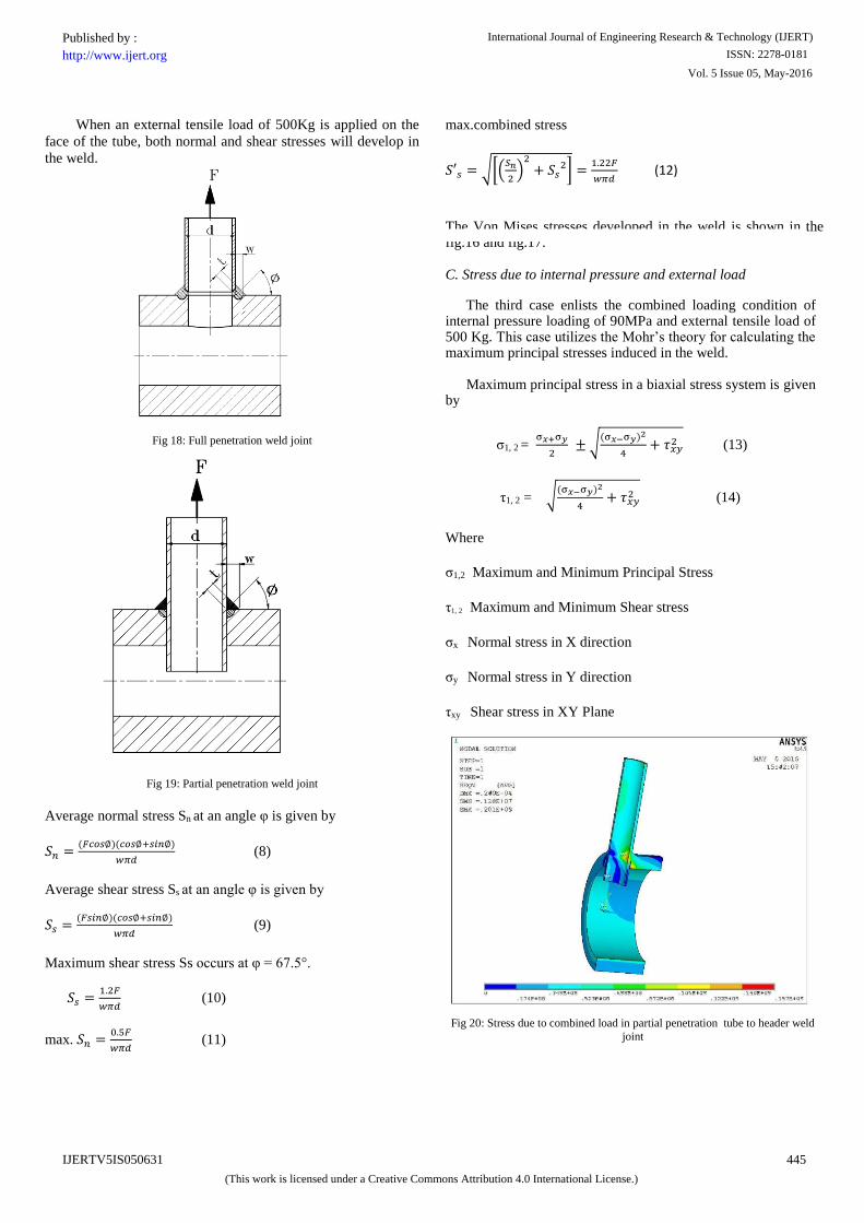
C.
Stress due to internal pressure and external load
The third case
enlists the combined
loading condition
of internal pressure loading of 90MPa and external
tensile
load of 500 Kg.
This case utilizes the Mohr’s theory for calculating the maximum principal stresses induced in the weld.
Maximum principal stress in a biaxial stress system is
given by
σ1, 2 =
σ𝑥+σ𝑦
2
± √(σ𝑥−σ𝑦)2
4+ 𝜏𝑥𝑦
2 (13)
τ1, 2
= √(σ𝑥−σ𝑦)2
4+ 𝜏𝑥𝑦
2 (14)
Where
σ1,2 Maximum and Minimum Principal Stress
τ1, 2
Maximum and Minimum Shear stress
σx Normal stress in X direction
σy Normal stress in Y direction
τxy
Shear stress in XY Plane
Fig 20: Stress due to combined load in
partial
penetration
tube to header weld
joint
Vol. 5 Issue 05, May-2016
International Journal of Engineering Research & Technology (IJERT)
ISSN: 2278-0181http://www.ijert.org
IJERTV5IS050631
(This work is licensed under a Creative Commons Attribution 4.0 International License.)
Published by :
445
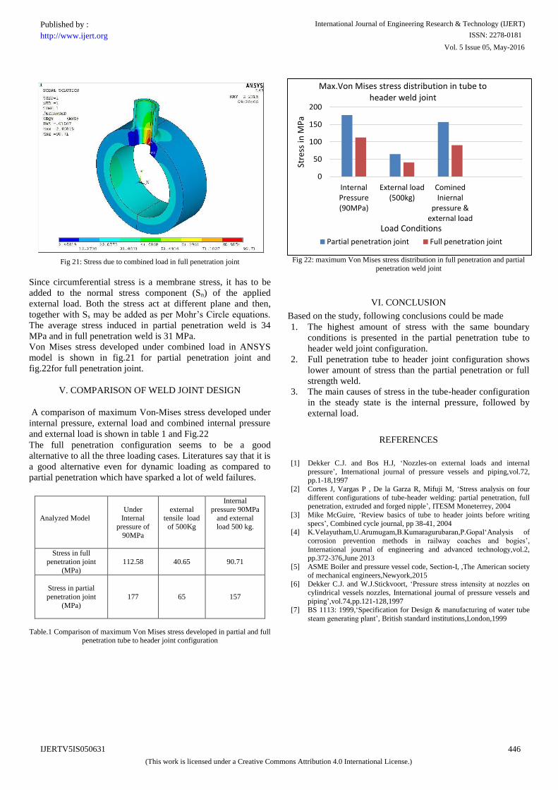
Fig 21: Stress due to combined load in full penetration joint
Since circumferential stress is a membrane
stress, it has to be
added to the normal stress component (Sn) of the applied
external load. Both the stress
act at different plane and then,
together with Ss
may be added as per Mohr’s Circle equations.
The
average stress induced in partial penetration weld is 34
MPa and in full penetration weld is 31 MPa.
Von Mises stress developed under combined load in ANSYS
model is shown in fig.21
for partial penetration joint and
fig.22for full penetration joint.
V. COMPARISON
OF WELD JOINT DESIGN
A comparison of maximum Von-Mises stress developed under
internal pressure, external load and combined internal pressure
and external load is shown in table 1 and Fig.22
The full penetration configuration seems to be a good
alternative to all the three loading cases. Literatures say that it is
a good alternative even for dynamic loading as compared to
partial penetration which have sparked a lot of weld failures.
Analyzed Model
Under
Internal pressure of
90MPa
external
tensile load of 500Kg
Internal
pressure 90MPa
and external load 500 kg.
Stress in full
penetration joint
(MPa)
112.58
40.65
90.71
Stress in partial
penetration joint
(MPa)
177
65
157
Table.1 Comparison of maximum Von Mises stress developed in partial and full penetration tube to header joint configuration
Fig 22: maximum Von Mises stress distribution in full penetration and partial
penetration weld joint
VI.
CONCLUSION
Based on the study, following conclusions could be made
1.
The highest amount of stress with the same boundary
conditions is presented in the partial penetration tube to
header weld joint configuration.
2.
Full penetration
tube to header
joint configuration shows
lower amount of stress than the partial penetration or full
strength weld.
3.
The main causes of stress in the tube-header configuration
in the steady state is the internal pressure, followed by
external load.
REFERENCES
[1]
Dekker C.J. and Bos H.J, ‘Nozzles-on external loads and internal
pressure’, International journal of pressure vessels and piping,vol.72, pp.1-18,1997
[2]
Cortes J, Vargas P , De la Garza R, Mifuji M, ‘Stress analysis on four
different configurations of tube-header welding: partial penetration, full penetration, extruded and forged nipple’, ITESM Moneterrey, 2004
[3]
Mike McGuire, ‘Review basics of tube to header joints before writing
specs’, Combined cycle journal, pp 38-41,
2004
[4]
K.Velayutham,U.Arumugam,B.Kumaragurubaran,P.Gopal‘Analysis of
corrosion prevention methods
in railway coaches and bogies’,
International journal of engineering and advanced technology,vol.2,
pp.372-376,June 2013
[5]
ASME Boiler and pressure vessel code, Section-I,
,The American
society
of mechanical engineers,Newyork,2015
[6]
Dekker C.J. and W.J.Stickvoort, ‘Pressure stress intensity at nozzles on
cylindrical vessels
nozzles, International journal of pressure vessels and
piping’,vol.74,pp.121-128,1997
[7]
BS 1113: 1999,‘Specification for
Design & manufacturing of water tube
steam generating plant’, British standard institutions,London,1999
0
50
100
150
200
InternalPressure(90MPa)
External load(500kg)
CominedIniernal
pressure &external load
Stre
ss in
MP
a
Load Conditions
Max.Von Mises stress distribution in tube to header weld joint
Partial penetration joint Full penetration joint
Vol. 5 Issue 05, May-2016
International Journal of Engineering Research & Technology (IJERT)
ISSN: 2278-0181http://www.ijert.org
IJERTV5IS050631
(This work is licensed under a Creative Commons Attribution 4.0 International License.)
Published by :
446