static and dynamic characteristics of double-mode … devices volume 6 number 1 march 2017 1 static...
TRANSCRIPT

Electronic Devices Volume 6 Number 1 March 2017 1
Static And Dynamic Characteristics of Double-Mode Inverter Under The Control ofSingle Current Loop
Jian ChuTianjin University of Technology and EducationTianjin, 300222, [email protected]
ABSTRACT: This study aimed to explore static and dynamic characteristics of double-mode inverter under the control ofsingle current loop. A model was established based on LC filter using grid-connected operation. With output power controlledby single current loop control method, key control parameters were figured out. Based on the simulation model establishedunder Matlab/Simulink environment, favorable static and dynamic characteristics of double-mode inverter controlled bysingle current loop were verified.
Keywords: Double- Mode Inverter, Grid- Connected Operation, Microgrid
Received: 1 October 2016, Revised 8 November 2016, Accepted 12 November 2016
© 2017 DLINE. All Rights Reserved
1. Introduction
With the development and application of new energy, distributed power generation system will become the developmentdirection of electric heating in the future [1]. A power electronic interface device called grid-connected inverter which can absorbor feedback energy to large power grid is generally equipped in distributed power generation system. Inverter in microgrid isapplicable to grid-connected operation mode and independent operation mode, thus it is usually termed as double-modeinverter [2].
When power grid operates normally, inverter operating in grid-connected mode transfers redundant electric energy into powergrid. When power grid fails, inverter will disconnect with power grid and operate in independent model to provide reliableelectric energy [3,4]. Switching between two modes is usually smooth and rapid. Such a function similar to Uninterrupted PowerSupply can effectively ensure reliable and safe operation of local load (UPS) [5,6]. Double-mode inverter plays a key role in thewhole set of microgrid. How to improve the performance of double-mode inverter to meet the requirements of energy transmission,electric power quality and user diversity has become a hotspot of research.

2 Electronic Devices Volume 6 Number 1 March 2017
Based on the analysis of single cycle control method, Jing Xiao from Shandong University realized digital single cycle controlmethod, applied it into double-mode inverter operated under independent mode to highlight its advantages and made verificationin MATLAC simulation environment [7]. To solve the problem of low respond speed of constant voltage control strategy of Z-source inverter, Harbin Institute of Technology designed grid-connection which can realize unity-power-factor grid connectionand independent model of Z-source inverter which can ensure stable output voltage [8]. Based on closed-loop control systemof single-phase inverter, Sun Xiangdong, Ren Biying, Zhang Qi et al. made analysis on the systematic performance of inverterunder grid-connected mode, off-grid mode and smooth switching of modes [9]. To completely eliminate computation delay ofactive damping inner loop and grid-connected current outer loop, Aircraft Electric Power Source and Aerospace TechnologyKey Lab proposed double sampling model based real time computation method and moreover verified with experiment takingsingle phase LCL grid connected inverter as an example [10].
Based on the double-mode inverter operated under grid-connection mode, this study calculated key control parameters usingsingle current loop control method, calculated key and established a simulation model under Matlab/Simulink environment toexplore static and dynamic characteristics of double-mode inverter controlled by single current loop.
2. Selection of Filter of Double- Mode Inverter
In microgrid, there are mainly three kinds of commonly used filters for double-mode inverter, i.e., L filter, LC filter and LCL filter[11], as shown in figure 1. Three kinds of filters have their own features, thus we should make a choice based on the actualsituation.
a. L filter b. LC filter c. LCL filter
Figure 1. Structure of common filters
Due to poor high frequency harmonic attenuation performance, L filter with simple structure requires higher inductance or lowerswitching frequency, in order to achieve ideal filter effect. Moreover, when double-mode inverter operating off grid controlsoutput voltage, output voltage waveform is Pulse-Width Modulation (PWM) as single L filter cannot filter voltage; therefore, Lfilter suitable for grid-connection inverter with small power and high switching frequency is not applicable for double-modeinverter.
Compared to L filter, LCL filter is characterized by third order lowpass filtering. For the same harmonic standards and lowswitching frequency, LCL with relatively small filter inductance cam effectively reduce volume and loss. However, LCL filter alsohas defects. Due to the increase of capacitance branch, current control system turns from first order to third order, which makedesign of control system more difficult, and resonance limits wide application of LCL filter [12]. In formula (1), correspondingBode diagram is shown in figure 2 if L1 = 2×10⁻³Η, C = 12×10−6F, L2 = 0.377×10⁻³H. It indicates that, resonance generated byLCL filter within certain frequency can affect stability of the system.
sLLsCLLsVs
i
g
)(1
)()(I
213
12 ++= (1)
For LCL filter such a third order system, detailed resonance can be figured out through formula (2). It is not hard to see that, threeenergy storage elements all have impact on resonant frequency.
CLLLL
21
21res
+=ω (2)

Electronic Devices Volume 6 Number 1 March 2017 3
Figure 2. Bode diagram of LCL filter
LC filter has good filtering performance. When double-mode inverter operates in grid-connected mode, inductance can effectivelyfilter grid-connected current. LC filter can not only effectively decay high frequency harmonic component in output voltage toobtain good waveform but also has advantages in cost [13]. Usually, double-mode inverter uses LC filter. This study also selectsLC filter for research. When double-mode inverter operates under grid-connection mode, transmission characteristics withregard to output voltage and current is shown in formula (3).
LssVs
i
g 1)()(I
= (3)
The size of L is based on Total Harmonic Distortion (THD). Taking double-mode inverter with rated power of 25kVA, this studydesigned filter parameter that meets THD< 4%. When switching frequency is 6 kHz, direct current side voltage is 700 V andmodulation degree is 0.768, harmonic voltage output by double-mode inverter under rated power is shown in figure 3.
Figure 3. Harmonic voltage amplitude
Harmonic current computation formula is shown in formula (4). In the formula, bω is fundamental wave angular frequency andh=2, 3, 4 …
bhLhuhi
ω××=
)()( (4)
Computation formula for THD is shown in formula (5). In the formula, ib is effective value of fundamental current, and at first, Lis taken as 2 mH.

4 Electronic Devices Volume 6 Number 1 March 2017
%100)(
THD
420
2
2
×=∑
=
b
h
i
hi(5)
When inverter is operated with rated power, Ia = 38A, THD = 3.15%; when it is operated with 80% rated power, Ia = 30A and THD= 3.99%; when it is operated with 60% rated power, Ia = 23A, THD = 5.20%. With rated power, 2 mH of filter inductance can makeTHD< 4%.
3. Analysis of Doubleomode Inverter Opertaed Under Grid- Connected Mode
3.1 Mathematical model of double-mode inverterWhen general mathematical model established for three-phase double-mode inverter, the assumption is as follows [14].
1) Voltage (ea, eb, ec) is pure sinusoidal voltage with stable three phases.
2) Filter inductance L is linear, without considering saturation.
3) Switching loss resistance is reckoned in R, and the switch is perfect.
Firstly, logic switch function is defined as
)cb( 、、aksk = .
Sk = {Kirchhoff Voltage Law is applied in a phase loop of double-mode inverter.
dia + Ria = ea - (vaN + vNO) (7)
Under the condition of a-phase top tube breakover and down tube shutoff, Sa = 1 and vaN = Vdc. Under the condition of a-phasetop tube shutoff and down tube breakover, Sa = 0 and vaN = 0. Formula (7) can be written into:
dia + Ria = ea - (vdc sa + vNO) (8)
Similarly, b-phase and c-phase voltage loop equation can be obtained, as follows:
dib + Rib = eb - (vdc sb + vNO) (9)
dic + Ric = ec - (vdc sc + vNO) (10)
Considering the research object is a three-phase balanced system, we have:
∑ ek = ∑ ik = 0 (11)
Combining (2-8) ~ (2-11), we get:
vdc ∑ sk (12)
Moreover, at any time point, double-mode inverter always has three conductive switching tunes, and there are totally eightswitching modes. Therefore, direct current side current idc can be confirmed by the following formula:
1 (upper bridge arm breakover, lower bridge arm shutoff)0 (upper bridge arm shutoff, lower bridge arm breakover)
(6)
dt
dt
dt
dt
k =a,b,c
k =a,b,c3
k =a,b,c
L
L
L
L
vNO = -

Electronic Devices Volume 6 Number 1 March 2017 5
(13)
Kirchhoff ’ s Current Law is used into direct current side capacitance, we get:
Ldcdc ii
dtdvC −= (14)
Substitute formula (12) into formula (8) to (10) and (13) into (14), we get a mathematical model described by switching functionin three-phase static coordinate by putting the above two formulas together.
⎪⎪⎪⎪⎪
⎩
⎪⎪⎪⎪⎪
⎨
⎧
−=
−−=+
−−=+
−−=+
∑
∑
∑
∑
=
=
=
=
cbakLkk
dc
cbakkcdccc
c
cbakkbdcbb
b
cbakkadcaa
a
isidt
dvC
ssveRidtdi
ssveRidtdi
ssveRidtdi
,,
,,
,,
,,
)31(L
)31(L
)31(L
(15)
Suppose voltage of double-mode inverter on alternating current side is au , bu and cu respectively. According to the mathematicalmodel described by formula (15), we get:
⎪⎪⎪⎪
⎩
⎪⎪⎪⎪
⎨
⎧
−=
−=
−=
∑
∑
∑
=
=
=
)31(
)31(
)31(
,,
,,
,,
cbakkcdcc
cbakkbdcb
cbakkadca
ssvu
ssvu
ssvu
(16)
Such mathematical model for double-mode inverter in three-phase static coordinate contains alternating quantity, which is notbeneficial to design of control system. Thus we can transform three-phase static coordinate into rotating coordinate systemwhich synchronously rotates with fundamental frequency [15]. After transformation, all alternating quantities which have thesame frequency with fundamental wave of power system are turned into direct current quantity, which can simplify design ofcontrol system. Coordinate transformation can be divided into two categories, i.e., equal quantity conversion and equal powerconversion. Difference of them lies on whether transformational matrix is orthorhombic or not. This study uses equal quantitycoordinate conversion.
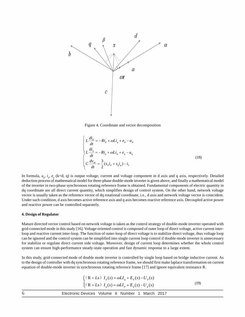
In figure 4, there is an 120° between a axis, b axis and c axis; β axis and α axis is perpendicular; α axis and a axis is coincident andthere is an 90° angle between a axis (α axis) and β axis; angle between a axis and d axis is ωt. It can be deduced that, vector xtransforming from three-phase static coordinate (abc) into two-phase rotational coordinate meets the formula
⎥⎦
⎤⎢⎣
⎡
⎥⎥⎥
⎦
⎤
⎢⎢⎢
⎣
⎡•⎥
⎦
⎤⎢⎣
⎡−
=⎥⎦
⎤⎢⎣
⎡
b
a
q
d
vv
vv
32
31
01
cossinsincos
θθθθ
(17)
Substituting formula (17) into formula (15), we get a mathematical model of three-phase double-mode inverter in two-phaserotational coordinate:
idc = ∑ ik Skk=a,b,c
6 Electronic Devices Volume 6 Number 1 March 2017
⎪⎪⎪
⎩
⎪⎪⎪
⎨
⎧
−+=
−++−=
−++−=
Lqqdddc
qqdqq
ddqdd
iisisdt
dvC
ueLiRidtdi
L
ueLiRidtdiL
)(23
ω
ω
(18)
In formula, uk, ik, ek (k=d, q) is output voltage, current and voltage component in d axis and q axis, respectively. Detaileddeduction process of mathematical model for three-phase double-mode inverter is given above, and finally a mathematical modelof the inverter in two-phase synchronous rotating reference frame is obtained. Fundamental components of electric quantity indq coordinate are all direct current quantity, which simplifies design of control system. On the other hand, network voltagevector is usually taken as the reference vector of dq rotational coordinate, i.e., d axis and network voltage vector is coincident.Under such condition, d axis becomes active reference axis and q axis becomes reactive reference axis. Decoupled active powerand reactive power can be controlled separately.
4. Design of Regulator
Mature directed vector control based on network voltage is taken as the control strategy of double-mode inverter operated withgrid-connected mode in this study [16]. Voltage-oriented control is composed of outer loop of direct voltage, active current inter-loop and reactive current inter-loop. The function of outer-loop of direct voltage is to stabilize direct voltage, thus voltage loopcan be ignored and the control system can be simplified into single current loop control if double-mode inverter is unnecessaryfor stabilize or regulate direct current side voltage. Moreover, design of current loop determines whether the whole controlsystem can ensure high-performance steady-state operation and fast dynamic response to a large extent.
In this study, grid-connected mode of double mode inverter is controlled by single loop based on bridge inductive current. Asto the design of controller with dq synchronous rotating reference frame, we should first make laplace transformation on currentequation of double-mode inverter in synchronous rotating reference frame [17] and ignore equivalent resistance R.
⎪⎩
⎪⎨⎧
−+=+
−+=+
)()()(R)()()(R
sUsELIsILssUsELIsILs
qqdq
ddqd
ω
ω
)(
)(
(19)
Figure 4. Coordinate and vector decomposition

Electronic Devices Volume 6 Number 1 March 2017 7
Thus control system of major loop is obtained, as shown in figure 5.
Figure 5. Major loop control graph
It can be seen from figure 5 that, current in d axis and q axis is coupled in the control system. Usually, feedforward decouplingis used for designing controller. When current regulator is controlled by proportional integral (PI), control equation for ud anduq is as follows:
dqddiI
ipd eLiiis
KKu ++−+−= ∗ ω))(( (20)
dqqiI
ipq Liiis
KKu ω+−+−= ∗ ))(( (21)
From formula (20) and (21), we get PI control diagram of double-mode inverter in dq coordinate (Table 6).
Figure 6. PI control diagram of double-mode inverter in dq coordinate

8 Electronic Devices Volume 6 Number 1 March 2017
In figure 7, Kip and KiI is proportional coefficient and integral coefficient. Substitute formula (20) and (21) into formula (19).Considering delay of current loop signal sampling and low inertia of PWM control and ignoring intervention of network voltage,we can get current loop control structure. d axis is taken as an example.
Figure 7. Current loop control structure
Its closed loop transfer function is:
iIip
iIipi KsKRLs
KsKsG
++++
=)(
)()( 2 (22)
Parameters of current loop can be designed according to typical type I or II system. The former can make current have goodtracking performance; but once network voltage is interfered, it is hard to recover. Though overshoot is large during trackingcurrent step command with type II system, current loop can recover quickly from intervention. This study selects typical typeII system and sets Kip = 4.8 and KiI = 3840. Referring to practical parameters, we suppose L=2 mH and R=0.06 Ω. Next, we getamplitude-frequency and phase-frequency response curve of transfer function. As shown in figure 8, bandwidth of current interloop is wide and response is quite fast.
Figure 8. Magnitude versus phase plot of close loop of grid-connection controller
5. Grid-Connected Operation Simulation
To verify the effectiveness of controller designed above and compare PI parameters designed with typical type I or II system, weestablish a simulation model in Matlab/Simulink. Detailed hardware parameters are shown in table 1.
In the simulation model, direct current side is parallelly connected with 700V direct current and alternating current side isconnected with direct current with 380V. Reactive current is set as 0 and active current is set as 10A at first. At

Electronic Devices Volume 6 Number 1 March 2017 9
Table 1. simulation parameter of hardware of double-mode inverter
Figure 9. Arc voltage and current waveforms under grid-connection mode
Figure 10. FFT analysis of output current of double-mode inverter

10 Electronic Devices Volume 6 Number 1 March 2017
0.1 s, the set value turns to be 30 A and at 0.15 s, 30 Ved interventions occur. PI parameter KiP and KiI designed by typical typeI system is 4 and 120 respectively, and parameters designed by typical type II system is 4.8 and 3840 respectively. Simulationwaveform is shown in figure 9 and 10.
Figure 11 is comparison of step response of current id when current regular is designed in two different ways.
6. Conclusion
It can be seen from figure 9 and 10, when single current loop controlled double-mode inverter operates in grid-connection mode,it can output current with good quality; when current order changes suddenly, the inverter can rapidly track output current orderand shows up favorable static and dynamic characteristics.
It can be seen from figure 11 that, when current regulator is designed according to typical type 1 system, current id shows goodtracing performance; but once ed disturbance occurs, recovery time of id is long; however, when current regulator is designedaccording to typical type 2 system, current loop can recover rapidly under the disturbance of ed.
Conflict of InterestThe author(s) confirm that this article content has no conflicts of interest.
References
[1] Shuang, Y. (2014). Development Pattern of Distributed Energy Resource in the Environment of Intelligent Power Grid.Science and Technology, (24) 42-42.
[2] Lingemann, M., Ortjohann, E., Schmelter, A. (2010). Inverters as Smart Grid Interface - Standardized Feeding Modes forDifferent Distributed Generation Units and Grid Requirements, Power Electronics, (4) 14-19.
[3] Xucheng, L., Pin, Y., Yin, L. (2011). Research of Dual Modes Inverter Based on DSP, Power Electronics, 45 (2) 56-59.
[4] Debin, Z., Fang, L., Haizhen, X., Xing, Z. (2012). Control Strategy for Distributed Generation Inverter in Two Modes Operationof Microgrid. Power Electronics, 46 (10) 9-10.
[5] Hui, X. (2014). Analysis of UPS with Non-output Transformer. Components and Powder, (4) 134-141.
[6] Jianjun, J. (2013). Working Principle of UPS and its Application in Instruments in Computer Room. Technological Developmentof Enterprise, (4) 20-21.
Figure 10. Comparison of step response of current id

Electronic Devices Volume 6 Number 1 March 2017 11
[7] Guangxian, Z. (2014). Design and Implementation of Double-pattern Inverter. Shandong University.
[8] Qian, Y., Huihui, D., Yanbin, Q. (2014). Research on Control Strategy of Z-Source Inverter with Double Mode of Grid-Connection and Stand-Alone. Electrical Measurement & Instrumentation, 51 (6) 55-59.
[9] Xiangdong, S., Biying, R., Qi, Z., Gang, L. (2014). Grid-connected and Off-grid Modes for a Single-phase Micro-grid Inverter.Power Electronics, 48 (1) 1-3.
[10] Donsheng, Y., Xinbo, R., Heng, W. (2015). A Real-time Computation Method with Dual Sampling Modes to Improve theCurrent Control Performance of the LCL-type Grid-connected Inverter. Proceedings of the CSEE, (6) 1445-1454.
[11] Zhiying, X. (2009). Current Control Technology of Grid-connected Inverter. Nanjing University of Aeronautics andAstronautics.
[12] Yingping, Y., Kaiping, L., Lin, W. (2011). Control Strategy of LCL-filter-based Inverter for Photovoltaic Grid Connection.Electric Power Automation Equipment, 31 (12) 54-58.
[13] Ji, J., Shanxu, D., Zhongwei, C. (2012). Research on Control Strategy for Three-Phase Double Mode Inverter. Transactionsof China Electrotechnical Society, (2) 52-58.
[14] Xiaohuan, W., Chunjiang, Z., Feng, D. (2010). Design and Implementation of Three-phase Inverter Controller with DoubleMode of Grid-connection and Stand-alone. Power Electronics, 44 (12) 82-84.
[15] Guiying, L., Shiping, S., Zhiqing, Q. (2010). A New Harmonic Detection Method for Three-phase Four-Wire System Basedon Orthogonal Transformation of Multi-Frequency Rotating Coordinate. Power System Technology, 34 (7) 87-93.
[16] Yufeng, W., Linwei, Z., Tao, L., Guohua, L. (2014). Research on Three-phase VSI Cascade Photovoltaic Grid-connectedInverter. Power Electronics, 48(4) 55-57.
[17] Lianfu, W., Peiyan, F., Xiaohua, S. (2013). New Passive Lossless Snubber Circuit. Chinese Journal of Power Sources, 37(2)285-288.