static and thermal analysis on mechanical shaft using titanium alloy · 2018-04-22 · static and...
TRANSCRIPT
© April 2018 | IJIRT | Volume 4 Issue 11 | ISSN: 2349-6002
IJIRT 146058 INTERNATIONAL JOURNAL OF INNOVATIVE RESEARCH IN TECHNOLOGY 1159
Static and Thermal Analysis on Mechanical Shaft
Using Titanium Alloy
Rishabh1, Prateek Srivastava
2, Atul Raj Shukla
3, Bhupender Singh
4
1,2,3 Graduate Student, Mechanical Engineering, Faculty of Engineering and Technology Manav Rachna
International Institute of Research and Studies, Faridabad, Haryana, India 4Assistance professor, Mechanical Engineering, Faculty of Engineering and Technology, Manav Rachna
International Institute of Research and Studies, Faridabad, Haryana, India
Abstract- A Shaft is consisted to various loads like
torsion, axial load, and bending moment as well as for
compressive, the loads might be uniformly distributed,
and point, impact in nature and the shaft may be
stationary or rotating. In this paper we use the
mechanical shaft to check the bending moment, axial
load, torsion and thermal transient in a shaft for
calculating equivalent stress, equivalent elastic strain,
directional deformation, total heat flux and directional
heat flux. The shaft is connected to ball bearing at both
ends, while we take titanium alloy as a material for
doing analyses in mechanical Shaft. We use to design
the Shaft in Catia software and the analysis parameter
is done on Ansys software
Index Terms- Shaft, Catia, Ansys, Bending Moment,
Strain, Stress
1. INTRODUCTION
A shaft is a stationary or rotating device, it use to
transfer of Power from one body to another. It is
generally used for bending, torsion, tension or
compression loads for isolation or combined modes.
The load may be uniformly distributed, point, impact
loading. The shaft structure are generally circular
either solid or hollow. The shaft is a transmitting
device which uses to transfer power from one body to
another, and generally shafts are used for combined
loads. A shaft which rotates and have steady loads
should have a full reverse load, and each portion of
shaft is with tension and compressive loads. The shaft
should have strength, rigidity (torsion and axial), and
have to maintain critical speed. The shaft design
should be in these ways that the deflection which is
produced by the devices should be minimum and in
the tolerance limit. Lateral deflection in shaft might
increase the vibration and increase of noise. In this
paper we use to design the shaft in catia software of
different material of shaft and the analyzing of shaft
is done on Ansys software for different load
condition to check the bending moment.
Notation
T- Torque
d – Diameter of shaft
J- Polar moment of inertia
M- Moment
I – Moment of inertia
σb – Bending moment
σa – Axial load
τ - Torsion
F- Force
A- Total surface Area
di- inner diameter
do- outer diameter
k -Thermal conductivity
Qx- Heat flux
2. ANALYTICAL METHOD
In Analytical Method, we use to give the momentum
to the shaft and then we use to calculate the
deformation in the shaft and also to calculate the
stress and strain in that particular shaft.
1. To calculate the torsion we use,
J = 𝜋(do – di)4
32
τ = T X d
2J
2. Bending Moment
I = 𝜋(do – di)4
64
© April 2018 | IJIRT | Volume 4 Issue 11 | ISSN: 2349-6002
IJIRT 146058 INTERNATIONAL JOURNAL OF INNOVATIVE RESEARCH IN TECHNOLOGY 1160
σb = M X d
2I
3. Axial load
A = 𝜋(do2– di
2)
4
σa = F
A
4. Heat flux (conduction)
Qx = -k dT
dx
3. FINETE ELEMENT METHOD
This is a type of method used for solving problems in
mathematical physics using numerical method. In
these finite element method major problems used to
solved using structural analysis. In this method
generally consists of different complicated geometry
with different material like titanium alloy and used to
calculate equivalent stress, equivalent elastic strain,
and directional deformation which is generally very
complicated with Mathematical solution. And with
the help of these we use to calculate heat flux while
total and directional also.
4. DESIGN AND DATA
Mechanical shaft is used to modeled in CATIA V5
R20, the mechanical shaft have different geometry
condition as it is used to assemble in CATIA with 3D
model. As the shaft is at the middle of geometry and
ball bearing at the both end, and the arrangement is
done as the shaft have rotating moment. The shaft
consists of different geometrical condition as Shaft
inner diameter= 30 mm, Shaft Outer diameter is 45
mm, length of shaft = 1100mm, diameter of ball in
ball bearing= 25mm, No of ball bearing= 10, centre
of ball bearing from centre= 67.5 mm, inner diameter
of ball bearing= 85mm, outer diameter of ball
bearing= 185mm, diameter of bearing inside ball
bearing= 120mm, diameter of bearing outside ball
bearing= 150mm, thickness of ball bearing= 50mm,
and distance between two ball bearings= 1000mm.
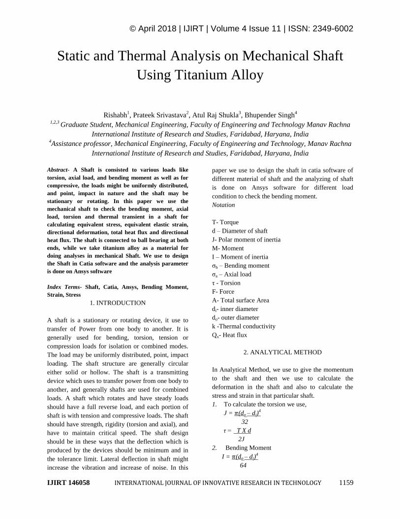
A) Sketch of shaft in catia[12]
Fig 1: Sketch of shaft in catia
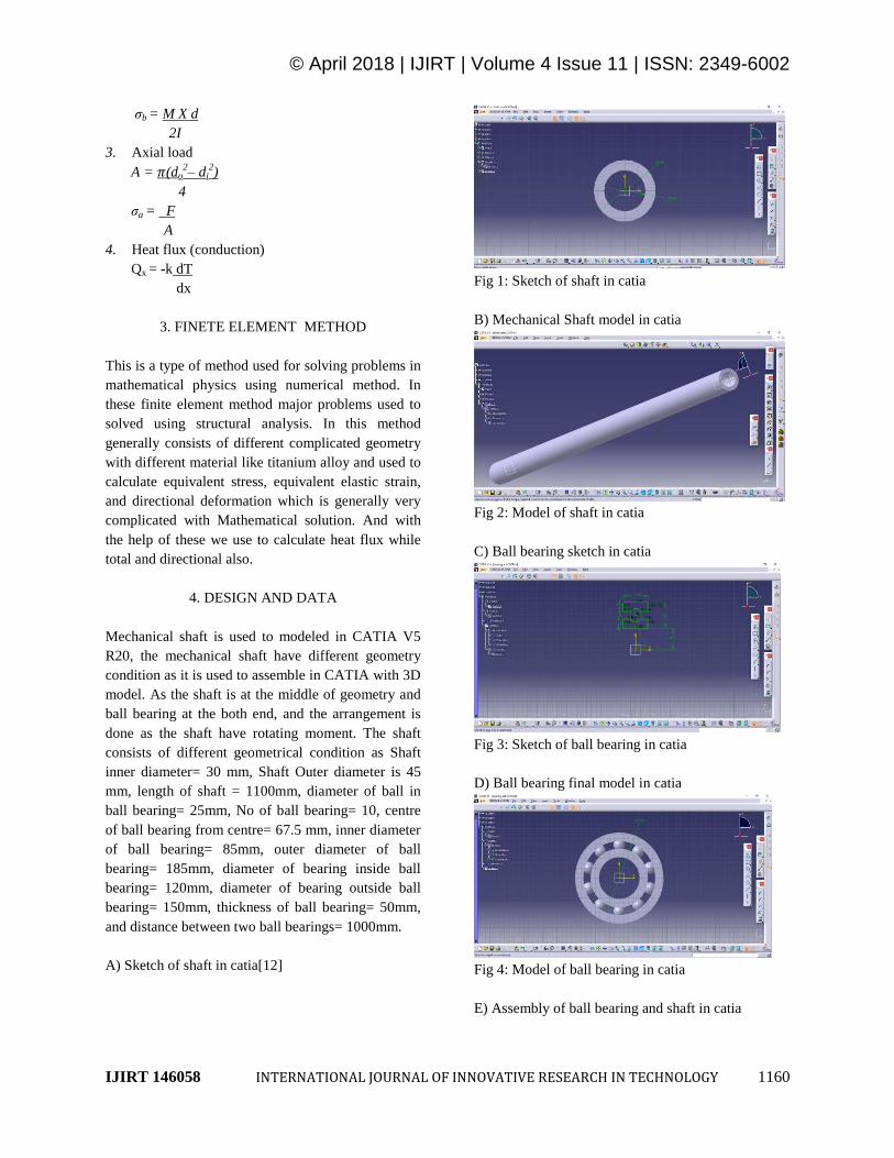
B) Mechanical Shaft model in catia
Fig 2: Model of shaft in catia
C) Ball bearing sketch in catia
Fig 3: Sketch of ball bearing in catia
D) Ball bearing final model in catia
Fig 4: Model of ball bearing in catia
E) Assembly of ball bearing and shaft in catia
© April 2018 | IJIRT | Volume 4 Issue 11 | ISSN: 2349-6002
IJIRT 146058 INTERNATIONAL JOURNAL OF INNOVATIVE RESEARCH IN TECHNOLOGY 1161
Fig 5: Assembled model of ball bearing and shaft in
catia
5. ANALYTICAL RESULTS
In this analyzing of mechanical shaft we use
Titanium alloy as a material for axial load, bending
moment, and torsion, for checking the maximum and
minimum value of Equivalent stress, equivalent
elastic strain, and directional deformation. And for
thermal transient we use to calculate directional flux
and total heat flux for 500 watt, 600 watt, 700 watt,
800 watt, 900 watt and 1000 watt.[13]
1. Torsion
A) Equivalent Stress
Fig 6: equivalent stress in Torsion
B) Equivalent Elastic Strain
Fig 7: equivalent elastic strain in Torsion
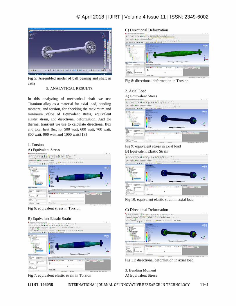
C) Directional Deformation
Fig 8: directional deformation in Torsion
2. Axial Load
A) Equivalent Stress
Fig 9: equivalent stress in axial load
B) Equivalent Elastic Strain
Fig 10: equivalent elastic strain in axial load
C) Directional Deformation
Fig 11: directional deformation in axial load
3. Bending Moment
A) Equivalent Stress
© April 2018 | IJIRT | Volume 4 Issue 11 | ISSN: 2349-6002
IJIRT 146058 INTERNATIONAL JOURNAL OF INNOVATIVE RESEARCH IN TECHNOLOGY 1162
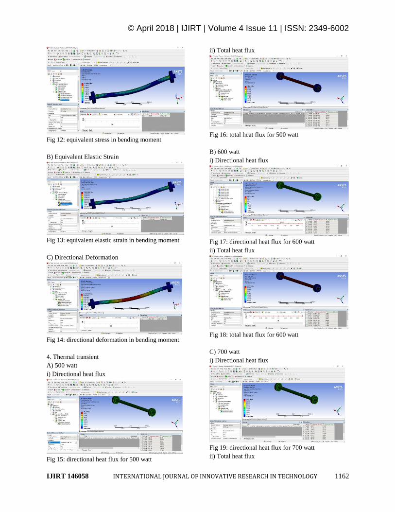
Fig 12: equivalent stress in bending moment
B) Equivalent Elastic Strain
Fig 13: equivalent elastic strain in bending moment
C) Directional Deformation
Fig 14: directional deformation in bending moment
4. Thermal transient
A) 500 watt
i) Directional heat flux
Fig 15: directional heat flux for 500 watt
ii) Total heat flux
Fig 16: total heat flux for 500 watt
B) 600 watt
i) Directional heat flux
Fig 17: directional heat flux for 600 watt
ii) Total heat flux
Fig 18: total heat flux for 600 watt
C) 700 watt
i) Directional heat flux
Fig 19: directional heat flux for 700 watt
ii) Total heat flux
© April 2018 | IJIRT | Volume 4 Issue 11 | ISSN: 2349-6002
IJIRT 146058 INTERNATIONAL JOURNAL OF INNOVATIVE RESEARCH IN TECHNOLOGY 1163
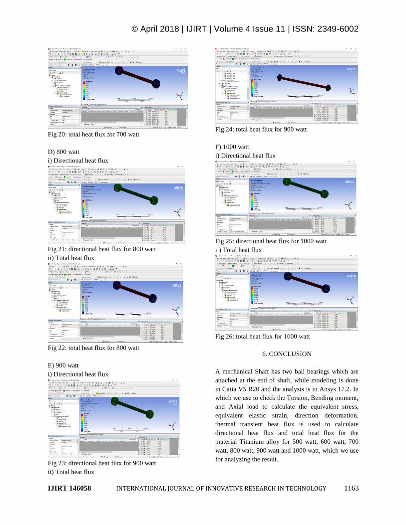
Fig 20: total heat flux for 700 watt
D) 800 watt
i) Directional heat flux
Fig 21: directional heat flux for 800 watt
ii) Total heat flux
Fig 22: total heat flux for 800 watt
E) 900 watt
i) Directional heat flux
Fig 23: directional heat flux for 900 watt
ii) Total heat flux
Fig 24: total heat flux for 900 watt
F) 1000 watt
i) Directional heat flux
Fig 25: directional heat flux for 1000 watt
ii) Total heat flux
Fig 26: total heat flux for 1000 watt
6. CONCLUSION
A mechanical Shaft has two ball bearings which are
attached at the end of shaft, while modeling is done
in Catia V5 R20 and the analysis is in Ansys 17.2. In
which we use to check the Torsion, Bending moment,
and Axial load to calculate the equivalent stress,
equivalent elastic strain, direction deformation,
thermal transient heat flux is used to calculate
directional heat flux and total heat flux for the
material Titanium alloy for 500 watt, 600 watt, 700
watt, 800 watt, 900 watt and 1000 watt, which we use
for analyzing the result.
© April 2018 | IJIRT | Volume 4 Issue 11 | ISSN: 2349-6002
IJIRT 146058 INTERNATIONAL JOURNAL OF INNOVATIVE RESEARCH IN TECHNOLOGY 1164
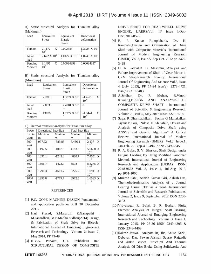
A) Static structural Analysis for Titanium alloy
(Maximum)
Load Equivalent
Stress
Equivalent
Elastic
Strain
Directional
deformation
Torsion 2.1172 X
108 0.002548 1.3924 X 10-
6
Axial
load
2.672 X 10⁶ 4.0127 X 10-
5 1.0249 X 10-
6
Bending
Moment
3.1495 X
107 0.00034898 0.00034387
B) Static structural Analysis for Titanium alloy
(Minimum)
Load Equivalent
Stress
Equivalent
Elastic
Strain
Directional
deformation
Torsion 7189.9 1.3874 X 10-
7 -1.4525 X
10-6
Axial
load
2.0336 2.4981 X 10-
11 0
Bending
Moment
13879 1.7277 X 10-
7 -4.3444 X
10-6
C) Thermal transient analysis for Titanium alloy
Powe
r ( in
watt)
Directional heat flux Total heat flux
Maximu
m
Minimu
m
Maximu
m
Minimu
m
500
watt
997.92 -889.83 3.486.2 2.137 X
10-6
600
watt
1197.5 -1067.8 4183.5 5.6608 X
10-7
700
watt
1397.1 -1245.8 4880.7 7.4551 X
10-7
800
watt
1596.7 -1423.7 5578 8.5275 X
10-7
900
watt
1796.3 -1601.7 6275.2 1.0911 X
10-6
1000
watt
1995.8 -1779.7 6972.5 1.0583 X
10-6
REFERENCES
[1] P.C. GOPE MACHINE DESIGN Fundamental
and application publisher PHI 30 December
2011.
[2] Hari Prasad, S.Marurthi, R.Ganapathi ,
M.Janardhan, M.P.Madhu sudhan(2014) Design
& Fabrication of Shaft Drive for Bicycle,
International Journal of Emerging Engineering
Research and Technology Volume 2, Issue 2,
May 2014, PP 43-49
[3] K.V.N. Parvathi, CH. Prabhakara Rao
STRUCTURAL DESIGN OF COMPOSITE
DRIVE SHAFT FOR REAR-WHEEL DRIVE
ENGINE, IJAERS/Vol. II/ Issue I/Oct.-
Dec.,2012/85-89
[4] R. P. Kumar Rompicharla, Dr. K.
Rambabu,Design and Optimization of Drive
Shaft with Composite Materials, International
Journal of Modern Engineering Research
(IJMER) Vol.2, Issue.5, Sep-Oct. 2012 pp-3422-
3428
[5] D. K. Padhal,D. B. Meshram, Analysis and
Failure Improvement of Shaft of Gear Motor in
CRM Shop,Research Inventy: International
Journal Of Engineering And Science Vol.3, Issue
4 (July 2013), PP 17-24 Issn(e): 2278-4721,
Issn(p):2319-6483
[6] A.Sridhar, Dr. R. Mohan, R.Vinoth
Kumar(),DESIGN AND ANALYSIS OF
COMPOSITE DRIVE SHAFT , International
Journal of Scientific & Engineering Research,
Volume 7, Issue 5, May-2016 ISSN 2229-5518
[7] Sagar R Dharmadhikari, Sachin G Mahakalkar,
Jayant P Giri, Nilesh D Khutafale, Design and
Analysis of Composite Drive Shaft using
ANSYS and Genetic Algorithm” A Critical
Review, International Journal of Modern
Engineering Research (IJMER) Vol.3, Issue.1,
Jan-Feb. 2013 pp-490-496 ISSN: 2249-6645
[8] R. A. Gujar, S. V. Bhaskar, Shaft Design under
Fatigue Loading By Using Modified Goodman
Method, International Journal of Engineering
Research and Applications (IJERA) ISSN:
2248-9622 Vol. 3, Issue 4, Jul-Aug 2013,
pp.1061-1066
[9] Mukesh Sahu, Ashish Kumar Giri, Ashish Das,
Thermohydrodynamic Analysis of a Journal
Bearing Using CFD as a Tool, International
Journal of Scientific and Research Publications,
Volume 2, Issue 9, September 2012 ISSN 2250-
3153
[10] Vidyasagar R. Bajaj, B. R. Borkar, Finite
Element Analysis of Integral Shaft Bearing,
International Journal of Emerging Engineering
Research and Technology Volume 3, Issue 1,
January 2015, PP 28-36 ISSN 2349-4395 &
ISSN 2349-4409
[11] Rakesh Jaiswal, Anupam Raj Jha, Anush Karki,
Debayan Das, Pawan Jaiswal, Saurav Rajgadia
and Ankit Basnet, Structural And Thermal
Analysis Of Disc Brake Using Solidworks And
© April 2018 | IJIRT | Volume 4 Issue 11 | ISSN: 2349-6002
IJIRT 146058 INTERNATIONAL JOURNAL OF INNOVATIVE RESEARCH IN TECHNOLOGY 1165
Ansys, International Journal of Mechanical
Engineering and Technology (IJMET) Volume
7, Issue 1, Jan-Feb 2016, pp. 67-77, Article ID:
IJMET_07_01_008
[12] CATIA user manual V5R20.
[13] ANSYS user manual 17.2