static coupling effect of a 2-degree-of-freedom direct ... · static coupling effect of a...
TRANSCRIPT

1
Static Coupling Effect of a 2-Degree-of-Freedom Direct Drive Induction Motor Jikai Si1*, Lujia Xie1, Xiaozhuo Xu1, Yifeng Zhu1, Wenping Cao2
1 School of Electrical Engineering and Automation, Henan Polytechnic University, Jiaozuo
Henan, China 2School of Engineering and Applied Science, Aston University, Birmingham, U.K. *[email protected]
Abstract: Two-degree-of-freedom motors are capable of producing linear, rotary, and helical motion, and
thus have widespread applications in special industries. In this paper, a new concept—static coupling
effect—is studied in the 2-degree-of-freedom direct drive induction motor (2DoFDDIM). The proposed
approach is based on the image method and the 3D finite element method. The image method model is
established to analyse its reasons and predict the main effects, which are then verified by the proposed 3D
finite element static coupling model and experiments. The induced voltages and currents are produced in
the static part and induced torque or force is obtained, even though the static part is not energized. It is
concluded that the static coupling effect increases with the supply frequency and is influenced by the stator
winding configuration. Thus, the existence of the static coupling effect is confirmed, which must be taken
into account in future optimization and precise control of the 2DoFDDIM.
Index Terms: induction motor, image method, static coupling effect, 3D finite element method, 2-degree-
of-freedom.
1. Introduction
In conventional electrical machinery, 2-degree-of-freedom (2DoF) motion is achieved by a rotary
motor installed on a linear motor. In this manner, the system is heavy and requires more space as well as
additional losses caused by the intermediate transmission mechanism. Therefore, the drive system will be
miniaturised and be more cost-effective if this 2DoF motion is performed by a single motor. 2DoF motors
are capable of rotary, linear, and helical motion. These motors have the advantages of an integrated
structure, small mechanical loss, high reliability, and low cost. Therefore, they are of great interest and
have widespread industrial applications, such as boring machines, mechanical drills, and electric vehicles
[1-2]. However, owing to the special structure and the motion with two degrees of mechanical freedom,
the inner electromagnetic field is complicated and the coupling effect must be taken into consideration.
A direct-drive rotary-linear electromechanical actuation system for control of gearshifts in
automated transmissions was developed [3]. Helical motion is produced by the direct coupling of the
direct-drive rotary actuator and the shaft of the linear actuator. There is no electromagnetic coupling effect
between the two stators because of the interface plate and a sufficiently large separation distance.
Reference [4] investigated a linear-rotary permanent-magnet motor and the two-directional d-q
transformation was proposed to decouple the inter-relationship between linear and rotary motion [5]. A
decoupling motion control algorithm based on a torque and force distribution function was proposed to
This paper is a postprint of a paper submitted to and accepted by IET Electric Power Applications and it is subject to Institution of Engineering and Technology Copyright. The copy of record is available at the IET Digital Library.

2
achieve decoupled control of the rotary–linear switched reluctance motor [6]. Reference [7] developed an
equivalent 2D model to analyse a 2DoF rotary-linear actuator. A new checkerboard magnetization pattern
was applied to produce the decoupled torque and force. Although 2DoF motors have been developed over
the years and several decoupled control strategies were presented [8-11], their inner-coupling field is still
not well understood.
Ebrahim Amiri proposed a rotary-linear induction motor with twin armature [12]. The motor, in its
operation, can be regarded as a set of two independent motors, namely, a conventional rotary and a tubular
linear motor with the rotors joined rigidly, in which the coupling effect was caused by dynamic end effect.
The transient time-domain finite element model and frequency-domain slip frequency technique were
combined to analyse the dynamic end effect generated by linear motion on both linear and rotary
armatures [13]. The equivalent circuit model of the motor was proposed, which took into account the static
end effect in the linear armature and the dynamic longitudinal end effects occurring at both rotary and
linear armatures during the helical and linear motion [14]. The 2DoF direct drive induction motor
(2DoFDDIM) is another 2DoF induction motor in which the stator is composed by two arc-shaped stators
[15]. There is also coupling effect involved [16].
The coupling effect of the 2DoFDDIM is separated into two categories according to whether the
rotary and linear parts are powered or not, namely, the static coupling effect and the coupling effect of
motion. The former is under the condition of only one part being powered, and the latter is derived when
both parts are powered. In this paper, only the static coupling effect is researched, while the coupling
effect of motion will be studied in its companion paper. The analysis of the static coupling effect is carried
out by the special image method model and 3D finite element coupling effect model. Based on a constant
voltage to frequency ratio, the static coupling effect is analysed in terms of induced voltage, induced
current, and torque. Testing is also carried out to verify the special static coupling effect.
2. Structure and Principles of Operation
A 2DoFDDIM consists of an arc-shaped stator of the rotary part (SR), an arc-shaped stator of the
linear part (SL), and a solid rotor coated with a copper layer. The SR is composed of a stator core slotted
along the axial direction where the stator windings are accommodated. The SL also has a stator core but is
slotted along the circumferential direction for windings. The two stators are assembled orthogonally into a
whole stator and share a cylindrical rotor, as shown in Fig. 1. The main structure parameters are listed in
Table 1.

3
(a) (b)
(c) (d)
(e) (f)
Fig. 1. Structure of the 2DoFDDIM
(a) Rotary motion arc-shaped stator. (b) Linear motion arc-shaped stator.
(c) Integrated stator. (d) Rotor. (e) Assembly of the 2DoFDDIM. (f) Prototype of the 2DoFDDIM.
Table 1 Structure parameters of the 2DoFDDIM
Item Values/ Dimension
Rotary Part Linear Part
Rated voltage (UN) 220 V(Y) 220 V(Y)
Pole pair (p) 2 2
Stator inner diameter 98 mm 98 mm
Stator outer diameter 155 mm 155 mm
Stator axial length 135 mm 156 mm
Air-gap thickness 1 mm 1 mm
Slot number 12 12
Number of wires per slot 65 65
Wire diameter 0.56 mm 0.56 mm
Thickness of copper layer 1.5 mm 1.5 mm
Thickness of steel layer 7 mm 7 mm
When the SR is energized, a rotating magnetic field is generated. According to the electromagnetic
induction principal, an electromagnetic force (EMF) is induced on the rotor conductor, producing an
electromagnetic torque. In a similar manner, a traveling wave magnetic field will be generated when the
SL is powered and the linear force will follow. If only SR or SL are energized, the motor will do single-
degree mechanical motion. When both of them are energized, the motor produces a helical motion.

4
3. Static coupling effect
Fig. 2 shows the 3D finite element model of the 2DoFDDIM. It is worth noting that the SR and SL
can be transformed equivalently to each other [15], as shown in Fig. 3. Therefore, this study focuses on the
static coupling effect of the rotary part produced by linear motion, which is also applicable to the opposite
scenario caused by rotary motion. The SL is energized by a 180 V, 10 Hz AC source, and the rotary
windings are non-powered. The distributions of magnetic flux density when linear slip is 0 and 1 are
shown in Fig. 4. It is viewed along the radial direction (x-x’), as depicted in Fig. 2.
XX’
ShellRotory stator
Linear statorCopper layer
Steel layer
Fig. 2. 3D finite element model of the 2DoFDDIM
Linear statorEquivalent plane
model Rotary stator
Fig. 3. Equivalent transformation of the 2DoFDDIM
Rotary stator
Linear stator
Rotor
(a) linear slip=0
5
Rotary stator
Linear stator
Rotor
(b) linear slip=1
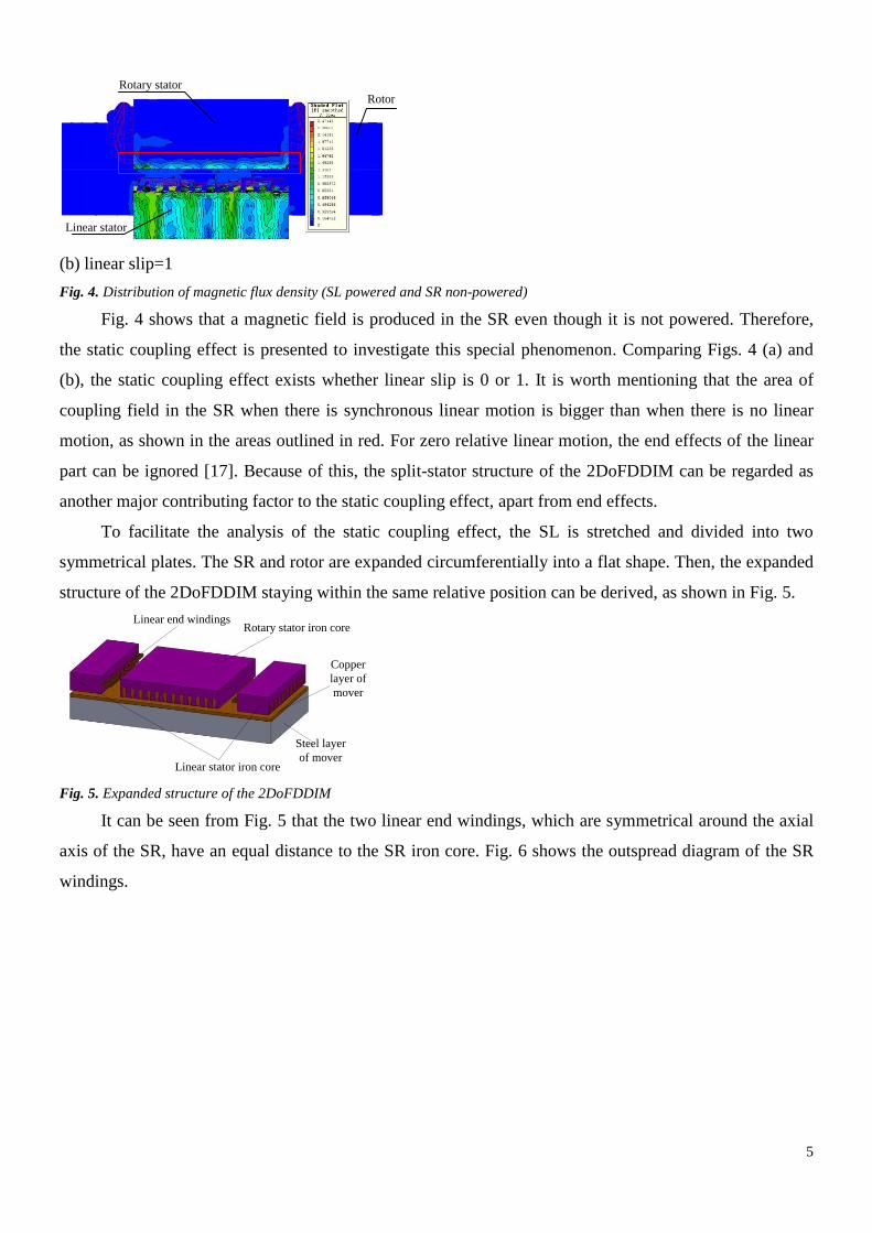
Fig. 4. Distribution of magnetic flux density (SL powered and SR non-powered)
Fig. 4 shows that a magnetic field is produced in the SR even though it is not powered. Therefore,
the static coupling effect is presented to investigate this special phenomenon. Comparing Figs. 4 (a) and
(b), the static coupling effect exists whether linear slip is 0 or 1. It is worth mentioning that the area of
coupling field in the SR when there is synchronous linear motion is bigger than when there is no linear
motion, as shown in the areas outlined in red. For zero relative linear motion, the end effects of the linear
part can be ignored [17]. Because of this, the split-stator structure of the 2DoFDDIM can be regarded as
another major contributing factor to the static coupling effect, apart from end effects.
To facilitate the analysis of the static coupling effect, the SL is stretched and divided into two
symmetrical plates. The SR and rotor are expanded circumferentially into a flat shape. Then, the expanded
structure of the 2DoFDDIM staying within the same relative position can be derived, as shown in Fig. 5.
Rotary stator iron core
Linear stator iron core
Linear end windings
Copper
layer of
mover
Steel layer
of mover
Fig. 5. Expanded structure of the 2DoFDDIM
It can be seen from Fig. 5 that the two linear end windings, which are symmetrical around the axial
axis of the SR, have an equal distance to the SR iron core. Fig. 6 shows the outspread diagram of the SR
windings.

6
1 42 53 6 7 108 119 12
A C B a c b
Fig. 6. Outspread diagram of the SR windings
The image method is commonly used for analysing boundary problems of electromagnetic fields
since the method provides certain solution forms for some important problems involving straight-line,
circular, and spherical boundaries in a simple manner, which decrease the need for formal solutions of
Laplace's and Poisson's equations [18]. Therefore, it is applied here to analyse the static coupling effect in
the 2DoFDDIM qualitatively. In order to simplify the analytical model, some assumptions are made.
(1) The permeability of the entire iron core of the stator is μ2, and that of the inner space region
between SL and SR is μ1 (namely, the permeability of air).
(2) The end-winding effect is ignored. The active side of the coil is infinite and the current passing
through it is line current.
(3) The displacement current and higher harmonics are ignored and the electromagnetic field is
assumed to be linear.
Because the rotor is non-powered and acts as a symmetrical geometry with isotropic magnetic
medium, only the magnitude of the induced magnetic field in the SR is influenced by its induced eddy
current. Therefore, the proportional relationship of the induced magnetic fields among the 3-phase SR
windings remains the same regardless of the eddy current. To simplify the analysis, the image method
model ignoring induced eddy current in the rotor is developed, which is available to analyse the static
coupling effect qualitatively, as shown in Fig. 7. The permeabilities of areas 1 and 2 are μ1 and μ2,
respectively. i, as the original image current, is the end-winding current that is parallel to the rotational
axis. The left and right sides of the SR, namely, x1 and x2, are the imaging planes. A, B, and C represent
the 3-phase SR windings.

7
·
x1 x2
y1y2
A C B A C BA C BA C Bi i
i' i'
Original current Original current
Imaging
current
h h
h h
Rotary
stator
iron core
Equivalent centre
point
Rotary stator
slot, which is
equivalent to
the centre
point. Area 1
Area 2
Area 1
Fig. 7. Image method model
According to assumption (1), the total magnetic flux density in the SR slot is equivalent to that at the
centre point of the stator slot. y1 is the distance between two adjacent centre points, )( ZDy t 2/1 , where
Dt is the inner diameter of the stator and Z is the number of stator slots. On the basis of symmetrical SL
end windings, the double coordinate system is established. According to the image method principle [19],
if the material with permeability μ2 is replaced by the material with μ1, the entire field problem is reduced
to one of integration. It is recognized that the whole space (both areas 1 and 2) is composed of a
homogeneous medium whose permeability is μ2. The virtual synthetic current i’ is used to substitute the
original current when calculating the magnetic flux density of area 2. The position of substitute current i’
remains the same as the one of original current i.
ii21
12
(1)
The magnetic vector potential of area 2 (y<0) can be derived in (2).
22
21
122 )(ln
2
4hyx
iAz
(2)
Then, the magnetic flux density at every point in area 2 can be obtained from (3).
x
AB
y
AB
zy
zx
2
2
(3)
The magnetic flux density in the A-phase windings of the SR, produced by the current through left and
right SL end windings, respectively, are given as (4)–(5).

8
)92/
2
62/
2
32/
2
2/
2(
2
4
0
11
1111
121
12
hyy
hyyhyy
hy
iB
B
lxA
lyA
(4)
)112/
2
82/
2
52/
2
22/
2(
2
4
0
11
1111
1121
12
hyy
hyyhyy
hyy
iB
B
rxA
ryA
(5)
In a similar manner, the magnetic flux density in the B-phase windings of the SR can be derived from (6).
lxArxB
ryB
rxAlxB
lyB
BB
B
BB
B 00 (6)
Then it can be concluded from (4)–(6):
0yBryAlyAyA
xBrxAlxAxA
BBBB
BBBB (7)
The induced magnetic field generated in the SR windings changes with the SL current, which
produces alternating current in the 3-phase SR windings. The frequency of the induced alternating current
is equal to the one of the SL current. According to Maxwell’s equation,t
BE
, it can be determined
that the induced voltages generated in the 3-phase SR windings are equivalent. On the basis of constant
voltage and frequency ratio, the linear current frequency increases with linear power frequency; then, the
induced voltage in the SR will follow. Based on (7) and Ampere’s Circuital Law, NIdlB
2
, taking the
same closed path, the SR currents in A-phase and B-phase windings have equal value and phase, namely,
IA = IB. The SR windings are not powered and form a closed circuit. It follows from the Kirchhoff’s Law
that the value of C-phase SR current is the double of A-phase current, namely, IC = 2IA, but the phase is
opposite to it. Owing to the unbalanced SR current derived above, the fluctuating torque will then be
generated.

9
Through the above analysis, it can be seen that, because of the static coupling effect, there are
currents and voltages in the SR windings, although the SR is not powered. The quantitative analysis is
carried out by 3D finite element method (FEM).
4. 3D-FEM Simulation
Modelling static coupling effects is a significant challenge as it combines the linear part and rotary
part at the same time. Besides, static coupling effect is an abstract concept, so it is not easy to analyse
quantitatively. To overcome these difficulties, the induced voltages and induced currents developed in the
stator of the non-powered part and the variation of induced torque (force) are used to characterise it. For
the static coupling effect in the SR produced by linear motion, the 3D-FEM coupling model (zero linear
speed) of the 2DoFDDIM is established and the following algorithm is proposed to model the static
coupling effect.
Condition (1): In order to derive the induced voltages in the non-powered SR produced by the static
coupling effect, the SR windings are opened in the 3D-FEM coupling model while the SL windings are
powered with 3-phase sinusoidal power.
Condition (2): In order to analyse the induced currents in the SR windings caused by the static
coupling effect, the non-powered SR windings need to be shorted to provide current paths while the SL
windings are also powered with 3-phase sinusoidal power.
Condition (3): The rotary electromagnetic torque produced by the static coupling effect is obtained
under the condition shown in Condition (2).
It is worth noting that the selection of zero linear speed (linear slip s = 1) is arbitrary and the
conditions remain the same for all other linear speeds.
Based on a constant voltage/frequency ratio, the 3D-FEM coupling model is powered with LC50Hz,
LC40Hz, LC30Hz, LC20Hz, and LC10Hz, in which L means only the SL windings are powered and C
shows that the SR windings are opened (namely, under condition (1)). The induced voltages produced in
the SR windings are shown in Fig. 8. The related data are listed in Table 2 and Table 3.
0 50 100 150 200 250 300
-0.4
-0.2
0.0
0.2
0.4
Vo
ltag
e (V
)
Time (ms)
A
B
C
0 20 40 60 80 100
-1.0
-0.5
0.0
0.5
1.0
Volt
age
(V)
Time (ms)
A
B
C

10
(a) (b)
0 20 40 60 80 100-2.0
-1.5
-1.0
-0.5
0.0
0.5
1.0
1.5
2.0
Volt
age
(V)
Time (ms)
A
B
C
0 20 40 60 80 100-3
-2
-1
0
1
2
3
Vo
ltag
e (V
)
Time (ms)
A
B
C
(c) (d)
0 20 40 60 80 100
-3
-2
-1
0
1
2
3
Vo
ltag
e (V
)
Time (ms)
A
B
C
(e)
Fig. 8. Induced voltages of the SR windings (s = 1, Voltage/Frequency = const.)
(a)LC10Hz (b)LC20Hz (c)LC30Hz (d)LC40Hz (e)LC50Hz
Table 2 Effective values of induced voltages of the SR windings (s = 1, voltage/frequency = const.)
f [Hz]
Effective values [V] Maximum
difference
ΔU [V]
ΔU/UA UA UB UC
10 0.29 0.29 0.28 0.01 3.44%
20 0.74 0.72 0.73 0.02 2.70%
30 1.19 1.18 1.19 0.01 0.84%
40 1.54 1.53 1.53 0.01 0.65%
50 1.83 1.85 1.86 0.03 1.64%
Table 3 Phases of induced voltages of the SR windings (s = 1, voltage/frequency = const.)
f [Hz] Phase φ [°]
Phase difference
Δφ [°]
φA φB φC |φA−φB| |φA−φC|
10 189.05 188.72 0.83 0.33 188.22
20 157.88 156.53 321.43 1.35 163.55
30 136.98 137.78 294.13 0.8 157.15
40 116.95 116.46 268.69 0.49 151.74
50 102.64 100.14 248.29 2.5 145.65

11
It can be seen from Fig. 8, Table 2, and Table 3 that there are induced voltages in the 3-phase SR
windings generated by the static coupling effect, even though the SR is not powered. Based on a constant
voltage and frequency ratio, the values of induced voltages increase, but their phases decrease with the
growth of source frequency. It should be noted that the maximum difference ΔU of 3-phase induced
voltages is not greater than 0.03 V, and ΔU/UA is less than 3.44%, which is satisfied with Maxwell’s
equation. The phase difference of induced voltages between A-phase and B-phase |φA−φB| is not beyond
2.5°, whereas the phase difference between A-phase and C-phase |φA-φC| is larger and decreases with the
increase of source frequency. The cause of such phenomenon is mainly due to the spatial distribution of
the 3-phase SR windings, which is shown in Fig. 5 and Fig. 6.
Based on a constant voltage and frequency ratio, the 3D-FEM coupling model is powered with
LS50Hz, LS40Hz, LS30Hz, LS20Hz, and LS10Hz, where L means only SL windings are powered and S
shows that the SR windings are shorted (namely, under condition (2)). The induced currents produced in
the SR windings are shown in Fig. 9. The related data are listed in Table 4 and Table 5.
0 50 100 150 200 250 300
-0.4
-0.3
-0.2
-0.1
0.0
0.1
0.2
0.3
0.4
Cu
rren
t (A
)
Time (ms)
A
B
C
0 20 40 60 80 100 120 140 160
-0.6
-0.4
-0.2
0.0
0.2
0.4
0.6
Curr
ent
(A)
Time (ms)
A
B
C
(a) (b)
0 20 40 60 80 100 120 140 160
-0.9
-0.6
-0.3
0.0
0.3
0.6
0.9
Cu
rren
t (A
)
Time (ms)
A
B
C
0 20 40 60 80 100-0.9
-0.6
-0.3
0.0
0.3
0.6
0.9
Cu
rren
t (A
)
Time (ms)
A
B
C
(c) (d)

12
0 20 40 60 80 100
-0.8
-0.4
0.0
0.4
0.8
Curr
ent
(A)
Time (ms)
A
B
C
(e)
Fig. 9. Induced currents of the SR windings (s = 1, Voltage/Frequency = const.)
(a)LS10Hz (b)LS20Hz (c)LS30Hz (d)LS40Hz (e)LS50Hz
Table 4 Effective values of induced currents of the SR windings (s = 1, voltage/frequency = const.)
f [Hz] Effective values [A]
Difference
ΔI [A]
IA IB IC |IA−IB| |IA−IC|
10 0.14 0.12 0.27 0.02 0.13
20 0.24 0.21 0.45 0.02 0.21
30 0.28 0.25 0.54 0.03 0.25
40 0.39 0.26 0.57 0.03 0.27
50 0.30 0.27 0.57 0.03 0.28
Table 5 Phases of induced currents of the SR windings (s = 1, voltage/frequency = const.)
f [Hz] Phase φ [°] Phase differenceΔφ [°]
φA φB φC |φA−φB| |φA−φC|
10 326.19 327.30 146.70 1.11 179.49
20 297.46 296.92 117.21 0.54 180.25
30 88.47 85.85 267.25 2.62 178.78
40 250.18 245.64 68.06 4.54 182.12
50 236.33 230.76 53.73 5.57 182.6
It can be seen from Fig. 9, Table 4, and Table 5 that there are induced currents in the 3-phase SR
windings generated by the static coupling effect, even though only the SL is powered. Based on a constant
voltage and frequency ratio, the values of rotary-induced currents increase with the growth of source
frequency. By comparison, the value of A-phase induced current IA is approximately equal to B-phase IB
with a maximum difference of 0.03 A, and the phase difference |φA−φB| is less than 5.57°. The difference of
the induced current values between A-phase, IA, and C-phase, IC, increases with source frequency, but IC
remains nearly twice the value of IA. It should also be noted that the phase difference between A-phase and
C-phase |φA−φC| is about 180°, which is explained by Ampere’s ciruital law and Kirchoff’s voltage law.
Fig. 10 and Table 6 show the induced rotary electromagnetic torque of the rotor when the 3D-FEM
coupling model is powered with LS50Hz, LS40Hz, LS30Hz, LS20Hz, and LS10Hz (namely, under
condition (3)).

13
0 20 40 60 80 100
-0.10
-0.05
0.00
0.05
0.10
0.15
To
rqu
e (N
m)
Time (ms)
LS10Hz
LS20Hz
LS30Hz
LS40Hz
LS50Hz
Fig. 10. Induced rotary torque (s = 1, voltage/frequency = const.)
Table 6 Induced rotary torque (s = 1, voltage/frequency = const.)
f [Hz] 10 20 30 40 50
Maximum/N 0.01 0.04 0.07 0.10 0.11
It can be seen from Fig. 10 and Table 6 that there is a rotary torque on the rotor when only the SL is
powered. Because of the unbalanced induced coupling currents in the 3-phase SR windings, the rotary
torque fluctuates irregularly on a large scale, which coincides with the analysis applying image method.
Based on a constant voltage and frequency ratio, the fluctuation is heightened when the source frequency
increases, which gives the enhancement of the static coupling effect.
For other linear speeds, there are also induced voltages and induced currents in the SR windings, as
well as induced torque when only the SL is powered, as shown in Fig. 11, Fig. 12, and Fig. 13. The related
data are shown in Table 7.
0.0 0.2 0.4 0.6 0.8 1.01.80
1.85
1.90
1.95
2.00
Volt
age
(V)
slip
A
B
C
Fig. 11. Induced voltages of the SR windings vs. slip (LC50Hz)

14
0.0 0.2 0.4 0.6 0.8 1.00.0
0.2
0.4
0.6
0.8
1.0
Cu
rren
t (A
)
Slip
A
B
C
Fig. 12. Induced currents of the SR windings vs. slip (LS20Hz)
0.0 0.2 0.4 0.6 0.8 1.00.00
0.02
0.04
0.06
0.08
0.10
Torq
ue
(Nm
)
Slip
Torque
Fig. 13. Induced rotary torque vs. slip (LS20Hz)
Table 7 Related data vs. slip
Slip
Induced voltages [V]
(LC50Hz)
Induced currents [V]
(LS20Hz) Torque [Nm]
(LS20Hz) UA UB UC IA IB IC
0 1.92 1.87 1.94 0.37 0.33 0.70 0.05
0.2 1.88 1.87 1.92 0.37 0.33 0.70 0.04
0.4 1.88 1.87 1.91 0.37 0.32 0.69 0.04
0.6 1.87 1.86 1.90 0.36 0.32 0.68 0.03
0.8 1.87 1.85 1.88 0.36 0.31 0.67 0.03
1 1.85 1.83 1.86 0.34 0.30 0.64 0.03
It can be seen from Fig. 11, Fig. 12, Fig. 13, and Table 7 that induced voltages and induced currents
agree well at any operational linear slip. In addition, the values of induced voltages, induced currents, and
induced rotary torque decrease slightly with the increase of slip. It is because of this that the end effects of
the linear part are one of the causes of the static coupling effect; therefore, the less end effects, the smaller
the static coupling effect. However, the split-stator structure of the 2DoFDDIM is the major contributing
factor, so the induced voltages (take the LC50Hz as an example) and induced currents (take the LS20Hz as
an example) under zero linear speed only decrease by 3.3% and 8.6%, respectively, compared with those
under synchronous linear velocity.
CBA
CBA
III
UUU
5.0 (8)

15
Similarly, the same program can be used to analyse the static coupling effect in the linear part
produced by rotary motion. The results are listed in Table 8, Table 9, and Table 10.
Table 8 Effective values of induced voltages of the SL windings (s = 1, voltage/frequency = const.)
f [Hz]
Effective values [V] Maximum
difference
ΔU [V]
ΔU/UU UU UV UW
10 0.22 0.22 0.23 0.01 4.54%
20 0.65 0.62 0.65 0.03 4.61%
30 1.13 1.14 1.18 0.05 4.42%
40 1.69 1.65 1.71 0.06 3.55%
50 2.30 2.29 2.37 0.08 3.48%
Table 9 Effective values of induced currents of the SL windings (s = 1, voltage/frequency = const.)
f [Hz] Effective values [A]
Difference
ΔI [A]
IU IV IW |IU−IV| |IU−IW|
10 0.127 0.125 0.252 0.002 0.125
20 0.241 0.238 0.479 0.003 0.238
30 0.281 0.298 0.577 0.017 0.296
40 0.389 0.387 0.772 0.002 0.383
50 0.451 0.449 0.901 0.002 0.45
Table 10 Effective values of induced currents of the SL windings (s = 1, voltage/frequency = const.)
f [Hz] 10 20 30 40 50
Maximum/N 0.14 0.47 1.10 1.38 1.49
As shown in Table 8, Table 9, and Table 10, the static coupling effect in the SL produced by
rotary motion is also enhanced with the increase of supply frequency of the rotary part. Moreover, the
3-phase induced voltages and induced currents in the SL have the same proportional relationship as
(8), namely
WVU
WVU
III
UUU
5.0, which is determined by the stator winding structure of the 2DoFDDIM.
5. Experiment Validation
A test rig is set up and experimental tests are carried out on the prototype of the motor shown in Fig.
14. The laboratory model of the 2DoFDDIM has a relatively short secondary length. Therefore, it is
technically difficult to measure motor performance at linear speeds greater than zero, so the test is
performed only at zero linear speed.

16
Fig. 14. Photograph of the testing platform system for the 2DoFDDIM
In order to quantify the static coupling effect, the SR is not powered, which means the SR windings
are opened, then rotary induced voltages (RMS) produced by linear motion can be tested, as listed in Table
11. The comparison of the FEM analysis and test results is shown in Fig. 15. It can be seen from Table 2,
Table 11, and Fig. 15 that the test results coincide well with those of the FEM analysis, which validates the
simulation models.
Table 11 Induced voltage of experimental testing (zero linear speed, voltage/frequency = const.)
f [Hz]
Effective values [V] Maximum
difference
ΔU [V]
ΔU/UA UA UB UC
10 0.26 0.27 0.27 0.01 3.85%
20 0.67 0.68 0.68 0.01 1.49%
30 1.09 1.11 1.13 0.04 3.67%
40 1.36 1.39 1.41 0.05 3.67%
50 1.65 1.67 1.7 0.05 3.03%
10 20 30 40 50
0.2
0.4
0.6
0.8
1.0
1.2
1.4
1.6
1.8
2.0
30 40
1.0
1.2
1.4
1.6
Ind
uc
ed
Vo
lta
ge
(V
)
Frequency (H z)
Ind
uce
d V
olt
age
(V)
Frequency (Hz)
UA-FEM
UB-FEM
UC-FEM
UA-Test
UB-Test
UC-Test
Fig. 15. Induced voltage of experimental testing and FEM analysis (zero linear speed, voltage/frequency = const.)
6. Conclusion
This paper presented a study of the coupling fields in 2DoFDDIM with a focus on the static coupling
effect. The image method model and 3D finite element model are established to analyse its cause and

17
impact. Because of the static coupling effect, an EMF voltage is generated in the static part as well as an
electromagnetic torque (or force). From this study, A-phase (U-phase) induced current is equal to that in
B-phase (V-phase), which is half of that in C-phase (W-phase). The static coupling effect increases with
the supply frequency, which must be taken into account to realize precise control of the 2DoFDDIM.
Besides, it is found that the static coupling effect is closely associated with the special split structure of the
2DoFDDIM. The experimental results have validated the developed models and simulation results so that
the proposed methodologies are shown to be effective in analysing such a complex concept in the
2DoFDDIM.
7. Acknowledgments
This work is supported by National Natural Science Foundation of China under grant 51277054,
Project of Key Scientific and Technological Research in Henan Province 152102210101, Henan
Polytechnic University Innovation Team T2015-2, and Henan Polytechnic University Middle-Young Age
Top-Notch Innovative Personnel HPUSEEA-001.
8. References
[1] Li, S. Y., and Cheng, K. W.: 'A New Two-degree of Freedom Switched Reluctance Motor for Electric Vessel',
6th International Conference on Power Electronics Systems and Applications (PESA), Hong Kong, 2015, pp.
1–6.
[2] Fleszar J., and Mendrela, E.: 'Twin-armature rotary-linear induction motor', IEE Proceedings B Electric Power
Applications, 1983, 130, (3), pp. 186.
[3] Turner, A., Ramsay, K., Clark, R., and David H.: 'Direct-Drive Rotary-Linear Electromechanical Actuation
System for Control of Gearshifts in Automated Transmissions', 2007 IEEE Vehicle Power and Propulsion
Conference, Arlington, TX, 2007, pp. 267–272.
[4] Jin, P., Fang, S., and Lin, H., et al.: 'Analytical Magnetic Field Analysis and Prediction of Cogging Force and
Torque of a Linear and Rotary Permanent Magnet Actuator', IEEE Transactions on Magnetics, 2011, 47, (10),
pp. 3004–3007.
[5] Jin, P., Lin, H., Fang, S., and Ho, S. L.: 'Decoupling Control of Linear and Rotary Permanent Magnet Actuator
Using Two-Directional - Transformation', IEEE Transactions on Magnetics, 2012, 48, (10), pp. 2585–2591.
[6] Pan, J., Meng, F., and Cao G.: 'Decoupled control for integrated rotary – linear switched reluctance motor', IET
Electric Power Applications, 2014, 8, (5), pp. 199–208.
[7] Meessen, K. J., Paulides, J. J. H., and Lomonova, E. A.: 'Analysis of a Novel Magnetization Pattern for 2-DoF
Rotary-Linear Actuators', IEEE Transactions on Magnetics, 2012, 48, (11), pp. 3867–3870.

18
[8] Xu, L., Lin, M., Fu, X., and Li, N.: 'Analysis of a Double Stator Linear Rotary Permanent Magnet Motor With
Orthogonally Arrayed Permanent Magnets', IEEE Transactions on Magnetics, 2016, 52, (7), pp. 1–4.
[9] Caruso, M., Cecconi, V., and Di Dio, V., et al.: 'Speed Control of a Two-Degree of Freedom Induction Motor
with Rotor Helical Motion for Industrial Applications', Annual Conference - From Research to Industry,
Trieste, Italy, 2014, pp. 1–6.
[10] Szabo, L., Bentia, I., and Ruba, M.: 'A Rotary-Linear Switched Reluctance Motor for Automotive Applications',
20th International Conference on Electrical Machines, Marseille, 2012, pp. 2615–2621.
[11] Ioana, B., Lorand, S., and Mircea, R.: 'A Novel Rotary-Linear Switched Reluctance Motor', Journal of
Computer Science and Control Systems, 2012, 1, (5), pp. 13–16.
[12] Amiri, E., Gottipati, P., and Mendrela, E. A.: '3-D Space Modeling of Rotary-Linear Induction Motor with
Twin-Armature', 1st International Conference on Electrical Energy Systems (ICEES), USA, 2011, pp. 203–206.
[13] Amiri, E., Jagiela, M., Dobzhanski, O., and Mendrela, E.: 'Modeling Dynamic End Effects in Rotary Armature
of Rotary-Linear Induction Motor', IEEE International Electric Machines & Drives Conference (IEMDC), 2013,
pp. 1088–1091.
[14] Amiri, E.: 'Circuit Modeling of Double-Armature Rotary- Linear Induction Motor', 39th Annual Conference of
the IEEE Industrial Electronics, USA, 2014, pp. 431–436.
[15] J. Si, H. Feng, L. Ai, Y. Hu and W. Cao: 'Design and Analysis of a 2-DOF Split-Stator Induction Motor', IEEE
Transactions on Energy Conversion, 2015, 30, (3), pp. 1200–1208.
[16] Si, J., Ai, L., Feng, H., Zhu, Y., and Hu Y.: 'Analysis on Coupling Effect of 2-DOF Direct Drive Induction
Motor Based on 3-D Model', 17th International Conference on Electrical Machines and Systems (ICEMS),
Hangzhou, 2014, pp. 1157–1163.
[17] Anand, M., and Ashok, S.: 'Modelling of a Linear Induction Motor for Automated Material Handling
Application', International Conference on Sustainable Energy and Intelligent Systems, Chennai, 2011, pp. 661–
665.
[18] Son, H., Lee, K., Song, J. Y., and Park, J.: 'Effects of Magnetic Conducting Boundary on Design of
Electromagnetic Actuators Using Image method', International Conference on Smart Manufacturing
Application, ICSMA, Gyeonggi-do, 2008, pp. 172–177.
[19] Yunqiu, T., and Yanping, L.: 'Analysis and calculation of motor electromagnetic field (in Chinese)', Beijing:
China Machine Press, 2010, pp. 27–35