status of fast reactor and pyroprocess technology
TRANSCRIPT
1 FR09, Kyoto, 7-11 December 2009 Ministry of Education, Ministry of Education, Science and TechnologyScience and Technology
Status of Fast Reactor and Pyroprocess Technology Development in Korea
Ministry of Education, Science and TechnologyMinistry of Education, Science and Technology
International Conference on Fast Reactors and Related Fuel Cycles (FR09), Kyoto, Japan
7 December 2009
Jong-Bae CHOI

2 FR09, Kyoto, 7-11 December 2009 Ministry of Education, Ministry of Education, Science and TechnologyScience and Technology
Outline
Korean Nuclear Power ProgramISFR & Pyroprocess Development ProgramIISFR Technology DevelopmentIIIPyroprocess Technology DevelopmentIVSummaryV
3 FR09, Kyoto, 7-11 December 2009 Ministry of Education, Ministry of Education, Science and TechnologyScience and Technology
Korean Nuclear Power ProgramI
I.1 Current Status of NPPsI.2 Status of Spent Fuel StorageI.3 Radioactive Waste Management LawI.4 Reactor Transition Scenario
4 FR09, Kyoto, 7-11 December 2009 Ministry of Education, Ministry of Education, Science and TechnologyScience and Technology
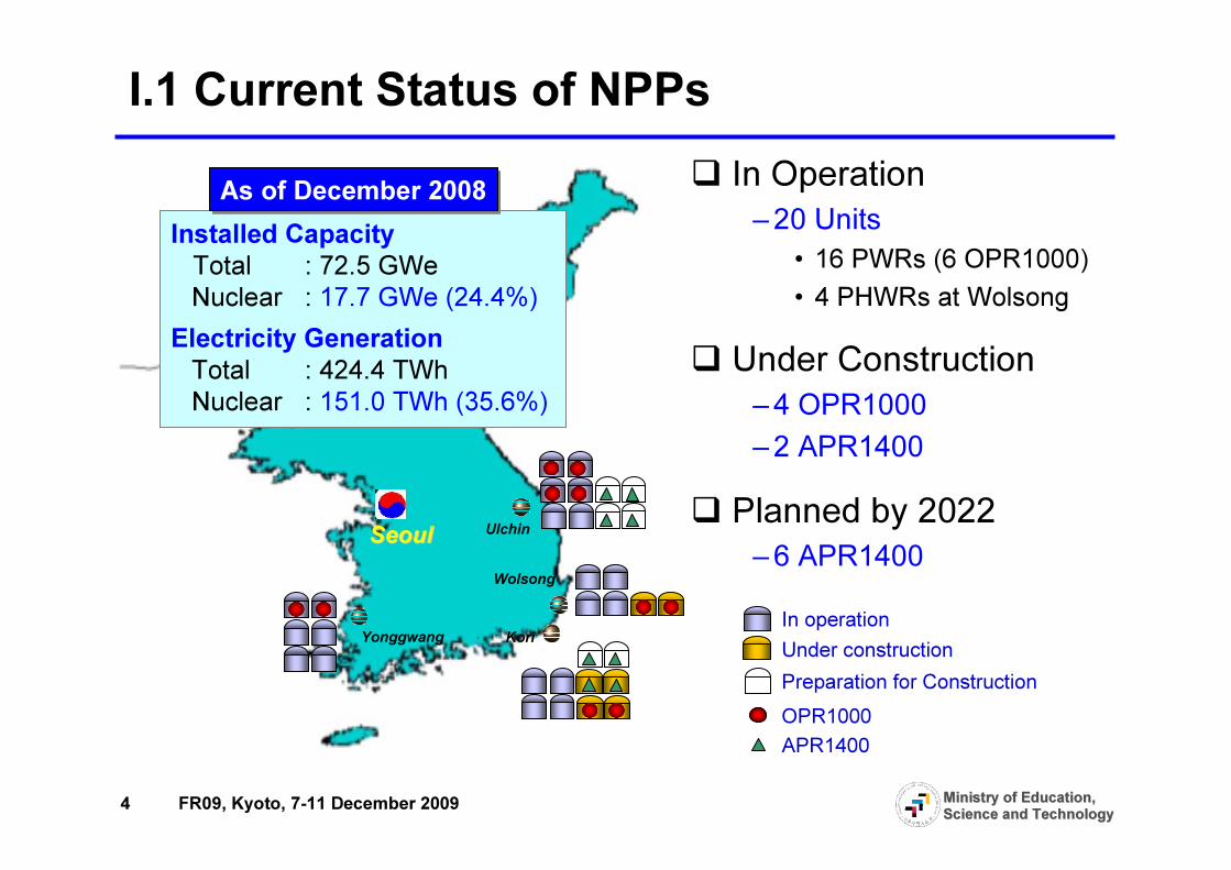
I.1 Current Status of NPPs
SeoulSeoul
Kori
Ulchin
Wolsong
Yonggwang
Installed CapacityTotal : 72.5 GWeNuclear : 17.7 GWe (24.4%)
Electricity GenerationTotal : 424.4 TWhNuclear : 151.0 TWh (35.6%)
As of December 2008As of December 2008 � In Operation–20 Units
• 16 PWRs (6 OPR1000)• 4 PHWRs at Wolsong
� Under Construction–4 OPR1000–2 APR1400
� Planned by 2022–6 APR1400
Under constructionIn operation
Preparation for ConstructionOPR1000APR1400

5 FR09, Kyoto, 7-11 December 2009 Ministry of Education, Ministry of Education, Science and TechnologyScience and Technology
I.2 Status of Spent Fuel Storage
NPPSites
Kori
Yonggwang
Ulchin
Wolsong
Total
Storage Capacity(MTU)2,253
2,686
2,328
5,980
13,247
CumulativeAmount(MTU)1,685
1,623
1,294
5,481
10,083
Year of Saturation
2016
2016
2017
2009
As of December 2008Storage Capacity(MTU) 2,253
3,528
2,328
9,155
17,262
Year of Saturation
Expansion Plan
2016
2021
2017
2017
� On-site SF storage limit will be reached from 2016� Decision making process for interim SF storage

6 FR09, Kyoto, 7-11 December 2009 Ministry of Education, Ministry of Education, Science and TechnologyScience and Technology
I.3 Radioactive Waste Management Law� National Assembly passed the Radioactive Waste
Management (RWM) Law on 26 February 2008– For safe management of radioactive wastes including spent fuels
�Main Contents of the Law– Establishment of a basic plan for RWM with the approval of
the Korea Atomic Energy Commission– Establishment of Korea Radioactive-waste Management
Corporation (KRMC) on 1 Jan 2009– Establishment of RWM fund
• Low and intermediate level radioactive waste• Spent fuel
� Proclamation of KPSE in September 2008 by MKE
7 FR09, Kyoto, 7-11 December 2009 Ministry of Education, Ministry of Education, Science and TechnologyScience and Technology
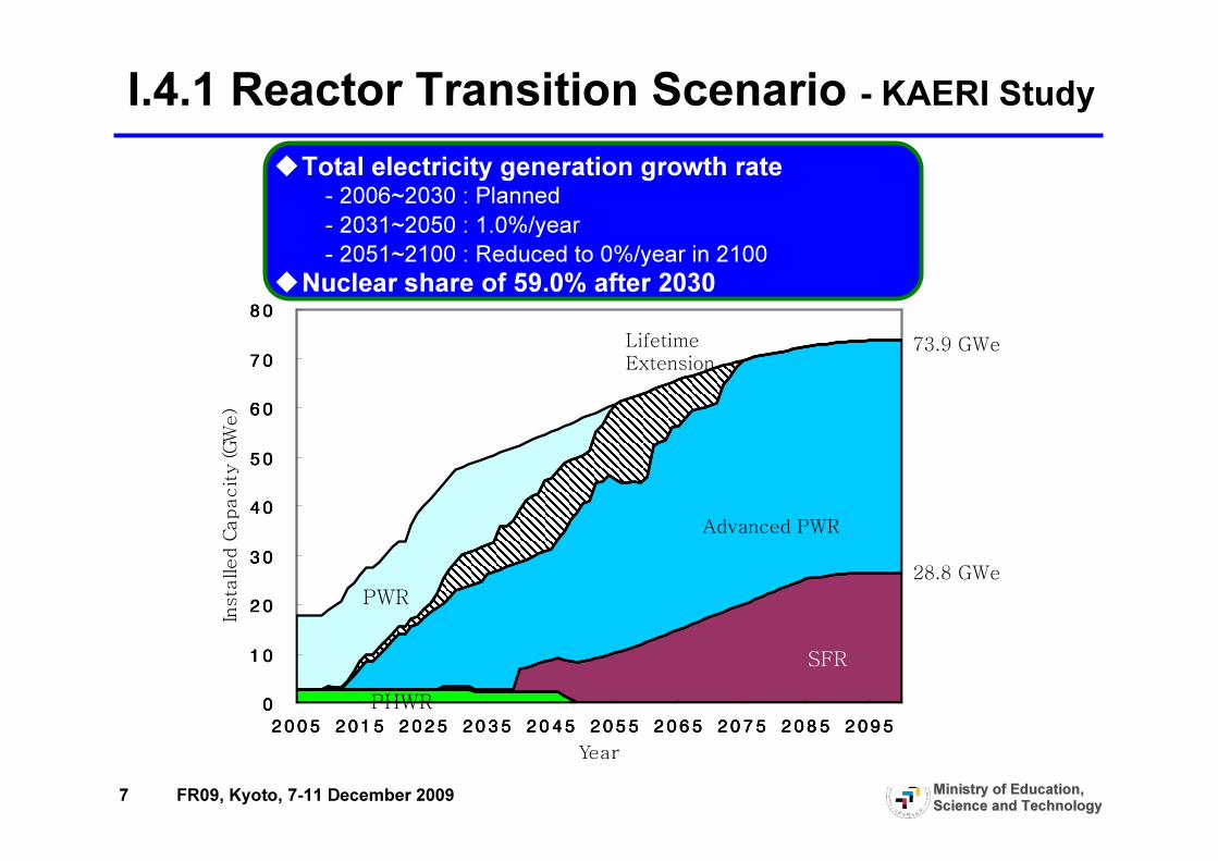
I.4.1 Reactor Transition Scenario - KAERI Study
0000
10101010
20202020
30303030
40404040
50505050
60606060
70707070
80808080
2005200520052005 2015201520152015 2025202520252025 2035203520352035 2045204520452045 2055205520552055 2065206520652065 2075207520752075 2085208520852085 2095209520952095
Year
Insta
lled C
apacity (GW
e)
Lifetime
Extension
Advanced PWR
SFR
PHWR
PWR
73.9 GWe
28.8 GWe
�Total electricity generation growth rate- 2006~2030 : Planned - 2031~2050 : 1.0%/year- 2051~2100 : Reduced to 0%/year in 2100
�Nuclear share of 59.0% after 2030
8 FR09, Kyoto, 7-11 December 2009 Ministry of Education, Ministry of Education, Science and TechnologyScience and Technology
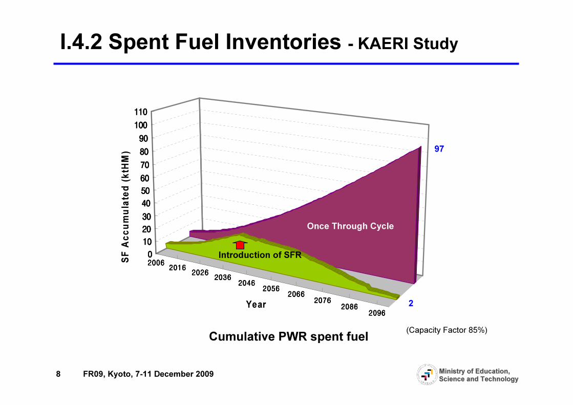
I.4.2 Spent Fuel Inventories - KAERI Study
20062006200620062016201620162016
20262026202620262036203620362036
20462046204620462056205620562056
20662066206620662076207620762076
20862086208620862096209620962096
0000
10101010
20202020
30303030
40404040
50505050
60606060
70707070
80808080
90909090
100100100100
110110110110
SF A
ccum
ulated
(ktH
M)
Year
Cumulative PWR spent fuel
Once Through Cycle
97
Introduction of SFR
2
(Capacity Factor 85%)
9 FR09, Kyoto, 7-11 December 2009 Ministry of Education, Ministry of Education, Science and TechnologyScience and Technology
SFR & Pyroprocess Development ProgramII
II.1 Long-term Development PlansII.2 Long-term Plan for SFR and PyroprocessII.3 Long-term Plan for Metal Fuel

10 FR09, Kyoto, 7-11 December 2009 Ministry of Education, Ministry of Education, Science and TechnologyScience and Technology
II.1 Long-term Development Plans� The Korea Atomic Energy Commission approved Long-term
Development Plans for Future Reactor Systems on December 22, 2008– Include Plans for SFR, Pyroprocess and VHTR– Intend to provide a consistent direction to long-term R&D activities
� Detailed Implementation Plan is now being developed–Schedule, deliverables, responsibilities and resources
� Long-term Plans are implemented through Nuclear R&D Programs of the NRF with funds from the MEST
11 FR09, Kyoto, 7-11 December 2009 Ministry of Education, Ministry of Education, Science and TechnologyScience and Technology
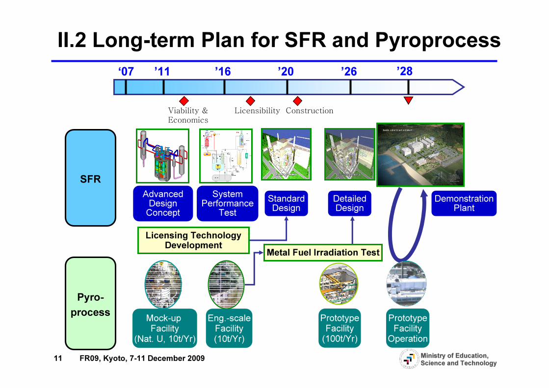
SFRSystem
Performance Test
Standard Design
Detailed Design
Demonstration Plant
Mock-up Facility
(Nat. U, 10t/Yr)Eng.-scaleFacility(10t/Yr)
PrototypeFacility(100t/Yr)
PrototypeFacilityOperation
Pyro-process
Advanced Design Concept
‘07 ’11 ’16 ’20 ’28’26
Licensing Technology Development Metal Fuel Irradiation Test
II.2 Long-term Plan for SFR and Pyroprocess
Viability &
Economics
Licensibility Construction
12 FR09, Kyoto, 7-11 December 2009 Ministry of Education, Ministry of Education, Science and TechnologyScience and Technology
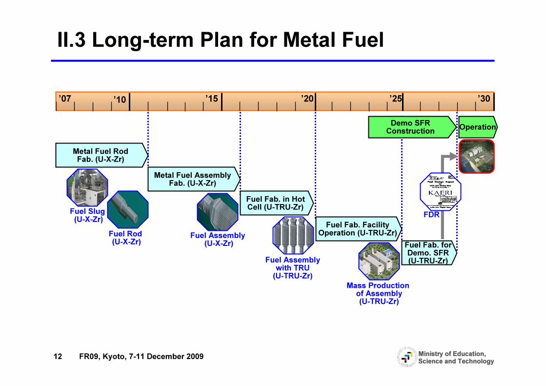
II.3 Long-term Plan for Metal Fuel
Operation
’07 ’10 ’15 ’20 ’25 ’30
Demo SFRConstruction
Metal Fuel Rod Fab. (U-X-Zr)
Metal Fuel AssemblyFab. (U-X-Zr)
Fuel Fab. in Hot Cell (U-TRU-Zr)
Fuel Fab. Facility Operation (U-TRU-Zr)
Fuel Fab. for Demo. SFR (U-TRU-Zr)
Fuel Slug (U-X-Zr)
Fuel Rod (U-X-Zr) Fuel Assembly
(U-X-Zr)Fuel Assembly with TRU (U-TRU-Zr)
Mass Production of Assembly(U-TRU-Zr)
FDR

13 FR09, Kyoto, 7-11 December 2009 Ministry of Education, Ministry of Education, Science and TechnologyScience and Technology
SFR Technology DevelopmentIII
III.1 Advanced Concept Design StudiesIII.2 R&D Activities for Advanced SFR

14 FR09, Kyoto, 7-11 December 2009 Ministry of Education, Ministry of Education, Science and TechnologyScience and Technology
III.1 Advanced Concept Design Studies
� 1200MWe, Pool-type Reactor� Fuel : U-TRU-Zr� Core I/O Temp : 390/545℃℃℃℃� DHR System : PDRC� 2-loop IHTS/SGS� Net Efficiency : 39.4%
Key Design FeaturesKey Design Features
Heat transport system of advanced pool type SFRConceptual NSSS Layout
15 FR09, Kyoto, 7-11 December 2009 Ministry of Education, Ministry of Education, Science and TechnologyScience and Technology
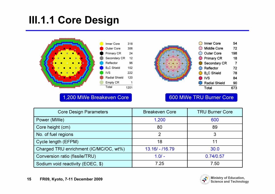
III.1.1 Core Design
Total
Inner Core 318 Outer Core 306Primary CR 24Secondary CR 12Reflector 96B4C Shield 102IVS 222Radial Shield 120Empty CR 1
1201
Inner Core 54Middle Core 72Outer Core 198Primary CR 18Secondary CR 7Reflector 72B4C Shield 78IVS 84Radial Shield 90Total 673
Inner Core 54Middle Core 72Outer Core 198Primary CR 18Secondary CR 7Reflector 72B4C Shield 78IVS 84Radial Shield 90Total 673
Core Design Parameters Breakeven Core TRU Burner CorePower (MWe) 1,200 600Core height (cm) 80 89No. of fuel regions 2 3Cycle length (EFPM) 18 11Charged TRU enrichment (IC/MC/OC, wt%) 13.16/ - /16.79 30.0 Conversion ratio (fissile/TRU) 1.0/ - 0.74/0.57Sodium void reactivity (EOEC, $) 7.25 7.50
1,200 MWe Breakeven Core 600 MWe TRU Burner Core
16 FR09, Kyoto, 7-11 December 2009 Ministry of Education, Ministry of Education, Science and TechnologyScience and Technology
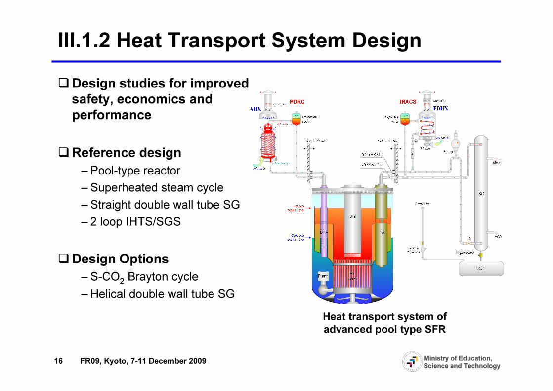
III.1.2 Heat Transport System Design
Heat transport system of advanced pool type SFR
�Design studies for improved safety, economics and performance
�Reference design– Pool-type reactor– Superheated steam cycle– Straight double wall tube SG– 2 loop IHTS/SGS
�Design Options– S-CO2 Brayton cycle– Helical double wall tube SG
17 FR09, Kyoto, 7-11 December 2009 Ministry of Education, Ministry of Education, Science and TechnologyScience and Technology
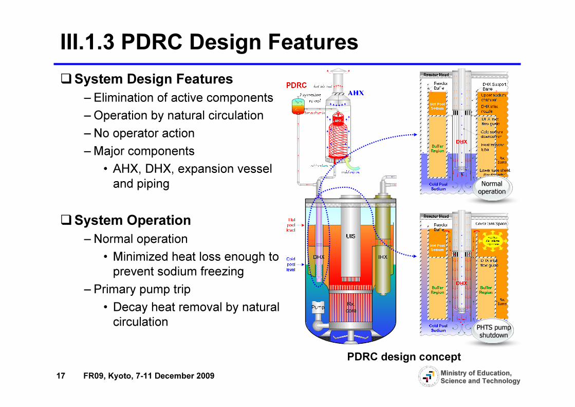
III.1.3 PDRC Design Features�System Design Features
– Elimination of active components– Operation by natural circulation– No operator action– Major components
• AHX, DHX, expansion vessel and piping
�System Operation– Normal operation
• Minimized heat loss enough to prevent sodium freezing
– Primary pump trip• Decay heat removal by natural circulation
PDRC design concept
Normal Normal operationoperation
PHTS pump PHTS pump shutdownshutdown

18 FR09, Kyoto, 7-11 December 2009 Ministry of Education, Ministry of Education, Science and TechnologyScience and Technology
III.1.4 Mechanical Structure System�Studies for a cost competitive
large scale SFR– Size optimization – Large size components arrangement
�Design Issues– Feasibility of 2 loop layouts with large size equipments
– Simplified IHTS piping with large piping diameters and SG/pump arrangements
– Integrated components�Structural design evaluation to check design feasibility
Conceptual NSSS Design
Reactor VesselReactor VesselReactor VesselReactor Vessel
- SS316
- OD 14.5m
- Length 19.0m
- Thickness 0.05m
Rx Internals Rx Internals Rx Internals Rx Internals
36 CRDMs2 RP
UISIVTM

19 FR09, Kyoto, 7-11 December 2009 Ministry of Education, Ministry of Education, Science and TechnologyScience and Technology
•PDRC experiment
Advanced Concept Design Studies
Advanced Concept Design Studies
Development of Basic Technologies
Development of Basic Technologies
Development of Advanced Technologies
Development of Advanced Technologies
•Sustainable and proliferation resistant core
•Na-CO2 interaction test
1971.57 [MW t] 16147.52 kg /s
394.27.60
Na 185.31 a tm 19.98545.0 189.2
19.98 202.77.53
RHRS
183.7364.4
9.2[MW t]
329.66 [MWt] 19.98
389.63044.5[MW t]
31.25 84.81 91.177.40 20.00 7.46
390.0
333.90 [MWt]
15445.9 kg/s71.0%29.0%
13.5 MWPump
TURBINEEff.=93.4% HTR
Ef.=91.7%
CORE
REAC TORVES SEL
COMP. #1E ff.=89.1%
COMP. #2Eff.=87.5%
COOLERCycle E ff. = 42.8 %Plan t Eff.(Gross) =41.2 %Plan t Eff.(Net) = 40.3 %
CO2
IHT S pump
Na-CO 2 HX
353.819.94
508.019.74
1528.7 [MW t] X 2
1751.31 [MWt]
4.3 X 2 MW
7400.2 kg /s X 2Na
1256.22 [MWe]
[C][MPa]
LT REf.=94.6%
0.1094526.0
0.1014364.0
0.16230.0
0.10145.0
26140.8 kg /s
1971.57 [MW t] 16147.52 kg /s
394.27.60
Na 185.31 a tm 19.98545.0 189.2
19.98 202.77.53
RHRS
183.7364.4
9.2[MW t]
329.66 [MWt] 19.98
389.63044.5[MW t]
31.25 84.81 91.177.40 20.00 7.46
390.0
333.90 [MWt]
15445.9 kg/s71.0%29.0%
13.5 MWPump
TURBINEEff.=93.4% HTR
Ef.=91.7%
CORE
REAC TORVES SEL
COMP. #1E ff.=89.1%
COMP. #2Eff.=87.5%
COOLERCycle E ff. = 42.8 %Plan t Eff.(Gross) =41.2 %Plan t Eff.(Net) = 40.3 %
CO2CO2
IHT S pump
Na-CO 2 HX
353.819.94
508.019.7419.74
1528.7 [MW t] X 2
1751.31 [MWt]
4.3 X 2 MW
7400.2 kg /s X 2Na
1256.22 [MWe]
[C][MPa][C][MPa]
LT REf.=94.6%
0.1094526.00.1094526.0
0.1014364.00.1014364.0
0.16230.00.16230.0
0.10145.00.10145.0
26140.8 kg /s
•S-CO2 Brayton cycle system
•Economic improvement of fluid and structural system
•System analysis code development •Sodium technology
development•Metal fuel technologies
Helium Gas VolumeHelium Gas VolumeHelium Gas VolumeHelium Gas Volume
245
225
CORECORECORECORE
190,195,2 00
205,210,2 15220
180
11 5
1 30
1 35
185
110
12 5
MP
120
1 40
Hot PoolHot PoolHot PoolHot Pool
23 0
235
Upper Hot PoolUpper Hot PoolUpper Hot PoolUpper Hot Pool
240
100
145
160
165
155
M P
150
170
110
IHX
280
260
285
IHX
270
250
275
735
835
73 0
83 0
740
840
1 00
0. 0
8. 2
9 .35
1 1.855
3.655
0. 128
0. 29
0.5134
0.5591
0.5075
0.55
0.5034
0.5266
0.4950
0.4950
1
35
34
33
.
.
.
5
4
3
2
36
37
38
1
35
34
33
.
.
.
5
4
3
2
36
Steam OutSteam OutSteam OutSteam Out
Water inWater inWater inWater in
IHTSIHTSIHTSIHTS
PumpPumpPumpPump
700
800
490
690
792
892
79 0
89 0 74 5
84 5
750
850
7 55
8 55
760
860
Surg e
Tank
765
865
772
872
TMDPVOL
9 10
9 50
77 587 5
920960
915
955
9 25
9 65
9 30
9 70
9 35
9 75
TMDPVOL
778
878
780
880
782
882785
885
795
895
0.6
1.19
1 10 100 1000 10000200
300
400
500
600
700
Over flow steady
Over flow start
Coastdown end
Reactor Trip(Outle t T: 555 oC)
LOHS initiation
Temp
eratur
e, o C
Time, s
Core inlet Core outlet
1 10 100 1000 100000.01
0.1
1
10
100
1000
10000
Hot Driver
B4C, IVS
ReflectorsControl Rods
Outer driversInner drivers
Middle drivers
Total
Flow
rate,
kg/s
Time, s
Helium Gas Volume245
225
CORE190,195,200205,210,215
220
180
115130
135185
110
125MP
120
140
Hot Pool230
235Upper Hot Pool
240
100
145160
165
155MP
150
170
110
IHX
280260
285
IHX
270250
275
735835
730830
740840
100
0.0
8.2
9.35
11.855
3.655
0.128
0.290.5134
0.5591
0.5075
0.55
0.50340.5266
0.4950
0.4950
1
353433...5432
363738
1
353433...5432
36
Steam Out
Water in
IHTSPump
700800
490690
792892
790890 745
845
750850
755855
760860
SurgeTank
765865
772872
TMDPVOL910950
775875
920960
915955
925965
930970
935975
TMDPVOL
778878780880782882785
885
795895
0.6
1.19
1 10 100 1000 10000200
300
400
500
600
700
Over flow steady
Over flow start
Coastdown end
Reactor Trip(Outle t T: 555 oC)
LOHS initiation
Temp
eratur
e, o C
Time, s
Core inlet Core outlet
1 10 100 1000 100000.01
0.1
1
10
100
1000
10000
Hot Driver
B4C, IVS
ReflectorsControl Rods
Outer driversInner drivers
Middle drivers
Total
Flow
rate,
kg/s
Time, s
AfterBefore
III.2 R&D Activities for Advanced SFR
•Under-sodium viewing technique
Liquid Liquid Liquid Liquid
WedgeWedgeWedgeWedge
UltrasonicUltrasonicUltrasonicUltrasonic
TransducerTransducerTransducerTransducer
AcousticAcousticAcousticAcoustic
ShieldingShieldingShieldingShielding
TubeTubeTubeTube
10 m10 m10 m10 m
WaveguideWaveguideWaveguideWaveguide
PlatePlatePlatePlate

20 FR09, Kyoto, 7-11 December 2009 Ministry of Education, Ministry of Education, Science and TechnologyScience and Technology
Pyroprocess Technology DevelopmentIV
IV.1 Pyro-Processing TechnologyIV.2 Pyro-System Engineering Technology
21 FR09, Kyoto, 7-11 December 2009 Ministry of Education, Ministry of Education, Science and TechnologyScience and Technology
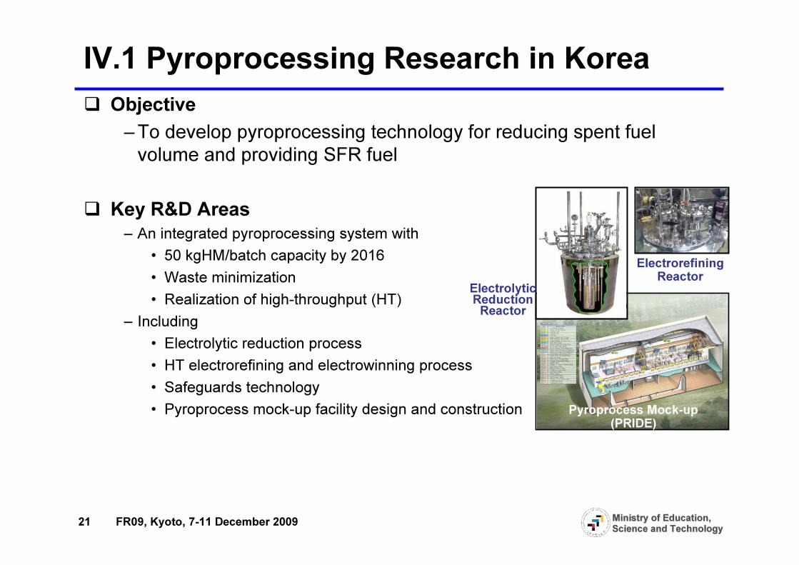
IV.1 Pyroprocessing Research in Korea� Objective
– To develop pyroprocessing technology for reducing spent fuel volume and providing SFR fuel
� Key R&D Areas– An integrated pyroprocessing system with
• 50 kgHM/batch capacity by 2016• Waste minimization• Realization of high-throughput (HT)
– Including• Electrolytic reduction process• HT electrorefining and electrowinning process• Safeguards technology• Pyroprocess mock-up facility design and construction
ElectrolyticReduction Reactor
Electrorefining Reactor
Pyroprocess Mock-up (PRIDE)
22 FR09, Kyoto, 7-11 December 2009 Ministry of Education, Ministry of Education, Science and TechnologyScience and Technology
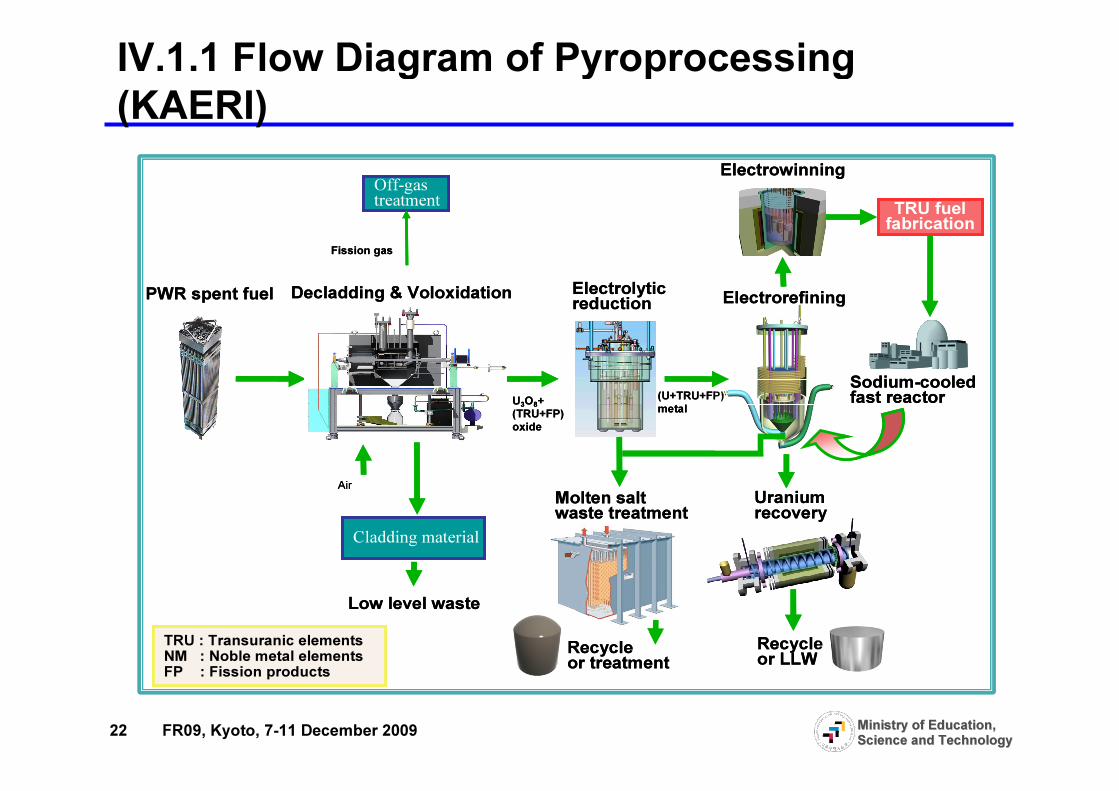
IV.1.1 Flow Diagram of Pyroprocessing (KAERI)
TRU fuelfabrication
Decladding & Voloxidation Electrolyticreduction Electrorefining
Electrowinning
Molten saltwaste treatment Uraniumrecovery
Recycleor LLWRecycleor treatment
Cladding material
Low level waste
Off-gastreatment
Sodium-cooledfast reactor
Fission gas
Air
U3O8+(TRU+FP)oxide
(U+TRU+FP)metal
PWR spent fuel
TRU : Transuranic elementsNM : Noble metal elementsFP : Fission products

23 FR09, Kyoto, 7-11 December 2009 Ministry of Education, Ministry of Education, Science and TechnologyScience and Technology
IV.1.2 R&D Issues of Pyroprocessing� Purposes
� Increase throughput� Simple and easy operation mode� Reduce waste volume
� Improvement � Graphite cathode employment to recover U in electrorefining system� Crystallization method applied to recover pure salt from waste mixture
Spent Fuel Voloxidation Electroreduction Electrorefinning Electrowining Fuel Fabrication SFRHMHMHMHM

24 FR09, Kyoto, 7-11 December 2009 Ministry of Education, Ministry of Education, Science and TechnologyScience and Technology
IV.2.1 System Engineering Technologies
25 FR09, Kyoto, 7-11 December 2009 Ministry of Education, Ministry of Education, Science and TechnologyScience and Technology
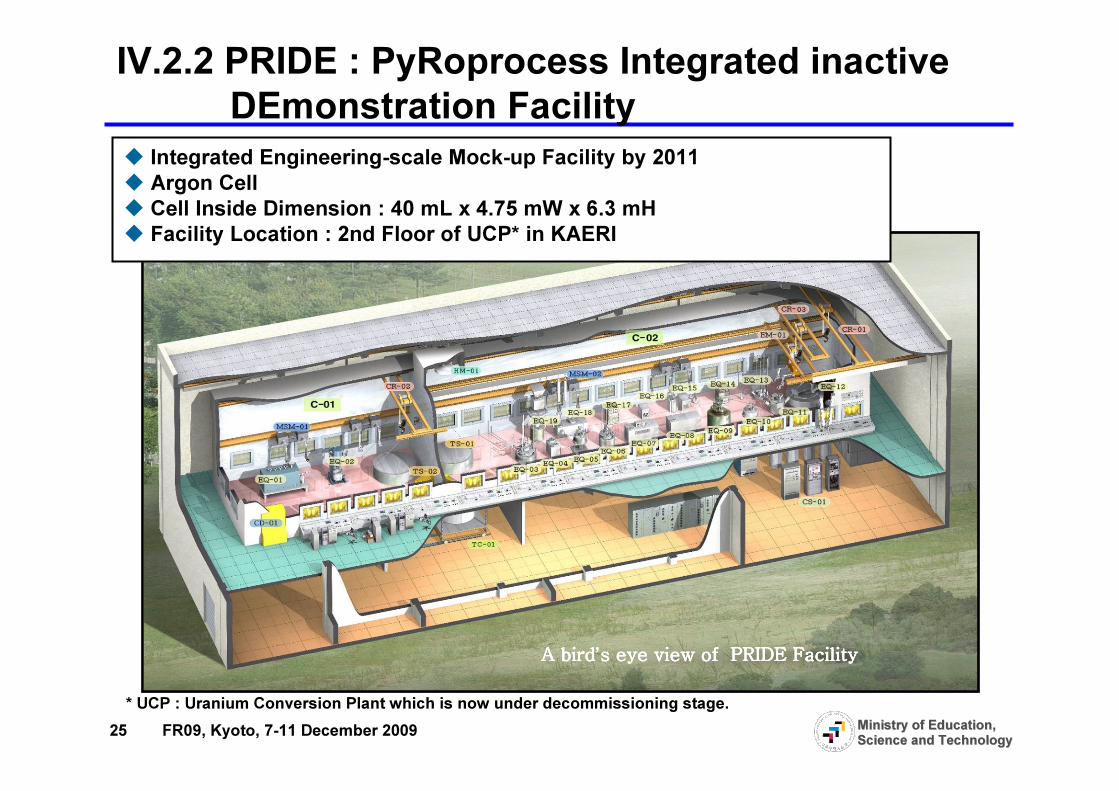
� Integrated Engineering-scale Mock-up Facility by 2011� Argon Cell� Cell Inside Dimension : 40 mL x 4.75 mW x 6.3 mH� Facility Location : 2nd Floor of UCP* in KAERI
A birdA birdA birdA bird’s eye view of PRIDE Facilitys eye view of PRIDE Facilitys eye view of PRIDE Facilitys eye view of PRIDE Facility
* UCP : Uranium Conversion Plant which is now under decommissioning stage.
IV.2.2 PRIDE : PyRoprocess Integrated inactive DEmonstration Facility

26 FR09, Kyoto, 7-11 December 2009 Ministry of Education, Ministry of Education, Science and TechnologyScience and Technology
IV.2.3 Safeguards Technology Development & International collaboration
Safeguards Technology for ACPF�Enhancement of PR of ACP�Development, Implementation, and Support of a Safeguards System for ACPF�Regional Collaboration for Transparency �Study for Neutron, Gamma, LIBS, SINRD
�Enhancement of PR of ACP�Development, Implementation, and Support of a Safeguards System for ACPF�Regional Collaboration for Transparency �Study for Neutron, Gamma, LIBS, SINRD
ROK-US PCG Collaboration for SG Tech.
NMA Technology for Pyro.
Safeguards Design and Safeguardability Assessment
IngotStorage
U-metal
ElectrolyticReduction
KMP-C
Salt Waste
KMP-FKMP-D
KMP-1NU
Argon Cell2nd Floor
Weig
ht
Voltage/Current
Imag
e
Image
Integrated S/Gs system
UCl3 Preparation
Electro-Refining
1st Floor
Waste Salt Treatment
U melting
VoloxidizerKMP-B
Weight/Radiation
KMP-G
Electro-Winning
U-metal/Waste
Waste
WasteStorage
Ingot/wastestorage
KMP-H
KMP-3
KMP-2
Waste
I ngotKMP-A
KMP-E
PRIDE Establishment of the Safeguards
System in the PRIDE
ACPF (Lab-Scale Electrolytic Reduction)
Establishment of the SafeguardsSystem in the ACPF
�NDA System Test at INL�Safeguards Study for the KAPF � Safeguardability � Proliferation Resistance Analysis
�NDA System Test at INL�Safeguards Study for the KAPF � Safeguardability � Proliferation Resistance Analysis
ROK-US under the KAERI-10 Program
�Development of Safeguards Approach for Pyroprocessing Plant�Facility Design and Plant Operation Features that facilitate the implementation of IAEA Safeguards
�Development of Safeguards Approach for Pyroprocessing Plant�Facility Design and Plant Operation Features that facilitate the implementation of IAEA Safeguards
ROK-IAEA Collaboration with MSSP
ACPF : Advanced spent fuel Conditioning Process FacilityNMA : Nuclear Material Accounting, SG : SafeguardsPRIDE : PyRoprocess Integrated inactive Demonstration facilityESPF : Engineering Scale Pyroprocessing Facility
PR: Proliferation ResidenceLIBS : Laser Induced Breakdown SpectroscopySINRD : Self Indication Neutron Resonance Densitometer
Establishment of the Safeguards System
in the ESPF
Establishment of Establishment of the Safeguards System the Safeguards System
in the ESPFin the ESPF
27 FR09, Kyoto, 7-11 December 2009 Ministry of Education, Ministry of Education, Science and TechnologyScience and Technology
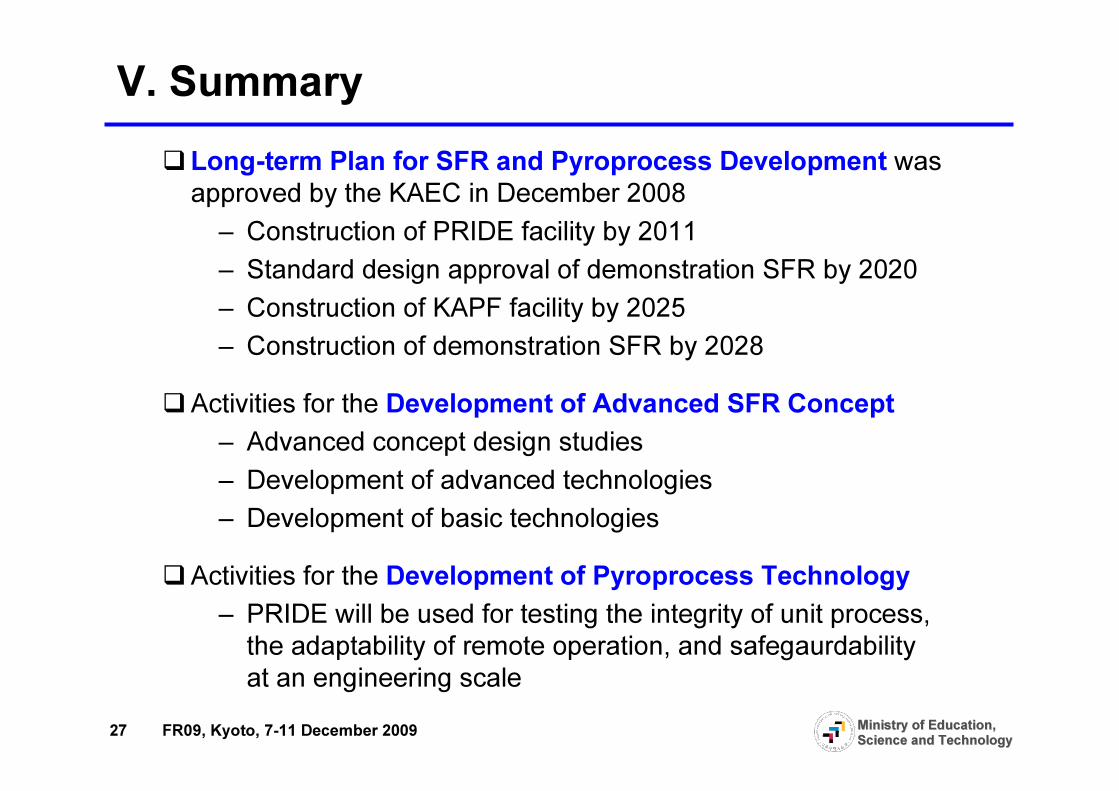
V. Summary�Long-term Plan for SFR and Pyroprocess Development was
approved by the KAEC in December 2008– Construction of PRIDE facility by 2011– Standard design approval of demonstration SFR by 2020– Construction of KAPF facility by 2025– Construction of demonstration SFR by 2028
�Activities for the Development of Advanced SFR Concept– Advanced concept design studies– Development of advanced technologies– Development of basic technologies
�Activities for the Development of Pyroprocess Technology– PRIDE will be used for testing the integrity of unit process,
the adaptability of remote operation, and safegaurdability at an engineering scale