status report on the design of the clic post-collision line
TRANSCRIPT

. . . . . .
Incoming and outgoing beam distributionsA CLIC beam in the ILC extraction line?First design of a CLIC post-collision lineStress constraints at the dump window
.
.
. ..
.
.
Status report on the design of the CLICpost-collision line
Arnaud Ferrari
Department of Nuclear and Particle PhysicsUppsala University, Sweden
CLIC meeting, CERN, 16 June 2006
Arnaud Ferrari Status report on the design of the CLIC post-collision line
. . . . . .
Incoming and outgoing beam distributionsA CLIC beam in the ILC extraction line?First design of a CLIC post-collision lineStress constraints at the dump window
.
.Introduction (1)
At CLIC, the incoming beams experience very strongelectromagnetic fields at the interaction point.
→ Increased angular divergence of the disrupted beam,emission of beamstrahlung photons (thus a larger energyspread) and production of e+e− coherent pairs.
All these particles must be transported to their dump withminimal losses in the extraction line.
In 2005, we studied the beam losses in the 20 mrad extractionline of a TeV collider (upgraded ILC or low-energy CLIC) andwe performed some benchmarking studies of tracking codes(DIMAD vs BDSIM).
Arnaud Ferrari Status report on the design of the CLIC post-collision line
. . . . . .
Incoming and outgoing beam distributionsA CLIC beam in the ILC extraction line?First design of a CLIC post-collision lineStress constraints at the dump window
.
.Introduction (2)
In 2006, we started the design of the CLIC post-collision line,where the beam disruption, beamstrahlung photon emissionand coherent pair production are much worse than at ILC.
Study of the beam losses of a nominal CLIC beam in ascaled 20 mrad ILC post-collision line.
First design of an extraction chicane, study of theconstraints for the post-collision magnets.
Study of the stress and temperature constraints at thedump window.
Arnaud Ferrari Status report on the design of the CLIC post-collision line

. . . . . .
Incoming and outgoing beam distributionsA CLIC beam in the ILC extraction line?First design of a CLIC post-collision lineStress constraints at the dump window
CLIC incoming beamsCLIC outgoing beams, ideal collisionsCLIC outgoing beams, with a vertical position/angle offset
.
.Contents
.
. . 1 Incoming and outgoing beam distributionsCLIC incoming beamsCLIC outgoing beams, ideal collisionsCLIC outgoing beams, with a vertical position/angle offset
.
. .
2 A CLIC beam in the ILC extraction line?Beam losses with nominal settingsBeam losses with down-scaled settings
.
. .
3 First design of a CLIC post-collision lineIdentification of the constraintsDesign of the extraction magnets
.
. .
4 Stress constraints at the dump window
Arnaud Ferrari Status report on the design of the CLIC post-collision line

. . . . . .
Incoming and outgoing beam distributionsA CLIC beam in the ILC extraction line?First design of a CLIC post-collision lineStress constraints at the dump window
CLIC incoming beamsCLIC outgoing beams, ideal collisionsCLIC outgoing beams, with a vertical position/angle offset
.
.Incoming beam parameters
Parameter Symbol Value Unit
Center-of-mass energy E 3 TeVParticles per bunch Nb 2.56 109
Bunches per RF pulse n 220Bunch spacing ∆tb 0.267 nsRepetition frequency f 150 HzPrimary beam power Pb 20.4 MWHorizontal normalized emittance (βγ)εx 660 nm.radVertical normalized emittance (βγ)εy 10 nm.radHorizontal rms beam size σx 60 nmVertical rms beam size σy 0.7 nmRms bunch length σz 30.8 µmPeak luminosity L 6.5 1034 cm−2 s−1
Incoming beam parameters of the nominal CLIC machine [CLIC note 627].
Arnaud Ferrari Status report on the design of the CLIC post-collision line

. . . . . .
Incoming and outgoing beam distributionsA CLIC beam in the ILC extraction line?First design of a CLIC post-collision lineStress constraints at the dump window
CLIC incoming beamsCLIC outgoing beams, ideal collisionsCLIC outgoing beams, with a vertical position/angle offset
.
.Disrupted beam distributions
Strong beam-beam interactions lead to an emittance growthand the apparition of low-energy tails in the disrupted beam.
010002000300040005000600070008000
-200 -100 0 100 200
rms(x) = 60 nm
x (nm)
Even
ts
02000400060008000
1000012000140001600018000
-4 -2 0 2 4
rms(y) = 0.65 nm
y (nm)
Even
ts
0
2000
4000
6000
8000
10000
12000
-200 -100 0 100 200
rms(x’) = 66 µrad
x’ (µrad)
Even
ts
0
2000
4000
6000
8000
10000
12000
14000
-100 -50 0 50 100
rms(y’) = 24 µrad
y’ (µrad)
Even
ts
1
10
10 2
10 3
10 4
10 5
10 6
-1 -0.8 -0.6 -0.4 -0.2 0δp/p
Even
ts
Distributions for CLIC at 3 TeV
Arnaud Ferrari Status report on the design of the CLIC post-collision line

. . . . . .
Incoming and outgoing beam distributionsA CLIC beam in the ILC extraction line?First design of a CLIC post-collision lineStress constraints at the dump window
CLIC incoming beamsCLIC outgoing beams, ideal collisionsCLIC outgoing beams, with a vertical position/angle offset
.
.Beamstrahlung photons
At CLIC, 1.1 beamstrahlung photons are emitted per incomingelectron or positron. The average energy loss of each incomingbeam through emission of photons is δB = 16%.
02000400060008000
1000012000140001600018000
-150 -100 -50 0 50 100 150
rms(x’) = 33 µrad
x’ (µrad)
Even
ts
0
2000
4000
6000
8000
10000
12000
14000
-100 -50 0 50 100
rms(y’) = 26 µrad
y’ (µrad)
Even
ts
Arnaud Ferrari Status report on the design of the CLIC post-collision line

. . . . . .
Incoming and outgoing beam distributionsA CLIC beam in the ILC extraction line?First design of a CLIC post-collision lineStress constraints at the dump window
CLIC incoming beamsCLIC outgoing beams, ideal collisionsCLIC outgoing beams, with a vertical position/angle offset
.
.Coherent pairs
At CLIC, one expects 4.6× 10⁷ coherent pairs per bunchcrossing. The electrons and positrons of the coherent pairscarry typically about 10% of the primary beam energy.
0
10
20
30
40
50
60
-150 -100 -50 0 50 100 150x (nm)
Even
ts
020406080
100120140160180200
-10 -5 0 5 10y (nm)
Even
ts
020406080
100120140160180200
-600 -400 -200 0 200 400 600x’ (µrad)
Even
ts
020406080
100120140160180200
-400 -200 0 200 400y’ (µrad)
Even
ts
1
10
10 2
-1 -0.9 -0.8 -0.7 -0.6 -0.5 -0.4 -0.3 -0.2 -0.1 0δp/p
Even
ts
* ↔ wrong-sign charged particles
Arnaud Ferrari Status report on the design of the CLIC post-collision line

. . . . . .
Incoming and outgoing beam distributionsA CLIC beam in the ILC extraction line?First design of a CLIC post-collision lineStress constraints at the dump window
CLIC incoming beamsCLIC outgoing beams, ideal collisionsCLIC outgoing beams, with a vertical position/angle offset
.
.Outgoing beams with an offset
A vertical offset in position and/or angle (∆y or ∆y ′) affects thebeam-beam effects, and thus the outgoing beam distributions.
The effects of a vertical offset were derived from numerousGUINEA-PIG simulations. For the design of the post-collisionbeam line, the most relevant effect is an increase of the verticalangular divergences.
the largest horizontal/vertical angular divergences of thedisrupted beam are about 70/75 µrad,
the largest horizontal/vertical angular divergences of thebeamstrahlung photons are about 40/80 µrad,
one may expect up to almost 108 coherent pairs per bunchcrossing (the energy spectrum is unchanged though).
Arnaud Ferrari Status report on the design of the CLIC post-collision line

. . . . . .
Incoming and outgoing beam distributionsA CLIC beam in the ILC extraction line?First design of a CLIC post-collision lineStress constraints at the dump window
CLIC incoming beamsCLIC outgoing beams, ideal collisionsCLIC outgoing beams, with a vertical position/angle offset
.
.Disrupted beams with an offset
0102030405060708090
100110120
0 10 20 30 40 50 60 70
No angular offset∆y’ = 120 µrad∆y’ = 240 µrad∆y’ = 360 µrad∆y’ = 480 µrad∆y’ = 600 µrad
Vertical position offset ∆y (nm)
Hor
izon
tal a
ngul
ar rm
s (µr
ad)
010
20
30
4050
60
70
80
0 10 20 30 40 50 60 70Vertical position offset ∆y (nm)
Ver
tical
ang
ular
rms (
µrad
)
0102030405060708090
100110120
0 200 400 600
No position offset∆y = 12 nm∆y = 24 nm
∆y = 36 nm∆y = 48 nm∆y = 60 nm
Vertical angular offset ∆y’ (µrad)
Hor
izon
tal a
ngul
ar rm
s (µr
ad)
010
20
30
4050
60
70
80
0 200 400 600Vertical angular offset ∆y’ (µrad)
Ver
tical
ang
ular
rms (
µrad
)
Arnaud Ferrari Status report on the design of the CLIC post-collision line

. . . . . .
Incoming and outgoing beam distributionsA CLIC beam in the ILC extraction line?First design of a CLIC post-collision lineStress constraints at the dump window
CLIC incoming beamsCLIC outgoing beams, ideal collisionsCLIC outgoing beams, with a vertical position/angle offset
.
.Beamstrahlung photons with an offset
0102030405060708090
100110120
0 10 20 30 40 50 60 70
No angular offset∆y’ = 120 µrad∆y’ = 240 µrad∆y’ = 360 µrad∆y’ = 480 µrad∆y’ = 600 µrad
Vertical position offset ∆y (nm)
Hor
izon
tal a
ngul
ar rm
s (µr
ad)
0102030405060708090
0 10 20 30 40 50 60 70Vertical position offset ∆y (nm)
Ver
tical
ang
ular
rms (
µrad
)
0102030405060708090
100110120
0 200 400 600
No position offset∆y = 12 nm∆y = 24 nm∆y = 36 nm∆y = 48 nm∆y = 60 nm
Vertical angular offset ∆y’ (µrad)
Hor
izon
tal a
ngul
ar rm
s (µr
ad)
0102030405060708090
0 200 400 600Vertical angular offset ∆y’ (µrad)
Ver
tical
ang
ular
rms (
µrad
)
Arnaud Ferrari Status report on the design of the CLIC post-collision line

. . . . . .
Incoming and outgoing beam distributionsA CLIC beam in the ILC extraction line?First design of a CLIC post-collision lineStress constraints at the dump window
CLIC incoming beamsCLIC outgoing beams, ideal collisionsCLIC outgoing beams, with a vertical position/angle offset
.
.Coherent pairs with an offset
020406080
100120140160180200220240260280300
0 10 20 30 40 50 60 70
No angular offset∆y’ = 120 µrad∆y’ = 240 µrad∆y’ = 360 µrad∆y’ = 480 µrad∆y’ = 600 µrad
Vertical position offset ∆y (nm)
Rms(
x’) i
n µr
ad, w
rong
-sig
n pa
rticl
es
020406080
100120140160180200220240260280300
0 10 20 30 40 50 60 70Vertical position offset ∆y (nm)
Rms(
y’) i
n µr
ad, w
rong
-sig
n pa
rticl
es
020406080
100120140160180200
0 10 20 30 40 50 60 70Vertical position offset ∆y (nm)
Rms(
x’) i
n µr
ad, r
ight
-sig
n pa
rticl
es
020406080
100120140160180200
0 10 20 30 40 50 60 70Vertical position offset ∆y (nm)
Rms(
y’) i
n µr
ad, r
ight
-sig
n pa
rticl
es
Arnaud Ferrari Status report on the design of the CLIC post-collision line

. . . . . .
Incoming and outgoing beam distributionsA CLIC beam in the ILC extraction line?First design of a CLIC post-collision lineStress constraints at the dump window
Beam losses with nominal settingsBeam losses with down-scaled settings
.
.Contents
.
. . 1 Incoming and outgoing beam distributionsCLIC incoming beamsCLIC outgoing beams, ideal collisionsCLIC outgoing beams, with a vertical position/angle offset
.
. .
2 A CLIC beam in the ILC extraction line?Beam losses with nominal settingsBeam losses with down-scaled settings
.
. .
3 First design of a CLIC post-collision lineIdentification of the constraintsDesign of the extraction magnets
.
. .
4 Stress constraints at the dump window
Arnaud Ferrari Status report on the design of the CLIC post-collision line

. . . . . .
Incoming and outgoing beam distributionsA CLIC beam in the ILC extraction line?First design of a CLIC post-collision lineStress constraints at the dump window
Beam losses with nominal settingsBeam losses with down-scaled settings
.
.The ILC 20 mrad extraction line
The ILC 20 mrad extraction line consists of a DFDF quadruplet,followed by two vertical chicanes for energy and polarizationmeasurements and a field-free region with two collimators at200 and 300 m downstream of the interaction point.
0.0 50. 100. 150. 200. 250. 300. 350. 400.s (m)
δE/ p 0c = 0 .Table name = APER
Disrupted beta functions and dispersion.
SUN version 8.23/06 01/06/05 12.38.57
0.0
500.
1000.
1500.
2000.
2500.
3000.
β1/2(m
1/2 )
0.0
0.01
0.02
0.03
0.04
0.05
0.06
0.07
0.08
0.09
0.10
Dy(m
)
βx1 / 2 βy
1 / 2 Dy
Arnaud Ferrari Status report on the design of the CLIC post-collision line

. . . . . .
Incoming and outgoing beam distributionsA CLIC beam in the ILC extraction line?First design of a CLIC post-collision lineStress constraints at the dump window
Beam losses with nominal settingsBeam losses with down-scaled settings
.
.Estimation of the power losses
The disrupted beam distributions are tracked with DIMAD, fromthe interaction point to the dump.Using the number of lost particles in the extraction line, as wellas their energy, one calculates the total beam power loss:
Ploss[W ] = 1.602× 10⁻¹⁰ Nb n fNtracks
Nloss∑
i=1
Ei .
Nb is the number of particles per bunch,
n is the number of bunches per RF pulse,
f is the repetition frequency (in Hz),
Ntracks and Nlost are the number of tracked and lost particles,
Ei is the energy of the particle i (in GeV).
Arnaud Ferrari Status report on the design of the CLIC post-collision line

. . . . . .
Incoming and outgoing beam distributionsA CLIC beam in the ILC extraction line?First design of a CLIC post-collision lineStress constraints at the dump window
Beam losses with nominal settingsBeam losses with down-scaled settings
.
.Disrupted beam losses (1)
Most of the disrupted beam losses come from the low-energytail, which tend to be over-focused in the first quadrupoles ofthe extraction line. The 20 mrad ILC extraction line only acceptsprimary electrons/positrons with Ei/E > 40%.
-1-0.9-0.8-0.7-0.6-0.5-0.4-0.3-0.2-0.1
0
0 50 100 150 200 250 300 350
Ploss = 284.3 kWCLIC 3 TeV
Distance from IP (m)
∆E/E
0
0123456789
10
0 25 50 75 100 125 150 175 200Distance from IP (m)
Pow
er lo
ss d
ensit
y (k
W/m
)
Arnaud Ferrari Status report on the design of the CLIC post-collision line

. . . . . .
Incoming and outgoing beam distributionsA CLIC beam in the ILC extraction line?First design of a CLIC post-collision lineStress constraints at the dump window
Beam losses with nominal settingsBeam losses with down-scaled settings
.
.Disrupted beam losses (2)
Magnetic elements Total beam losses Maximal loss densitySC Quadrupoles 6.5 kW 2.6 kW/mWarm Quadrupoles 61.5 kW 7.1 kW/mEnergy Chicane Magnets 48.0 kW 4.5 kW/mPolarimetry Chicane Magnets 0.8 kW 0.4 kW/m
Total beam losses and maximal loss density in the first section of the ILC 20 mradextraction line (upstream of the collimators) for CLIC at 3 TeV.
As for the beam losses in the two round collimators, we find87.8 kW in COLL1 and 11.4 kW in COLL2.
Arnaud Ferrari Status report on the design of the CLIC post-collision line

. . . . . .
Incoming and outgoing beam distributionsA CLIC beam in the ILC extraction line?First design of a CLIC post-collision lineStress constraints at the dump window
Beam losses with nominal settingsBeam losses with down-scaled settings
.
.Power losses for the coherent pairs
About 80% of the particles coming from the coherent pairs donot reach the dump. These power losses mostly occur due tothe over-focusing of low-energy particles in the quadrupolesand do not depend on the charge.
-1
-0.9
-0.8
-0.7-0.6
-0.5
-0.4-0.3
-0.2
-0.10
0 100 200 300
Right-sign particles: Ploss = 18.4 kWWrong-sign particles: Ploss = 17.8 kW
Distance from IP (m)
∆E/E
0 (%
)
0
0.2
0.4
0.60.8
1
1.21.4
1.6
1.82
0 50 100 150 200
CLIC 3 TeV, coherent pairs
Distance from IP (m)
Tota
l pow
er lo
ss d
ensit
y (k
W/m
)
Arnaud Ferrari Status report on the design of the CLIC post-collision line

. . . . . .
Incoming and outgoing beam distributionsA CLIC beam in the ILC extraction line?First design of a CLIC post-collision lineStress constraints at the dump window
Beam losses with nominal settingsBeam losses with down-scaled settings
.
.Power losses vs magnet settings
Scaling down the magnetic fields in all dipoles and quadrupolesby fQB is equivalent to changing the central energy of the beam,thus effectively reducing the total energy spread and allowingtransmission of more particles.
10-1
1
10
10 2
10 3
0 0.1 0.2 0.3 0.4 0.5 0.6 0.7 0.8 0.9 1
Disrupted beamCoherent pairs: right/wrong sign particles
Magnet scaling factor fQB
Tota
l pow
er lo
ss (k
W)
Arnaud Ferrari Status report on the design of the CLIC post-collision line

. . . . . .
Incoming and outgoing beam distributionsA CLIC beam in the ILC extraction line?First design of a CLIC post-collision lineStress constraints at the dump window
Beam losses with nominal settingsBeam losses with down-scaled settings
.
.Extraction line optics with new magnet settings (1)
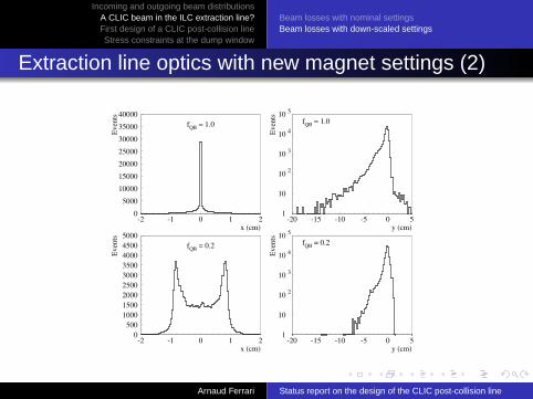
One should reduce all magnetic fields by at least a factor five toreach a reasonable level of power losses. Even so, the powerdeposited in the SC quadrupoles is still a few hundred Watts.
Also, the optics of the 20 mrad extraction line at the nominalenergy is destroyed when changing all magnetic fields in thedipoles and quadrupoles.
The optics condition for a secondary focus point is no longerfulfilled at the nominal energy.
Arnaud Ferrari Status report on the design of the CLIC post-collision line
. . . . . .
Incoming and outgoing beam distributionsA CLIC beam in the ILC extraction line?First design of a CLIC post-collision lineStress constraints at the dump window
Beam losses with nominal settingsBeam losses with down-scaled settings
.
.Extraction line optics with new magnet settings (2)
05000
10000150002000025000300003500040000
-2 -1 0 1 2
fQB = 1.0
x (cm)
Even
ts
1
10
10 2
10 3
10 4
10 5
-20 -15 -10 -5 0 5
fQB = 1.0
y (cm)
Even
ts
0500
100015002000250030003500400045005000
-2 -1 0 1 2
fQB = 0.2
x (cm)
Even
ts
1
10
10 2
10 3
10 4
10 5
-20 -15 -10 -5 0 5
fQB = 0.2
y (cm)
Even
ts
Arnaud Ferrari Status report on the design of the CLIC post-collision line

. . . . . .
Incoming and outgoing beam distributionsA CLIC beam in the ILC extraction line?First design of a CLIC post-collision lineStress constraints at the dump window
Beam losses with nominal settingsBeam losses with down-scaled settings
.
.Conclusions
A detailed study of the beam losses along the ILC 20 mradextraction line was performed, with nominal CLIC beams.
The power losses are mostly due to the low-energy tails ofthe disrupted beams and the coherent pairs, over-focusedin the first quadrupoles of the post-collision line.
The ILC 20 mrad extraction line is thus not adapted to thenominal CLIC beam, due to large losses (280 kW for thedisrupted beam and 36 kW for coherent pairs).
A strong reduction of all dipolar and quadrupolar fieldsallows to bring the power losses down to a reasonablelevel. On the other hand, the optics of the post-collisionline is destroyed at the nominal energy.
Arnaud Ferrari Status report on the design of the CLIC post-collision line

. . . . . .
Incoming and outgoing beam distributionsA CLIC beam in the ILC extraction line?First design of a CLIC post-collision lineStress constraints at the dump window
Identification of the constraintsDesign of the extraction magnets
.
.Contents
.
. . 1 Incoming and outgoing beam distributionsCLIC incoming beamsCLIC outgoing beams, ideal collisionsCLIC outgoing beams, with a vertical position/angle offset
.
. .
2 A CLIC beam in the ILC extraction line?Beam losses with nominal settingsBeam losses with down-scaled settings
.
. .
3 First design of a CLIC post-collision lineIdentification of the constraintsDesign of the extraction magnets
.
. .
4 Stress constraints at the dump window
Arnaud Ferrari Status report on the design of the CLIC post-collision line

. . . . . .
Incoming and outgoing beam distributionsA CLIC beam in the ILC extraction line?First design of a CLIC post-collision lineStress constraints at the dump window
Identification of the constraintsDesign of the extraction magnets
.
.Conceptual design
The proposed design of the CLIC post-collision line is based onthe separation by dipole magnets of the disrupted beam, thebeamstrahlung photons and the particles of the coherent pairsthat have the wrong-sign charge as compared to the outgoingbeam, just downstream of the interaction point.
Positrons from coherent pairs
Beamstrahlung photons
disrupted beam and coherent pairs)(1.5 TeV peak + long tail from the Electrons
Interaction Point
IPL
It should then be followed by a transport to the dump throughdedicated extraction lines.
Arnaud Ferrari Status report on the design of the CLIC post-collision line

. . . . . .
Incoming and outgoing beam distributionsA CLIC beam in the ILC extraction line?First design of a CLIC post-collision lineStress constraints at the dump window
Identification of the constraintsDesign of the extraction magnets
.
.Some constraints on the magnet design
We use window-frame magnets for the CLIC post-collision line:
IRON YOKE
COILS
h
d
g
BEAM
(nI)B
Ampere’s law:
nI =
∮H · ds ' B
µ0g
For the magnetic flux to returnthrough the yoke:
d ≥ Φ/2`Bmax
=⇒ d ≥ h × B2Bmax
.
Arnaud Ferrari Status report on the design of the CLIC post-collision line

. . . . . .
Incoming and outgoing beam distributionsA CLIC beam in the ILC extraction line?First design of a CLIC post-collision lineStress constraints at the dump window
Identification of the constraintsDesign of the extraction magnets
.
.Some constraints for e/γ vertical separation
For particles with a momentum p0 of 1.5 TeV/c, we want thatthe vertical deviation δy0 is 5 times larger than the worse rmsphoton cone size at the exit of the dipole [rmsγ(y’) = 80 µrad,with offset].
θ [mrad] = 0.8×(
1 +LIP
LD
)and θ [mrad] = 0.2× BLD [T.m]
BL2D − 4LD − 4LIP = 0 =⇒ LD =
2B
(1 +
√1 + LIPB
).
The field strength B should typically be of the order of 1 T. Wechoose LIP = 24 m to ensure that the post-collision extractionmagnet is outside the detector. One thus gets LD =12 m, for avertical bending angle of 2.4 mrad at 1.5 TeV.
Arnaud Ferrari Status report on the design of the CLIC post-collision line

. . . . . .
Incoming and outgoing beam distributionsA CLIC beam in the ILC extraction line?First design of a CLIC post-collision lineStress constraints at the dump window
Identification of the constraintsDesign of the extraction magnets
.
.Estimation of the pipe and magnet dimensions (1)
The conceptual design that we propose here is based on threepost-collision magnets, with a length of 4 m and spaced by 1 m.
The horizontal beam size increases linearly with the distance tothe interaction point. The most stringent constraint for the gapcomes from the coherent pairs: rms(x ′) reaches 0.15 mrad.
Xpipe(z) [cm] ≥ 0.15× z [m].
Magnet nI (A) Xcoil (cm) Ycoil (cm)
1 4.14× 10⁴ 5.2 16.02 4.77× 10⁴ 6.0 16.03 5.41× 10⁴ 6.8 16.0
Obtained with a current density of 10 A/mm2, assuming that half of the coil crosssection is used for cooling.
Arnaud Ferrari Status report on the design of the CLIC post-collision line

. . . . . .
Incoming and outgoing beam distributionsA CLIC beam in the ILC extraction line?First design of a CLIC post-collision lineStress constraints at the dump window
Identification of the constraintsDesign of the extraction magnets
.
.Estimation of the pipe and magnet dimensions (2)
In the vertical direction, one must perform particle trackings toestimate the beam size in the magnets.
In the first post-collision magnet, one must reduce the beamlosses as much as possible (direct line-of-sight to the detectorfor the secondary particles). Meanwhile, one needs a compactmagnet (close incoming beam line).
00.10.20.30.40.50.60.70.80.9
1
6 8 10 12 14 16 18 20 22
Disrupted beamCoherent pairs
Ypipe (cm)
Los
ses (
kW)
1819202122232425262728
6 8 10 12 14 16 18 20 22Ypipe (cm)
Min
imal
hor
izon
tal s
ize
(cm
)
Arnaud Ferrari Status report on the design of the CLIC post-collision line
. . . . . .
Incoming and outgoing beam distributionsA CLIC beam in the ILC extraction line?First design of a CLIC post-collision lineStress constraints at the dump window
Identification of the constraintsDesign of the extraction magnets
.
.Estimation of the pipe and magnet dimensions (3)
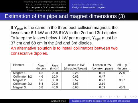
If Ypipe is the same in the three post-collision magnets, thelosses are 6.1 kW and 35.6 kW in the 2nd and 3rd dipoles.To keep the losses below 1 kW per magnet, Ypipe must be37 cm and 68 cm in the 2nd and 3rd dipoles.An alternative solution is to install collimators between twoconsecutive dipoles.
Element Xpipe Ypipe Losses in kW Losses in kW 2d + g(in cm) (in cm) (disrupted beam) (coherent pairs) (in cm)
Magnet 1 4.2 20.0 0.25 0.06 27.0Collimator 1/2 4.6 10.0 0.62 0.47 -Magnet 2 5.0 30.0 0.57 0.27 33.7Collimator 2/3 5.4 20.0 3.98 2.19 -Magnet 3 5.8 40.0 0.68 0.09 40.3
Arnaud Ferrari Status report on the design of the CLIC post-collision line

. . . . . .
Incoming and outgoing beam distributionsA CLIC beam in the ILC extraction line?First design of a CLIC post-collision lineStress constraints at the dump window
Identification of the constraintsDesign of the extraction magnets
.
.Beam profiles downstream the extraction magnets
Most of the particles that are found at the exit of the thirdpost-collision magnet carry more than 10% of the nominalbeam energy.
-25-20-15-10-505
10152025
-4 -3 -2 -1 0 1 2 3 4x(cm)
y(cm
)
1
10
10 2
10 3
10 4
10 5
-20 -10 0 10 20y(cm)
Nev
ents
0
5000
10000
15000
20000
25000
30000
35000
40000
-2 -1 0 1 2 3 4y(cm)
Nev
ents
Arnaud Ferrari Status report on the design of the CLIC post-collision line

. . . . . .
Incoming and outgoing beam distributionsA CLIC beam in the ILC extraction line?First design of a CLIC post-collision lineStress constraints at the dump window
Identification of the constraintsDesign of the extraction magnets
.
.Future investigations
The particles of the coherent pairs with the wrong-signcharge should be extracted and transported to a separatedump. This beam can be useful for diagnostics purposes.
The beamstrahlung photons and the charged particles(disrupted beam + half of the coherent pairs) can be eithertransported and analysed separately, or brought togetherto a common dump (see next slides).
Do we need soft focusing to reduce the vertical beam sizewithout extra collimators?
How do we measure the beam properties downstream theextraction magnets? Do we want a secondary focus point?
Arnaud Ferrari Status report on the design of the CLIC post-collision line

. . . . . .
Incoming and outgoing beam distributionsA CLIC beam in the ILC extraction line?First design of a CLIC post-collision lineStress constraints at the dump window
.
.Contents
.
. . 1 Incoming and outgoing beam distributionsCLIC incoming beamsCLIC outgoing beams, ideal collisionsCLIC outgoing beams, with a vertical position/angle offset
.
. .
2 A CLIC beam in the ILC extraction line?Beam losses with nominal settingsBeam losses with down-scaled settings
.
. .
3 First design of a CLIC post-collision lineIdentification of the constraintsDesign of the extraction magnets
.
. .
4 Stress constraints at the dump window
Arnaud Ferrari Status report on the design of the CLIC post-collision line

. . . . . .
Incoming and outgoing beam distributionsA CLIC beam in the ILC extraction line?First design of a CLIC post-collision lineStress constraints at the dump window
.
.A post-collision chicane for CLIC
Beam Dump
IP
verticalchicane
Photons
Primary beam
coherent pairs
The vertical chicane consists of the 3 extractionmagnets studied previously, followed by a bendin the opposite direction (also with 3 magnets).The dump is located about 100 m downstreamof the chicane. No extra focusing is used.
-1
-0.98
-0.96
-0.94
-0.92
-0.9
-0.88
-0.86
-0.84
-0.82
-0.8
0 5 10 15 20 25 30 35 40 45 50 55
Total Ploss = 35.6 kW
Disrupted beam → 23.9 kW
Coherent pairs, right-sign charge → 4.2 kW
Coherent pairs, wrong-sign charge → 7.5 kW
Distance from IP (m)
∆E/E
0
Arnaud Ferrari Status report on the design of the CLIC post-collision line

. . . . . .
Incoming and outgoing beam distributionsA CLIC beam in the ILC extraction line?First design of a CLIC post-collision lineStress constraints at the dump window
.
.Stress at the dump window
1
10
10 2
10 3
10 4
10 5
-20 -10 0 10 20y(cm)
Nev
ents
0100020003000400050006000700080009000
10000
-6 -4 -2 0 2y(cm)
Nev
ents
Beam profiles at the dump window
The stress on the window is:σ = 0.49∆pR2/d2.
We use ∆p = 1 bar, R = 10 cm andd = 3 mm → σ = 55 MPa, well belowthe stress limit of 200 MPa for copper.
Only ionization losses will occur in the window, with amagnitude (dE/dx)/ρ = 2.35 MeV/cm2g.
Arnaud Ferrari Status report on the design of the CLIC post-collision line

. . . . . .
Incoming and outgoing beam distributionsA CLIC beam in the ILC extraction line?First design of a CLIC post-collision lineStress constraints at the dump window
.
.Instantaneous temperature rise at the dump window
The instantaneous temperature rise due to the impact of a trainof (undisrupted) bunches with Ntrain = 220× 2.56 109 particlesgenerates a temperature rise T̂ :
T̂ =1ρ
(dEdx
)Ntraine
2πσxσyCv= 10.5 K
The cyclic stress due to the temperature increase is modest:
σc = αET̂/2 = 9.5 MPa
E = 110 GPa is Young’s modulus and α = 16.5× 10⁻⁶/K is thethermal expansion coefficient.
Arnaud Ferrari Status report on the design of the CLIC post-collision line

. . . . . .
Incoming and outgoing beam distributionsA CLIC beam in the ILC extraction line?First design of a CLIC post-collision lineStress constraints at the dump window
.
.Temperature evolution at the dump window
At a rate of 150 Hz, bunch trains heatthe window at the center, from wherethe heat diffuses to the edge (fixedtemperature of 37 C).
We solved the corresponding heatconduction equation with a periodicexcitation:
∂T∂t
=Dr
∂
∂rr∂T∂r
+∑
n
T̂ δ(t − n∆t),
where the thermal diffusion constantis D = 1.1 cm2/s for copper.
0 1 2 3 4 5 6 7time [s]
30
40
50
60
70
80
90
cent
er te
mpe
ratu
re [C
]
0 0.02 0.04 0.06 0.08 0.1r [m]
30
40
50
60
70
80
90
tem
pera
ture
[C]
Arnaud Ferrari Status report on the design of the CLIC post-collision line

. . . . . .
Incoming and outgoing beam distributionsA CLIC beam in the ILC extraction line?First design of a CLIC post-collision lineStress constraints at the dump window
.
.Interferometric thermometer at the dump
Use two windows spaced by 2 mm and fill the thin regionbetween them with a laminar flowing sheet of water.
If the water flows horizontally, monitor its vertical temperaturedistribution, e.g. with an interferometric thermometer. This willprovide a signal related to the vertical energy deposition andinformation on the angular divergence at the interaction point.
See V. Ziemann, Ideas for an Interferometric Thermometer,accepted for publication in Nucl. Inst. and Meth. A, 2006.
Arnaud Ferrari Status report on the design of the CLIC post-collision line

. . . . . .
Incoming and outgoing beam distributionsA CLIC beam in the ILC extraction line?First design of a CLIC post-collision lineStress constraints at the dump window
.
.Conclusion and outlooks
We presented a design of three extraction magnets toseparate the various components of the outgoing CLICbeam. Collimators are used to limit the power losses in themagnet and thereby to allow a reasonable magnet size.
As a possible extension, we presented a design of avertical chicane and studied the stress and temperaturerise at the dump window.
More studies are planned: complete separation of e/γ, useof soft focusing to reduce the beam sizes, transport of thewrong-sign charged particles, etc.
Study the impact of the beam losses on the magnet andcollimator design, as well as the effect of back-scatteredparticles on the detector background.
Arnaud Ferrari Status report on the design of the CLIC post-collision line