steady-state modeling of extrusion cast film process, neck
TRANSCRIPT

1
STEADY-STATE MODELING OF EXTRUSION CAST FILM
PROCESS, NECK-IN PHENOMENON AND RELATED
EXPERIMENTAL RESEARCH: A REVIEW
Tomas Barborik, Martin Zatloukal*
Polymer Centre, Faculty of Technology, Tomas Bata University in Zlin,
Vavreckova 275, 760 01 Zlin, Czech Republic
Keywords: Modeling of polymer processing, polymers, rheology and fluid dynamics,
polymer flows, flat film production, neck-in phenomenon.
*Corresponding author: [email protected]
Th
is is
the au
thor’s
peer
revie
wed,
acce
pted m
anus
cript.
How
ever
, the o
nline
versi
on of
reco
rd w
ill be
diffe
rent
from
this v
ersio
n onc
e it h
as be
en co
pyed
ited a
nd ty
pese
t. PL
EASE
CIT
E TH
IS A
RTIC
LE A
S DO
I: 10.1
063/5
.0004
589

2
ABSTRACT
This review paper provides the current state of knowledge of steady-state modeling of the
extrusion cast film process used to produce flat polymer films, as well as related experimental
research with a particular focus on the flow instability neck-in. All kinematic models used (i.e.
1, 1.5, 2 and 3-dimensional models) together with the utilized constitutive equations, boundary
conditions, simplified assumptions and numerical methods are carefully summarized. The
effect of draw ratio, Deborah number (i.e. melt relaxation time related to experimental time),
film cooling, second to first normal stress difference ratio at the die exit, uniaxial extensional
strain hardening and planar-to-uniaxial extensional viscosity ratio on the neck-in is discussed.
Th
is is
the au
thor’s
peer
revie
wed,
acce
pted m
anus
cript.
How
ever
, the o
nline
versi
on of
reco
rd w
ill be
diffe
rent
from
this v
ersio
n onc
e it h
as be
en co
pyed
ited a
nd ty
pese
t. PL
EASE
CIT
E TH
IS A
RTIC
LE A
S DO
I: 10.1
063/5
.0004
589

3
1 INTRODUCTION
Extrusion film casting is an industrially important process, which in practice has a solid
place among polymer processing technologies. It can be classified as a continuous, high-speed
manufacturing process, during which monolayer or co-extruded multilayer thin, highly oriented
films are produced. A wide range of the plastic films and sheets produced by this technology
are used in many different applications of daily and technical use: plastic bags, consumer
packaging, magnetic tapes for storing audio video content, optical membranes for liquid crystal
displays, flexible electronics, foils for capacitors and microporous membranes used primarily
in separation processes (from microfiltration to reverse osmosis or as separators in lithium-ion
batteries for mobile devices and electric vehicles [1–4]) or as a product for further processing
by other technologies such as thermoforming and biaxial orientation [5, 6].
The growing demand for the quantity production and quality of manufactured films,
together with the introduction of new materials, requires new approaches in production line. Of
particular interest is to reach desirable properties of the produced films and to keep film
thickness uniform and width as close as possible to the designed extrusion die width. In order
to eliminate an expensive and time-consuming trial-and-error approach widely used in the
plastics industry to optimize film casting process, one can use a computer modeling for the
optimization of die design and process conditions for a given polymer system. This strategy can
provide a better insight into the problem, broaden the knowledge on relationships between
process/rheological variables and propose possible approaches to deal with them to optimize
the process or provide a better understanding of basic underlying mechanics [6].
Th
is is
the au
thor’s
peer
revie
wed,
acce
pted m
anus
cript.
How
ever
, the o
nline
versi
on of
reco
rd w
ill be
diffe
rent
from
this v
ersio
n onc
e it h
as be
en co
pyed
ited a
nd ty
pese
t. PL
EASE
CIT
E TH
IS A
RTIC
LE A
S DO
I: 10.1
063/5
.0004
589

4
1.1 Film casting process description
The extrusion film casting is a technology, in which polymer pellets are conveyed,
homogenized, compressed and melted in an extruder. Then, the polymer melt is pushed through
the uniform slit die (center-fed T die or coat-hanger die) with typically about 1–2 mm gap size
[5]. The thick sheet is then intensively stretched in the machine direction using a constant rotary
whose circumferential velocity, vx(X), is higher than the average polymer melt velocity at the
die exit, vx(0). This leads to the orientation of macromolecules and reduced film thickness, and
due to a sufficiently high cooling rate, the final film dimensions are fixed. Intensity of the
stretching is given by a draw ratio, which is defined as ( ) ( )x xDR v X v 0= . Additionally, an
increase in DR, cooling rate or stretching distance can cause temperature and/or stress induced
crystallization, which can enhance final film properties. The process is visualized in Figure 1.
At the chill roll, several other technological devices can be used to provide a better contact
line between the film and the chill roll and to increase the heat transfer rate, such as an air knife
(a slit nozzle blows a jet of cooled air to film) or electrostatic pinning [5–7]. In the latter device,
a high voltage wire is positioned parallel to the grounded chill roll that generates an electrostatic
discharge exerting electrostatic force on the film to increase the film-chill roll contact. Another
alternative with the similar result is a vacuum box, which provides a vacuum between the film
and the chill roll [7–9]. In addition to cooling on the chill roll, the polymer film is naturally
cooled to some extent, depending on the length of the drawing zone, by passing through the
surrounding environment. This can be enhanced by introducing convection air or an inert gas
source into this section or by passing the film through a fluid bath [10]. Additionally, the
produced polymeric film can also be subjected to treatment (plasma treating, heating and biaxial
orientation) depending on the desired properties and purpose of the final product. Polymer
behavior and extensional conditions in the drawing zone have been shown to be key factors
determining the final mechanical and optical properties of the film [6, 11].
Th
is is
the au
thor’s
peer
revie
wed,
acce
pted m
anus
cript.
How
ever
, the o
nline
versi
on of
reco
rd w
ill be
diffe
rent
from
this v
ersio
n onc
e it h
as be
en co
pyed
ited a
nd ty
pese
t. PL
EASE
CIT
E TH
IS A
RTIC
LE A
S DO
I: 10.1
063/5
.0004
589

5
To produce highly functional films with tailored properties, multiple layers of different
polymer melts can be coextruded and stretched, i.e., the properties of the film are given by each
individual layer. In this way, multilayer films with enhanced properties, such as oxygen and
moisture impermeability, strength, chemical resistance or color can be produced [12]. An
alternative continuous film production technology is called the extrusion film blowing process.
In this process, the extruded tube is inflated by the internal pressure into a bubble shape having
a thin wall thickness, which is simultaneously quenched and hauled off [13–17]. In contrast to
this competing film production technology, films made by extrusion film casting have good
transparency, uniformity of thickness, a smoother surface and are produced at a higher
production rate [6].
According to the current industry practice, where a wide variety of films are produced with
a requirement for use in heterogeneous applications, manufactures process a broad range of
materials by using film casting technology. Frequently used polymeric materials include
low-density polyethylene, LDPE; high-density polyethylene, HDPE; linear low-density
polyethylene, LLDPE; polypropylene, PP; polyethylene terephthalate, PET; and polystyrene,
PS. The extrusion film casting is also suitable for low viscosity polymers [18] and
biodegradable polymers such as for example polylactide (PLA) or its blends with polybutylene
succinate (PBS) or poly(3-hydroxybutyrate-co-3-hydroxyvalerate) (PBAT) [19, 20]. Since
these films have a wide range of applications, there is a requirement to produce a wide range of
sizes. The film width can typically range from 0.1 m to 10 m, thicknesses from 20 μm to
2000 μm [11] at production rates ranging from 70 to 200 m/min. Tolerable thickness variation
is reported to be from 3 to 5 % [5]. The plastics industry, which focuses on the production of
plastic foils, is currently undergoing a major change, due to the gradual transition from
conventional commodity polymers to more advanced [6]. These include, for example,
metallocene polymers with an easily modifiable structure which make it possible to
Th
is is
the au
thor’s
peer
revie
wed,
acce
pted m
anus
cript.
How
ever
, the o
nline
versi
on of
reco
rd w
ill be
diffe
rent
from
this v
ersio
n onc
e it h
as be
en co
pyed
ited a
nd ty
pese
t. PL
EASE
CIT
E TH
IS A
RTIC
LE A
S DO
I: 10.1
063/5
.0004
589

6
significantly improve the final properties of the film. Structural polymers such as polyethylene
terephthalate, polycarbonate, polyamide, polyphenylsulfide have become popular materials for
producing films with high heat resistance. The line speed for the production of polymer films
is gradually increasing for economic reasons and in some cases (e.g. polypropylene or
polyethylene terephthalate) may reach up to 500 m/min [6].
Th
is is
the au
thor’s
peer
revie
wed,
acce
pted m
anus
cript.
How
ever
, the o
nline
versi
on of
reco
rd w
ill be
diffe
rent
from
this v
ersio
n onc
e it h
as be
en co
pyed
ited a
nd ty
pese
t. PL
EASE
CIT
E TH
IS A
RTIC
LE A
S DO
I: 10.1
063/5
.0004
589
7
2 FLOW INSTABILITIES
The presence of an air-polymer interface in the drawing zone makes it possible to develop
various types of flow instabilities that severely limit the desired film quality and quantity. Their
formation is influenced by processing conditions, heat transfer and rheology of the processed
polymer. For example, if the draw ratio reaches some critical value (for the given process
conditions, die design and polymer used), transient hydrodynamic instability, called draw
resonance, begins to occur [21]. This instability causes oscillations of the film dimensions,
although the volumetric flow supplied from the slit die and take-up speed are kept constant, see
Figure 2. These periodic fluctuations in film width and thickness (measured in the center of the
film) are offset by half-wavelength (i.e. maximum in width corresponds to the minimum
thickness) and vice versa [22]. Extension of the drawing distance, increased cooling effects and
the use of polymers with strong extensional strain hardening can stabilize the process and move
the onset of draw resonance toward higher draw ratios [23].
Film breakage is another feature that can be observed during increasing the draw ratio. In
this case, the chains cannot be reorganized to relieve local stresses within the time frame
imposed by the deformation, resulting in a cohesive failure between the polymer chains and
disintegration of the film. This can be seen in polymers containing long chain branches or a
high molecular weight portion processed at high line speeds and cooling rates, leading to good
process stability but also to the development of high tensile stress [6].
Neck-in and edge-beading are flow phenomena which are the most common instabilities in
the production of flat films because they occur and destabilize the flow at any processing
conditions. These instabilities are described and reviewed below in greater detail.
Th
is is
the au
thor’s
peer
revie
wed,
acce
pted m
anus
cript.
How
ever
, the o
nline
versi
on of
reco
rd w
ill be
diffe
rent
from
this v
ersio
n onc
e it h
as be
en co
pyed
ited a
nd ty
pese
t. PL
EASE
CIT
E TH
IS A
RTIC
LE A
S DO
I: 10.1
063/5
.0004
589

8
2.1 Neck-in
Upon leaving the die, the extruded polymer in the form of a thick sheet exhibits swelling
due to its viscoelastic nature. This relaxation of molecular stress is then influenced by the
velocity rearrangement that occurs during the transition from a confined shear flow in the slit
die to the downstream extension. When the polymer sheet is hauled off further downstream and
stable processing conditions are met, its cross-sectional dimensions are monotonically reduced
due to the external drawing force exerted on the sheet by the rotary winding drum. In addition
to the desirable reduction in film thickness, the width of the film is reduced. This defect is called
the neck-in and can be defined as the difference between the half-width of the film at the die
exit and the final half-width of the solidified film (Figure 3). The neck-in is considered to be a
typical instability occurring in extensional flows as explained by Larson in [24], even if it occurs
under steady state extrusion conditions (i.e. that the stress and the velocity are not time
dependent at the given point of the stretched film) because it can have serious consequences
since it might lead to breakage of the film.
The role of extrudate swell on the film drawing was investigated by using viscoelastic
constitutive equations such as the Leonov model [25] and the linear PTT model [26]. It was
demonstrated that the negative value of the second normal stress difference causes swelling in
the thickness direction much higher than in the width direction of the extrudate [26]. Even if
the intensity of the extrudate swell rapidly decreases by increased take-up velocity, there might
be “a certain amount of swelling persisting near the die exit” lowering the melt velocity at this
region [26]. This can increase the melt orientation because the actual DR “expressed in terms
of the velocity at the point of the film’s maximum thickness” is higher than the conventional
DR based on the melt velocity at the die exit [26].
Based on experimental studies (Table 1) and theoretical analyses (Tables 2–5), the
following material parameters and process variables have been identified to have a significant
Th
is is
the au
thor’s
peer
revie
wed,
acce
pted m
anus
cript.
How
ever
, the o
nline
versi
on of
reco
rd w
ill be
diffe
rent
from
this v
ersio
n onc
e it h
as be
en co
pyed
ited a
nd ty
pese
t. PL
EASE
CIT
E TH
IS A
RTIC
LE A
S DO
I: 10.1
063/5
.0004
589

9
impact on the neck-in phenomenon: molecular weight (Mw), molecular weight distribution
(MWD), relaxation time (), the ratio of the second and first normal stress difference at the die
exit (−N2/N1), long chain branching (LCB), strain hardening in uniaxial extension (SH in E,U),
planar to uniaxial extensional viscosity ratio (E,P/E,U), draw ratio, DR, take-up length, X, take-
up rate, vx(X), melt speed at the die exit, vx(0), and temperature T. The role of each individual
parameter on this phenomenon is summarized in Table 6. In order to clarify the reading of Table
6, let us provide here an example explaining its first line, which should be read as follows: In
1986, Dobroth and Erwin reported that the neck-in for LDPE increases if the draw ratio, DR,
(adjusted via the average polymer melt velocity at the die exit, vx(X)) increases or if the take-
up length, X, increases.
As can be seen, the reduction of the neck-in can be achieved by an increasing the polymer
melt relaxation time (via broadening MWD and/or increasing Mw and/or decreasing T),
increasing the melt speed at the die exit vx(0) (maintaining a constant DR) or reducing the
air-gap (distance between die and roll), X. All these three variables determine the elasticity of
the melt, which can be evaluated in terms of the Deborah number defined as
( )xv 0
DeX
= (1)
It is obvious, that if the Deborah number (i.e. melt elasticity) increases, the neck-in decreases
(although the stability of the process in terms of the maximum attainable draw ratio, DR, at
which the film breaks may be lowered [27–29]). Thus, it is appropriate to maintain the level of
elasticity reasonably high to minimize neck-in, which can be achieved by increasing the
relaxation time and/or the melt speed at the die exit or by reducing the air-gap (see Eq. 1). The
effect of relaxation time on the neck-in phenomenon determined experimentally for two linear
low-density polyethylenes, LLDPEs [30], and two linear polypropylenes, PPs [31–34], is
provided in Figures 4–5. It is important to mention that a different definition of relaxation time
Th
is is
the au
thor’s
peer
revie
wed,
acce
pted m
anus
cript.
How
ever
, the o
nline
versi
on of
reco
rd w
ill be
diffe
rent
from
this v
ersio
n onc
e it h
as be
en co
pyed
ited a
nd ty
pese
t. PL
EASE
CIT
E TH
IS A
RTIC
LE A
S DO
I: 10.1
063/5
.0004
589

10
can be found in the reviewed literature. In the studies based on single-mode constitutive
equations, the utilized Maxwell relaxation time [27], the shortest [35] or characteristic
relaxation time (determined by the reciprocal frequency at the intersection of the storage
modulus G’ and the loss modulus G’’ curves [36] or by fitting the strain rate dependent steady
uniaxial extensional viscosity data [37, 38]) are typically used to calculate De. In the case of
multi-mode constitutive equations, the relaxation time for each mode [39–44] or an average
relaxation time, , is calculated to determine De by using the following expression [45–47]:
N2
j j
j 1
N
j j
i 1
G
G
=
=
=
(2)
where j and Gj is the relaxation time and the modulus, respectively, in the jth relaxation mode.
Also, in some experimental studies, the longest relaxation time ( 0
0 EJ = , where 0 is the zero-
shear viscosity and 0
EJ is the linear steady-state elastic compliance) [33] or the characteristic
(reptation-mode) relaxation time representing the onset of shear-thinning [30], are used.
The role of DR on the neck-in is complex, depending whether the polymeric chains are
linear or branched or if DR is changed via vx(X) or vx(0). Current experimental studies showed
that for linear polymers (i.e. for PP, PET, LLDPE, HDPE), an increase in DR (by an increase
in vx(X)) always increases the neck-in but for branched polymers (such as LDPEs), interestingly,
the trend can even become an opposite (see Table 6 and Figure 6). This unexpected trend was
attributed to the strain-hardening behavior of LDPE in elongational flow [48]. The situation
becomes also complex, if DR is increased by reduction in vx(0) (keeping the vx(X) constant). It
was reported for branched LDPE and linear PET that an increase in DR (by decrease in vx(0))
reduces the neck-in, but for linear isotactic polypropylene (iPP) the trend was found to be
Th
is is
the au
thor’s
peer
revie
wed,
acce
pted m
anus
cript.
How
ever
, the o
nline
versi
on of
reco
rd w
ill be
diffe
rent
from
this v
ersio
n onc
e it h
as be
en co
pyed
ited a
nd ty
pese
t. PL
EASE
CIT
E TH
IS A
RTIC
LE A
S DO
I: 10.1
063/5
.0004
589

11
surprisingly opposite for given processing conditions. This unexpected trend for iPP was
attributed to the increased crystallization rate, which caused quicker film solidification.
It was found that the introduction of strain hardening, SH, in uniaxial extensional viscosity,
E,U, by incorporating long chain branches into polymer backbone chains, reduces the neck-in
phenomenon. This trend is illustrated in Figure 7 for linear low-density polyethylene and highly
branched low-density polyethylene. Seay and Baird [30] revealed that the addition of sparse
long chain branching (LCB) to polymer chains, i.e. SH in E,U, is more significant for film width
conservation than broadening the molecular weight distribution (MWD). In addition, they have
found that increasing LCB of long and short chains reduced the neck-in at low and high draw
ratios, respectively. This effect is sometimes used to improve final width for films made from
polymers prone to the neck-in (such as HDPE, LLDPE) using coextrusion technology in which
the surface/edge portion of the film is made of a material having a long-chain branching (such
as LDPE) and a core from linear polymer [49–51].
Recent viscoelastic modeling of the extrusion film casting process, which followed the
corresponding neck-in measurements, suggests that reduction of E,P/E,U or −N2/N1 at the die
exit (if De > 0.1) can also reduce the neck-in phenomenon (see Table 6).
In order to understand the role of extensional rheology and the die exit stress state, it is
necessary to discuss the mechanism and physical background of the neck-in in more detail. Ito
et al. [52], performed an experimental study on metallocene-catalyzed linear low-density
polyethylene, mLLDPE, aimed to visualize the flow in the air-gap region during a film casting
operation. They used small aluminum particles and made streamline measurement by using the
particle tracking method. These particles were placed across the film width at the die exit (one
particle for each measurement) and their movement was monitored by a camera for different
draw ratios (DR = 4.4, 7.5 and 12.2). It has been found that streamlines at the film center are
straight regardless the drawing intensity (i.e. there is planar extensional flow) whereas the
Th
is is
the au
thor’s
peer
revie
wed,
acce
pted m
anus
cript.
How
ever
, the o
nline
versi
on of
reco
rd w
ill be
diffe
rent
from
this v
ersio
n onc
e it h
as be
en co
pyed
ited a
nd ty
pese
t. PL
EASE
CIT
E TH
IS A
RTIC
LE A
S DO
I: 10.1
063/5
.0004
589

12
streamlines at the near-edge region were found to be curved with a tapered transversal spacing
in the flow direction confirming presence of uniaxial extensional flow (see Figure 8). Moreover,
an increase in the draw ratio caused an increase in the streamlines tapering, which lead to a
more pronounced neck-in phenomenon. Therefore, if E,U increases due to SH in such a way
that E,P/E,U is decreased (i.e. if the resistance against the uniaxial extensional flow becomes
much higher than the resistance against the planar extensional flow), the polymer melt starts to
prefer the planar extensional flow at the expense of the uniaxial elongation flow and thus, the
neck-in is decreased. Similarly, the reduction in −N2/N1 at the die exit physically means an
induction of a planar prestretch inside the extrusion die (for example by using converging
instead of a parallel flow channel), which (if remembered by the melts, i.e. if De > 0.1) increases
dominance of the planar extensional flow in the post die area and therefore, the neck-in is
reduced.
In the industrial practice, it is useful to have a tool that can provide a reasonable evaluation
of the neck-in for a particular polymeric material and processing conditions prior to film
production itself, where its determination via a trial-and-error approach can be very expensive.
It is therefore not surprising that considerable efforts have been made to relate the neck-in with
the air-gap, extensional strain rate and relaxation time [53] (Eqs. 3–4), both planar and uniaxial
extensional viscosities [54] (Eq. 5), and to the strain hardening, the ratio of planar to uniaxial
extensional viscosity, the Deborah number and the die exit stress state [38] (Eq. 6). These
simple analytical models are easy to use and have the advantage to gain a correlation between
the particular model variables with the naked eye in order to identify key process and material
parameters to optimize them for neck-in reduction. In more detail, Ito et al. [53] in 2003
developed a model based on the Dobroth-Erwin model [55], which assumes a planar extensional
flow in the middle of the film and a uniaxial extensional flow at the edge. According to their
Th
is is
the au
thor’s
peer
revie
wed,
acce
pted m
anus
cript.
How
ever
, the o
nline
versi
on of
reco
rd w
ill be
diffe
rent
from
this v
ersio
n onc
e it h
as be
en co
pyed
ited a
nd ty
pese
t. PL
EASE
CIT
E TH
IS A
RTIC
LE A
S DO
I: 10.1
063/5
.0004
589
13
theory, the final film width is determined by the ratio of planar viscosities in the axial and
transverse directions with respect to the flow. Proposed relationship for the neck-in, NI,
considering that the polymer melt behaves as a Newtonian fluid, is following
1
NI X2
= (3)
where the air-gap, X, is the only variable (i.e. draw ratio, deformation rate, relaxation time or
viscosity are not included). The model was tested using experimental data for linear HDPE,
short chain branched LLDPE and long chain branched LDPE melts expressed as the neck-in
plotted against the air-gap at four different draw ratios. The model was shown to correctly
predict the general trend between NI and X, i.e. an increase in X causes an increase in NI, and
the predicted slope of the theoretical line was close to experimental data for HDPE and LLDPE
at short air-gap values and the highest draw ratios at given processing conditions. On the other
hand, the model tended to overpredict NI (especially for LDPE) without the ability to predict
the effect of draw ratio on NI, as expected due to the absence of deformation rate and any
rheological parameters in Eq. 3. If the upper convected Maxwell model is used, the expression
for NI yields the following form
( )p
1NI 1 2 X
2= − (4)
where p denotes the extensional strain rate of the planar part defined as ( )=p pd t / dt
( p is the Hencky strain of the planar deformation) and λ is the characteristic relaxation time.
Although the neck-in trend predictions are consistent with the observations with respect to the
melt elasticity or the air-gap, the model unrealistically predicts neck-in decrease for the
increased draw-down ratio, which was attributed to the used constitutive equation. Further
works have moved further and tried to predict neck-in based on uniaxial and planar extensional
viscosities. Shiromoto et al. [54] in 2010 developed a theoretical model based on the force
Th
is is
the au
thor’s
peer
revie
wed,
acce
pted m
anus
cript.
How
ever
, the o
nline
versi
on of
reco
rd w
ill be
diffe
rent
from
this v
ersio
n onc
e it h
as be
en co
pyed
ited a
nd ty
pese
t. PL
EASE
CIT
E TH
IS A
RTIC
LE A
S DO
I: 10.1
063/5
.0004
589

14
balance and film deformation in the post die area. The authors found that NI can be correlated
with the planar to uniaxial extensional viscosity ratio rather than with the strain hardening in
uniaxial extension or with the ratio of planar viscosities. These findings were transformed into
the following expression for NI
0.5
E,P
E,U
NI X
(5)
where ηE,P and ηE,U denotes planar and uniaxial extensional viscosity. Eq. 5 was validated using
relevant experimental data for three long chain branched LDPEs having different Mw and
MWD. The ratio ηE,P/ηE,U was determined for all three samples using the multi-mode
exponential type of Phan–Thien and Tanner constitutive model utilizing parameters identified
on the experimental data obtained from rotational and capillary rheometers. ηE,U at low
deformation rates and high extensional rates was determined with a Meissner-type rheometer
(ARES-EVF, TA Instruments) and the Cogswell method [56], respectively. The key limitation
of the Eq. 5 is the absence of variables allowing to evaluate the role of the Deborah number and
the die exit stress state on NI. Barborik and Zatloukal [37, 38] continued the research of the
neck-in phenomenon in the period 2017-2018 with respect to the ratio of the second and first
normal stress difference at the die exit, −N2/N1, uniaxial extensional strain hardening,
ηE,U,max/3η0, melt elasticity (captured via the Deborah number, De) and the ratio of planar-to-
uniaxial extensional viscosity, ηE,P/ηE,U. Using an isothermal 1.5-dimensional (1.5D) membrane
model and viscoelastic modified Leonov constitutive equation, the following expression for
maximum attainable neck-in was proposed:
Th
is is
the au
thor’s
peer
revie
wed,
acce
pted m
anus
cript.
How
ever
, the o
nline
versi
on of
reco
rd w
ill be
diffe
rent
from
this v
ersio
n onc
e it h
as be
en co
pyed
ited a
nd ty
pese
t. PL
EASE
CIT
E TH
IS A
RTIC
LE A
S DO
I: 10.1
063/5
.0004
589

15
( )
( )
( )
2.113
7.43
0.514
0.593 1 exp 1073.742 1
1 1.027arctan 0.849X
NI
arctan 0.514 tanh 3.953
1.027 1 exp 0.849
− − − +
+
= +
− −
E,P
E,U
2
1
E,U,maxE,U,max
00
ηDe
η
N
N
ηηDe
3η3η
De
(6)
The predictions of the model were found to be in good agreement with the corresponding
experimental data [38] (see Figure 9) capturing all the trends obtained numerically, i.e. that NI
is reduced if
• −N2/N1 at the die exit decreases (i.e. for increased planar pre-stretch of the melt inside
the extrusion die),
• De increases,
• ηE,P/ηE,U decreases,
• ηE,U,max/3η0 increases.
It has also been revealed that there is a threshold of about 0.1 for De above which the neck-in
phenomenon starts to be strongly dependent on the −N2/N1 ratio at the die exit. In other words,
if De > 0.1, the flow history inside the die (i.e. the die design) starts to significantly affect the
neck-in phenomenon. It is important to mention that Eq. 6 represents an analytical
approximation of numerical solutions based on an isothermal (1.5D) membrane model utilizing
the modified Leonov constitutive equation (single mode) for the processing conditions, in
which the maximum attainable neck-in is achieved (i.e. for very high draw ratios only) were
0.011 De 0.253 , E,P
E,U
η0.825 1.910
η ,
E,U,max
0
η2.047 10.096
3η and
2
1
N0.017 0.680
N − . The basic form of Eq. 6 has been derived from the assumed linear
Th
is is
the au
thor’s
peer
revie
wed,
acce
pted m
anus
cript.
How
ever
, the o
nline
versi
on of
reco
rd w
ill be
diffe
rent
from
this v
ersio
n onc
e it h
as be
en co
pyed
ited a
nd ty
pese
t. PL
EASE
CIT
E TH
IS A
RTIC
LE A
S DO
I: 10.1
063/5
.0004
589

16
function between NI and E,P E ,U/ , in which its constants were allowed to vary with De
according to the Avrami exponential functions. Detailed derivation of Eq. 6 is provided in [37,
38]. Validation of Eq. 6 was performed for different highly branched LDPEs. All rheological
quantities appearing in Eq. 6 were predicted by the single-mode modified Leonov model whose
parameters were identified from uniaxial extensional viscosity data only. This procedure seems
to be reasonable at least for the given LDPEs and applied processing conditions. In order to
experimentally evaluate ηE,P/ηE,U, one could use the Cogswell model and measured entrance
pressure drops on capillary rheometer by using circular and rectangle capillaries [57, 58]
whereas −N2/N1 can be evaluated using Han’s methods utilizing exit pressure drop measures
by using a capillary rheometer equipped by a slit die [59–64]. The key advantage of Eq. 6 in
contrary to Eqs. 3–5 is a consideration of uniaxial and planar extensional viscositites along with
the Deborah number and die exit stress state (quantified via −N2/N1). On the other hand, the
model is only applicable to very high draw ratios and does not take into account the full
relaxation spectrum, film cooling and crystallization, which can be considered as its key
limitations.
2.2 Edge-beading
In addition to the neck-in phenomenon, an interrelated defect, referred to as the edge-beading
or the dog-bone defect, is formed making the edge portions of the film substantially thicker
than its central part (Figure 10). The size of these raised parts can be five times higher compared
to the center and several centimeters wide. The predominant cause of the edge-beads formation
is the edge-stress effect [55] arising due to the neck-in phenomenon and it’s intensity increases
with the draw ratio (see Figure 11). The following equation was derived in [55] to evaluate the
edge-beading:
Th
is is
the au
thor’s
peer
revie
wed,
acce
pted m
anus
cript.
How
ever
, the o
nline
versi
on of
reco
rd w
ill be
diffe
rent
from
this v
ersio
n onc
e it h
as be
en co
pyed
ited a
nd ty
pese
t. PL
EASE
CIT
E TH
IS A
RTIC
LE A
S DO
I: 10.1
063/5
.0004
589

17
edge
f
center
f
hB DR
h= = (7)
where B is the bead ratio and edge
fh and center
fh represents edge and center final thickness,
respectively. This equation was derived by simply comparing the strains of the center
(undergoing planar stretch) and edge (undergoing uniaxial stretch) elements between the roll
and the die neglecting surface tension, extrudate swell and assuming melt incompressibility (i.e.
without the need to use any constitutive equation). Equation 7 was successfully validated for
LDPE for DR between 1 and 20 [55] (see Figure 12). It has also been shown (when comparing
simulations based on the Newtonian and UCM models) that increasing the melt elasticity (by
increasing the Deborah number) decreases the intensity of the edge-beading [28].
The raised edges are often trimmed with a slit razer, scrapped and optionally reprocessed
to achieve a uniform film surface. Regardless of the large amount of waste material, the
occurrence of edge-beads also causes air entrapment between the film and the chill roll, which
in turn results in poorer film quality. In the manufacturing practice, a technological procedure
of opening lateral parts of the extrusion slit die (i.e. the gap size at the edge is bigger than in the
center) can be found in order to create thicker edges that would restrain the neck-in level in
comparison to the situations when the edge-beads and the neck-in would evolved in the natural
way [11].
Th
is is
the au
thor’s
peer
revie
wed,
acce
pted m
anus
cript.
How
ever
, the o
nline
versi
on of
reco
rd w
ill be
diffe
rent
from
this v
ersio
n onc
e it h
as be
en co
pyed
ited a
nd ty
pese
t. PL
EASE
CIT
E TH
IS A
RTIC
LE A
S DO
I: 10.1
063/5
.0004
589

18
3 MATHEMATICAL MODELING OF THE EXTRUSION FILM CASTING
PROCESS
The drawing of polymer films or filaments has taken an enormous amount of attention and
has been extensively studied both experimentally and theoretically in the past four decades
because of its great importance in the polymer processing industry.
3.1 Flow kinematics
Individual research groups focused on experimental works [30, 48, 52, 55, 65–74] dealing
with flow visualization, effects of temperature, crystallization, molecular weight distribution or
long chain branching on kinetics of the film casting process (see Table 1). Theoretical research
has not disappeared, and attention has been drawn to the development and use of numerical
models (primarily considering steady-state conditions) of different dimensionality such as
1D [22, 25, 26, 45, 75–85], 1.5D [18, 27, 47, 53, 86–93, 29, 94–100, 35, 37, 38, 41–44], 2D [8,
12, 28, 36, 39, 40, 46, 54, 101–113] and full 3D [114–116] (see Tables 2–5) using different
types of constitutive equations taking into account non-isothermal effects, crystallization,
inertia, and gravity. The 1D model here is based on the assumption of an infinite film width and
assumes the following velocity field
( )x xv v x= (8)
yv 0= (9)
xz
vv z
x
= −
(10)
that is, the flow deformation in the drawing region is planar [52, 55]. The 1.5D model is simply
the 1D model with variable film width proposed in [27, 28]. This simplified model, which
Th
is is
the au
thor’s
peer
revie
wed,
acce
pted m
anus
cript.
How
ever
, the o
nline
versi
on of
reco
rd w
ill be
diffe
rent
from
this v
ersio
n onc
e it h
as be
en co
pyed
ited a
nd ty
pese
t. PL
EASE
CIT
E TH
IS A
RTIC
LE A
S DO
I: 10.1
063/5
.0004
589

19
retains the ability to cover the reduction in film width in the drawing length while reducing the
dimensionality of the solved problem, is based on the assumption that all velocity components
are an exclusive function of the drawing length position, x, and vary linearly with respect to its
corresponding direction. In this case, a velocity field is assumed in form of
( )x xv v x= (11)
( )yv yf x= (12)
( )zv zg x= − (13)
The 2D approximation developed in [112, 113] is based on the so-called membrane
hypothesis considering that one dimension of the film is small compared to the others [112].
The film thickness is much smaller (several orders of magnitude) than the film width and the
take-up length, so it can be assumed that the velocity component in the machine and the
transversal direction are independent of thickness direction, i.e., uniform across the thickness.
The reduced velocity field is given in the following form
( )x xv v x, y= (14)
( )y yv v x, y= (15)
yx
z
vvv z
x y
= − +
(16)
The 3D model utilizes velocity components without any restriction, which are given bellow:
( )x xv v x, y, z= (17)
( )y yv v x, y, z= (18)
( )z zv v x, y, z= (19)
Th
is is
the au
thor’s
peer
revie
wed,
acce
pted m
anus
cript.
How
ever
, the o
nline
versi
on of
reco
rd w
ill be
diffe
rent
from
this v
ersio
n onc
e it h
as be
en co
pyed
ited a
nd ty
pese
t. PL
EASE
CIT
E TH
IS A
RTIC
LE A
S DO
I: 10.1
063/5
.0004
589

20
3.2 Constitutive equations
Different types of constitutive equations were used to model film casting, as shown in
Tables 2–5. They are introduced and briefly discussed in this chapter. For simplicity, they are
usually provided in a single mode version. Note that in the multi-mode approach, a
discontinuous relaxation spectrum is used and the stress tensor is expressed as N
jj 1=
= where
j represents the stress tensor in the jth mode.
3.2.1 Newtonian model
This constitutive equation describes the behavior of ideal Newtonian fluids by Eq. 20.
02 D = (20)
Here is the extra stress tensor, 0 is the Newtonian shear viscosity (zero-shear-rate viscosity)
and D is the deformation rate tensor defined as
( )T
v v v
1D L L , L v
2= + = (21)
where v represents the velocity field, T denotes the transpose of the tensor and is the gradient
operator. The Newtonian model predicts constant steady shear viscosity (0), steady uniaxial
(30) and planar (40) extensional viscosities, which is correct also for polymer melts, but only
at very low extensional rates, where they behave as Newtonian fluids. The key advantage of
this model is its mathematical simplicity and utilization of only one adjustable parameter, 0,
which can be determined from simple shear flow measurements. On the other hand, the model
does not have the ability to describe the elasticity and memory of fluids, the extensional strain
thinning or the extensional strain hardening, typically occurring for polymer melts at medium
and high extensional strain rates. It has been found that the model provides reasonable NI values
Th
is is
the au
thor’s
peer
revie
wed,
acce
pted m
anus
cript.
How
ever
, the o
nline
versi
on of
reco
rd w
ill be
diffe
rent
from
this v
ersio
n onc
e it h
as be
en co
pyed
ited a
nd ty
pese
t. PL
EASE
CIT
E TH
IS A
RTIC
LE A
S DO
I: 10.1
063/5
.0004
589

21
only at low DR values, it predicts essentially parabolic thickness profile across the film width
as well as increased NI values with increased DR [105]. The convergence is almost guaranteed
[89]. At high DRs, the Newtonian model predicts artificially high neck-in, and there are also
discrepancies between experiments and temperature profile predictions, as shown for PET in
[90] (see Figure 13). This constitutive equation was used in the following studies: 1.D (4 works)
[80], [82], [22], [26]; 1.5D (10 works) [18], [100], [86], [87], [88], [27], [89], [90], [53], [97];
2D (10 works) [112], [12], [28], [101], [102], [39], [104], [105], [113], [111]; 3D (1 work)
[114].
3.2.2 Generalized Newtonian model
The generalized Newtonian model is simply the Newtonian model given by Eq. 20, in which
0 is replaced by a viscosity scalar function ( )DII , which is allowed to vary with the second
invariant of deformation rate tensor DII defined as ( )22tr D . In the simple shear flow, 2
DII =
, uniaxial extensional flow, 2
DII 3= , and planar extensional flow, 2
DII 4= . Here and
represents shear and extensional strain rate, respectively.
Power-law (or Ostwald–de Waele) model [117–119]
( ) ( )n 1
D DII m II−
= (22)
where m (the flow consistency index) and n (the flow behavior index, which is lower than 1 for
polymer melts) are adjustable parameters. This model allows to model shear, uniaxial and
planar extensional viscosities plotted as the function of deformation rates as a simple line in
log-log scale with the slope equal to n-1. The key advantage of this model its mathematical
simplicity and low number of used parameters. A key disadvantage of this model is over
Th
is is
the au
thor’s
peer
revie
wed,
acce
pted m
anus
cript.
How
ever
, the o
nline
versi
on of
reco
rd w
ill be
diffe
rent
from
this v
ersio
n onc
e it h
as be
en co
pyed
ited a
nd ty
pese
t. PL
EASE
CIT
E TH
IS A
RTIC
LE A
S DO
I: 10.1
063/5
.0004
589

22
prediction of shear and extensional viscosities at low deformation rates, the incapability to
describe a smooth transition from Newtonian to non-Newtonian flow regime and the
incapability to represent fluid elasticity, memory and extensional rheology. It was found that
model predictions start to significantly deviate from the Newtonian solution when the power-
law index n becomes less than 0.8 [113]. This model was utilized in the following studies within
this review: 1.D (1 work) [81]; 1.5D (0); 2D (2 works) [113], [8]; 3D (0).
Cross model [120]
( )( )
0D a
D
II
1 II
− = +
+
(23)
The model was used in: 1.D (0); 1.5D (3 works) [91], [93], [96]; 2D (1 work) [105]; 3D (0).
Carreau model [121]
( )
( )
0D 1 n
2 2
D
II
1 II
−
− = +
+
(24)
The model was used in: 2D (2 works) [110], [111]; 3D (1 work) [115].
Carreau-Yasuda model [122]
( )
( )
0D 1 n
a a
D
II
1 II
−
− = +
+
(25)
The model was used in: 1.D (1 work) [79]; 1.5D (0) ; 2D (1 work) [40]; 3D (0).
The above viscosity models use the following parameters: η0 (zero-shear-rate viscosity), η∞
(infinite-shear-rate viscosity), λ (relaxation time), a (characterizes the sharpness of the
transition from Newtonian to non-Newtonian flow regime) and n (characterizes the slope
between viscosity and deformation rate in a log-log scale) are model parameters. Utilization of
low number of parameters, mathematical simplicity, capability to represent steady shear
viscosity of polymer melts in a wide range of shear rates and correct predictions of steady
Th
is is
the au
thor’s
peer
revie
wed,
acce
pted m
anus
cript.
How
ever
, the o
nline
versi
on of
reco
rd w
ill be
diffe
rent
from
this v
ersio
n onc
e it h
as be
en co
pyed
ited a
nd ty
pese
t. PL
EASE
CIT
E TH
IS A
RTIC
LE A
S DO
I: 10.1
063/5
.0004
589

23
extensional viscosities at low extensional rates (i.e. equal to 30 and 40 for uniaxial and planar
extensional viscosities, respectively) represent the advantages of these models. The main
disadvantages are the inability to represent fluid memory and extensional rheology for branched
polymers.
The use of generalized Newtonian models in film casting modeling has made it possible to
capture some very important trends observed experimentally, namely that NI intensity and the
edge bead increase with DR or that an increase in planar to uniaxial extensional viscosity ratio
increases NI, in agreement with the viscoelastic PTT model [40], [110].
3.2.3 Upper-Convected Maxwell (UCM) model
One of the simplest model allowing to represent some basic viscoelastic features of polymer
melts is called the Upper-Convected Maxwell model, which is given by the Eq. 26.
02 D
+ = (26)
As can be seen, the key difference between the Newtonian and the Upper-Convected Maxwell
model is the elastic term
, which consists of the relaxation time, , and the upper-convected
time derivative of the stress tensor,
, defined as
( )T
v vv L L
t
= + − −
(27)
The key advantage of this model is its mathematical simplicity, low number of used parameters
(, 0, or alternatively and the elastic modulus G where 0 = G), it takes into account the
melt memory and the first normal stress difference, N1, is predicted to be nonzero.
Disadvantages: The model predicts unrealistically strong extensional strain hardening without
the ability to predict the extensional strain thinning and it yields an infinite steady uniaxial and
Th
is is
the au
thor’s
peer
revie
wed,
acce
pted m
anus
cript.
How
ever
, the o
nline
versi
on of
reco
rd w
ill be
diffe
rent
from
this v
ersio
n onc
e it h
as be
en co
pyed
ited a
nd ty
pese
t. PL
EASE
CIT
E TH
IS A
RTIC
LE A
S DO
I: 10.1
063/5
.0004
589

24
planar extensional viscosities at 1
2 =
, as can be deduced from Eqs. 28–29 resulting from this
model for steady uniaxial, E,U, and planar, E,P, extensional viscosities:
( )( )
0E,U
3
1 2 1
=
− + (28)
( )( )
0E,P
4
1 2 1 2
=
− + (29)
The model also unrealistically predicts a constant steady shear viscosity (equal to 0) and the
second normal stress difference, N2, equal to zero.
The use of the UCM model made it possible to reveal the qualitative role of melt
elasticity in the film casting process. It was found that the edge bead defect was more
pronounced in the Newtonian case than in the viscoelastic case (see Figure 14) and that
increasing the melt elasticity (i.e. the Deborah number) reduces NI [28], which is in good
agreement with the experimental results. This constitutive equation was utilized in the
following studies: 1.D (2 works) [85], [83]; 1.5D (8 works) [27], [89], [53], [94], [99], [29],
[98], [44]; 2D (4 works) [113], [28], [8], [106]; 3D (0).
3.2.4 Generalized Upper-Convected Maxwell model
The generalized Upper-Convected Maxwell model is simply the UCM model, in which the
relaxation time and the shear viscosity are allowed to vary with the second invariant of the
deformation rate tensor:
( ) ( )D DII 2 II D
+ = (30)
Th
is is
the au
thor’s
peer
revie
wed,
acce
pted m
anus
cript.
How
ever
, the o
nline
versi
on of
reco
rd w
ill be
diffe
rent
from
this v
ersio
n onc
e it h
as be
en co
pyed
ited a
nd ty
pese
t. PL
EASE
CIT
E TH
IS A
RTIC
LE A
S DO
I: 10.1
063/5
.0004
589

25
For the film casting modeling, the shear viscosity, ( )DII , was chosen as the Carreau function
(Eq. 24 with = 0) and the relaxation time, ( )DII , in the form of the Eq. 31.
( )
( )0
D n2
t D
II
1 II
=
+
(31)
In this equation, 0, t and n are adjustable parameters. The model can represent steady shear
viscosity, N1 and extensional rheology more realistically than the UCM model but it still shares
the key disadvantages of the original model, i.e., N2 is predicted to be zero and steady uniaxial
and planar extensional viscosities becomes infinite, if the extensional strain rate becomes equal
to ( )1
2 DII. This model was used in the film casting modeling (1.D (1 work in total) [83]) to
understand the role of the power-law exponent n and the characteristic relaxation time on the
velocity profile and the relationship between DR and tensile force.
3.2.5 Giesekus model
The Giesekus model was proposed in 1966 from the simple dumbbell theory for dilute solutions
considering anisotropic drag [119, 123–125]. The model is given as follows:
p s
= + (32)
s
2 D = (33)
2
1 1 pp p pp
2 D
+ + =
(34)
0 p = + (35)
0 1G = (36)
Th
is is
the au
thor’s
peer
revie
wed,
acce
pted m
anus
cript.
How
ever
, the o
nline
versi
on of
reco
rd w
ill be
diffe
rent
from
this v
ersio
n onc
e it h
as be
en co
pyed
ited a
nd ty
pese
t. PL
EASE
CIT
E TH
IS A
RTIC
LE A
S DO
I: 10.1
063/5
.0004
589

26
2
0
1
=
(37)
where is the extra-stress tensor, p
and s
is the polymer and the solvent contribution to the
stress tensor, is the solvent viscosity, p is the polymer viscosity, D is the deformation rate
tensor, 1 is the relaxation time, the symbol represents the upper-convected time derivative,
0 is the zero-shear-rate viscosity, G is the modulus and is the parameter characterizing
anisotropic hydrodynamic drag. The minimum and maximum anisotropies correspond to = 0
and = 1, respectively [125], but as shown by Bird [119], the model behaves realistically only
if 0.5. This model can represent a steady shear viscosity of polymer melts in very wide
shear rate range and it correctly predicts non-zero values of N1 as well as negative value of N2.
On the other hand, its behavior in an extensional flow is not realistic. The key disadvantage of
this model is the inability to predict the decrease in extensional viscosity, if the extensional
strain rate increases. The model has been found to provide reasonable predictions for the film
neck-in, the centerline velocity profile and the temperature drop in the air-gap and it also
predicts an increase in film neck-in and the temperature drop in the air-gap as the air-gap length
is increased [107].
This constitutive equation has been used in the following studies: 1.D (1 work) [79]; 1.5D (0) ;
2D (3 works) [113], [107], [111]; 3D (0).
3.2.6 Modified Giesekus model
The original Giesekus model is not able to realistically represent extensional flows because the
polymeric chains are assumed to be infinitely extensible. In order to overcome this model
drawback, Wiest [126] modified the original Giesekus model [124] by incorporating the finite
extensibility of polymer molecules by using the Peterlin approximation. The set of equations
Th
is is
the au
thor’s
peer
revie
wed,
acce
pted m
anus
cript.
How
ever
, the o
nline
versi
on of
reco
rd w
ill be
diffe
rent
from
this v
ersio
n onc
e it h
as be
en co
pyed
ited a
nd ty
pese
t. PL
EASE
CIT
E TH
IS A
RTIC
LE A
S DO
I: 10.1
063/5
.0004
589

27
remains the same as in the case of the original Giesekus model except for Eq. 34, which must
be replaced by the following expression
( ) ( )21
1 1 pp p pp
Dln Z Dln ZZ 1Z 2 D
Dt 2 Dt
− + + = +
(38)
where is the Kronecker delta and Z is the function defined as
( )p
c
c
tr1Z b 3
b G
= + +
(39)
The term D()/Dt represents substantial time derivative, which is defined as
( ) ( )
( )D
vDt t
= +
(40)
In this model bc represents the chain extensibility parameter. Note that if → cb , →Z 1 , the
modified model is reduced to the original Giesekus model whereas for = 0, the “FENE-P”
dumbbell constitutive equation is recovered [126]. This model shares the same advantages with
the original Giesekus model with the additional ability to describe extensional strain hardening
as well as extensional strain thinning for steady uniaxial as well we as planar extensional
viscosities. In addition, the model is derived from kinetic theory, which allows to relate model
parameters with molecular characteristics. On the other hand, the model predicts that both
uniaxial and planar extensional viscosities are very similar at high deformation rates [84], which
might not be realistic, as indicated in [127].
The model was used to investigate the role of the uniaxial extensional strain hardening
on velocity and stress profiles and film tension in single layer as well as the multilayer film
casting process by using 1.D flow kinematics [84], [75], [76].
Th
is is
the au
thor’s
peer
revie
wed,
acce
pted m
anus
cript.
How
ever
, the o
nline
versi
on of
reco
rd w
ill be
diffe
rent
from
this v
ersio
n onc
e it h
as be
en co
pyed
ited a
nd ty
pese
t. PL
EASE
CIT
E TH
IS A
RTIC
LE A
S DO
I: 10.1
063/5
.0004
589

28
3.2.7 eXtended Pom-Pom model
The eXtended Pom-Pom (XPP) model was proposed by Verbeeten et al. [128]. This model
represents an approximation of the original Pom–Pom model proposed by McLeish and Larson
[129], which is based on the Doi-Edwards reptation tube theory and uses the Giesekus
anisotropy parameter α. The model considers a simplified H topology of branched molecules
and the relaxation time is expressed as a tensor to separate the stretch and orientation. The
model is given by the following set of equations:
( )1
2GD
− + = (41)
where the relaxation time tensor is defined as
( ) ( ) ( )1 1 1 1
0b
1f G f 1
G
− − − − = + + − (42)
Extra function:
( )( )2
1 0b
2 2
s
tr2 1 1f 1 1
3G
− = − + −
(43)
Backbone stretch and stretch relaxation time:
( )tr
13G
= + ,
( )1
s 0se− −
= , 2
q = (44)
where q (number of arms), λ0S (stretch relaxation time) are adjustable parameters, which are
allowed to vary with the orientation relaxation time, λ0b. Note that the Maxwell parameters are
G and λ0b = λ. The model has an excellent capability to describe the shear and extensional
rheology for long-chain branched polymers such as LDPE, which is widely used in the film
casting technology. The model also predicts non-zero values of N1 and N2 as it should be.
Additionally, the model parameters are directly related to the molecular characteristics because
the model is derived from molecular arguments. On the other hand, the model is not suitable
Th
is is
the au
thor’s
peer
revie
wed,
acce
pted m
anus
cript.
How
ever
, the o
nline
versi
on of
reco
rd w
ill be
diffe
rent
from
this v
ersio
n onc
e it h
as be
en co
pyed
ited a
nd ty
pese
t. PL
EASE
CIT
E TH
IS A
RTIC
LE A
S DO
I: 10.1
063/5
.0004
589

29
for linear polymers due to the assumed structural topology and uses a very high number of
adjustable parameters, which makes it difficult to identify them from the measured
experimental data. The model (similarly to the original Pom-Pom model) also predicts that
steady uniaxial and planar extensional viscosities becomes practically identical at high
extensional strain rates, which might not be realistic for some LDPEs, as indicated in [127] (see
Figure 15). The XPP model correctly predicts that increasing DR and the air-gap reduce NI.
According to the authors, the agreement between the experimental data (LDPE [41], [42] and
long chain branched PP [43]) and the simulation results was qualitative rather than quantitative
in terms of necking behavior (see Figure 16 as the example for LDPE; here the 8 mode XPP
model, in which all model parameters were allowed to vary with the relaxation mode, was used;
step shear and step uniaxial extensional experiments were used to validate the XPP model).
This constitutive equation was utilized in the following studies: 1.D (0); 1.5D (3 works) [41],
[42], [43]; 2D (0); 3D (0).
3.2.8 Rolie–Poly Stretch (RP-S) model
Rolie–Poly (ROuse LInear Entangled POLYmer) stretch model is a tube-based model proposed
by Likhtman and Graham [130], which takes into account the convective constraint release,
reptation and chain retraction. The model is given as
( )( )
( )0
c
d r
2 1 3 tr tr1
3
−
= − − − + −
(45)
where d and
r are the reptation and the Rouse relaxation times, respectively; c is the
convective constraint release coefficient, 0 is a fitting scalar parameter. Being c equal to
zero, 0 parameter does not have to be specified. This model has showed a good capability to
describe the transient shear and extensional rheology of linear film casting resins (namely
LLDPE and HDPE), it is mathematically simple and gives a non-zero value of N1. On the other
Th
is is
the au
thor’s
peer
revie
wed,
acce
pted m
anus
cript.
How
ever
, the o
nline
versi
on of
reco
rd w
ill be
diffe
rent
from
this v
ersio
n onc
e it h
as be
en co
pyed
ited a
nd ty
pese
t. PL
EASE
CIT
E TH
IS A
RTIC
LE A
S DO
I: 10.1
063/5
.0004
589
30
hand, the model is not able to describe the rheological behavior of branched polymers and
unrealistically predicts N2 = 0 [131]. This constitutive equation was utilized in the following
theoretical studies summarized in this review: 1.D (0); 1.5D (3 works) [41], [42], [43]; 2D (0)
; 3D (0). The model predicted an increase in NI with increased DR and the air-gap. According
to the authors, the agreement between the experimental data (HDPE [41]; LLDPE [41], [42];
and linear PP [43]) and the simulation results was qualitative rather than quantitative with
respect to NI (see Figure 17 as an example for LLDPE; here the 8 mode RP-S model, in which
d and r were allowed to vary with the relaxation mode, was used; = 0 and 0 0.5 = − ; step
shear and step uniaxial extensional experiments were used to validate the RP-S model).
3.2.9 Modified Leonov model
The modified Leonov model is based on heuristic thermodynamic arguments resulting from the
theory of rubber elasticity [132–137]. In this constitutive equation, a fading memory of the melt
is determined by an irreversible dissipation process driven by the dissipation term, b . This
model relates the stress and elastic strain stored in the polymer melt as:
1
c c
W W2 c c
I II
−
= −
(46)
where W is the elastic potential, which depends on the invariants cI and cII of the recoverable
Finger tensor c ,
( )
( )L Ln 1 n 1
c c
L
I II3GW 1 1 1
2 n 1 3 3
+ + = − − + −
+
(47)
where G denotes the linear Hookean elastic modulus, and Ln are numerical parameters.
Leonov assumed that the dissipative process acts to produce an irreversible rate of strain p
e
Th
is is
the au
thor’s
peer
revie
wed,
acce
pted m
anus
cript.
How
ever
, the o
nline
versi
on of
reco
rd w
ill be
diffe
rent
from
this v
ersio
n onc
e it h
as be
en co
pyed
ited a
nd ty
pese
t. PL
EASE
CIT
E TH
IS A
RTIC
LE A
S DO
I: 10.1
063/5
.0004
589

31
c c1
p
I IIe b c b c
3 3
−
= − − −
(48)
which spontaneously reduces the rate of elastic strain accumulation. Here, δ is the unit tensor
and b stands for the dissipation function defined by Eq. 50. This elastic strain c is related to
the deformation rate tensor D as follows
p
c c D D c 2c e 0− − + =
(49)
where c is the Jaumann (corotational) time derivative of the recoverable Finger strain
tensor. The dissipation function b proposed in [64] is given as
( )( )
( )c
c c
c
sinh I 31b I exp I 3
4 I 3 1
− = − − + − +
(50)
where and are adjustable parameters of the model.
The model has a very good capability to describe shear viscosity, N1, N2, uniaxial and planar
extensional viscosities for linear as well as branched polymers [57, 58, 62–64, 138]. The model
also offers an independent control of uniaxial and planar extensional viscosities, which was
used for systematic investigation of the role of planar to uniaxial extensional viscosity ratio on
the film casting process for different LDPEs. On the other hand, the interpretation of molecular
meaning of the used model parameters is limited because the model is derived from
thermodynamics rather than molecular arguments. Note that the original Leonov model is
recovered if nL = = = = 0.
The model demonstrated the ability to describe film casting experimental data for linear (PP)
as well as branched (LDPE) polymers even by using a single mode (i.e. utilizing a single pair
of and G) only [35, 37, 38] (see Figure 18; In the case of PP, the lowest relaxation time typical
for polyolefins was chosen and G was calculated from the known 0. The nonlinear model
Th
is is
the au
thor’s
peer
revie
wed,
acce
pted m
anus
cript.
How
ever
, the o
nline
versi
on of
reco
rd w
ill be
diffe
rent
from
this v
ersio
n onc
e it h
as be
en co
pyed
ited a
nd ty
pese
t. PL
EASE
CIT
E TH
IS A
RTIC
LE A
S DO
I: 10.1
063/5
.0004
589
32
parameters were adjusted as the typical values for linear polymers, i.e. = 0, nL = 0, = 0.5,
= 0.5. In the case of LDPE, the model parameters, namely , G, , , were identified using
deformation rate dependent ‘steady state’ uniaxial extensional viscosity experimental data and
known 0. The parameter nL was kept equal to zero). The modified Leonov model was used in
the following studies: 1.D (0); 1.5D (3 works) [37], [38], [35]; 2D (0); 3D (0). The original
Leonov model was used only in: 1.5D (1 work) [25].
3.2.10 Phan-Thien-Tanner (PPT) model
The model was derived by Phan-Thien and Tanner [139] and Phan-Thien [140] from the Lodge-
Yamamoto network theory, in which junctions are allowed to form and decay due to the flow.
The model is given by the following equation
( ) 02 D
+ = (51)
This model uses the Gordon–Schowalter convected time derivative of the stress tensor,
,
defined as
( )T
vt
= + − −
,
pvL D= − (52)
and the relaxation time, ( ) , which is allowed to vary with the trace of the stress linearly
(Eq. 53) or exponentially (Eq. 54).
Linear PTT model:
( ) ( )p1 tr
G
= + (53)
Exponential PTT model:
( ) ( )pexp tr
G
=
(54)
Th
is is
the au
thor’s
peer
revie
wed,
acce
pted m
anus
cript.
How
ever
, the o
nline
versi
on of
reco
rd w
ill be
diffe
rent
from
this v
ersio
n onc
e it h
as be
en co
pyed
ited a
nd ty
pese
t. PL
EASE
CIT
E TH
IS A
RTIC
LE A
S DO
I: 10.1
063/5
.0004
589

33
The model utilizes two parameters, p and p (together with and G, where 0 = G). The linear
PTT predicts an unrealistically monotonically increasing extensional viscosity, while the
exponential PTT has the ability to give a maximum in the extensional viscosity, when plotted
as a function of the extensional strain rate. Thus, the exponential PTT model is used more in
modeling of the film casting process than its linear version; it has a good ability to describe
shear as well as extensional rheology of linear as well as branched polymers and predicts non-
zero values for N1 and N2. On the other hand, steady uniaxial and planar extensional viscosities
are predicted to be practically identical at high extensional strain rates, which might not be
realistic for some polymers, as indicated in [127] (see Figure 19). This model has been shown
to provide good agreement with experimental data for LDPE over a wide range of the take-up
velocity and the air-gap length [109], [54] (see Figure 20). In this case, the exponential (6-7)
mode PTT model using p and p model parameters varying with each relaxation mode was
necessary to adequately represent the measured shear and extensional data LDPEs reasonably.
The discrete relaxation spectrum was determined from frequency-dependent loss and storage
moduli, while p and p parameters were identified from steady state shear viscosity vs. shear
rate and steady uniaxial extensional viscosity vs. extensional strain rate.
This constitutive equation was utilized in the following studies within this review:
1.D (1 work) [79]; 1.5D (2 works) [47], [44]; 2D (7 works) [46], [105], [36], [108], [109], [54],
[40]; 3D (1 work) [116]. The linear variant of the PTT model was used only in: 2D (1 work)
[26].
Th
is is
the au
thor’s
peer
revie
wed,
acce
pted m
anus
cript.
How
ever
, the o
nline
versi
on of
reco
rd w
ill be
diffe
rent
from
this v
ersio
n onc
e it h
as be
en co
pyed
ited a
nd ty
pese
t. PL
EASE
CIT
E TH
IS A
RTIC
LE A
S DO
I: 10.1
063/5
.0004
589

34
3.2.11 Larson model
This model represents a differential approximation of the Doi-Edwards (DE) integral tube
model proposed by Larson [141, 142], which includes non-affine motion and is given by the
following expression:
( ) 0
2D : G 2 D
3 G
+ + + = (55)
where is the only non-linear model parameter (note that the best approximation of the DE
model is achieved, if 3 5 = [125]). The behavior of the model is comparable to the
exponential PTT model meaning that it can capture shear and extensional viscosities for both
linear and branched polymers, and N1 is predicted to be a non-zero value. However, the model
unrealistically predicts N2 = 0, steady uniaxial and planar extensional viscosities becomes
comparable at high extensional strain rates, and must be varied with the relaxation time to
capture uniaxial extensional strain hardening for commercial types of highly branched
polyethylenes over a wide range of extensional strain rates. This model was successfully used
in the film casting modeling for 4 different types of LDPEs, but 13 pairs of , G, were needed
to describe the experimental reality [39]. The model provides reasonably good predictions for
the neck-in and the film thickness (see Figure 21). This model also predicts that the increase in
the uniaxial extensional strain hardening firstly, decreases NI in agreement with experimental
observations (see Figure 22), and secondly, the edge beading region becomes narrower.
This constitutive equation was utilized in the following studies: 1.D (0); 1.5D (0) ; 2D (2
works) [39], [105]; 3D (0).
Th
is is
the au
thor’s
peer
revie
wed,
acce
pted m
anus
cript.
How
ever
, the o
nline
versi
on of
reco
rd w
ill be
diffe
rent
from
this v
ersio
n onc
e it h
as be
en co
pyed
ited a
nd ty
pese
t. PL
EASE
CIT
E TH
IS A
RTIC
LE A
S DO
I: 10.1
063/5
.0004
589

35
3.2.12 Integral constitutive equation of the K-BKZ type with PSM strain-memory
function
The multi-mode Kaye-Bernstein-Kearsley-Zapas (K-BKZ) type of the integral model
proposed by Papanastasiou, Scriven, Macosko (PSM) [143] and then modified by Luo and
Tanner [144] to account for N2 through the parameter has the following expression:
( )( ) ( )
1 1
Nt 1j j
j 1 j j j j jC C
G1 t texp C t C t dt
1 3 I 1 II− −
−
−=
− = − + − − + + −
(56)
where t and t are the times present and past, respectively, 1−C
I and 1−C
II are the first and
second invariant of the Finger strain tensor 1−
C ; j , j and are the parameters of the model.
The K-BKZ model reduces to the upper-convected Maxwell model when = 0 and → + .
The model has a very good ability to describe the shear viscosity, N1, N2 and uniaxial
extensional viscosities for linear and branched polymers. The main disadvantage of the model
is the inability to predict extensional strain hardening in planar extensional viscosity for
branched polymers as LDPE [145] (see Figure 23).
The model showed a good agreement between experimental data and previous film casting
simulations based on the Newtonian and UCM results in terms of film thickness, width and
temperature [89]. Note that in order to capture the shear and extensional rheology of LDPE
melts, the parameter in Eq. 56 needs to be varied with the relaxation time, otherwise the
extensional strain hardening is overpredicted at high extensional strain rates (see Figure 23).
This constitutive equation was utilized in the following studies: 1.D (1 work) [45];
1.5D (1 work) [89]; 2D (0); 3D (0).
Th
is is
the au
thor’s
peer
revie
wed,
acce
pted m
anus
cript.
How
ever
, the o
nline
versi
on of
reco
rd w
ill be
diffe
rent
from
this v
ersio
n onc
e it h
as be
en co
pyed
ited a
nd ty
pese
t. PL
EASE
CIT
E TH
IS A
RTIC
LE A
S DO
I: 10.1
063/5
.0004
589

36
3.2.13 Hooke’s Law with creep
Smith and Stolle considered the viscoelastic polymer melt to be an elastic material that is
creeping. For such a description, they have suggested the incremental form of Hooke’s law of
the following form [146]:
( )cE = − (57)
where is the stress increment, E is the elasticity matrix, is the total strain increment
and c
is the modified Perzyna creep strain increment that depends on the time step, the
effective creep strain rate and the second invariant of the deviatoric stress tensor. This model
was used to theoretically investigate the role of elasticity (by changing the relaxation time) and
extensional strain hardening. It was found that the predictions were consistent with predictions
of the conventional viscoelastic model i.e. that NI decreases with increased extensional strain
hardening and the relaxation time. Note that the model uses only one constant relaxation time
and modulus, and its ability to describe rheological experimental data has not been provided by
the authors.
This constitutive equation was utilized in the following studies: 1.D (2 works) [77], [78];
1.5D (0) ; 2D (1 work) [103]; 3D (0).
3.3 Boundary conditions for viscoelastic constitutive equations
If viscoelastic constitutive equations are used, the additional boundary stress condition at
the die exit must be specified. This boundary condition is given by both, the flow in the die
(upstream) and the extensional flow in the drawing length (downstream). Accurate
determination of this additional boundary stress value therefore requires an intensive numerical
Th
is is
the au
thor’s
peer
revie
wed,
acce
pted m
anus
cript.
How
ever
, the o
nline
versi
on of
reco
rd w
ill be
diffe
rent
from
this v
ersio
n onc
e it h
as be
en co
pyed
ited a
nd ty
pese
t. PL
EASE
CIT
E TH
IS A
RTIC
LE A
S DO
I: 10.1
063/5
.0004
589
37
computation [46]. The following paragraphs summarize the approaches used to determine these
types of boundary conditions (see also Tables 2–5).
Anturkar and Co [83] in their study, using the generalized upper-convected Maxwell model,
estimated axial component of the stress tensor, xx , as the mean stress value for a
fully-developed slit flow in an infinitely wide die. Silagy et al. [27] and [28] based on Denn et
al. [147] and Demay et al. [88, 148] assumed two different stress states at the end of the die. In
the first case, the extra stress in the machine direction, xx , equals zero, so the extra stresses are
completely released due to the die swell, or the second, which assumed the mean value of the
extra stress after flow in an infinite die with a rectangular cross section while the transversal
extra stress, yy , is set to the value obtained from the Newtonian solution. They found that the
initial stress conditions at the die exit had little effect on the final shape of the film, but
calculations were performed only for low Deborah numbers. Iyengar and Co [84] took a
different approach, and instead of specifying the axial stress component, set the ratio zz xx to
the value between two extreme cases for planar extensional flow and a fully-developed slit flow
in the die noting that the true stress ratio should have lied in their range. Iyengar [149] then
reported that both extreme cases with corresponding stress ratios provide very similar velocity
and stress profiles. Debbaut at al. [113] in their viscoelastic study assumed an initial stresses of
zero. Same as in Smith’s work [8].
For a multilayer film casting analysis (based on a single-mode modified Giesekus model)
Pis-Lopez and Co [76, 150] showed that if the aspect ratio (defined here as the ratio of the total
film thickness at the die exit to the drawing distance 2e0/X) is smaller than 0.05, the velocity
and stress profiles converge to the same values, regardless of whether the initial stress condition
is based on the assumption of a fully-developed slit flow or a fully-developed planar extensional
flow. In another study using a multi-mode model approach, Denn [151] left the longest
relaxation mode unspecified at the die exit, and rest of the modes were set with respect to this
Th
is is
the au
thor’s
peer
revie
wed,
acce
pted m
anus
cript.
How
ever
, the o
nline
versi
on of
reco
rd w
ill be
diffe
rent
from
this v
ersio
n onc
e it h
as be
en co
pyed
ited a
nd ty
pese
t. PL
EASE
CIT
E TH
IS A
RTIC
LE A
S DO
I: 10.1
063/5
.0004
589

38
mode. In contrast, Christodoulou et al. [46] concluded that the shortest mode should be left
unspecified with the reasoning that the longest mode p
xx( N ) is mainly determined by the flow
inside the die, while the shorter modes p
xx( j ) are determined by the external flow in the air gap.
Beris and Liu [152, 153] in their fiber spinning study for the single mode UCM viscoelastic
liquid specified the die exit stress state through the ratio of normal to axial stress, yy xx , and
not each component separately. This value was approximated as the value bellow the
homogeneous steady extensional flow at the effective extensional strain rate. For the
viscoelastic multimode model, Denn [151] specified also p p
xx( j ) xx( N ) for j < N as an extra
condition to p p
yy( j ) xx( j ) for all relaxation modes.
Devereux and Denn [154] proposed the same distribution between partial stresses as in the
case of a fully-developed capillary flow with neglected radial partial stresses. The remaining
initial stresses were adjusted to satisfy the downstream boundary condition (see Eq. 58).
p
xx( j) j j
Np
xx(N)j j
j 1
G
G=
=
(58)
Note that Gagon and Denn [155] simplified the above-mentioned relationship for the wedge
spectrum into
xx( j) j
xx(N) N
=
(59)
Barborik and Zatloukal [37, 38] recently defined the state of the stress at the die exit by the
ratio of the second to the first normal stress difference, −N2/N1, calculated from the upstream
side by using the viscoelastic modified Leonov constitutive equation.
( ) ( )
( ) ( )
zz yy2
1 xx zz
0 0N
N 0 0
− − = −
− (60)
Th
is is
the au
thor’s
peer
revie
wed,
acce
pted m
anus
cript.
How
ever
, the o
nline
versi
on of
reco
rd w
ill be
diffe
rent
from
this v
ersio
n onc
e it h
as be
en co
pyed
ited a
nd ty
pese
t. PL
EASE
CIT
E TH
IS A
RTIC
LE A
S DO
I: 10.1
063/5
.0004
589

39
It has been found that if the Deborah number is less than 0.1, the choice of initial stress
conditions at the die exit has little effect on the steady-state calculations. However, at higher
Deborah numbers, the die exit stress state, which may be influenced, for example, by extrusion
die design, starts to significantly affect the neck-in phenomenon.
3.4 Overview on steady-state film casting modeling
Initial efforts have been made for a fiber spinning process in which the flow kinematics are
mathematically similar when considered as a one-dimensional flow, for the Newtonian and
Maxwell fluids by Gelder [156] and Fisher [157, 158], respectively. These studies focused on
the draw resonance phenomenon, that Christensen [159] and Miller [160] first encountered, and
who postulated that the nature of this phenomenon is not of viscoelastic, as it can also be
observed in Newtonian fluids. Extending the kinematics of the process to two or three
dimensions, both processes become different and one can observe phenomena in the film
casting, which have no counterpart in the fiber spinning, i.e. neck-in and edge-beading. The
above preliminary studies provided the background for extended studies on the extrusion film
casting (EFC). Initial attempts to simulate EFC operations were devoted to investigating the
stability of the process and determining the onset of draw resonance, rather than quantifying
the extent of the neck-in phenomenon. The very first study of EFC process modeling in this
way was carried out by Yeow [80] using numerical modeling. For the steady state solution,
he used a one-dimensional isothermal model for Newtonian fluid (planar extensional free
surface flow) and investigated the effect of introduced small two-dimensional perturbances on
flow stability (namely transverse perturbations). The edge-effects, surface tension,
aerodynamic drag and fluid inertia and gravity were neglected. A small curvature of the film
was assumed along with a uniform axial stress and axial velocity over the film thickness. Due
to the assumed free surface flow kinematics in the drawing section, the model could not capture
Th
is is
the au
thor’s
peer
revie
wed,
acce
pted m
anus
cript.
How
ever
, the o
nline
versi
on of
reco
rd w
ill be
diffe
rent
from
this v
ersio
n onc
e it h
as be
en co
pyed
ited a
nd ty
pese
t. PL
EASE
CIT
E TH
IS A
RTIC
LE A
S DO
I: 10.1
063/5
.0004
589

40
the edge-bead defect and the shrinkage in the width of the film, which was considered to be
infinitely wide. The film thickness could only change in the machine direction.
Aird and Yeow [81] continued this mathematical background for the 1-dimensional
(1D) model and extended the analysis for power-law fluids. Consequently, Anturkar and Co
[83] and Iyengar and Co [75, 84] used isothermal generalized Upper-Convected Maxwell and
Giesekus constitutive equations for linear and non-linear analysis in viscoelastic fluid
simulations. The first isothermal attempts to model the necking phenomena were performed by
Sergent [161] in 1977 and then by Cotto, Duffo and Barq [18, 87, 88] for non-isothermal
conditions.
Another milestone work was set by Dobroth and Erwin [55] in 1986, who pointed out that
there is a planar and uniaxial extensional deformation at the center of the film and at the edge,
respectively, and that the extent of the edge-beads and the interrelated neck-in phenomenon is
determined by the interplay between these two regions through an edge stress effect. This
idea was consequently confirmed experimentally by Ito et al. [52]. The assumption of a planar-
uniaxial distribution in the Dobroth and Erwin model can therefore be considered reasonable.
Just note that, in the case of fiber spinning, only a uniaxial extensional flow can be observed.
Some authors have attempted to relate and quantify the gauge of the observed necking in
terms of rheological parameters, such as shear, uniaxial and planar extensional viscosity. Many
authors have reported that the strain hardening in uniaxial extension may reduce the extent of
the necking phenomena [39, 72, 74, 113]. This idea was continued by Ito [53], who related the
neck-in intensity to rheological parameters, such as the ratio of planar viscosities in axial and
transverse directions, and derived an analytical equation for the edge line of Newtonian and
Maxwell fluids. In accordance with the article by Dobroth and Erwin [55], who, as the first
recognized deformation type in the drawing area, Shiromoto [7, 8, 33] recently presented the
idea that the extent of the necking should not have been described by uniaxial extensional
Th
is is
the au
thor’s
peer
revie
wed,
acce
pted m
anus
cript.
How
ever
, the o
nline
versi
on of
reco
rd w
ill be
diffe
rent
from
this v
ersio
n onc
e it h
as be
en co
pyed
ited a
nd ty
pese
t. PL
EASE
CIT
E TH
IS A
RTIC
LE A
S DO
I: 10.1
063/5
.0004
589

41
viscosity only in addition to take-up length but as the ratio of planar and uniaxial extensional
viscosities reflecting the deformation type in the central and edge portion of the film in the
drawing section. In addition to performing non-isothermal viscoelastic simulations, they also
proposed a theoretical model based on the force balance and the deformation type of the film
in order to predict necking behavior.
More recently, the 2-dimensional (2D) membrane model has been introduced by d’Halewyu
[112] and Debbaut [113] for Newtonian and viscoelastic fluids, respectively. This frequently
used model is able to predict the dog-bone defect, i.e. development of edge-beads under
stationary conditions.
Silagy et al. [27] improved and enriched the membrane model with a supplementary
kinematic hypothesis originally provided by Narayanaswamy [162] in his paper on float glass
stretching, and performed an extended isothermal study on the effect of processing conditions
on film geometry and EFC stability analysis for Newtonian and Upper convected Maxwell
(UCM) fluids. Due to the assumptions used in the flow kinematics, this model was able to cover
the reduction of the film width, and thus predict the neck-in phenomenon, but still could not
predict the edge-beading. This limitation was removed in their subsequent work [28], where a
2D isothermal membrane model combined with the Phan–Thien and Tanner (PTT) constitutive
equation was developed and the obtained steady and transient stability results were compared
with its 1.5D predecessor. In the following years, the 1.5D version of Sylagy’s membrane model
was used in many studies, and much work was done on EFC under non-isothermal conditions
including crystallization effects (Lamberti et al. [91–93, 163], Lamberti and Titomanlio [92,
94, 95, 164], and Lamberti [67]). A three dimensional model for EFC simulation was further
developed by Sakaki et al. [114]. To solve the model equations, it was necessary to use the
finite element method. The problem was considered isothermal, steady state and Newtonian. A
process parameter space was chosen to reflect the industrial processing conditions. The model
Th
is is
the au
thor’s
peer
revie
wed,
acce
pted m
anus
cript.
How
ever
, the o
nline
versi
on of
reco
rd w
ill be
diffe
rent
from
this v
ersio
n onc
e it h
as be
en co
pyed
ited a
nd ty
pese
t. PL
EASE
CIT
E TH
IS A
RTIC
LE A
S DO
I: 10.1
063/5
.0004
589

42
captured the development of both the neck-in and the edge beading and the effect of DR, X and
die width were investigated. They found that the intensity of the neck-in and the edge beading
was affected by DR and X but not by the width of the die. The extent of the neck-in increased
with increasing DR and X. Lately, this approach has been extended by Zheng et al. [115] for a
non-isothermal steady Newtonian fluid. Kometani et al. [111] performed experimental and
theoretical investigations of the effects of rheological properties on the neck-in in the film
casting. For the two tested PP and LDPE materials, without significant differences in
viscoelastic properties, except for extensional ones (LDPE showed a remarkable increase in
extensional viscosity at high strain rates), the neck-in extent for PP under higher draw ratios
increased over LDPE where the neck-in was constant and independent of the draw ratio. Based
on these experiments, the authors concluded that neck-in phenomenon in film casting depends
on the extensional rheological properties. Furthermore, they utilized a simulation based on three
deferent rheological models (the Newtonian, Bird-Carreau and Giesekus model) to assess its
applicability for film casting modeling. The results obtained by simulation based on the
Giesekus model were in quantitative agreement with the experimental observations for both
polymers, but the other two models used did not provide predictions well describing the
measured data due to their inaccurate representation of extensional viscosities.
The influence of macromolecular architecture on the extent of the necking phenomenon has
been investigated by Ito et al. [52, 53] (effects of the draw ratio and the take-up length on the
necking for LDPE, HDPE and mLLDPE) and Baird et al. [68, 69] (effects of long chain
branching and molecular weight distribution on the necking for LDPE, mLLDPE and Ziegler-
Natta catalyzed LLDPE). Research on a multi-layer film casting considering Giesekus fluid has
been performed in studies of Pis-Lopez and Co for steady state [76] and stability analysis [150].
Recently, Pol et al. [41, 42] and Chikhalikar et al. [43] published a number of articles in
which they performed experimental and theoretical investigations of the effects of long chain
Th
is is
the au
thor’s
peer
revie
wed,
acce
pted m
anus
cript.
How
ever
, the o
nline
versi
on of
reco
rd w
ill be
diffe
rent
from
this v
ersio
n onc
e it h
as be
en co
pyed
ited a
nd ty
pese
t. PL
EASE
CIT
E TH
IS A
RTIC
LE A
S DO
I: 10.1
063/5
.0004
589

43
branching and molecular weight distribution on the extent of the necking phenomenon. For this
purpose, they have used the 1.5D membrane model, originally proposed by Silagy [27], the
multi-mode eXtended Pom-Pom constitutive equation and the multi-mode Rolie-Poly stretch
constitutive equation, respectively, for the long chain branched (LDPE, PP) and the linear
(HDPE, PP) polymers. Fixing the DR and X, they found that the extent of the necking was
smaller for HDPE with a broader molecular weight distribution than for LLDPE with a narrower
molecular weight distribution, and further that long chain branched LDPE necks-in to lower
extent than linear HDPE or LLDPE (i.e. that increase in long chain branching is more effective
in neck-in suppression than just broadening MWD). In a subsequent study, Pol and Thete [98]
switched from the 1.5D model that was used in their predecessor works on this topic to the
two-dimensional model originally proposed by Ito et al. [53] incorporating UCM constitutive
equation. In addition, they derived an analytical solution for low and high Deborah numbers.
They found that while the film width of the modelled LLDPE continuously decreased with
increased draw ratio, the film width for LDPE decreased with increased draw ratio for long
take-up lengths and remained constant for shorter ones. This means that there is a locus of
points in the attainable region that divides DR–De plane into sections where the dependence of
the neck-in on the draw ratio has opposite trends.
In their latest work [44], they focused on the effects of the individual viscoelastic relaxation
modes of a polymer melt on its behavior in polymer melt extrusion film casting process using
UCM and PTT constitutive equations and the 1.5D isothermal membrane model. They found
that experimental data for long-chain branched LDPE was better described using the UCM
model, while the PTT model provided better simulation results for the experimental data with
linear LLDPE.
Although the actual EFC manufacturing process involves complex 3-dimensional (3D)
kinematics whose numerical simulation can be very challenging, many authors have shown that
Th
is is
the au
thor’s
peer
revie
wed,
acce
pted m
anus
cript.
How
ever
, the o
nline
versi
on of
reco
rd w
ill be
diffe
rent
from
this v
ersio
n onc
e it h
as be
en co
pyed
ited a
nd ty
pese
t. PL
EASE
CIT
E TH
IS A
RTIC
LE A
S DO
I: 10.1
063/5
.0004
589

44
the EFC 1.5D membrane model (originally proposed by Silagy) is able to provide results that
are in good agreement with experiment data (if appropriate constitutive equations are used).
Th
is is
the au
thor’s
peer
revie
wed,
acce
pted m
anus
cript.
How
ever
, the o
nline
versi
on of
reco
rd w
ill be
diffe
rent
from
this v
ersio
n onc
e it h
as be
en co
pyed
ited a
nd ty
pese
t. PL
EASE
CIT
E TH
IS A
RTIC
LE A
S DO
I: 10.1
063/5
.0004
589
45
4 CONCLUSIONS
Modeling of the steady-state film casting process began in 1974 using a 1D kinematic
approach. 1.5D and 2D kinematic models were developed at 1990 and are currently the most
commonly used (in more than 73%). A full 3D kinematic approach was introduced in 1996, but
due to its complexity, its use is very rare (less than 5%) and usually only applies to viscous
fluids. The following most commonly used simplifying assumptions are used to overcome
numerical difficulties in steady-state cast film process modeling: reduction in dimensionality
(1D, 1.5D and 2D), isothermal conditions – constant temperature field, non-transient
description, incompressible fluid, constant density, excluded inertia effects, excluded effects of
gravitational forces, constant boundary conditions, unrealistic or simplified constitutive
equations, neglected aerodynamic drag, neglected surface tension, neglected die swell,
neglected edge-effects, excluded crystallization (temperature, flow-induced), neglected the sag
of the film in non-vertical installations (film curvature), effects of other devices (air knife,
vacuum box, electrostatic pinning).
The following constitutive equations have already been used in the steady-state modeling
of the extrusion cast film process: Viscous – Newtonian model, Generalized Newtonian model
(utilizing Cross, Carreau and Carreau-Yasuda viscosity functions); Elastic – incremental Hooks
law with creep. Viscoelastic – upper convected Maxwell model, generalized upper convected
Maxwell model with deformation rate dependent relaxation time and viscosity, linear and
exponential PTT model, Larson model, K-BKZ model with Papanastasiou-Scriven-Macosko
(PSM) damping function, Leonov model modified by specific type of recoverable strain
dependent dissipation function, Giesekus model, modified Giesekus with finite chain stretch,
eXtended Pom-Pom model (XPP) and RoliePoly-Stretch model (RP-S).
Intensive experimental research on extrusion film casting in relation to the neck-in began in
1986 and continues to this day. Most of the research reported in the open literature focuses on
Th
is is
the au
thor’s
peer
revie
wed,
acce
pted m
anus
cript.
How
ever
, the o
nline
versi
on of
reco
rd w
ill be
diffe
rent
from
this v
ersio
n onc
e it h
as be
en co
pyed
ited a
nd ty
pese
t. PL
EASE
CIT
E TH
IS A
RTIC
LE A
S DO
I: 10.1
063/5
.0004
589

46
polyolefins such as LDPE, LLDPE and PP, while experimental studies for other polymers
(PET, HDPE or polyethersulfone - PES) are very rare.
Based on experimental and theoretical studies presented in the open literature, the following
variables were found to be the key with respect to the neck-in phenomenon: draw ratio, Deborah
number (i.e. melt relaxation time, melt velocity at the die exit, air-gap), film cooling, ratio of
the second and the first normal stress difference at the die exit, uniaxial extensional strain
hardening and planar-to-uniaxial extensional viscosity ratio. Uniaxial and planar extensional
viscosities can be considered as key material parameters, because during the polymer melt
stretching in the post die area, the middle of the film undergoes planar elongation, while the
material at the edge undergoes uniaxial elongation. However, measuring uniaxial and planar
extensional viscosities at very wide deformation rates is still a very difficult task because the
generation and control of extensional flows is difficult. Likewise, the role of draw ratio, heat
transfer coefficients, flow induced crystallization, flow history (generated inside the extrusion
die as –N2/N1 ratio), molecular architecture of polymer melts on the film formation and its
stability is still not fully understood yet due to the absence of relevant experimental and
theoretical studies.
There is a currently attempt to relate flow stability with the molecular characteristics of the
polymers used through advanced molecular constitutive equations such as XPP and RP-S.
However, their use is still limited because these models do not allow realistic rheological
description of polymers or polymer mixtures with an internal structure, which does not
correspond to the molecular assumptions under which these constitutional equations were
derived. Another major problem in experimental and theoretical flow stability research is the
neglect of the influence of memory and flow history of polymer melts in extrusion heads on the
stability of film formation in the post die area, as evidenced by recently published work.
Th
is is
the au
thor’s
peer
revie
wed,
acce
pted m
anus
cript.
How
ever
, the o
nline
versi
on of
reco
rd w
ill be
diffe
rent
from
this v
ersio
n onc
e it h
as be
en co
pyed
ited a
nd ty
pese
t. PL
EASE
CIT
E TH
IS A
RTIC
LE A
S DO
I: 10.1
063/5
.0004
589
47
Further research in the following areas can be expected to help significantly understand the
formation stability of polymeric flat films:
• development and use of suitable rheological techniques for the determination of
uniaxial and especially planar extensional viscosities at high deformation rates,
• development/modification and use of advanced constitutive equations with ability to
handle measured extensional rheology data for polymers, polymer blends and filled
polymers,
• elucidation of the role of polymer molecular architecture, flow history, heat transfer
coefficients and flow induced crystallization,
• understanding the role of the draw ratio in film formation for branched polymers.
Data availability statement
Data sharing is not applicable to this review article as no new experimental data were generated.
Acknowledgments
The authors would like to acknowledge the Institutional Support Project 2020 (Polymer Centre
at Faculty of Technology, Tomas Bata University in Zlin).
Th
is is
the au
thor’s
peer
revie
wed,
acce
pted m
anus
cript.
How
ever
, the o
nline
versi
on of
reco
rd w
ill be
diffe
rent
from
this v
ersio
n onc
e it h
as be
en co
pyed
ited a
nd ty
pese
t. PL
EASE
CIT
E TH
IS A
RTIC
LE A
S DO
I: 10.1
063/5
.0004
589

48
5 REFERENCES
1. R. W. Baker, “Membrane Technology and Applications,” (John Wiley & Sons, Ltd.,
2012).
2. P. Arora, and Z. (John) Zhang, “Battery Separators,” Chem. Rev. 104 (10), 4419 (2004).
3. S. S. Zhang, “A review on the separators of liquid electrolyte Li-ion batteries,” J. Power
Sources 164 (1), 351 (2007).
4. M. Ulbricht, “Advanced functional polymer membranes,” Polymer 47 (7), 2217 (2006).
5. T. Kanai, and G. A. Campbell, “Film Processing,” (Hanser Publishers, Munich, 1999).
6. T. Kanai, and G. A. Campbell, “Film Processing Advances,” (Hanser Publishers,
Munich, 2014).
7. K. Christodoulou, S. G. Hatzikiriakos, and E. Mitsoulis, “Numerical simulation of the
wire-pinning process in PET film casting: Steady-state results,” AIChE J. 58 (7), 1979
(2012).
8. W. S. Smith, “Simulating the cast film process using an updated Lagrangian finite
element algorithm,” Ph.D. thesis, McMaster University, 2001.
9. K. Resch, G. M. Wallner, C. Teichert, and M. Gahleitner, “Highly transparent
polypropylene cast films: Relationships between optical properties, additives, and
surface structure,” Polym. Eng. Sci. 47 (7), 1021 (2007).
10. Z. Tadmor, and C. G. Gogos, “Principles of Polymer Processing, 2nd Edition,” (John
Wiley & Sons, Hoboken, New Jersey, 2006).
11. J. R. A. Pearson, “Mechanics of Polymer Processing,” (Elsevier Applied Science
Publishers, London, 1985).
12. W. S. Smith, “Nonisothermal film casting of a viscous fluid,” Ph.D. thesis, McMaster
University, 1997.
13. M. Zatloukal, and R. Kolarik, “Investigation of convective heat transfer in 9-layer film
blowing process by using variational principles,” Int. J. Heat Mass Transf. 86, 258
(2015).
14. R. Kolarik, M. Zatloukal, and M. Martyn, “The effect of polyolefin extensional rheology
on non-isothermal film blowing process stability,” Int. J. Heat Mass Transf. 56 (1–2),
694 (2013).
15. R. Kolarik, and M. Zatloukal, “Modeling of nonisothermal film blowing process for non-
Newtonian fluids by using variational principles,” J. Appl. Polym. Sci. 122 (4), 2807
(2011).
16. M. Zatloukal, and J. Vlcek, “Application of variational principles in modeling of the film
blowing process for high stalk bubbles,” J. Nonnewton. Fluid Mech. 133 (1), 63 (2006).
17. M. Zatloukal, and J. Vlcek, “Modeling of the film blowing process by using variational
principles,” J. Nonnewton. Fluid Mech. 123 (2–3), 201 (2004).
18. D. Cotto, P. Duffo, and J. M. Haudin, “Cast film extrusion of polypropylene films,” Int.
Polym. Process. 4 (2), 103 (1989).
19. S. A. Ashter, “Introduction to Bioplastics Engineering,” Plastics Design Library
(William Andrew Publishing, Oxford, 2016).
Th
is is
the au
thor’s
peer
revie
wed,
acce
pted m
anus
cript.
How
ever
, the o
nline
versi
on of
reco
rd w
ill be
diffe
rent
from
this v
ersio
n onc
e it h
as be
en co
pyed
ited a
nd ty
pese
t. PL
EASE
CIT
E TH
IS A
RTIC
LE A
S DO
I: 10.1
063/5
.0004
589

49
20. F. Wu, M. Misra, and A. Mohanty, in Annual Technical Conference - ANTEC,
Conference Proceedings 2019-March, (Society of Plastics Engineers, Detroit; United
States, 2019).
21. T. I. Burghelea, H. J. Grieß, and H. Münstedt, “An in situ investigation of the draw
resonance phenomenon in film casting of a polypropylene melt,” J. Nonnewton. Fluid
Mech. 173–174, 87 (2012).
22. P. Barq, J. M. Haudin, J. F. Agassant, H. Roth, and P. Bourgin, “Instability phenomena
in film casting process,” Int. Polym. Proc. 5 (4), 264 (1990).
23. Y. Demay, and J. F. Agassant, “An Overview of Molten Polymer Drawing Instabilities,”
Int. Polym. Process. 29 (1), 128 (2014).
24. R. G. Larson, “Instabilities in viscoelastic flows,” Rheol. Acta 31 (3), 213 (1992).
25. Y. Kwon, “One-dimensional modeling of flat sheet casting or rectangular fiber spinning
process and the effect of normal stresses,” Korea-Australia Rheol. J. 11 (3), 225 (1999).
26. N. D. Polychronopoulos, and T. D. Papathanasiou, “A study on the effect of drawing on
extrudate swell in film casting,” Appl. Rheol. 25 (4), 1 (2015).
27. D. Silagy, Y. Demay, and J. F. Agassant, “Study of the stability of the film casting
process,” Polym. Eng. Sci. 36 (21), 2614 (1996).
28. D. Silagy, Y. Demay, and J. F. Agassant, “Stationary and stability analysis of the film
casting process,” J. Nonnewton. Fluid Mech. 79 (2–3), 563 (1998).
29. S. Bourrigaud, G. Marin, V. Dabas, C. Dupuy, and D. Silagy, “The draw ratio–Deborah
number diagram: A useful tool for coating applications,” Polym. Eng. Sci. 46 (3), 372
(2006).
30. C. W. Seay, and D. G. Baird, “Sparse Long-chain Branching’s Effect on the Film-casting
Behavior of PE,” Int. Polym. Process. 24 (1), 41 (2009).
31. H. J. Grieß, “Fließverhalten von Polypropylenschmelzen innerhalb und außerhalb einer
Kleiderbügeldüse (Flow properties of polypropylene melts inside and outside a coat-
hanger die),” Ph.D. thesis, University Erlangen-Nuremberg, 2014.
32. H. Münstedt, “Extensional rheology and processing of polymeric materials,” Int. Polym.
Process. 33 (5), 594 (2018).
33. H. Münstedt, “Elastic Behavior of Polymer Melts, Rheology and Processing,” (Hanser
Publications, Munich, Cincinnati, 2019).
34. H. Münstedt, in AIP Conference Proceedings (eds. Zatloukal, M. & Musil, J.) 2107,
030001 (American Institute of Physics Inc., Zlin, Czech Republic, 2019).
35. T. Barborik, and M. Zatloukal, “Effect of Heat Transfer Coefficient, Draw Ratio and Die
Exit Temperature on the Production of Flat Polypropylene Membranes,” Phys. Fluids 31
(5), 053101 (2019).
36. D. M. Shin, J. S. Lee, J. M. Kim, H. W. Jung, and J. C. Hyun, “Transient and steady-
state solutions of 2D viscoelastic nonisothermal simulation model of film casting process
via finite element method,” J. Rheol. 51 (3), 393 (2007).
37. T. Barborik, M. Zatloukal, and C. Tzoganakis, “On the role of extensional rheology and
Deborah number on the neck-in phenomenon during flat film casting,” Int. J. Heat Mass
Transf. 111, 1296 (2017).
Th
is is
the au
thor’s
peer
revie
wed,
acce
pted m
anus
cript.
How
ever
, the o
nline
versi
on of
reco
rd w
ill be
diffe
rent
from
this v
ersio
n onc
e it h
as be
en co
pyed
ited a
nd ty
pese
t. PL
EASE
CIT
E TH
IS A
RTIC
LE A
S DO
I: 10.1
063/5
.0004
589
50
38. T. Barborik, and M. Zatloukal, “Effect of die exit stress state, Deborah number, uniaxial
and planar extensional rheology on the neck-in phenomenon in polymeric flat film
production,” J. Nonnewton. Fluid Mech. 255, 39 (2018).
39. N. Satoh, H. Tomiyama, and T. Kajiwara, “Viscoelastic simulation of film casting
process for a polymer melt,” Polym. Eng. Sci. 41 (9), 1564 (2001).
40. S. Shiromoto, “The Mechanism of Neck-in Phenomenon in Film Casting Process,” Int.
Polym. Process. 29 (2), 197 (2014).
41. H. V. Pol, S. S. Thete, P. Doshi, and A. K. Lele, “Necking in extrusion film casting: The
role of macromolecular architecture,” J. Rheol. 57 (2), 559 (2013).
42. H. V. Pol, S. Banik, L. B. Azad, S. S. Thete, P. Doshi, and A. Lele, “Nonisothermal
analysis of extrusion film casting process using molecular constitutive equations,”
Rheol. Acta 53 (1), 85 (2014).
43. K. Chikhalikar, S. Banik, L. B. Azad, K. Jadhav, S. Mahajan, Z. Ahmad, S. Kulkarni, S.
Gupta, P. Doshi, H. V. Pol, and A. Lele, “Extrusion film casting of long chain branched
polypropylene,” Polym. Eng. Sci. 55 (9), 1977 (2015).
44. S. S. Thete, P. Doshi, and H. V. Pol, “New insights into the use of multi-mode
phenomenological constitutive equations to model extrusion film casting process,” J.
Plast. Film Sheeting 33 (1), 35 (2017).
45. S. M. Alaie, and T. C. Papanastasiou, “Film casting of viscoelastic liquid,” Polym. Eng.
Sci. 31 (2), 67 (1991).
46. K. Christodoulou, S. G. Hatzikiriakos, and D. Vlassopoulos, “Stability analysis of film
casting for PET resins using a multimode Phan-Thien-Tanner constitutive equation,” J.
Plast. Film Sheeting 16 (4), 312 (2000).
47. R. Dhadwal, S. Banik, P. Doshi, and H. V. Pol, “Effect of viscoelastic relaxation modes
on stability of extrusion film casting process modeled using multi-mode Phan-Thien-
Tanner constitutive equation,” Appl. Math. Model. 47, 487 (2017).
48. K. Canning, and A. Co, “Edge effects in film casting of molten polymers,” J. Plast. Film
Sheeting 16 (3), 188 (2000).
49. K. Frey, C. D. Cleaver, and G. Jerdee, in Proceedings of the 2000 TAPPI Polymers,
Laminations, and Coating Conference (2), 709 (Chicago, IL; United States, 2000).
50. J. S. Lee, H. W. Jung, and J. C. Hyun, in Annual Technical Conference - ANTEC,
Conference Proceedings 1, 54 (2003).
51. J. S. Lee, H. W. Jung, and J. C. Hyun, “Stabilization of film casting by an encapsulation
extrusion method,” J. Nonnewton. Fluid Mech. 117 (2–3), 109 (2004).
52. H. Ito, M. Doi, T. Isaki, M. Takeo, and K. Yagi, “2D Flow Analysis of Film Casting
Process,” J. Soc. Rheol. Japan 31 (3), 149 (2003).
53. H. Ito, M. Doi, T. Isaki, and M. Takeo, “A Model of Neck-in Phenomenon in Film
Casting Process,” J. Soc. Rheol. Japan 31 (3), 157 (2003).
54. S. Shiromoto, Y. Masutani, M. Tsutsubuchi, Y. Togawa, and T. Kajiwara, “The effect
of viscoelasticity on the extrusion drawing in film-casting process,” Rheol. Acta 49 (7),
757 (2010).
55. T. Dobroth, and L. Erwin, “Causes of edge beads in cast films,” Polym. Eng. Sci. 26 (7),
462 (1986).
Th
is is
the au
thor’s
peer
revie
wed,
acce
pted m
anus
cript.
How
ever
, the o
nline
versi
on of
reco
rd w
ill be
diffe
rent
from
this v
ersio
n onc
e it h
as be
en co
pyed
ited a
nd ty
pese
t. PL
EASE
CIT
E TH
IS A
RTIC
LE A
S DO
I: 10.1
063/5
.0004
589
51
56. F. N. Cogswell, “Measuring the Extensional Rheology of Polymer Melts,” Trans Soc
Rheol 16 (3), 383 (1972).
57. M. Zatloukal, “Measurements and modeling of temperature-strain rate dependent
uniaxial and planar extensional viscosities for branched LDPE polymer melt,” Polymer
104, 258 (2016).
58. M. Zatloukal, in Annual Technical Conference - ANTEC, Conference Proceedings 3,
2275 (Society of Plastics Engineers, 2013).
59. C. Dae Han, in Rheology in polymer processing 366 (Academic Press, New York, 1976).
60. C. Dae Han, in Rheological Measurement (eds. Collyer, A. A. & Clegg, D. W.) 190
(Chapman & Hall, London, 1998).
61. J. Musil, and M. Zatloukal, “Experimental investigation of flow induced molecular
weight fractionation phenomenon for two linear HDPE polymer melts having same Mn
and Mw but different Mz and Mz+1 average molecular weights,” Chem. Eng. Sci. 81,
146 (2012).
62. R. Pivokonsky, M. Zatloukal, and P. Filip, “On the predictive/fitting capabilities of the
advanced differential constitutive equations for linear polyethylene melts,” J.
Nonnewton. Fluid Mech. 150 (1), 56 (2008).
63. R. Pivokonsky, M. Zatloukal, and P. Filip, “On the predictive/fitting capabilities of the
advanced differential constitutive equations for branched LDPE melts,” J. Nonnewton.
Fluid Mech. 135 (1), 58 (2006).
64. M. Zatloukal, “Differential viscoelastic constitutive equations for polymer melts in
steady shear and elongational flows,” J. Nonnewton. Fluid Mech. 113 (2–3), 209 (2003).
65. C. D. McGrady, C. W. Seay, and D. G. Baird, “Effect of sparse long-chain branching on
the film-casting behavior for a series of well-defined HDPEs,” Int. Polym. Process 24
(5), 428 (2009).
66. K. Aniunoh, and G. M. Harrison, “The processing of polypropylene cast films. I. Impact
of material properties and processing conditions on film formation,” Polym. Eng. Sci. 50
(6), 1151 (2010).
67. G. Lamberti, “Flow-induced crystallization during isotactic polypropylene film casting,”
Polym. Eng. Sci. 51 (5), 851 (2011).
68. M. N. Uvieghara, “The Effect of Deborah Number and Aspect Ratio on the Film Casting
of LLDPE Melts,” Ph.D. thesis, University of Maine, 2004.
69. D. Acierno, L. D. Di Maio, and G. Cuccurullo, “Analysis of temperature fields in film
casting,” J. Polym. Eng. 19 (2), 75 (1999).
70. K. Canning, B. Bian, and A. Co, “Film Casting of a Low Density Polyethylene Melt,” J.
Reinf. Plast. Compos. 20 (5), 366 (2001).
71. G. Lamberti, and G. Titomanlio, “Evidences of flow induced crystallization during
characterized film casting experiments,” Macromol. Symp. 185 (1), 167 (2002).
72. N. Toft, and M. Rigdahl, “Extrusion coating with metallocene-catalysed polyethylenes,”
Int. Polym. Process. 17 (3), 244 (2002).
73. K. K. Aniunoh, and G. M. Harrison, “Experimental Investigation of Film Formation:
Film Casting,” J. Plast. Film Sheeting 22 (3), 177 (2006).
Th
is is
the au
thor’s
peer
revie
wed,
acce
pted m
anus
cript.
How
ever
, the o
nline
versi
on of
reco
rd w
ill be
diffe
rent
from
this v
ersio
n onc
e it h
as be
en co
pyed
ited a
nd ty
pese
t. PL
EASE
CIT
E TH
IS A
RTIC
LE A
S DO
I: 10.1
063/5
.0004
589

52
74. S. Kouda, “Prediction of processability at extrusion coating for low-density
polyethylene,” Polym. Eng. Sci. 48 (6), 1094 (2008).
75. V. R. Iyengar, and A. Co, “Film casting of a modified Giesekus fluid: Stability analysis,”
Chem. Eng. Sci. 51 (9), 1417 (1996).
76. M. E. Pis-Lopez, and A. Co, “Multilayer film casting of modified Giesekus fluids Part
1. Steady-state analysis,” J. Nonnewton. Fluid Mech. 66 (1), 71 (1996).
77. S. Smith, and D. F. E. Stolle, “Draw resonance in film casting as a response problem
using a material description of motion,” J. Plast. Film Sheeting 16 (2), 95 (2000).
78. S. Smith, and D. Stolle, “A comparison of Eulerian and updated Lagrangian finite
element algorithms for simulating film casting,” Finite Elem. Anal. Des. 38 (5), 401
(2002).
79. M. Bechert, “Non-Newtonian effects on draw resonance in film casting,” J. Nonnewton.
Fluid Mech. 279, 104262 (2020).
80. Y. L. Yeow, “On the stability of extending films: a model for the film casting process,”
J. Fluid Mech. 66 (3), 613 (1974).
81. G. R. Aird, and Y. L. Yeow, “Stability of film casting of power-law liquids,” Ind. Eng.
Chem. Fundam. 22 (1), 7 (1983).
82. W. Minoshima, and J. L. White, “Stability of continuous film extrusion processes,” J.
Polym. Eng. 2 (3), 211 (1983).
83. N. R. Anturkar, and A. Co, “Draw resonance in film casting of viscoelastic fluids: A
linear stability analysis,” J. Nonnewton. Fluid Mech. 28 (3), 287 (1988).
84. V. R. Iyengar, and A. Co, “Film casting of a modified Giesekus fluid: a steady-state
analysis,” J. Nonnewton. Fluid Mech. 48 (1–2), 1 (1993).
85. P. Barq, J. M. Haudin, J. F. Agassant, and P. Bourgin, “Stationary and dynamic analysis
of film casting process,” Int. Polym. Process. 9 (4), 350 (1994).
86. J. F. Agassant, P. Avenas, J. P. Sergent, and P. J. Carreau, “Polymer Processing:
Principles and Modeling,” (Hanser Gardner Publications, 1991).
87. P. Duffo, B. Monasse, and J. M. Haudin, “Cast film extrusion of polypropylene.
Thermomechanical and physical aspects,” J. Polym. Eng. 10 (1–3), 151 (1991).
88. P. Barq, J. M. Haudin, and J. F. Agassant, “Isothermal and anisothermal models for cast
film extrusion,” Int. Polym. Process. 7 (4), 334 (1992).
89. M. Beaulne, and E. Mitsoulis, “Numerical Simulation of the Film Casting Process,” Int.
Polym. Process. 14 (3), 261 (1999).
90. D. Acierno, L. Di Maio, and C. C. Ammirati, “Film casting of polyethylene terephthalate:
Experiments and model comparisons,” Polym. Eng. Sci. 40 (1), 108 (2000).
91. G. Lamberti, G. Titomanlio, and V. Brucato, “Measurement and modelling of the film
casting process 1. Width distribution along draw direction,” Chem. Eng. Sci. 56 (20),
5749 (2001).
92. G. Lamberti, V. Brucato, and G. Titomanlio, “Orientation and crystallinity in film
casting of polypropylene,” J. Appl. Polym. Sci. 84 (11), 1981 (2002).
Th
is is
the au
thor’s
peer
revie
wed,
acce
pted m
anus
cript.
How
ever
, the o
nline
versi
on of
reco
rd w
ill be
diffe
rent
from
this v
ersio
n onc
e it h
as be
en co
pyed
ited a
nd ty
pese
t. PL
EASE
CIT
E TH
IS A
RTIC
LE A
S DO
I: 10.1
063/5
.0004
589

53
93. G. Lamberti, G. Titomanlio, and V. Brucato, “Measurement and modelling of the film
casting process 2. Temperature distribution along draw direction,” Chem. Eng. Sci. 57
(11), 1993 (2002).
94. G. Lamberti, and G. Titomanlio, “Analysis of film casting process: The heat transfer
phenomena,” Chem. Eng. Process. Process Intensif. 44 (10), 1117 (2005).
95. G. Lamberti, and G. Titomanlio, “Analysis of Film Casting Process : Effect of Cooling
during the Path in Air,” Ind. Eng. Chem. Res. 45 (2), 719 (2006).
96. Y.-G. Zhou, W.-B. Wu, J. Zou, and L.-S. Turng, “Dual-scale modeling and simulation
of film casting of isotactic polypropylene,” J. Plast. Film Sheeting 32 (3), 239 (2015).
97. M. Bechert, D. W. Schubert, and B. Scheid, “On the stabilizing effects of neck-in,
gravity, and inertia in Newtonian film casting,” Phys. Fluids 28 (2), 024109 (2016).
98. H. V. Pol, and S. S. Thete, “Necking in Extrusion Film Casting: Numerical Predictions
of the Maxwell Model and Comparison with Experiments,” J. Macromol. Sci. Part B 55
(10), 984 (2016).
99. G. Barot, and I. J. Rao, “Modeling the film casting process using a continuum model for
crystallization in polymers,” Int. J. Non. Linear. Mech. 40 (7), 939 (2005).
100. P. Duffo, B. Monasse, and J.-M. Haudin, “Influence of Stretching and Cooling
Conditions in Cast Film Extrusion of PP Films,” Int. Polym. Process. 5, 272 (1990).
101. D. Silagy, Y. Demay, and J. F. Agassant, “Numerical simulation of the film casting
process,” Int. J. Numer. Methods Fluids 30 (1), 1 (1999).
102. S. Smith, and D. Stolle, “Nonisothermal two-dimensional film casting of a viscous
polymer,” Polym. Eng. Sci. 40 (8), 1870 (2000).
103. S. Smith, and D. Stolle, “Numerical Simulation of Film Casting Using an Updated
Lagrangian Finite Element Algorithm,” Polym. Eng. Sci. 43 (5), 1105 (2003).
104. C. Sollogoub, Y. Demay, and J. F. Agassant, “Cast film problem: A non isothermal
investigation,” Int. Polym. Process. 18 (1), 80 (2003).
105. T. Kajiwara, M. Yamamura, and T. Asahina, “Relationship between Neck-in Phenomena
and Rheological Properties in Film Casting,” Nihon Reoroji Gakkaishi 34 (2), 97 (2006).
106. C. Sollogoub, Y. Demay, and J. F. Agassant, “Non-isothermal viscoelastic numerical
model of the cast-film process,” J. Nonnewton. Fluid Mech. 138 (2–3), 76 (2006).
107. K. Aniunoh, “An Experimental and Numerical Study of the Film Casting Process,” Ph.D.
thesis, Clemson University, 2007.
108. J. S. Lee, and J. M. Kim, “Effect of aspect ratio and fluid elasticity on chain orientation
in isothermal film casting process,” Korean J. Chem. Eng. 27 (2), 409 (2010).
109. S. Shiromoto, Y. Masutani, M. Tsutsubuchi, Y. Togawa, and T. Kajiwara, “A neck-in
model in extrusion lamination process,” Polym. Eng. Sci. 50 (1), 22 (2010).
110. Y. Mu, L. Hang, G. Zhao, X. Wang, Y. Zhou, and Z. Cheng, “Modeling and simulation
for the investigation of polymer film casting process using finite element method,” Math.
Comput. Simul. 169, 88 (2020).
111. H. Kometani, T. Matsumura, T. Suga, and T. Kanai, “Experimental and theoretical
analyses of film casting process,” J. Polym. Eng. 27 (1), 1 (2007).
Th
is is
the au
thor’s
peer
revie
wed,
acce
pted m
anus
cript.
How
ever
, the o
nline
versi
on of
reco
rd w
ill be
diffe
rent
from
this v
ersio
n onc
e it h
as be
en co
pyed
ited a
nd ty
pese
t. PL
EASE
CIT
E TH
IS A
RTIC
LE A
S DO
I: 10.1
063/5
.0004
589

54
112. S. D’Halewyu, J. F. Agassant, and Y. Demay, “Numerical simulation of the cast film
process,” Polym. Eng. Sci. 30 (6), 335 (1990).
113. B. Debbaut, J. M. Marchal, and M. J. Crochet, “Viscoelastic effects in film casting,”
Zeitschrift für Angew. Math. und Phys. 46 (SPEC. ISSUE), 679 (1995).
114. K. Sakaki, R. Katsumoto, T. Kajiwara, and K. Funatsu, “Three-dimensional flow
simulation of a film-casting process,” Polym. Eng. Sci. 36 (13), 1821 (1996).
115. H. Zheng, W. Yu, C. Zhou, and H. Zhang, “Three-Dimensional Simulation of the Non-
Isothermal Cast Film Process of Polymer Melts,” J. Polym. Res. 13 (6), 433 (2006).
116. H. Zheng, W. Yu, C. Zhou, and H. Zhang, “Three dimensional simulation of viscoelastic
polymer melts flow in a cast film process,” Fibers Polym. 8 (1), 50 (2007).
117. A. I. . de Waele, “Viscometry and plastometry,” Oil Color Chem. Assoc. J. 6, 33 (1923).
118. W. Ostwald, “Ueber die Geschwindigkeitsfunktion der Viskosität disperser Systeme. I,”
Kolloid-Zeitschrift 36 (2), 99 (1925).
119. R. B. Bird, R. C. Armstrong, and O. Hassager, “Dynamics of Polymeric Liquids, Volume
1: Fluid Mechanics,” (John Wiley, New York, 1987).
120. M. M. Cross, “Rheology of non-Newtonian fluids: A new flow equation for
pseudoplastic systems,” J. Colloid Sci. 20 (5), 417 (1965).
121. P. J. Carreau, “Rheological Equations from Molecular Network Theories,” Trans. Soc.
Rheol. 16 (1), 99 (1972).
122. K. Yasuda, R. C. Armstrong, and R. E. Cohen, “Shear flow properties of concentrated
solutions of linear and star branched polystyrenes,” Rheol. Acta 20 (2), 163 (1981).
123. H. Giesekus, “Die Elastizität von Flüssigkeiten,” Rheol. Acta 5 (1), 29 (1966).
124. H. Giesekus, “A simple constitutive equation for polymer fluids based on the concept of
deformation-dependent tensorial mobility,” J. Nonnewton. Fluid Mech. 11 (1–2), 69
(1982).
125. R. G. Larson, “Constitutive equations for polymer melts and solutions,” (Butterworth-
Heinemann, Boston, 1988).
126. J. M. Wiest, “A differential constitutive equation for polymer melts,” Rheol. Acta 28 (1),
4 (1989).
127. D. Auhl, D. M. Hoyle, D. Hassell, T. D. Lord, O. G. Harlen, M. R. Mackley, and T. C.
B. McLeish, “Cross-slot extensional rheometry and the steady-state extensional response
of long chain branched polymer melts,” J. Rheol. 55 (4), 875 (2011).
128. W. M. H. Verbeeten, G. W. M. Peters, and F. P. T. Baaijens, “Differential constitutive
equations for polymer melts: The extended Pom–Pom model,” J. Rheol. 45 (4), 823
(2001).
129. T. C. B. McLeish, and R. G. Larson, “Molecular constitutive equations for a class of
branched polymers: The pom-pom polymer,” J. Rheol. 42 (1), 81 (1998).
130. A. E. Likhtman, and R. S. Graham, “Simple constitutive equation for linear polymer
melts derived from molecular theory: Rolie–Poly equation,” J. Nonnewton. Fluid Mech.
114 (1), 1 (2003).
131. G. A. J. Holroyd, S. J. Martin, and R. S. Graham, “Analytic solutions of the Rolie Poly
model in time-dependent shear,” J. Rheol. 61 (5), 859 (2017).
Th
is is
the au
thor’s
peer
revie
wed,
acce
pted m
anus
cript.
How
ever
, the o
nline
versi
on of
reco
rd w
ill be
diffe
rent
from
this v
ersio
n onc
e it h
as be
en co
pyed
ited a
nd ty
pese
t. PL
EASE
CIT
E TH
IS A
RTIC
LE A
S DO
I: 10.1
063/5
.0004
589
55
132. A. I. Leonov, “Nonequilibrium thermodynamics and rheology of viscoelastic polymer
media,” Rheol. Acta 15 (2), 85 (1976).
133. A. I. Leonov, E. H. Lipkina, E. D. Paskhin, and A. N. Prokunin, “Theoretical and
experimental investigation of shearing in elastic polymer liquids,” Rheol. Acta 15 (7),
411 (1976).
134. A. I. Leonov, and A. N. Prokunin, “An improved simple version of a nonlinear theory of
elasto-viscous polymer media,” Rheol. Acta 19 (4), 393 (1980).
135. A. I. Leonov, and A. N. Prokunin, “On nonlinear effects in the extensional flow of
polymeric liquids,” Rheol. Acta 22 (2), 137 (1983).
136. M. Simhambhatla, and A. I. Leonov, “On the rheological modeling of viscoelastic
polymer liquids with stable constitutive equations,” Rheol. Acta 34 (3), 259 (1995).
137. A. I. Leonov, “Constitutive equations for viscoelastic liquids: Formulation, analysis and
comparison with data,” Rheol. Ser. 8 (C), 519 (1999).
138. R. Pivokonsky, M. Zatloukal, P. Filip, and C. Tzoganakis, “Rheological characterization
and modeling of linear and branched metallocene polypropylenes prepared by reactive
processing,” J. Nonnewton. Fluid Mech. 156 (1–2), 1 (2009).
139. N. Phan-Thien, and R. I. Tanner, “A new constitutive equation derived from network
theory,” J. Nonnewton. Fluid Mech. 2 (4), 353 (1977).
140. N. Phan-Thien, “A Nonlinear Network Viscoelastic Model,” J. Rheol. 22 (3), 259 (1978).
141. R. G. Larson, “A Constitutive Equation for Polymer Melts Based on Partially Extending
Strand Convection,” J. Rheol. 28 (5), 545 (1984).
142. S. A. Khan, and R. G. Larson, “Comparison of Simple Constitutive Equations for
Polymer Melts in Shear and Biaxial and Uniaxial Extensions,” J. Rheol. 31 (3), 207
(1987).
143. A. C. Papanastasiou, L. E. Scriven, and C. W. Macosko, “An Integral Constitutive
Equation for Mixed Flows: Viscoelastic Characterization,” J. Rheol. 27 (4), 387 (1983).
144. X. L. Luo, and R. I. Tanner, “Finite element simulation of long and short circular die
extrusion experiments using integral models,” Int. J. Numer. Methods Eng. 25 (1), 9
(1988).
145. E. Mitsoulis, “Numerical simulation of entry flow of the IUPAC-LDPE melt,” J.
Nonnewton. Fluid Mech. 97 (1), 13 (2001).
146. P. Perzyna, in Advances in Applied Mechanics (eds. Chernyi, G. G. et al.) 9, 243
(Elsevier, 1966).
147. M. M. Denn, C. J. S. Petrie, and P. Avenas, “Mechanics of Steady Spinning of a
Viscoelastic Liquid,” AIChE J. 21 (4), 791 (1975).
148. Y. Demay, “Instabilité d’étirage et bifurcation de Hopf,” Ph.D. thesis, Université de
Nice, 1983.
149. V. R. Iyengar, “Film casting of polymer melts,” Ph.D. thesis, University of Maine, 1993.
150. M. E. Pis-Lopez, and A. Co, “Multilayer film casting of modified Giesekus fluids Part
2. Linear stability analysis,” J. Nonnewton. Fluid Mech. 66 (1), 95 (1996).
151. M. M. Denn, “Fibre Spinning,” Computational Analysis of Polymer Processing (Applied
Science Publishers Ltd., 1983).
Th
is is
the au
thor’s
peer
revie
wed,
acce
pted m
anus
cript.
How
ever
, the o
nline
versi
on of
reco
rd w
ill be
diffe
rent
from
this v
ersio
n onc
e it h
as be
en co
pyed
ited a
nd ty
pese
t. PL
EASE
CIT
E TH
IS A
RTIC
LE A
S DO
I: 10.1
063/5
.0004
589

56
152. A. N. Beris, and B. Liu, “Time-dependent fiber spinning equations. 1. Analysis of the
mathematical behavior,” J. Nonnewton. Fluid Mech. 26 (3), 341 (1988).
153. B. Liu, and A. N. Beris, “Time-dependent fiber spinning equations. 2. Analysis of the
stability of numerical approximations,” J. Nonnewton. Fluid Mech. 26 (3), 363 (1988).
154. B. M. Devereux, and M. M. Denn, “Frequency response analysis of polymer melt
spinning,” Ind. Eng. Chem. Res. 33 (10), 2384 (1994).
155. D. K. Gagon, and M. M. Denn, “Computer simulation of steady polymer melt spinning,”
Polym. Eng. Sci. 21 (13), 844 (1981).
156. D. Gelder, “The stability of fiber drawing processes,” Ind. Eng. Chem. Fundam. 10 (3),
534 (1971).
157. R. J. Fisher, and M. M. Denn, “Finite-amplitude stability and draw resonance in
isothermal melt spinning,” Chem. Eng. Sci. 30 (9), 1129 (1975).
158. R. J. Fisher, and M. M. Denn, “A theory of isothermal melt spinning and draw
resonance,” AIChE J. 22 (2), 236 (1976).
159. R. E. Christensen, “Extrusion coating of polypropylene,” SPE J. 18, 751 (1962).
160. J. C. Miller, “Swelling behavior in extrusion,” SPE Trans. 3 (2), 134 (1963).
161. J. P. Sergent, “Etude de deux procédés de fabrication de films. Le soufflage de gaine.
L’extrusion de film à plat.,” Ph.D. thesis, Universite Louis Pasteur, 1977.
162. O. S. Narayanaswamy, “A one-dimensional model of stretching float glass,” J. Am.
Ceram. Soc. 60 (1–2), 1 (1977).
163. G. Lamberti, F. De Santis, V. Brucato, and G. Titomanlio, “Modeling the interactions
between light and crystallizing polymer during fast cooling,” Appl. Phys. A 78 (6), 895
(2004).
164. G. Titomanlio, and G. Lamberti, “Modeling flow induced crystallization in film casting
of polypropylene,” Rheol. Acta 43 (2), 146 (2004).
165. S. Kase, “Studies on melt spinning. IV. On the stability of melt spinning,” J. Appl.
Polym. Sci. 18 (11), 3279 (1974).
166. J. F. Agassant, Y. Demay, C. Sollogoub, and D. Silagy, in International Polymer
Processing 20 (2), 136 (2005).
167. A. Co, in Polymer Processing Instabilities: Control and Understanding (eds.
Hatzikiriakos, S. G. & Migler, K. B.) 287 (CRC Press, 2005).
168. B. Seyfzadeh, G. M. Harrison, and C. D. Carlson, “Experimental studies on the
development of a cast film,” Polym. Eng. Sci. 45 (4), 443 (2005).
169. K. Aniunoh, and G. Harrison, in Annual Technical Conference - ANTEC, Conference
Proceedings 3, 1582 (2007).
170. T. Barborik, and M. Zatloukal, in AIP Conference Proceedings 1843, 030010 (American
Institute of Physics Inc., Zlin, Czech Republic July 26-27, 2017., 2017).
171. C. W. Seay, C. D. McGrady, and D. G. Baird, in Annual Technical Conference - ANTEC,
Conference Proceedings 1380 (2008).
Th
is is
the au
thor’s
peer
revie
wed,
acce
pted m
anus
cript.
How
ever
, the o
nline
versi
on of
reco
rd w
ill be
diffe
rent
from
this v
ersio
n onc
e it h
as be
en co
pyed
ited a
nd ty
pese
t. PL
EASE
CIT
E TH
IS A
RTIC
LE A
S DO
I: 10.1
063/5
.0004
589

57
6 TABLES
Table 1. Research work devoted to the experimental investigation of the neck-in phenomenon.
YEAR REFERENCE MATERIAL NOTE
1974 Kase [165] PP Experimental investigation of EFC aimed on process stability.
1986 Dobroth and Erwin [55] LDPE Enlightens the physical background of Edge-beads formation.
1989 Cotto et al. [18] PP Experimental and theoretical investigation of crystalline phase development during
EFC and modelling.
1990 Barq et al. [22] PET The work is aimed on transient phenomena of draw resonance.
1990 Duffo et al. [100] PP Effect of roll temperature on crystallization in EFC process.
1991 Duffo et al. [87] PP Extended experimental and theoretical investigation of crystalline phase
development during EFC and modelling.
1992 Barq et al. [88] PET Experimental and model results are compared, and influence of temperature is
discussed.
1999 Acierno et al. [69] PET; PP
Purely experimental study aimed on film temperature profiles and viscosity.
2000 Acierno et al. [90] PET Role of temperature profile on NI, minor importance of temperature if X < 1/10L0.
2000 Canning and Co [48] LDPE; LLDPE
Purely experimental work deals with effect of rheology, DR and MFR on NI and EB.
2001 Canning et al. [70] LDPE Experimental work capturing velocity, width and thickness profile during EFC.
2001 Lamberti et al. [91] iPP Effect of processing cond. on film development including crystallization.
2001 Satoh et al. [39] LDPE Investigation of viscoelastic effects on NI and edge-beading, relates NI with SH in
uni/pla extensional rate.
2002 Lamberti and Titomanlio [71] iPP Experimental investigation of EFC including width, velocity, temperature and
crystallinity profiles.
2002 Lamberti et al. [92] iPP Experimental measuring and modelling of Hermans orientation factor and
crystallinity. Evaluation of Ziabicki crystallization kinetics from measured film velocity, width and temperature profiles.
2002 Lamberti et al. [93] iPP Experimental measuring of film temperature profiles.
2002 Toft and Rigdahl [72] LDPE; LLDPE;
mLLDPE Experimentally investigates the relationship between polymer elasticity and NI.
2003 Ito et al. [52] LLDPE Experimental oriented work using particle tracking. Confirmation of planar-uniaxial
flows.
2003 Ito et al. [53] LDPE; HDPE; LLDPE
Relates the NI extent to ratio of planar viscosities; axial to transverse.

58
2004 Uvieghara [68] LLDPE The experiment-oriented work, in which the effects of the Deborah number and
the aspect ratio on the EFC were investigated.
2005a Agassant et al. [166] - Film casting review.
2005a Co [167] - Film casting review aimed on the draw resonance.
2005 Lamberti and Titomanlio [94] iPP Experimental part is accompanied by new cooling model with radiant heating.
2006 Aniunoh and Harrison [73] PP Effects of DR and die temperature on temperature, velocity and width profiles.
2006 Bourrigaud et al. [29] LDPE Effect of processing cond. on film development in coating process:
divides De-Dr plane to attainable and unattainable regions.
2006 Lamberti and Titomanlio [95] iPP Effect of processing cond. on film development; film solidification within air gap.
2007 Aniunoh [107] PP Experimentally aimed study on how material properties and process conditions
affect EFC.
2007 Kometani et al. [111] PP;
LDPE Study aims on NI and EB investigation, utilized Giesekus equation was found to be
the most suitable model describing the experimental data.
2007 Shin et al. [36] LDPE; HDPE
Effects of temperature and extensional-thinning and -thickening.
2008 Kouda [74] LDPE Extrusion coating; linking neck-in degree with draw-down force.
2009 Seay and Baird [30] LDPE; LLDPE;
mLLDPE Investigation of effects of LCB and MWD on NI via pom-pom model.
2009 McGrady et al. [65] HDPE; LDPE
Effects of LCB and MWD on NI.
2010 Aniunoh and Harrison [66] PP Effects of Mw, DR and temperature on film formation
2010 Shiromoto et al. [109] LDPE Deals with extrusion lamination process.
Relates the NI gauge to ηE,P/ηE,U.
2010 Shiromoto et al. [54] LDPE Relates the NI gauge to ηE,P/ηE,U.
2011 Lamberti [67] iPP Experimental Study designed to check capabilities of proposed FIC model.
2013 Pol et al. [41] LDPE; HDPE; LLDPE
Effects of LCB and MWD on NI.
2014a Demay and Agassant [23] - Review targeting mainly transient instabilities during EFC.
2014 Pol et al. [42] LDPE; HDPE; LLDPE
Effects of LCB on NI.
2014 Shiromoto [40] LDPE Effect of viscoelastisity on NI, relates the NI gauge to ηE,P/ηE,U.
2015 Chikhalikar et al. [43] PP Effects of LCB on NI.
2015 Zhou et al. [96] iPP Effect of DR on crystallization and development of crystal morphology.
2016 Pol and Thete [98] LDPE; LLDPE
Investigation of NI dependence on De and DR.
2020 Mu et al. [110] PP Influence of processing conditions on film geometry.

59
a) The state of art in EFC reviewing article
Table 2. Articles devoted to modelling the extrusion film casting process: 1D kinematic models. Unless otherwise stated, studies neglect the effects
of flow induced crystallization, inertia, gravity, surface tension, aerodynamic drag, die swell, and film sag.
YEAR REFERENCE MATERIAL EXPERIMENT CONSTITUTIVE
EQATION TRANSIENT
SIMULATION
STRESS BOUNDARY CONDTION
NUMERICAL METHOD
TEMPERATURE NOTE
1974 Yeow [80] Newtonian ✓
Direct numerical
scheme - 4th order Runge-
Kutta
First efforts of EFC modelling from
its stability viewpoint.
1983 Aird and Yeow [81]
Generalized Newtonian
(Power-law) ✓ ?
Aims on investigation of stability EFC process.
1983 Minoshima and
White [82] Newtonian ✓ ? ✓
Investigation of stability of EFC process by model incorporating
thermal effects.
1988 Anturkar and Co
[83]
Generalized UCM with deformation rate dependent η
and λ
✓ 3 ?
Stemming from (Yeow 1974) work, investigation of effects of viscoelasticity on the draw resonance phenomenon.
1990 Barq et al. [22] PET ✓ Newtonian ✓ FDM The work is aimed on transient phenomena of draw resonance.
1991a Alaie and
Papanastasiou [45] compared
to PP
K-BKZ model with PSM damping
function 0
FEM Galerkin
✓
Effects of die design and melt rheology, including temperature on
film thickness in EFC process.
1993 Iyengar and Co [84]
mod. Giesekus with finite chain
stretch 4
4th order Runge-Kutta + adaptive step size control
Follows (Anturkar and Co 1988) work. Theoretical investigation of extensional viscosity curve and its effects on film velocity and stress
profiles.
1994 Barq et al. [85] compared
to PET UCM ✓ 3 FDM
Theoretical investigation of limits of EFC process regarding to DRc.
1996 Iyengar and Co [75]
mod. Giesekus with finite chain
stretch ✓ 4
4th order Runge-Kutta + adaptive step size control
Utilization of linear stability analysis to determination of DRc,
examination of effects extensional thickening and thinning.

60
1996 Pis-Lopez and Co
[76]
mod. Giesekus with finite chain
stretch 4
4th order Runge-Kutta + adaptive step size control
Steady-state analysis, multilayer film casting, study on the effect rheological properties and
processing conditions on film velocity and stress profiles.
2000 S. Smith and Stolle
[77]
Hooke’s Law with creep
✓ Lagrangian
FEM
Except few steady-state results, the work is focused on DRc
determination viewed as a response problem.
2002 S. Smith and Stolle
[78]
Hooke’s Law with creep
✓ 0 FEM + Newton
Raphson
Comparison of Eulerian and Updated Lagrangian FE algorithms for film
casting simulation.
2015 Polychronopoulos and Papathanasiou
[26]
Newtonian; Linear PTT
0 OpenFOAM -
FVM
Effect of draw ratio on die swell in film casting.
2020 Bechert [79]
Giesekus; exponential PTT;
Generalized Newtonian
(Carreau-Yasuda);
✓ 4 AUTO-07P, MATLAB - CHEBFUN
Investigation of influence of viscoelastic, and in particular
non-Newtonian, effects on the draw resonance instability in EFC.
a) Discrete relaxation spectra were used in this study.
Legend to the stress boundary condition column on the die:
0 - all stress components are set to zero considering entire stress relaxation due to the die swell phenomenon.
3 - the die exit stress state is given by the axial upstream extra stress component.
4 - the thickness to axial extra stress component ratio for the upstream/down-stream side.

61
Table 3. Articles devoted to modelling the extrusion film casting process: 1.5D kinematic models. Unless otherwise stated, studies neglect the
effects of flow induced crystallization, inertia, gravity, surface tension, aerodynamic drag, die swell, and film sag.
YEAR REFERENCE MATERIAL EXPERIMENT CONSTITUTIVE
EQATION MULTI-MODE
APPROACH
STRESS BOUNDARY CONDTION
NUMERICAL METHOD
TEMPERATURE CRYSTALLIZATION NOTE
1989a Cotto et al. [18] PP ✓ Newtonian FDM ✓ ✓
Experimental and theoretical investigation of crystalline phase
development during EFC and modelling.
1990 a Duffo et al. [100] PP ✓ Newtonian FDM ✓ ✓ Effect of roll temperature on crystallization in EFC process.
1991a Agassant et al.
[86] Newtonian FDM
Study deals with derivation of film width-variation model.
1991a Duffo et al. [87] PP ✓ Newtonian FDM ✓ ✓
Extended experimental and theoretical investigation of
crystalline phase development during EFC and modelling.
1992ac Barq et al. [88] PET ✓ Newtonian
Runge-Kutta and
Adams-Bashforth's
method
✓ Experimental and model results are
compared, and influence of temperature is discussed.
1996b Silagy et al. [27] Newtonian;
UCM 1
4nd order Runge-Kutta; linear stability
analysis
Brings afterward widely utilized 1.5D model based on (Narayanaswamy
1977) kinematics. Study of unattainable zone.
1999 Beaulne and
Mitsoulis [89]
compared to PP; PET;
LDPE;
Newtonian; UCM; K-BKZ (PSM) model
✓ 1 4nd order
Runge-Kutta; FEM;
✓ Simulation result comparison with
many related studies.
1999 Kwon [25] Typical
values for PE
Leonov ✓ 5 ?
Qualitative simulation of anisotropic die swelling behavior of the extruded
film
2000a Acierno et al.
[90] PET ✓ Newtonian
Ordinary single step
Eulerian algorithm
✓
Role of temperature profile on NI; minor importance of temperature if
X < 1/10L0.
2001 Lamberti et al.
[91] iPP ✓
Generalized Newtonian
(Cross)
Euler’s method
✓ ✓
Effect of processing cond. on film development including
crystallization.

62
2002 Lamberti et al.
[93] iPP ✓
Generalized Newtonian
(Cross) FDM ✓ ✓
Experimental measuring of film temperature profiles.
2003 Ito et al. [53] LDPE; HDPE; LLDPE
✓ Newtonian;
UCM
Shooting method
Relates the NI extent to ratio of
planar viscosities; axial to transverse.
2005 Lamberti and
Titomanlio [94] iPP ✓ UCM ✓
Experimental part is accompanied by new cooling model with radiant
heating.
2005 Barot and Rao
[99] compared
to iPP UCM
Variable order method
✓ ✓ Modelling of crystallization during
EFC process.
2006 Bourrigaud et al.
[29] LDPE ✓ UCM 0
Num. integration+
Newton method
Effect of processing cond. on film development in coating process: divides De-DR plane to attainable
and unattainable regions.
2013 Pol et al. [41] LDPE; HDPE; LLDPE
✓ XPP; RP-S
✓ 2 MATLAB -
ode15s Effects of LCB and MWD on NI.
2014 Pol et al. [42] LDPE; HDPE; LLDPE
✓ XPP; RP-S
✓ 2 MATLAB -
ode15s ✓ Effects of LCB on NI.
2015 Chikhalikar et al.
[43] PP ✓
XPP; RP-S
✓ 1 MATLAB -
ode15s ✓ Effects of LCB on NI.
2015 Zhou et al. [96] iPP ✓
Generalized Newtonian
(Cross)
FDM/Monte Carlo
✓ ✓ Effect of DR on crystallization and
development of crystal morphology.
2016bc Bechert et al.
[97] Newtonian AUTO-07P
Study reveals a stabilizing effect of NI, gravity and inertia on EFC process
from draw resonance viewpoint.
2016 Pol and Thete
[98] LDPE; LLDPE
✓ UCM 0
Finite difference
scheme; time marching scheme
Investigation of NI dependence on
De and DR.
2017 Barborik et al.
[37] compared
to LDPE mod. Leonov 5
4th order Runge-Kutta
Investigation of the role of planar to uniaxial extensional viscosity ratio, extensional strain hardening and
Deborah number.
2017b Dhadwal et al.
[47] exponential PTT ✓ 1
MATLAB - ode15s;
linear stability analysis
Effects of melt relaxation modes on
process stability.
2017 Thete et al. [44] LDPE; LLDPE
✓ UCM;
exponential PTT ✓ 2
MATLAB - ode15s
Effects of melt relaxation modes on
NI.

63
2018 Barborik and Zatloukal [38]
compared to LDPE
mod. Leonov 5 4th order
Runge-Kutta
Study aimed on the effect of the second to first normal stress difference at the die exit and
Deborah number.
2019 Barborik and Zatloukal [35]
compared to iPP
mod. Leonov 5 4th order
Runge-Kutta ✓ ✓
Theoretical investigation of crystalline phase development
during EFC.
a) The model prediction capabilities are limited only to the final value of the film width L(X) to be in the range of ( )0 0 2 −L L X L X .
b) The study also includes a transient simulation.
c) The effects of inertia and gravity are included in the model.
Legend to the stress boundary condition column on the die:
0 - all stress components are set to zero considering entire stress relaxation due to the die swell phenomenon.
1 - at least one stress component is given by the Newtonian solution for the downstream side, independent of the type of constitutive equation
used.
2 - two extra stress components are set manually without further justification.
5 - ratio of the second to the first normal stress difference, −N2/N1, calculated from the upstream side by using a viscoelastic constitutive equation.

64
Table 4. Articles devoted to modelling the extrusion film casting process: 2D kinematic models. Unless otherwise stated, studies neglect the effects
of surface tension, aerodynamic drag, die swell, and film sag.
YEAR REFERENCE MATERIAL EXPERIMENT MODEL
DIMENSIONALITY CONSTITUTIVE
EQATION MULTI-MODE
APPROACH TRANSIENT
SIMULATION
STRESS BOUNDARY CONDTION
NUMERICAL METHOD
TEMPERATURE CRYSTALLIZATION FLOW-INDUCED
CRYSTALLIZATION INERTIA GRAVITY NOTE
1990 D’Halewyu et
al. [112] 2D Newtonian FEM; FVM
First 2D numerical model
of EFC.
1995 Debbaut et al.
[113] 2D
Newtonian; Generalized Newtonian
(Power-law); UCM;
Giesekus
0 FEM
Examining edge-beading in
the light of viscoelastic flow
behavior.
1997 W. S. Smith
[12] compared
to PP
1D & 2D
Newtonian Eulerian
FEM ✓ ✓ ✓
Aims on effects of inertia, gravity and temperature
on film formation;
model comparison.
1998 Silagy et al.
[28]
compared to LLDPE;
LDPE
1.5D & 2D
Newtonian; UCM
✓ 0, 1
2nd order Runge-
Kutta; FEM; linear
stability analysis for
2D
Effect of DR, A and De on NI, comparison of models results; investigation of
unattainable region.
1999 Silagy et al.
[101] compared
to PES
1D & 2D
Newtonian ✓
FEM – Galerkin method;
linear stability
analysis for 1D and 2D
Effect of DR and A on NI, and
onset of draw resonance.
2000 Christodoulou
et al. [46] PET 2D
exponential PTT
✓ ✓ multi FEM EVSS
Effect of stress boundary
conditions on computational
stability; determination of
critical DR.

65
2000 S. Smith and Stolle [102]
Typical values for
PET; LDPE
2D Newtonian FEM ✓ ✓ ✓
Investigation of factors that
contribute NI reduction (self-
weight, EB, cooling).
2001 Satoh et al.
[39] LDPE ✓ 2D
Newtonian; Larson
✓ 1 Galerkin
FEM ✓
Investigation of viscoelastic
effects on NI and edge-beading, relates NI with SH in uni/pla
extensional rate.
2001 W. S. Smith
[8]
Typical values for
PP
1.D; 1.5D &
2D
Generalized Newtonian
(Power-Law); UCM
✓ 0 UL FEM ✓
Model comparison –
Eularian vs Lagrangian approach.
2003 S. Smith and Stolle [103]
Typical values for
PP 2D
Hooke’s Law with creep
✓ 0 UL FEM ✓
Based on Lagrangian
description of motion, DRc
determined from response problem.
2003 Sollogoub et
al. [104] compared
to PET 2D Newtonian
Quadrangle continuous
Galerkin FEM
✓ ✓
Investigation of effects of HTC on
film development.
2006 Kajiwara et al.
[105] 2D
Newtonian; Generalized Newtonian
(Cross); Larson;
exponential PTT
1 Galerkin
FEM ✓
Relates NI to ratio of uniaxial
to planar extensional
viscosity.
2006 Sollogoub et
al. [106] 2D UCM 0
Quadrangle continuous
Galerkin FEM
✓
Effect of HTC and VE on film formation.
2007 K. Aniunoh
[107] PP ✓ 2D Giesekus Matlab ✓ ✓ ✓
Experimentally aimed study on how material
properties and process

66
conditions affect EFC.
2007 Kometani et
al. [111] PP;
LDPE ✓ 2D
Newtonian; Generalized Newtonian
(Bird Carreau); Giesekus
Polyflow
FEM
Study aims on NI and EB
investigation, utilized Giesekus
equation was found to be the most suitable
model describing the experimental
data.
2007 Shin et al.
[36] LDPE; HDPE
✓ 2D exponential
PTT ✓ 1
FEM ALE
✓
Effects of temperature and
extensional-thinning
and -thickening.
2010 Lee and Kim
[108] 2D
exponential PTT
✓ Galerkin
FEM
Investigation of high aspect
ratios causing the highly oriented
molecular structures.
2010 Shiromoto et
al. [109] LDPE ✓ 2D
exponential PTT
ANSYS,
Polyflow FEM
✓
Deals with extrusion
lamination process.
Relates the NI gauge to ηE,P/ηE,U.
2010 Shiromoto et
al. [54] LDPE ✓ 2D
exponential PTT
ANSYS,
Polyflow FEM
✓
Relates the NI gauge to ηE,P/ηE,U.
2014 Shiromoto
[40] LDPE ✓ 2D
Generalized Newtonian (Carreau-Yasuda);
exponential PTT
✓ ANSYS,
Polyflow FEM
✓
Effect of viscoelastisity on NI, relates the NI
gauge to ηE,P/ηE,U.
2020 Mu et al.
[110] PP ✓ 2D
Generalized Newtonian (Carreau)
FEM – with standard Galerkin
formulation
✓
Influence of processing
conditions on film geometry.

67
Legend to the stress boundary condition column on the die:
0 - all stress components are set to zero considering entire stress relaxation due to the die swell phenomenon.
1 - at least one stress component is given by the Newtonian solution for the downstream side, independent of the type of constitutive equation
used.
Table 5. Articles devoted to modelling the extrusion film casting process: 3D kinematic models. Unless otherwise stated, studies neglect the
effects of crystallization, flow induced crystallization, surface tension, aerodynamic drag, die swell, and film sag.
YEAR REFERENCE MATERIAL EXPERIMENT CONSTITUTIVE
EQATION
STRESS BOUNDARY CONDTION
NUMERICAL METHOD TEMPERATURE INERTIA GRAVITY NOTE
1996 Sakaki et al.
[114] Newtonian Streamline FEM Effects of DR, X, L0 on NI and EB.
2006 Zheng et al.
[115] compared to
PET
Generalized Newtonian (Carreau)
FEM ✓ ✓ Includes Shear-thinning, self-weight,
viscous dissipation.
2007 Zheng et al.
[116] compared to
PET exponential PTT 1 Polyflow FEM ✓ ✓
Effects of strain-hardening and elasticity on the final film shape.
Legend to the stress boundary condition column on the die:
1 - at least one stress component is given by the Newtonian solution for the downstream side, independent of the type of constitutive equation
used.
68
Table 6. Influence of material and extrusion film casting process variables on the extent of neck-in phenomenon (opposite trends are highlighted
in bold).
YEAR REFERENCE MATERIAL
DEPENDENT VARIABLE
INDEPENDENT VARIABLE
Neck-in
Strain hardening in uniaxial extension
Mw, MWD
(λ)
Draw ratio (adjusted via
chill roll speed, vx(X))
Draw ratio (adjusted via
melt velocity at the die exit,
vx(0))
vx(X) and vx(0) (draw ratio is
kept constant)
Take-up length
Temperature –N2/N1
(if De is high) ηE,P/ηE,U
1986 Dobroth and Erwin [55] LDPE — — — — — — —
1999 Acierno et al. [69] PP, PET — — — — — —
2000 Acierno et al. [90] PET — — — — — — —
2000 Canning and Co [48] LDPE, LLDPE
— c (LDPE)
(LLDPE) — — — — —
2001 Canning et al. [70] LDPE — — —/ — — — — — —
2001 Satoh et al. [39] LDPE — c — — — — —
2001 Lamberti et al. [91] iPP — — a — — — — —
2002 Lamberti et al. [93] iPP — — — a — — — — —
2002 Lamberti and Titomanlio [71] iPP — — — a — — — — —
2002 Lamberti et al. [92] iPP — — — a — — — — —
2002 Toft and Rigdahl [72] LDPE, LLDPE,
mLLDPE b — — — —
2003 Ito et al. [53] LDPE, LLDPE, HDPE
— — (LLDPE, HDPE)
c (LDPE) — — — — —
2003 Ito et al. [52] mLLDPE — — — — — — — —
2005 Seyfzadeh et al. [168] PET — — — — — — —
2006 Aniunoh and Harrison [73] PP — — — — — —
2006 Lamberti and Titomanlio [95] iPP — — — — — — — —
2007 Aniunoh and Harrison [169] PP — — — — — — — —
2007 Kometani et al. [111] PP,
LDPE — —
(PP)
—/c (LDPE) — — — — — —
2008 Kouda [74] LDPE — — — — — — — —
2009 McGrady et al. [65] HDPE — — — — — — — —
2009 Seay and Baird [30] LDPE, LLDPE,
mLLDPE — — — — — —
2010 Aniunoh and Harrison [66] PP — — — —

69
2010 Shiromoto et al. [109] LDPE — — — — — 2010 Shiromoto et al. [54] LDPE — — — — — —
2013 Pol et al. [41]
LDPE, LLDPE,
mLLDPE, HDPE
— — — — —
2014 Pol et al. [42] LDPE, LLDPE
— — — — — —
2015 Chikhalikar et al. [43] PP — — — — — —
2015 Zhou et al. [96] iPP — — — — — — — —
2018 Barborik and Zatloukal [38] LDPE — — — — — —
2020 Mu et al. [110] PP — — — — — — —
a) The observed opposite trend is due to the crystallization of the polymer in the drawing region.
b) Used LLDPE and mLLDPE (octene/hexene comonomer types) have a high Trouton ratio (>20), indicating the presence of LCB.
c) The effect of the draw ratio on the neck-in is complex for LDPEs (most likely due to the non-monotonic dependence of the uniaxial and
planar extensional viscosities on the extensional strain rate that is typical for branched polymers).

70
7 LIST OF SYMBOLS
Latin Symbols Meaning Unit
A Aspect ratio 1
a Parameter in Cross and Carreau-Yasuda model 1
B Bead ratio 1
b Dissipation term in modified Leonov model s-1
cb Chain extensibility parameter in modified
Giesekus model
1
c Recoverable Finger tensor 1
1C
− Finger strain tensor 1
c
Jaumann (corotational) time derivative of the
recoverable Finger strain tensor in modified
Leonov model
s-1
D Deformation rate tensor s-1
De Deborah number 1
DR Draw ratio 1
CDR Critical draw ratio 1
E Elasticity matrix in Hooke’s Law Pa
e Half-thickness of the film at any x location m
0e Die half-gap (half-thickness of the film at the
die exit)
m
Th
is is
the au
thor’s
peer
revie
wed,
acce
pted m
anus
cript.
How
ever
, the o
nline
versi
on of
reco
rd w
ill be
diffe
rent
from
this v
ersio
n onc
e it h
as be
en co
pyed
ited a
nd ty
pese
t. PL
EASE
CIT
E TH
IS A
RTIC
LE A
S DO
I: 10.1
063/5
.0004
589

71
pe
Irreversible rate of strain tensor in modified
Leonov model
s-1
( )f x Rate of deformation in transverse y-direction s-1
G Linear Hookean elastic modulus Pa
G Storage modulus Pa
G Loss modulus Pa
( )g x Rate of deformation in thickness z-direction s-1
HTC Heat transfer coefficient J·s-1·K-1·m-2
edge
fh Edge final film thickness mm
center
fh Center final film thickness mm
DII Second invariant of deformation rate tensor s-1
cI First invariant of recoverable Finger tensor 1
cII Second invariant of recoverable Finger tensor 1
1C
I − First invariant of the Finger strain tensor 1
1C
II − Second invariant of the Finger strain tensor 1
i Index i, noting the spatial direction 1
0
EJ Linear steady-state elastic compliance Pa-1
j Relaxation mode identification number 1
L Half-width of the film at any x location m
vL Velocity gradient tensor s-1
Th
is is
the au
thor’s
peer
revie
wed,
acce
pted m
anus
cript.
How
ever
, the o
nline
versi
on of
reco
rd w
ill be
diffe
rent
from
this v
ersio
n onc
e it h
as be
en co
pyed
ited a
nd ty
pese
t. PL
EASE
CIT
E TH
IS A
RTIC
LE A
S DO
I: 10.1
063/5
.0004
589
72
0L Half-width of the die (half-width of the film at
the die exit)
m
m Flow consistency index in Power-law model Pa.sn
MFR , m Mass flow rate kg·h-1
Mn Number average molar mass g·mol-1
Mw Mass average molar mass g·mol-1
N Presents the highest value available –
n Flow behavior index in GNM 1
Ln Non-linear Leonov model parameter 1
n
Adjustable parameter in relaxation time
function in Generalized UCM model
1
NI Maximum attainable neck-in m
1N First normal stress difference Pa
2N Second normal stress difference Pa
2 1N N− Stress state at the die exit 1
q Number of arms in the XPP model 1
T Melt temperature °C
t Present time in K-BKZ model s
t Past time in K-BKZ model s
xv
Axial velocity component of the film at any x
location
m·s-1
Th
is is
the au
thor’s
peer
revie
wed,
acce
pted m
anus
cript.
How
ever
, the o
nline
versi
on of
reco
rd w
ill be
diffe
rent
from
this v
ersio
n onc
e it h
as be
en co
pyed
ited a
nd ty
pese
t. PL
EASE
CIT
E TH
IS A
RTIC
LE A
S DO
I: 10.1
063/5
.0004
589

73
( )xv 0 Axial velocity component at the die exit
(velocity in the machine direction)
m·s-1
xv (X) Chill roll speed (Take-up rate) m·s-1
yv Velocity component of the film in transverse
y-direction at any x location
m·s-1
zv Velocity component of the film in thickness
z-direction at any x location
m·s-1
W Elastic potential in modified Leonov model Pa
X Take-up length (drawing distance, air gap) m
x, y, z Spatial coordinates in axial, transverse and
thickness direction, respectively
m
x Position in axial x-direction m
Z Function in modified Giesekus model 1
Greek Symbols Meaning Unit
Anisotropy parameter in Giesekus and XPP
model
1
i Parameter in K-BKZ model 1
Non-linear Leonov model parameter 1
c Convective constraint release coefficient in
RP-S model
1
i Parameter in K-BKZ model 1
Th
is is
the au
thor’s
peer
revie
wed,
acce
pted m
anus
cript.
How
ever
, the o
nline
versi
on of
reco
rd w
ill be
diffe
rent
from
this v
ersio
n onc
e it h
as be
en co
pyed
ited a
nd ty
pese
t. PL
EASE
CIT
E TH
IS A
RTIC
LE A
S DO
I: 10.1
063/5
.0004
589

74
Shear strain rate s-1
Total strain increment in Hooke’s Law 1
c
Modified Perzyna creep strain increment in
Hooke’s Law
1
Stress increment in Hooke’s Law Pa
The Kronecker delta, unit tensor 1
0 Fitting scalar parameter in RP-S model 1
p Parameter in PTT model 1
p Extensional strain rate s-1
, s Steady shear viscosity Pa·s
0 Newtonian viscosity, zero-shear viscosity Pa·s
b Steady biaxial extensional viscosity Pa·s
p Polymer viscosity in Giesekus model Pa·s
Infinite-shear-rate viscosity, solvent viscosity in
Giesekus model
Pa·s
E,P , P Steady planar extensional viscosity Pa·s
E,U , U Steady uniaxial extensional viscosity Pa·s
E,U,max Maximal steady uniaxial extensional viscosity Pa·s
E,U,max
0
η
3η Uniaxial extensional strain hardening 1
Th
is is
the au
thor’s
peer
revie
wed,
acce
pted m
anus
cript.
How
ever
, the o
nline
versi
on of
reco
rd w
ill be
diffe
rent
from
this v
ersio
n onc
e it h
as be
en co
pyed
ited a
nd ty
pese
t. PL
EASE
CIT
E TH
IS A
RTIC
LE A
S DO
I: 10.1
063/5
.0004
589

75
Parameter in K-BKZ model 1
Backbone tube stretch in XPP model 1
, 1 Melt relaxation time s
Average relaxation time s
0 Adjustable parameter in relaxation time
function in Generalized UCM model
s
0b Orientation relaxation time in XPP model s
0s Stretch relaxation time in XPP model s
d Reptation relaxation time in RP-S model s
r Rouse relaxation time in RP-S model s
t Adjustable parameter in relaxation time
function in Generalized UCM model
s
( )1−
relaxation time tensor in XPP model s
Non-linear Leonov model parameter 1
Non-linear Leonov model parameter 1
p Parameter in PTT model 1
Non-linear model parameter in Larson model 1
Extra stress tensor Pa
Gordon–Schowalter convected time derivative
of the stress tensor in PTT model
Pa·s-1
Th
is is
the au
thor’s
peer
revie
wed,
acce
pted m
anus
cript.
How
ever
, the o
nline
versi
on of
reco
rd w
ill be
diffe
rent
from
this v
ersio
n onc
e it h
as be
en co
pyed
ited a
nd ty
pese
t. PL
EASE
CIT
E TH
IS A
RTIC
LE A
S DO
I: 10.1
063/5
.0004
589

76
Upper-convected time derivative of the stress
tensor
Pa·s-1
p
Polymer contribution to the stress tensor in
Giesekus model
Pa
s
Solvent contribution to the stress tensor in
Giesekus model
Pa
xx Normal stress in axial x-direction Pa
xx Dimensionless normal stress in axial x-direction 1
yy Normal stress in transverse y-direction Pa
yy
Dimensionless normal stress in transverse
y-direction
1
zz Normal stress in thickness z-direction Pa
zz
Dimensionless normal stress in thickness
z-direction
1
Gradient operator 1
Latin Abbreviations and Acronyms Unit
1D,1.5D, 2D and 3D Model dimensionality, e.g. 1D –
One-dimensional model
–
CHEBFUN Framework within the MATLAB –
DE Doi-Edwards integral tube model –
EB Edge-beading phenomenon –
Th
is is
the au
thor’s
peer
revie
wed,
acce
pted m
anus
cript.
How
ever
, the o
nline
versi
on of
reco
rd w
ill be
diffe
rent
from
this v
ersio
n onc
e it h
as be
en co
pyed
ited a
nd ty
pese
t. PL
EASE
CIT
E TH
IS A
RTIC
LE A
S DO
I: 10.1
063/5
.0004
589

77
EFC Extrusion film casting –
FDM Finite difference method –
FE Finite element –
FEM Finite element method –
FEM ALE FEM the arbitrary Lagrangian Eulerian method –
FEM EVSS FEM the elastic viscous stress splitting –
FIC Flow-induced crystallization –
FVM Finite volume method –
GNM Generalized Newtonian model –
HDPE Material: high-density polyethylene –
iPP , PP Material: isotactic polypropylene –
K BKZ−
Kaye-Bernstein-Kearsley-Zapas constitutive
model
–
LCB Long chain branching –
LDPE Material: low-density polyethylene –
LLDPE Material: linear low-density polyethylene –
MWD Molecular weight distribution –
mLLDPE
Material: linear metallocene-catalyzed
low-density polyethylene
–
ode15s Differential equation solver within MATLAB
software
–
PBAT
Material:
poly(3-hydroxybutyrate-co-3-hydroxyvalerate)
–
Th
is is
the au
thor’s
peer
revie
wed,
acce
pted m
anus
cript.
How
ever
, the o
nline
versi
on of
reco
rd w
ill be
diffe
rent
from
this v
ersio
n onc
e it h
as be
en co
pyed
ited a
nd ty
pese
t. PL
EASE
CIT
E TH
IS A
RTIC
LE A
S DO
I: 10.1
063/5
.0004
589

78
PBS Material: polybutylene succinate –
PES Material: polyethersulfone –
PET Material: polyethylene terephthalate –
PLA Material: polylactide –
PP Material: polypropylene –
PS Material: polystyrene –
PSM Papanastasiou-Scriven-Macosko damping
function for K-BKZ constitutive model
–
PTT Phan–Thien and Tanner constitutive model –
RP S− Rolie-Poly Strech constitutive model –
SH Strain hardening –
( )tr Denotes the trace of a matrix –
UCM Upper convected Maxwell constitutive model –
UL FEM Updated Lagrangian FEM –
VE Viscoelasticity –
XPP eXtended Pom–Pom constitutive model –
Th
is is
the au
thor’s
peer
revie
wed,
acce
pted m
anus
cript.
How
ever
, the o
nline
versi
on of
reco
rd w
ill be
diffe
rent
from
this v
ersio
n onc
e it h
as be
en co
pyed
ited a
nd ty
pese
t. PL
EASE
CIT
E TH
IS A
RTIC
LE A
S DO
I: 10.1
063/5
.0004
589

79
8 FIGURES
Fig. 1: Schematics of the extrusion film casting kinematics. Reproduced from [T.
Barborik, and M. Zatloukal, in AIP Conference Proceedings 1843, 030010
(American Institute of Physics Inc., Zlin, Czech Republic July 26-27, 2017.,
2017)], [170], with the permission of AIP Publishing.
Th
is is
the au
thor’s
peer
revie
wed,
acce
pted m
anus
cript.
How
ever
, the o
nline
versi
on of
reco
rd w
ill be
diffe
rent
from
this v
ersio
n onc
e it h
as be
en co
pyed
ited a
nd ty
pese
t. PL
EASE
CIT
E TH
IS A
RTIC
LE A
S DO
I: 10.1
063/5
.0004
589

80
Fig. 2: Visualization of the effect of draw resonance on film width and thickness.
Th
is is
the au
thor’s
peer
revie
wed,
acce
pted m
anus
cript.
How
ever
, the o
nline
versi
on of
reco
rd w
ill be
diffe
rent
from
this v
ersio
n onc
e it h
as be
en co
pyed
ited a
nd ty
pese
t. PL
EASE
CIT
E TH
IS A
RTIC
LE A
S DO
I: 10.1
063/5
.0004
589

81
Fig. 3: Visualization of the neck-in phenomenon during extrusion film casting.
Reproduced with permission from Int. J. Heat Mass Transf. 111, 1296
(2017) [37]. Copyright 2017, Elsevier.
Th
is is
the au
thor’s
peer
revie
wed,
acce
pted m
anus
cript.
How
ever
, the o
nline
versi
on of
reco
rd w
ill be
diffe
rent
from
this v
ersio
n onc
e it h
as be
en co
pyed
ited a
nd ty
pese
t. PL
EASE
CIT
E TH
IS A
RTIC
LE A
S DO
I: 10.1
063/5
.0004
589

82
Fig. 4: Effect of Carreau relaxation time due to increased MWD on the neck-in for
linear metallocene-catalyzed low-density polyethylene (mLLDPE, = 0.33
s at 150 °C, Mw = 110 000 g/mol, Mw/Mn = 2.04, LCB/10 000 C=0) and
Zieglar-Natta-catalyzed linear low-density polyethylene LLDPE ( = 1.62
s, Mw = 122 700 g/mol, Mw/Mn = 3.44, LCB/10 000C=0). The process
conditions for both samples were following: die width was 101.6 mm and
its gap size was 0.57 mm, take-up length equal to 141.4 mm, a temperature
of 150 °C, an extrusion shear rate of 8.62 s-1 and a drawdown ratio of 15.
The flow direction is oriented left to right here. Selected and digitalized
from [30].
Th
is is
the au
thor’s
peer
revie
wed,
acce
pted m
anus
cript.
How
ever
, the o
nline
versi
on of
reco
rd w
ill be
diffe
rent
from
this v
ersio
n onc
e it h
as be
en co
pyed
ited a
nd ty
pese
t. PL
EASE
CIT
E TH
IS A
RTIC
LE A
S DO
I: 10.1
063/5
.0004
589

83
Fig. 5: Effect of the longest relaxation time (i.e. 0
0 EJ = , where 0
EJ is the linear steady-
state elastic compliance) due to the increased molecular weight on the neck-in for linear
polypropylenes PP1 ( = 15.5 s at 230 °C, Mw = 527 000 g/mol, Mw/Mn = 5.3) and
PP2 ( = 4.2 s at 230 °C, Mw = 359 000 g/mol, Mw/Mn = 6.9) at two draw down ratios
(10 and 35). The process conditions for both samples were as follows: the velocity at
the die exit was 1.3mm/s, the take-up length was 130 mm, the temperature was 200 °C
[31–34]. Here, the flow direction is oriented from left to right. Reproduced from [H. Münstedt,
in AIP Conference Proceedings (eds. Zatloukal, M. & Musil, J.) 2107, 030001 (American
Institute of Physics Inc., Zlin, Czech Republic, 2019)], [34], with the permission of AIP
Publishing.
Th
is is
the au
thor’s
peer
revie
wed,
acce
pted m
anus
cript.
How
ever
, the o
nline
versi
on of
reco
rd w
ill be
diffe
rent
from
this v
ersio
n onc
e it h
as be
en co
pyed
ited a
nd ty
pese
t. PL
EASE
CIT
E TH
IS A
RTIC
LE A
S DO
I: 10.1
063/5
.0004
589
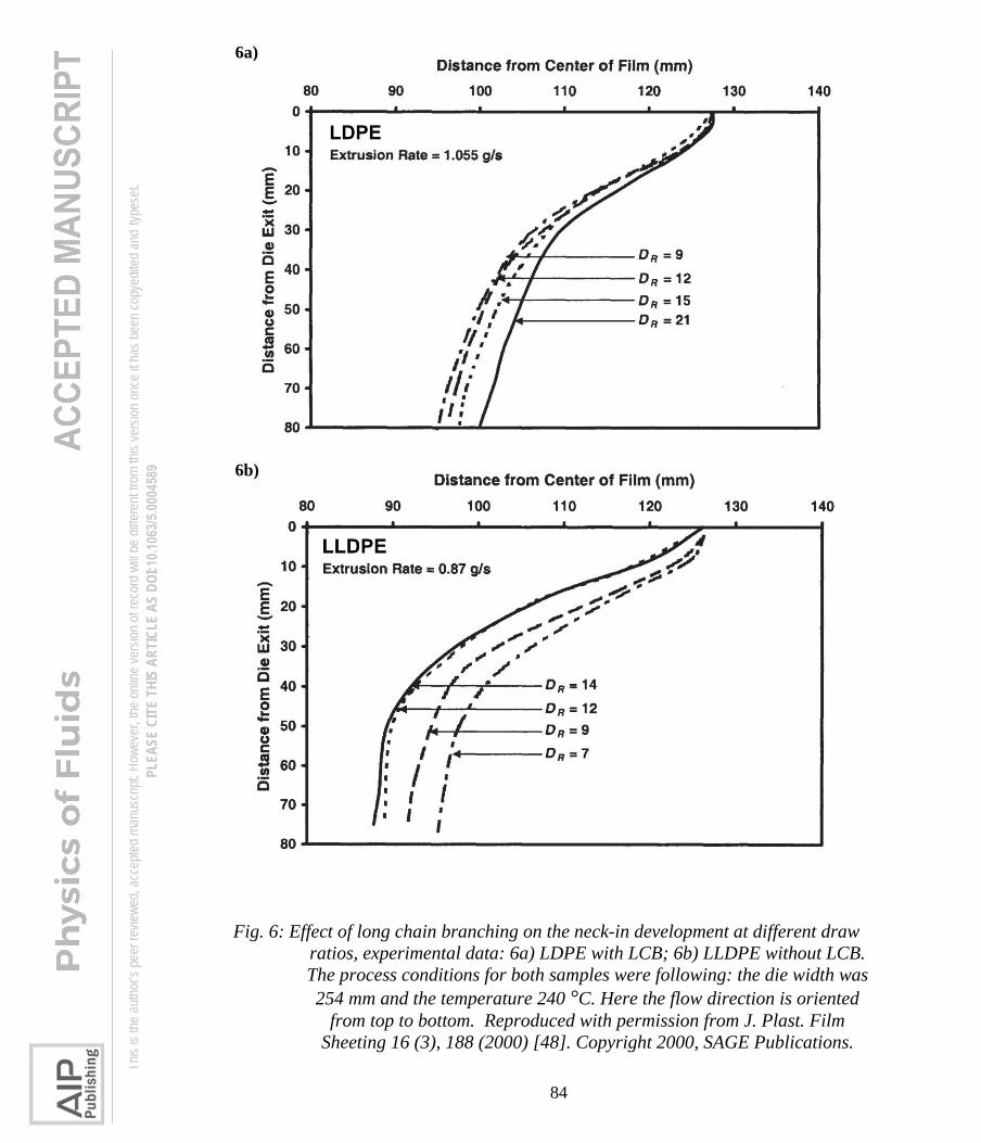
84
Fig. 6: Effect of long chain branching on the neck-in development at different draw
ratios, experimental data: 6a) LDPE with LCB; 6b) LLDPE without LCB.
The process conditions for both samples were following: the die width was
254 mm and the temperature 240 °C. Here the flow direction is oriented
from top to bottom. Reproduced with permission from J. Plast. Film
Sheeting 16 (3), 188 (2000) [48]. Copyright 2000, SAGE Publications.
6a)
6b)
Th
is is
the au
thor’s
peer
revie
wed,
acce
pted m
anus
cript.
How
ever
, the o
nline
versi
on of
reco
rd w
ill be
diffe
rent
from
this v
ersio
n onc
e it h
as be
en co
pyed
ited a
nd ty
pese
t. PL
EASE
CIT
E TH
IS A
RTIC
LE A
S DO
I: 10.1
063/5
.0004
589

85
Fig. 7: Effect of increased long chain branching on the neck-in: 7a) linear
metallocene-catalyzed low-density polyethylene (mLLDPE); 7b) highly
branched low-density polyethylene (LDPE). The process conditions for both
samples were as follows: the die width was 101.6 mm and its gap size 0.57
mm, the take-up length 141.4 mm, the temperature 150 °C, the extrusion
shear rate 1.33 s-1 and the drawdown ratio 10. Here, the flow direction is
oriented from top to bottom. Courtesy of professor Donald G. Baird for his
permission to reprint this figure from [171].
7b)
7a)
Th
is is
the au
thor’s
peer
revie
wed,
acce
pted m
anus
cript.
How
ever
, the o
nline
versi
on of
reco
rd w
ill be
diffe
rent
from
this v
ersio
n onc
e it h
as be
en co
pyed
ited a
nd ty
pese
t. PL
EASE
CIT
E TH
IS A
RTIC
LE A
S DO
I: 10.1
063/5
.0004
589

86
Fig. 8: Visualization of the polymer flow field in the air gap during film casting of
linear metallocene-catalyzed low-density polyethylene (mLLDPE, Mw =
57 200 g/mol, Mw/Mn = 2.26), in which the flow direction is from top to
bottom. The process conditions were as follows: the velocity at the die exit
was 10.7 mm/s, the take-up length equal to 150 mm, the temperature
190 °C. Selected and digitalized from [52].
Th
is is
the au
thor’s
peer
revie
wed,
acce
pted m
anus
cript.
How
ever
, the o
nline
versi
on of
reco
rd w
ill be
diffe
rent
from
this v
ersio
n onc
e it h
as be
en co
pyed
ited a
nd ty
pese
t. PL
EASE
CIT
E TH
IS A
RTIC
LE A
S DO
I: 10.1
063/5
.0004
589
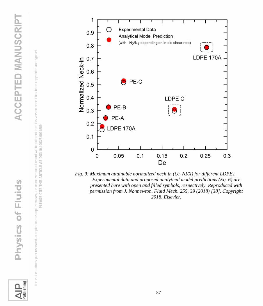
87
Fig. 9: Maximum attainable normalized neck-in (i.e. NI/X) for different LDPEs.
Experimental data and proposed analytical model predictions (Eq. 6) are
presented here with open and filled symbols, respectively. Reproduced with
permission from J. Nonnewton. Fluid Mech. 255, 39 (2018) [38]. Copyright
2018, Elsevier.
Th
is is
the au
thor’s
peer
revie
wed,
acce
pted m
anus
cript.
How
ever
, the o
nline
versi
on of
reco
rd w
ill be
diffe
rent
from
this v
ersio
n onc
e it h
as be
en co
pyed
ited a
nd ty
pese
t. PL
EASE
CIT
E TH
IS A
RTIC
LE A
S DO
I: 10.1
063/5
.0004
589

88
Fig. 10: Schematic illustration of the extrusion film casting process with the indicated
film cross-sectional development (formation of edge-beads) in the air-gap.
The curves within the film represent the borders between the planar
extensional flow (center area) and the uniaxial extensional flow (edge
areas).
Th
is is
the au
thor’s
peer
revie
wed,
acce
pted m
anus
cript.
How
ever
, the o
nline
versi
on of
reco
rd w
ill be
diffe
rent
from
this v
ersio
n onc
e it h
as be
en co
pyed
ited a
nd ty
pese
t. PL
EASE
CIT
E TH
IS A
RTIC
LE A
S DO
I: 10.1
063/5
.0004
589

89
Fig. 11: Evolution of edge-beading at different draw ratios, experimental data for
LLDPE without LCB (corresponding film width profiles are provided in
Figure 6b). Process conditions were following: the die width was 254 mm
and the temperature 240 °C. Reproduced with permission from J. Plast.
Film Sheeting 16 (3), 188 (2000) [48]. Copyright 2000, SAGE Publications.
Th
is is
the au
thor’s
peer
revie
wed,
acce
pted m
anus
cript.
How
ever
, the o
nline
versi
on of
reco
rd w
ill be
diffe
rent
from
this v
ersio
n onc
e it h
as be
en co
pyed
ited a
nd ty
pese
t. PL
EASE
CIT
E TH
IS A
RTIC
LE A
S DO
I: 10.1
063/5
.0004
589
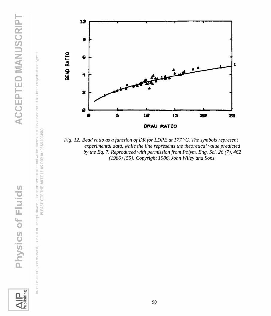
90
Fig. 12: Bead ratio as a function of DR for LDPE at 177 °C. The symbols represent
experimental data, while the line represents the theoretical value predicted
by the Eq. 7. Reproduced with permission from Polym. Eng. Sci. 26 (7), 462
(1986) [55]. Copyright 1986, John Wiley and Sons.
Th
is is
the au
thor’s
peer
revie
wed,
acce
pted m
anus
cript.
How
ever
, the o
nline
versi
on of
reco
rd w
ill be
diffe
rent
from
this v
ersio
n onc
e it h
as be
en co
pyed
ited a
nd ty
pese
t. PL
EASE
CIT
E TH
IS A
RTIC
LE A
S DO
I: 10.1
063/5
.0004
589

91
Fig. 13: Film temperature and width against dimensionless drawing distance for PET
for DR = 10 (A2 experiment) and DR = 20 (A4 experiment), die width =
200 mm and X = 150 mm. The simulations are based on the Newtonian
constitutive equation and 1.5D kinematic model. Reproduced with
permission from Polym. Eng. Sci. 40 (1), 108 (2000) [90]. Copyright 2000,
John Wiley and Sons.
Th
is is
the au
thor’s
peer
revie
wed,
acce
pted m
anus
cript.
How
ever
, the o
nline
versi
on of
reco
rd w
ill be
diffe
rent
from
this v
ersio
n onc
e it h
as be
en co
pyed
ited a
nd ty
pese
t. PL
EASE
CIT
E TH
IS A
RTIC
LE A
S DO
I: 10.1
063/5
.0004
589

92
Fig. 14: Effect of elasticity on the edge-beading for DR = 50 predicted by the 2D film
casting model considering Newtonian and UCM constitutive equations. The
vertical axis represents the dimensionless film thickness (actual thickness
divided by the die gap) and the horizontal axis represents the dimensionless
film width (actual distance from the film center divided by the die width).
Reproduced with permission from J. Nonnewton. Fluid Mech. 79 (2–3), 563
(1998) [28]. Copyright 1998, Elsevier.
Th
is is
the au
thor’s
peer
revie
wed,
acce
pted m
anus
cript.
How
ever
, the o
nline
versi
on of
reco
rd w
ill be
diffe
rent
from
this v
ersio
n onc
e it h
as be
en co
pyed
ited a
nd ty
pese
t. PL
EASE
CIT
E TH
IS A
RTIC
LE A
S DO
I: 10.1
063/5
.0004
589
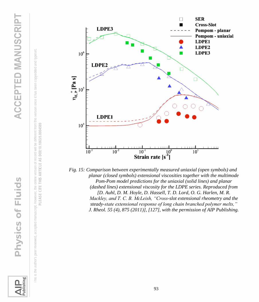
93
Fig. 15: Comparison between experimentally measured uniaxial (open symbols) and
planar (closed symbols) extensional viscosities together with the multimode
Pom-Pom model predictions for the uniaxial (solid lines) and planar
(dashed lines) extensional viscosity for the LDPE series. Reproduced from
[D. Auhl, D. M. Hoyle, D. Hassell, T. D. Lord, O. G. Harlen, M. R.
Mackley, and T. C. B. McLeish, “Cross-slot extensional rheometry and the
steady-state extensional response of long chain branched polymer melts,”
J. Rheol. 55 (4), 875 (2011)], [127], with the permission of AIP Publishing.
Th
is is
the au
thor’s
peer
revie
wed,
acce
pted m
anus
cript.
How
ever
, the o
nline
versi
on of
reco
rd w
ill be
diffe
rent
from
this v
ersio
n onc
e it h
as be
en co
pyed
ited a
nd ty
pese
t. PL
EASE
CIT
E TH
IS A
RTIC
LE A
S DO
I: 10.1
063/5
.0004
589

94
Fig. 16: Normalized film width vs. draw ratio for branched LDPE at three different
air-gaps (squares: X = 10mm; circles: X = 90mm; inverted triangles:
X = 228mm; die width = 100 mm). The symbols represent experimental
data and the lines are predictions based on the XPP constitutive equation
and the 1.5D kinematic model. Reproduced from [H. V. Pol, S. S. Thete, P.
Doshi, and A. K. Lele, “Necking in extrusion film casting: The role of
macromolecular architecture,” J. Rheol. 57 (2), 559 (2013)], [41], with the
permission of AIP Publishing.
Th
is is
the au
thor’s
peer
revie
wed,
acce
pted m
anus
cript.
How
ever
, the o
nline
versi
on of
reco
rd w
ill be
diffe
rent
from
this v
ersio
n onc
e it h
as be
en co
pyed
ited a
nd ty
pese
t. PL
EASE
CIT
E TH
IS A
RTIC
LE A
S DO
I: 10.1
063/5
.0004
589

95
Fig. 17: Normalized film width vs. draw ratio for linear LLDPE at three different air-
gaps (squares: X = 10 mm; circles: X = 90 mm; inverted triangles:
X = 228 mm; die width = 100 mm). The symbols represent experimental
data and the lines are predictions based on the RP-S constitutive equation
and the 1.5D kinematic model. Reproduced from [H. V. Pol, S. S. Thete, P.
Doshi, and A. K. Lele, “Necking in extrusion film casting: The role of
macromolecular architecture,” J. Rheol. 57 (2), 559 (2013)], [41], with the
permission of AIP Publishing.
Th
is is
the au
thor’s
peer
revie
wed,
acce
pted m
anus
cript.
How
ever
, the o
nline
versi
on of
reco
rd w
ill be
diffe
rent
from
this v
ersio
n onc
e it h
as be
en co
pyed
ited a
nd ty
pese
t. PL
EASE
CIT
E TH
IS A
RTIC
LE A
S DO
I: 10.1
063/5
.0004
589

96
Fig. 18: Normalized film width vs. drawing distance at DR = 34.7, die
width = 200 mm and X = 400 mm for linear PP (left) and normalized film
width vs. DR at die width = 100 mm at X = 230 mm for branched LDPE
(right). The symbols represent experimental data and the lines are
predictions based on the modified Leonov constitutive equation and the
1.5D kinematic model. Left figure reproduced from [T. Barborik, and M.
Zatloukal, “Effect of Heat Transfer Coefficient, Draw Ratio and Die Exit
Temperature on the Production of Flat Polypropylene Membranes,” Phys.
Fluids 31 (5), 053101 (2019)], [35], with the permission of AIP Publishing.
Right figure reproduced with permission from Int. J. Heat Mass Transf.
111, 1296 (2017) [37]. Copyright 2017, Elsevier.
Th
is is
the au
thor’s
peer
revie
wed,
acce
pted m
anus
cript.
How
ever
, the o
nline
versi
on of
reco
rd w
ill be
diffe
rent
from
this v
ersio
n onc
e it h
as be
en co
pyed
ited a
nd ty
pese
t. PL
EASE
CIT
E TH
IS A
RTIC
LE A
S DO
I: 10.1
063/5
.0004
589

97
Fig. 19: The planar to uniaxial extensional viscosity ratio predicted by the PTT model
for three different LDPEs plotted as a function of the extensional strain
rate. Reproduced with permission from Polym. Eng. Sci. 50 (1), 22 (2010)
[109]. Copyright 2010, John Wiley and Sons.
Th
is is
the au
thor’s
peer
revie
wed,
acce
pted m
anus
cript.
How
ever
, the o
nline
versi
on of
reco
rd w
ill be
diffe
rent
from
this v
ersio
n onc
e it h
as be
en co
pyed
ited a
nd ty
pese
t. PL
EASE
CIT
E TH
IS A
RTIC
LE A
S DO
I: 10.1
063/5
.0004
589

98
Fig. 20: Comparison of the film edge shapes for three LDPEs with different uniaxial
extensional strain hardening (a-high, b-middle, c-low uniaxial extensional
strain hardening) where die width = 600 mm, and DR was kept the same,
equal to 40 by proper adjusting of vx(0) and vx(X). Left: the role of take-up
velocities (80, 120 and 190 m/min), X = 160 mm; Right: the role of air-gaps
(160, 190 and 220 mm) at the fixed take-up velocity (120 m/min). The
symbols represent experimental data and the lines are predictions based on
the multimode PTT constitutive equation and the 2D kinematic model.
Reproduced with permission from Polym. Eng. Sci. 50 (1), 22 (2010) [109].
Copyright 2010, John Wiley and Sons.
Th
is is
the au
thor’s
peer
revie
wed,
acce
pted m
anus
cript.
How
ever
, the o
nline
versi
on of
reco
rd w
ill be
diffe
rent
from
this v
ersio
n onc
e it h
as be
en co
pyed
ited a
nd ty
pese
t. PL
EASE
CIT
E TH
IS A
RTIC
LE A
S DO
I: 10.1
063/5
.0004
589

99
Fig. 21: Film width vs. drawing distance (left) and final film thickness across the film
width (right) at DR = 32.7, die width = 0.25 m and X = 0.09 m for
branched LDPE (right). Open circles represent experimental data and lines
(or lines with filled circles) are predictions based on the Larson constitutive
equation and the 2D kinematic model. Reproduced with permission from
Polym. Eng. Sci. 41 (9), 1564 (2001) [39]. Copyright 2001, John Wiley and
Sons.
Th
is is
the au
thor’s
peer
revie
wed,
acce
pted m
anus
cript.
How
ever
, the o
nline
versi
on of
reco
rd w
ill be
diffe
rent
from
this v
ersio
n onc
e it h
as be
en co
pyed
ited a
nd ty
pese
t. PL
EASE
CIT
E TH
IS A
RTIC
LE A
S DO
I: 10.1
063/5
.0004
589

100
Fig. 22: Uniaxial extensional viscosity vs. extensional strain rate predicted by the
multimode PTT constitutive equation for LDPE-B: high; Model-A: middle;
Model-B: low uniaxial strain hardening (left) and related predictions for
film width vs. DR including comparison with corresponding Newtonian
predictions by using the 2D kinematic model (right), where DR = 32.7, die
width = 250 mm and X = 90 mm. Reproduced with permission from Polym.
Eng. Sci. 41 (9), 1564 (2001) [39]. Copyright 2001, John Wiley and Sons.
Th
is is
the au
thor’s
peer
revie
wed,
acce
pted m
anus
cript.
How
ever
, the o
nline
versi
on of
reco
rd w
ill be
diffe
rent
from
this v
ersio
n onc
e it h
as be
en co
pyed
ited a
nd ty
pese
t. PL
EASE
CIT
E TH
IS A
RTIC
LE A
S DO
I: 10.1
063/5
.0004
589

101
Fig. 23: Prediction of steady shear viscosity (S), first normal stress difference (N1)
uniaxial (E), planar (P) and biaxial (B) extensional viscosities by using
integral constitutive equation of the K-BKZ type with PSM strain-memory
function (Eq. 56) for IUPAC-LDPE melt A at 150 °C. Solid symbols
visualize experimental data. Solid lines represent model predictions when
parameter in Eq. 56 is allowed to vary with the relaxation time, the dashed
line corresponds to the uniaxial extensional viscosity predicted by using a
single value of . Reproduced with permission from J. Nonnewton. Fluid
Mech. 97 (1), 13 (2001) [145]. Copyright 2001, Elsevier.
Th
is is
the au
thor’s
peer
revie
wed,
acce
pted m
anus
cript.
How
ever
, the o
nline
versi
on of
reco
rd w
ill be
diffe
rent
from
this v
ersio
n onc
e it h
as be
en co
pyed
ited a
nd ty
pese
t. PL
EASE
CIT
E TH
IS A
RTIC
LE A
S DO
I: 10.1
063/5
.0004
589