steady-state modelling of six-phase (multiphase) transmission systems
TRANSCRIPT

six.phase (multiphase) transmission systems S N Tiwari and L P Singh Department of Electrical Engineering, Indian Institute of Technology, Kanpur 208016 (UP), India
The modelling aspects o f a 6-phase (multiphase) power transmission system, which have not previously been fully explored in the literature, are discussed. Initially, repre- sentations o f various components, namely 3-phase/ 6-phase transformers, &phase transmission lines, machines and loads, are developed. A multiphase (or composite 3-phase and &phase) power system is then modelled: in balanced conditions on a single-phase basis, in unbalanced conditions as an equivalent 3-phase system; and also as a composite 3-phase and &phase system retaining the physical Mentities o f the different elements. The procedure is explained with the help o f a numerical example.
Keywords: electric power transmission, power system element modelling, mathematical models
I. Introduction The use of multiphase transmission (MPT) has recently been considered as a viable transmission alternative that can achieve efficient space utilization and increased transmission capability to meet the growing energy demand. Six-phase transmission appears to be the most promising among the multiphase systems. Because of the growing interest in this area, several papers 1-9 have reported on different aspects of this new power transmission technology, including feasibility reliability, fault analysis, protection schemes and conversion of some existing double-circuit 3-phase lines to 6-phase. Use of 6-phase generators for high power applications was pro- posed in a recent contribution 1°. The MPT system, when- ever realized, will always be integrated into an otherwise 3-phase system. Three-phase/6-phase transformers will be required to connect MPT systems to the rest of the network at all levels, namely in stepping up generation voltages to 6-phase, at the primary distribution level and in distribution to 6-phase loads. The transformers necessary for such purposes may be chosen from a variety of connection schemes, including wye/star, delta/star, wye/hexagon, etc. 4 depending upon the specific requirements. Obviously, to analyse an MPT system, adequate representation of the transformers is of major importance. In addition, suitable representations of transmission lines, supply systems and
Received: 22 December 1980
loads will aid the satisfactory analysis and evaluation of the performance of MPT systems.
Willems 7 has modelled wye/star and other types of trans- formers without considering the leakage impedance/admit- tance of the windings. Venkata et aL s and Singh et al. 11 have described a 6-phase transmission line by its phase- impedance matrix. Symmetrical component and Clarke's component transformations of multiphase systems have been developed by Venkata et al. s and Willems 9, relying mainly on analogy and intuitive reasoning. Singh et al. 11, ,2 have presented power invariant symmetrical and Clarke's component transformations on rigorous mathematical bases employing group theoretic techniques. ABCD-para- meters and 3-phase equivalents of 6-phase transmission systems were obtained by Willems 7. Tiwari and Singh 8 proposed the lattice-equivalent representation of 3-phase/ 6-phase transformers and the zr representation of a 6-phase transmission line suitable for unbalanced network analysis. In the present paper, a realistic and improved representa- tion of transformers is derived, taking leakage impedance/ admittance into consideration. Using the improved model of a transformer, the ABCD-parameter and 3-phase equivalent of an MPT system are obtained, and the results given in Reference 7 are shown to be the special cases of the pro- posed derivations. The representation of a 6-phase genera- tor, suitable for balanced as well as unbalanced network analysis, is developed, and various descriptions of multi- phase loads and their 3-phase equivalents are also discussed. Using the representation of 6-phase elements presented in the paper and the usual 3-phase elements 13-~s, three model- ling schemes of a multiphase or composite system are obtained. Finally, representations of a sample system are obtained: on a single-phase basis, as an equivalent 3-phase system, and as a mixed 3-phase and 6-phase system retain- ing the physical identities of 3-phase and 6-phase elements. The modelling schemes presented may be effectively used in the analysis of a multiphase system both for balanced and unbalanced network situations, especially for load flow and short-circuit studies.
II. Transformer representations
I1.1 Nonideal transformer representation Consider the wye/star transformer shown in Figure 1. A nominal ratio transformer may be represented by an ideal
10(1 ~ I A O / ~ 1 ~ / 0 0 / r 1 0 ( ~ 1 0 / ' 1 NQ ~ N ~ /~t~ ~ 1Q~t9 R l l t t a r I M n r t h ~ I~_n I P l l h l i ~ h ~ r ~ } I t r l I:l~rtrlr~l Pnw~r ~ Enerav Systems
II
-O d B o o b
O e CO- . . . . 0 c
Figure 1. Wye/star connection scheme for 3-phase/6-phase conversion
IA Ao
Ic C 0
B o I°
f' Y If
l '" -1 F ~ ~ f ~ ' - 4 Y i°
Y __r._o b' I 1- b
~- v2 "2 C' Y Ic
d' Y ~1 I - "r d <? d
q Y I- 2 ' ©e
Figure 2. Schematic representation of nominal ratio wye/star transformer (p.u.)
transformer in series with the equivalent p.u. leakage admittance y of the windings, as depicted in Figure 2. The voltage and current relationships are:
1NI T v ' 6 V ; 6 = NV~ V~ =2"" --p (1)
I/~ = [I'Ki'TI62"" "p Ip6 = NI 3 (2)
V'6__ V6 7_ [Z] 16 (3 ) p - -p
where
v;6= [v',, v;, v;, vS, v;, v'A"
V 6 : I r a , Vb, Vc , Vd, r e , Vf] r
v g = [vA, v~, Vc] r
16p = [Ia,Ib, Ic,Id, Ie , l f] T
j~, : [&, &, &] r
N T = i 0 0 -- 1
0 1 0
--1 0 0 1 0 -
1
and
[z] = 6 x 6 diagonal matrix = [8] -1
From equations (3) and (1), 13 is obtained as follows:
I~ = [y] [N] V~ -- [y] V 6 (4)
and from equations (2) and (4), I~ is obtained as follows:
I~, = {[Nlr[y] IN] V~ --½[Nlr[y] V~ (5)
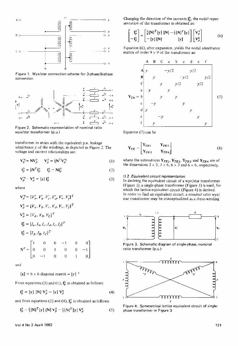
Changing the direction of the currents 16, the nodal repre- sentation of the transformer is obtained as:
[_ I;] = r ½[N]T[y] INI- INI tyl] [vS 1 I6J L-[y] [N] [y] j Lv6J
(6)
Equation (6), after expansion, yields the nodal admittance matrix of order 9 x 9 of the transformer as:
A
B
C
a
YrR = b
C
d
e
f
A B C a b c d e f
y -y /2 y/2
y -y/2 y/2
y y/2 -y/2 --y y
--y
Y
Y
--y
Y
Y
Y
Y
Y
(7)
Equation (7) can be
= [ Y r m YrRz]
YrR LYTR 3 YTR4J (8)
where the submatrices YTRI, YTR2, YTR3 and YTR4 are of the dimensions 3 x 3, 3 x 6, 6 x 3 and 6 x 6, respectively.
11.2 Equivalent circuit representation In deriving the equivalent circuit of a wye/star transformer (Figure 1), a single-phase transformer (Figure 3) is used, for which the lattice-equivalent circuit (Figure 4) is derived. In order to find an equivalent circuit, a nominal ratio wye/ star transformer may be conceptualized as a three-winding
is I:1 Y
V, V; •
jc~
Figure 3. Schematic diagram of single-phase, nominal ratio transformer (p.u.)
i
,7 c.
Y
Y
i r q f ' C U ~ f ~ Y
Figure 4. Symmetrical lattice equivalent circuit of single- phase transformer in Figure 3
Vol 4 No 2 April 1982 121

transformer having:
• a primary winding P with terminals labelled A, B, C and N,
• a secondary winding S with terminals labelled a, c, e, and n,
a tertiary winding T with terminals labelled d,f , b and n with the neutrals of S and T joined together, lfyps, ypr andYsT are usual short-circuit p.u. admittances of the two windings indicated by the subscript with the third winding open, an equivalent circuit can be assembled by arranging three wye/wye equivalent circuits in parallel in turn. By matching the parallel sides in the identifica- tion of single-phase units, A-N with a-n, A-N with d-n etc., the connection table showing the admittance con- nected between different nodes is obtained, as given in Table 1.
The nodal admittance matrix of the transformer can then be assembled from the given values ofyps, YPr and Ysr. For a case where the short-circuit parameters become equal toy ' , the neutrals of the two sides are grounded, and the windings S and T are identical in all respects except that they are displaced by 180 °, the nodal admittance matrix becomes
YTR =
A
C I
a - -y '
b
C
d y'
e
f
B C a b c d e f
--y'
2/ 2/
2/ y' 2y'
--y' 2y'
y'
_y ' y'
y' - y '
y l
y'
y'
y ' 2y'
- -y ' y ' 2y'
y ' y ' 2y'
In deriving the above two representations of the wye/star transformers, the effect of magnetizing core and saturation effects are neglected. A careful examination of YrR in equations (7) and (9) shows that they are not the same. In fact, the representation of the equivalent circuit is more
(9)
Table 1. C o n n e c t i o n table for wye / s tar transformer wi th equiva lent w i n d i n g s P , S and T
Admittance Between nodes
YPS + YPT N-A YPS + 2YsT n-a YPT + 2YSr n -d YPT -- YPS n - A .
YPS A-a --YPs N-a --Ypr A-d YPT N-d --Y sr a-d,
N - B , N-C n-c, n-e n-f, n-b n-B, n-C B-c, C-e N-c, N-e B-f, C-b N-f, N-b c-f, e-b
precise than that of the nonideal transformer because it considers the mutual coupling of the windings (S and T L which are placed on the same core, whereas no such coupling has been considered in the nonideal case. However, the advantages of the nonideal representation are that it is simple to obtain and is reasonably accurate. The above procedure can be extended to other types of transformers, including delta/star and wye/hexagon.
I I I . Six-phase (multiphase) transmission line representations
III. 1 Phase-impedance represen tation One of the basic objectives of an MPT system is the effi- cient use of space, which can be maximized by placing the conductors on the vertices of a regular hexagon forming the circular array 2. Although significant improvement in space utilization is possible even with conventional configurations. complete transposition of multiphase lines is very difficult to achieve in practice. However, the 6-phase system has been found to be better balanced than the double-circuit, 3-phase system for the same conductor configurations 2. In the case of a circular array with the phases lying on the vertices of a regular hexagon, this may be further improved and the transposition may not be necessary.
An untransposed 6-phase line, possessing cyclic symmetry is described by its phase-impedance matrix Z~ as
~-Zs Zm5 Zrn4 Zm3 Zm2 Zm I
Zml Zs Zm5 Zrn4 Zm3 Zm2
Zm2 Zml Zs grns Zm4 Zm3
Zrn3 Zm2 21111 Zs ZrnS Zm4
Zm4 Zm3 Zm2 Zrnl Zs Zm5
Zms Zm4 Zm3 Zm2 Zml Z s,
~I0)
As pointed out above, several versions of symmetrical and Clarke's component transformations s' 9 for &phase systems have been suggested. All these transformations were obtained mainly by analogy and intuitive reasoning. They lack power invariancy, a desirable feature for power-system problems. However, Singh et al. u have developed power-invariant, symmetrical-component transformations that exploit symmetries inherent in multiphase power networks from group theoretic considerations. Z~, as given by equation (10) and possessing cyclic (or rotational symmetry), can be diagonalized by the linear power-invariant, complex- transformation matrix Ts6 as:
1 Ts6 =;77
-1 1 1
1 o~* --o~
1 --oe - - a * 1
1 - -1 1 - - t
1 --c~* - - a 1
1 a -ce* 1
1 l 1
--1 -o~* c~
1 --1
---O:* - O~
---&' O~*
( l l )
If a complete transposition of conductors (though physi- cally too difficult to realize) is made, then, by exploiting the cyclic (or rotational) and reflection symmetries of the transmission network, a power invariant, linear and real
122 Electrical Power & Energy Systems
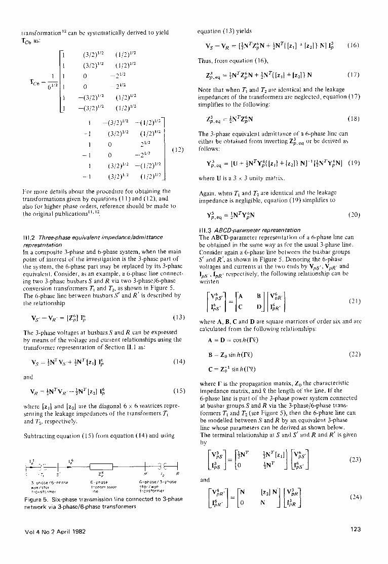
transformation ~2 can be systematically derived to yield equation (13) yields
1 TC6 =
TC6 as:
(3/2) 1/z (1/2) '/2
(3/2) '/2 (1/2) '/2
0 --2 '/2
0 --2 '/z
- - (3/2) w2 (1/2) '/z
- - (3/2) wE (1/2) l/z
1 --(3/2) 1/2 --(1/2)'/2Z
-- 1 (3/2) wE (1/2) '/2
1 0 2 w2
--1 0 --21/2
1 (3/2) '/2 - - ( l / 2 ) '/2
-- 1 --(3/2) ':2 (1/2) '/2
For more details about the procedure for obtaining the transformations given by equations (11) and (12), and also for higher phase orders, reference should be made to the original publications ~'' ~2.
(12)
111.2 Three-phase equivalent impedance/admittance rep resen tation In a composite 3-phase and 6-phase system, when the main point of interest of the investigation is the 3-phase part of the system, the 6-phase part may be replaced by its 3-phase equivalent. Consider, as an example, a 6-phase line connect- ing two 3-phase busbars S and R via two 3-phase/6-phase conversion transformers T~ and T2, as shown in Figure 5. The 6-phase line between busbars S' and R ' is described by the relationship
vs,-vR, : [G]g (13)
The 3-phase voltages at busbars S and R can be expressed by means of the voltage and current relationships using the transformer representation of Section II.1 as:
V s = ~NTVs'+ ½NT[z,] l~ (14)
and
1 IM T~f 1 l~.l T 6 VR = ~ ' " " R ' - - ~ ' " [Z2] Ip (15)
where [Zl] and [z2] are the diagonal 6 x 6 matrices repre- senting the leakage impedances of the transformers T1 and T2, respectively.
Subtracting equation (15) from equation (14) and using
I - ~ I i '; 'r, .5' Zp 6 R' T 2 R
3 "phase / ~ - Dhose 6 - phase 6 - phase / 3 - phase w y e / s t a r ? ronsmlssio~ s t a r / w y e Transformer l ine t r a n s f o r m e r
Figure 5. Six-phase transmission line connected to 3-phase network via 3-phase/6-phase transformers
VS VR = 1 T 6 +[Z2] } N] 3 (16) -- [~N ZpN + ½NT{ [ZI] Ip
Thus, from equation (16),
Z~,e q : 1NTZ~ N + 1 T ~N {[z,] +[zz]} N (17)
Note that when Ta and T= are identical and the leakage impedances of the transformers are neglected, equation (17) simplifies to the following:
Z~),eq 1 T 6 (18) = ~N ZpN
The 3-phase equivalent admittance of a 6-phase line can either be obtained from inverting Zg,eq or be derived as follows:
3 = [U+½NTy~{[Zl] +[z:]} N]-'[½NTy~N] (19) Yp, eq
where U is a 3 x 3 unity matrix.
Again, when T1 and/ '2 are identical and the leakage impedance is negligible, equation (19) simplifies to
Y~9,eq ----- 2"'I-I~Tv 6~--p'" (20)
111.3 ABCD-parameter representation The ABCD-parameter representation of a 6-phase line can be obtained in the same way as for the usual 3-phase line. Consider again a 6-phase line between the busbar groups S' and R', as shown in Figure 5. Denoting the 6-phase voltages and currents at the two ends by VpS', VpR' and lps, , IpR, respectively, the following relationship can be written
[v d J-I: ;] (21)
where A, B, C and D are square matrices of order six and are calculated from the following relationships:
A = D = cosh(F~)
B = Zo sin h ( r£) (22)
C = Zo' sin h(F£)
where F is the propagation matrix, Zo the characteristic impedance matrix, and ~ the length of the line. If the 6-phase line is part of the 3-phase power system connected at busbar groups S and R via the 3-phase/6-phase trans- formers TI and T2 (see Figure 5), then the 6-phase line can be modelled between S and R by an equivalent 3-phase line whose parameters can be derived as shown below. The terminal relationship at S and S' and R and R' is given by
I V~ s ] ![~ WT ½ NT[z ' ] ] IV~sq
l~s J= ½ N r J Llgs'] (23)
and
I~,.' J [O N [zd N J
(24)
Vol 4 No 2 April 1982 123

From equations (21), (23) and (24), the terminal quantities of busbar groups S and R can be related as follows:
VgS] = I I~ ]T ½ NT[Z1]]
IgS J ½N T J L ~
Iz IN] Vv q N Li~,a j
(25)
which can be written as,
[ V ~ s ] = ~ Ae3q Beaq] [ V~R] (26)
,g, j Lc: D qJ L,gR J In view of the fact that A = D and [zx] and [z2] are diagonal matrices, equation (25), after simplification, yields
A~q = ~NTAN + ~NTizl] CN
B~q = ½NTBN + ½NTA [z~ +z2] N+ ½NT[z~] C[z2] N
(27)
Ce3q = ½NTCN
De3q = ½NTDN + ½NTC [z2] N
Note that the 3-phase equivalent parameters Ae3q and De3q are no longer equal. In the special case when leakage impedances of T1 and T2 are neglected, equation (27) simplifies to the following, as obtained in Reference (7):
Ae3q = ½NTAN
B~q = ½NTBN
C~q = ½NTCN (28)
Deaq = ½NTDN
111.4 Nominal or distr ibuted (equivalent) 7r representation A 6-phase transmission line can be represented using the nominal or distributed (equivalent) rr model. Consider a 6-phase line connected between busbar groups S' and R' at the sending end and receiving end respectively (Figure 5). The equation describing the terminal currents and
Is G 5
26 C, G
Figure 6.
/
-- - - : 4
Schematic diagram of 6-phase generator
- ~ 2
© 3
© 4
voltages can be written as
= ~ Sh --Y¢ (29) L R,J k-w Y~*½Ys Lv R'J
where Y¢ = [z~]-' and ½Ys. is the equivalent capacitive susceptances at each set of the busbars S' and R'.
The matrix Zg is related to its symmetrical component 6 matrix Zcomp as
Z 6 = [Ts6 ] 6 [Zcomp] [Ts6*] r (30)
and for a completely transposed line Z6comp is a purely diagonal matrix. Note that when the capacitive susceptances are neglected, equation (29) is simplified to
,asl V Vv d I-v: Lv:.,]
(31)
IV. Six-phase machine (generator) representation Six-phase generators have been proposed for high power applications by Hanna et al. 10 The feasibility of using high phase order machines is a topic that is still in its infancy and needs a considerable amount of further investigation. However, these machines, if ever realized, may be modelled and analysed without too much difficulty. Consider the 6-phase synchronous generator, depicted in Figure 6, which is grounded through a reactance YN" The detailed representation incorporating the imbalance in the machine is given by
[ xp, -£c, -% --Y2 6yl 0
-- YTo 0 ( YN + 6Yc
(32)
where
Z~ is a 6 × 6 order phase impedance matrix of the generator
Y I = [ I c~ --a* --1 --a c~*]ryl
Y 2 = [ 1 c : - ~ 1 - c : ~]y~
Y0 = [1 1 1 1 1 1 ] T y 0
y 1 is the positive sequence admittance of the generator
Y0 is the zero sequence admittance of the generator
V~ is the vector of 6-phase voltages
E1 is the induced voltage of phase 1
V u is the induced voltage of the neutral
S is the total complex power
The above description of the machine is based on the fact that the internal induced voltages of the generator are balanced, whereas its terminal voltages depend on internal machine impedances and imbalance in machine currents. Due to the imbalance, each phase power is not equal to one sixth of the total power, prohibiting the calculation of
124 Electrical Power & Energy Systems

phase currents. However, for a balanced machine, equation (32) takes the form
[ I ~ l F Y ¢ - - Y o )1 IV61 I Yl E 6 ] = - P + (33) k i N ] L-Yo r (6yo + YN VN L--yoEN.]
where
I~ is the vector of machine phase currents
I N is the neutral current
E 6 is the vector of induced voltages of the machine
The phase impedance matrix Z 6 of the machine is related to its symmetrical component matrix by equation (30).
V. Representation of loads on a multiphase system Loads on a 6-phase system can be represented by constant admittances/impedances as balanced or unbalanced, as the case may be. Loads, in the form of 6-phase machines, may be adequately represented by equation (32) or equation (33), as detailed in Section IV. In some cases, it may be necessary to represent a 6-phase load by an equivalent 3-phase load for carrying out the analysis of a composite system as a 3-phase system. This can be achieved as out- lined below.
Consider a 6-phase load connected to a supply system via a 3-phase/6-phase transformer, as shown in Figure 7. Recalling the voltage and current relationship of transformer equations (1)-(3) in Section Il. 1, and the representation of the 6-phase load as
[/~ ~ 6 6 YL Vp
the current I~ can be written as
13 = 1/~ITv6'~.IX:3 I~jTv6 NI~ ~l'* = L l , V p - - gl'q * L [Z]
(34)
(35)
Rearranging equation (35) yields
i~rTv6 3 (36) I~ = [U + 2,, --L [Z] N] -1 [½NTy~,N] Vp
Hence, the equivalent 3-phase load is given by
l'~i T v 6 1 T 6 = [sN YLN] (37) Y~,eq [U + 3,, - L [ z ] N I - '
Similarly, the 3-phase equivalent impedance of a 6-phase impedance load can either be obtained by inverting ya L,eq or be derived to be equal to
Z 3 1/MTs76 L,eq = gl, "t~L -t- [Z]} N (38)
3- phase 3-phose/6-phose Co-phase load busbar wye/stor
~rranstormer
Figure 7. Schematic diagram of 6-phase load connected to 3-phase busbars
L5
Figure 8. Single-line diagram of sample multiphase power system network
In the special case where leakage impedances of transformer windings are neglected, equations (37) and (38) are simpli- fied to the following, as obtained in Reference (7):
y3 !~xrTv6 ~r (39) L,eq = 2 x" =L x"
and
I~T76 ~T (40) Z~,eq = 2 l, LL,',
Equations similar to (37)-(40) can be derived for loads connected via other types of transformers.
Vl. Modelling schemes for multiphase systems and numerical example Three modelling schemes for a multiphase (or composite) system will be described with the help of a typical sample power system network, depicted in Figure 8, with the following data:
• 6-phase transmission line LI:
Zo = j0.25 Z 1 = Z2 = Z3 = Z4 = Zs = j0.08
• 3-phase transmission line L2:
Zo = j0.25 Z1 = Z2 = j0.08
• 3-phase transmission line L3:
Zo = j0.50 Z1 = Z2 = j 0 . t 6
• 3-phase/6-phase wye/star transformers T1, T2:
Z p s = Z p T = N E T = j0.05
leakage impedance/phase = j0.10
VI. 1 Single phase representation To obtain the representation of the system shown in Figure 8, the 6-phase line L1 is first converted into an equivalent 3-phase line. Using equation (19), the equivalent admittance is obtained:
3 [ --j5.555 0 0
Y~,eq = Y/~I = 0 --j5.555 0
L 0 0 --j5.555
(41)
making use of the relationship
Y~ = [Ts6 ] [Vc6omp] [Ts6*] T (42)
Vol 4 No 2 April 1982 125

and the computed value of Y¢
-~11.080 1.416
1.416 --11.080
1.416 1.416 Y¢ = j
1.416 1.416
1.416 1.416
1.416 1.416
1.416
1.416
1.416
-- 11.080
1.416
1.416
1.416
1.416
- 11.080
1.416
1.416
1.416
1.416 1.416 q
1.416 1.416
1.416 1.416
1.416 1.416
- 1 1 . 0 8 0 1.416
1.416 --11.080
(43)
The nodal admittance description of lines L2 and L3 using relationship (42) for the 3-phase system is obtained as:
Y~2 =J
---9.666 2.833 2.8331
2.833 --9.666 2.833
2.833 2.833 --9.666
(44)
and
--4.833 1.416 1.416-]
V~'.3 =J / 1.416 --4.833 1.416 /
L 1.416 1.416 - 4 . 8 3 3 A
(45)
Assuming balanced system conditions, the mutual coupling between the phases of the 3-phase elements is neglected.
4 I 0 0 7
-P YL~I 05 Y L23 8
3 06 9
Y~3
Figure 9. Schematic diagram of sample system showing phase busbar numbering sequence intended for 3-phase representation
Table 2. 3-phase connect ion table for network in Figure 9
Terminating busbar groups
N~ N2 Nodal admittance matrix
1 "~ 3 4, 5, 6 Y}A 1, 2, 3 7, 8. 9 Y~,3 4, 5, 6 7, 8, 9 Y},2
JC
2
19 U, I'
Figure 10. Schematic diagram of sample system showing phase busbar numbering sequence intended for mixed 3-phase and 6-phase representation
This yields the nodal admittance matrix of the sample system on a single-phase basis:
10.388 5.555 4.833-]
Y = j 5.555 --15.221 9.666 I /
4.833 9.666 -- 14.499_]
(46)
V I.2 Three-phase representation To illustrate the 3-phase representation, the sample system of Figure 8 is redrawn with the busbar numbering sequence shown schematically, as depicted in Figure 9. Noting that a nodal admittance matrix can be formed from the connec- tion table of the network branch admittances using the relationship 13
y = CTyb C (47)
where C is the appropriate connection matrix and Yb the branch admittance matrix, then, with the help of equation (47) and Figure 9, the 3-phase connection table --2 yields the system admittance matrix of order 9 x 9:
-~ 10.833 1.416 1.416 5.555
1.416 -- 10.833 1.416 0.000
1.416 1.416 -10 .833 0.000
5.555 0.000 0.000 -15 .221
0.000 5.555 0.000 2.833
0.000 0.000 5.555 2.833
4.833 --1.416 - 1 . 4 1 6 9.666
--1.416 4.833 - 1 . 4 1 6 - 2 . 8 3 3
--1.416 --1.416 4.833 --2.833
0.000 4.833 - 1 . 4 1 6 - I . 4 1 6 -
0.000 - 1 . 4 1 6 4.833 - 1.416
5.555 - 1 . 4 1 6 - 1 . 4 1 6 4.833
2.833 9.666 - 2 . 8 3 3 - 2 . 8 3 3
2.833 - 2 . 8 3 3 9.666 --2.833
-15 .221 --2.833 --2.833 9.666
- 2 . 8 3 3 - 14.499 4.049 4.249
- 2 . 8 3 3 4.249 -- 14.499 4.249
9.666 4.249 4.249 - 14.499
0.000
5.555
0.000
2.833
-15 .221
2.833
- 2 . 8 3 3
9.666
- 2 . 8 3 3
(48)
Y=j
196 Electrical Power & Energy Systems

V l.3 Mixed 3-phase and 6-phase representation To visualize the mixed 3-phase and 6-phase representation retaining the physical identities of the different elements, the sample system in Figure 8 is redrawn in Figure 10 to show the busbar numbering sequence. Inspection of Figure 10 yields the multiphase connection table 3 showing the connection of the various elements between the groups of busbars and also the branch admittance matrices. The system nodal admittance matrix assembled from the con- nection table 3 is obtained as follows:
V I I . Conclusion The modelling of various components of a multiphase (6-phase) power system, suitable for steady state analysis, has been discussed. Three-phase/6-phase transformers, which link the multiphase components with the rest of the network, have been represented in two ways for a wye/star connection scheme: the nonideal representation is simple and has been used extensively in deriving several useful results; the equivalent circuit representation is more accurate and particularly suitable for rigorous representa-
1 . . . 3 4 . . . 9 10 . . .15 16.• .18 19. . .21
y =
1 • Y(1T)I + Y~3 3
4 • Y(1T) 3 6
10
15
16
18
19 • _ y 3
L3 21
Y(1T) 2
y(I)TR4 + Y~II• V~,12
Y~A3 Y~A4 + Y(2T) 1
Y(2T) 3
Y(2T) 2
-v ,3
Y(2T)4 + Y~2 -Y~2
-Y~2 Y~2 + Y~3
(49)
Substituting the numerical values of different submatrices, a 21 x 21 order nodal admittance matrix will be obtained. In some studies, such as short-circuit studies of unbalanced networks, a supplemented nodal admittance matrix is required. This requires the loads and supply system to be represented in nodal admittance form• Loads can be incor- porated by modifying the appropriate principal diagonal or block diagonal elements, as the case may be. Similarly, the system nodal admittance matrix is assembled by including the nodal admittance submatrices of the supply systems by appropriately modifying the relevant elements.
tion of the overall system intended for unbalanced net- work analysis. The transmission line model, for both short and long lengths, is discussed. Consideration is also given to the problem of transposition of multiphase lines and sym- metrical and Clarke's component transformations•
The 3-phase equivalent representation of multiphase lines is suitable for deriving the single phase and 3-phase repre- sentations of composite power networks. Multiphase trans- mission line ABCD-parameters and their 3-phase equivalents are particularly useful for utilities employing ABCD-para-
Table 3. Connection table of multiphase network in Figure 10
Terminating busbar groups
N1 N2 Element
Branch admittance matrix Remarks
1-3 4-9
4-9 10-15
10-15 16-18
16-18 19-21
1-3 19-21
Wye/star transformer T1 YOrR)
6-phase line L 1 Y~,I
Star/wye transformer/'2 Y~)
3-phase line L2 Y~2
3-phase line L3 Y~3
With submatrices Y(1TR) v YO:r):, v (n and yO) of I T R 3 T R 4 appropriate dimensions (see equation (8))
With submatrices Y~u, Y~12, 6 6 YLIa' YL14 of 6 x 6 dimension each (see equation (31))
With submatrices Y(~R)1 , Y(2TR) 2, Y(2TR) a and Y(2TR) 4 of appropriate dimensions
Equation (44)
Equation (45)
Vol 4 No 2 April 1982 127

meter descriptions for transmission system analysis pro- 5 grams. The 7r representation used in Section IIIA may be effectively used to represent long lines for unbalanced network analysis. The representation of a 6-phase generator, which may be realized in future, has been discussed, and 6 multiphase loads and their 3-phase equivalents have been derived using a realistic representation of the transformer connecting them to 3-phase busbars. Finally, a sample system is considered for obtaining its representations: in balanced 7 conditions on a single phase basis; in unbalanced conditions on an equivalent 3-phase basis; and on a mixed 3-phase and 6-phase basis keeping the physical identities of the different elements. With these representation schemes, a multiphase 8 (or composite ) system can be effectively analysed for load flow and faults in both balanced and unbalanced network conditions,
Although the effects of magnetic core and saturation are 9 not taken into account, the representation of transformers is quite adequate for the studies for which it is intended. Also, only wye/star transformers with nominal ratios have been used to derive the various results, but the procedures 10 may easily be extended to other types, either with nominal turns ratios or with tappings.
V I I I . References 1 Barthold, L O and Barnes, H C 'High-phase order trans-
mission' Electra Vol 24 (1972) pp 139-153
Stewart, J R and Wilson, D D 'High-phase order trans- mission - a feasibility analysis. Part I: Steady state considerations. Part I1: Over voltages and insulation requirements' IEEE Trans. Power Appar. & Syst. Vot PAS-97 (November/December 1978) pp 2300-2317
3 Venkata, S S, Bhatt, N B and Guyker, W C 'Six phase (multiphase) power transmissions: concept and reliabi- l i ty aspects' Paper A 76504-I, IEEE PES Summer Meeting (1976)
Guyker, W C et al. '138 kV six-phase transmission system feasibility' presen ted at American Power Conference (1978)
11
12
13
14
15
Bhatt, N Bet al. 'Six-phase (multiphase) power trans- missions: fault analysis' IEEE Trans. Power Appar. & Syst. Vol PAS-96 (May/June 1977) pp 758-767
Nanda, S P, Tiwari, S N and Singh, L P 'Fault analysis of six-phase system' Electr. Power Syst. Res. J. Vol 4 No 3 (July 1981) pp 201-211
Willems, J L 'The analysis of interconnected three- phase and polyphase power systems' Paper A-79504-2, IEEE PES Summer Meeting (1979)
Tiwari, S N and Singh, L P 'Representation of three- phase and rnultiphase (six-phase) power transmission systems in phase coordinates' communicated to Proc. Inst. E/ectr. Eng.
Willems, J L 'Fault analysis and component schemes for polyphase power systems' Int. J. Electr. Power & Energy Syst. Vol 2 No 1 (January 1980) pp 43-48
Hanna, R A, Macdonald, D C and Allen, P G H 'The six:phase generator and its associated transformer' Proc. 14th UPEC Loughborough University of Tech- nology, UK Paper 5A .5 (April 1978)
Singh, L P and Sinha, V P 'Steady state analysis of multiphase power system network using group theoretic techniques' IFAC Symp. Computer App/ications in Large Scale Power Systems New Delhi Vol II (August 1979) pp 160-167
Singh, L P, Chaube, A C and Sinha, V P 'Generalized Clarke's component transformations for grounded n-port networks'J. Inst. Eng. (India) Vol 60-E1 6 (June 1980) pp 291-292
Laughton, M A 'The analysis of unbalanced polyphase networks by the method of phase coordinates. Part |: System representation in phase frame of referen~ '~ .............. Proc. Inst. Electr. Eng. Vol 115 (August 1968) pp 1163-1172
Roy, L 'Generalized polyphase fault analysis program: calculation of cross country fault' Proc. Inst. Electr. Eng. Vol 126 (October 1979) pp 995-1000
Chen, M and Dillon, W E 'Power system modelling' Proc. IEEE Vol 62 (1974) pp 901-915
19£ Electrical Power & Energy Systems