steel piers technical design manual 89 ec p s t eel p ie r ™ d e s ign chapter 5 steel piers...
TRANSCRIPT

Page 89
EC
P S
tee
l P
ier™
De
sig
n
Chapter 5
Steel Piers
Technical Design Manual PPB-166 Slab Bracket System
PPB-200 Under Footing Pier System
PPB-250 Under Footing Pier System
PPB-300 ECP Steel Pier™
System
PPB-350 ECP Steel Pier™
System
PPB-400 ECP Steel Pier™
System
Earth Contact Products, LLC reserves the right to change design features, specifications and products without notice, consistent with our efforts toward continuous product improvement. Please check with Engineering Department, Earth Contact Products to verify that you are
using the most recent information and specifications.
ECP Steel Piers™ Technical Service Manual
2013-09
© 2013 Earth Contact Products, L.L.C.
All rights reserved Page 90
Introduction
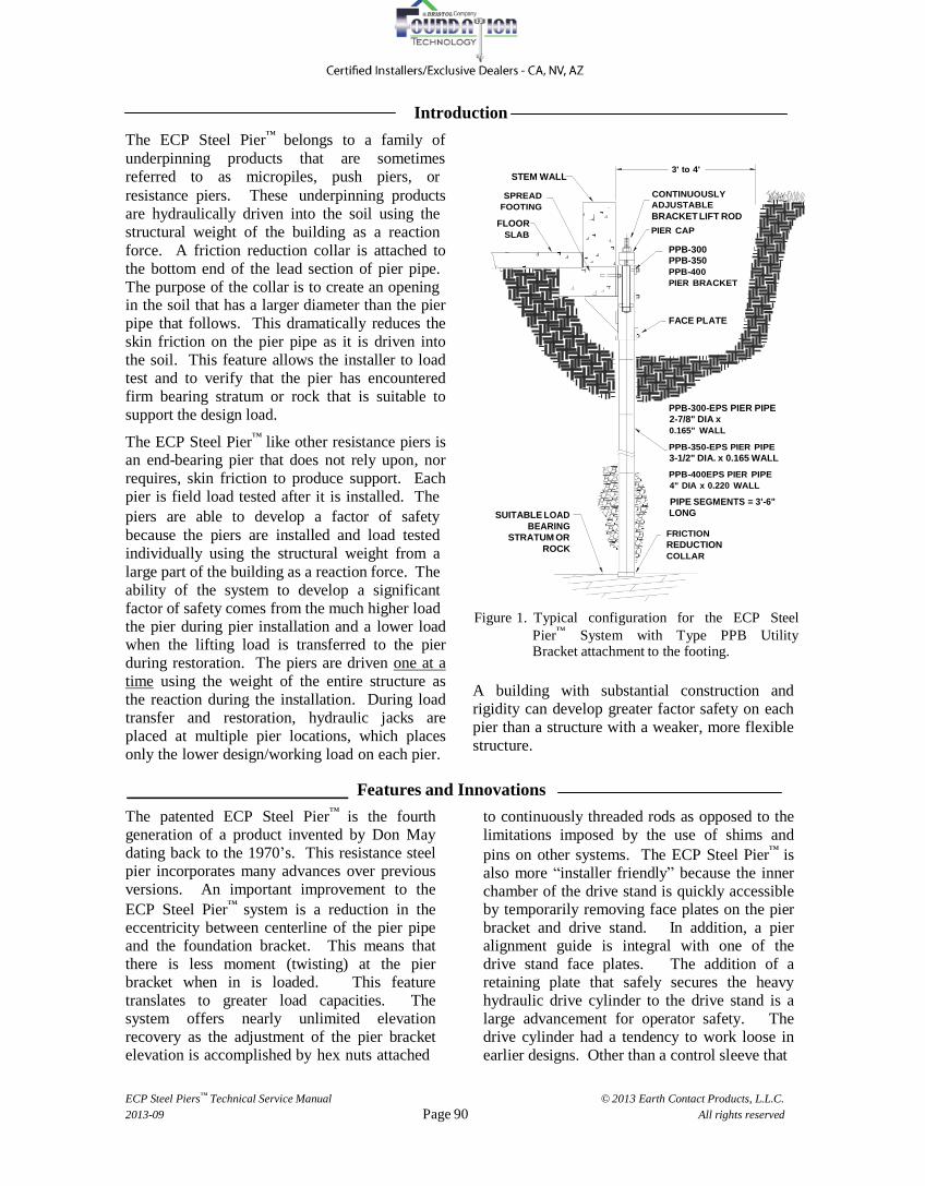
The ECP Steel Pier™
belongs to a family of
underpinning products that are sometimes
referred to as micropiles, push piers, or
STEM WALL
3' to 4'
resistance piers. These underpinning products
are hydraulically driven into the soil using the
structural weight of the building as a reaction
force. A friction reduction collar is attached to
the bottom end of the lead section of pier pipe.
The purpose of the collar is to create an opening in the soil that has a larger diameter than the pier
pipe that follows. This dramatically reduces the
skin friction on the pier pipe as it is driven into
the soil. This feature allows the installer to load
test and to verify that the pier has encountered
firm bearing stratum or rock that is suitable to
support the design load.
The ECP Steel Pier™
like other resistance piers is an end-bearing pier that does not rely upon, nor
requires, skin friction to produce support. Each
pier is field load tested after it is installed. The
SPREAD
FOOTING
FLOOR
SLAB
CONTINUOUSLY
ADJUSTABLE
BRACKET LIFT ROD
PIER CAP
PPB-300 PPB-350
PPB-400
PIER BRACKET
FACE PLATE
PPB-300-EPS PIER PIPE
2-7/8" DIA x
0.165" WALL
PPB-350-EPS PIER PIPE
3-1/2" DIA. x 0.165 WALL
PPB-400EPS PIER PIPE
4" DIA x 0.220 WALL
PIPE SEGMENTS = 3'-6"
piers are able to develop a factor of safety
because the piers are installed and load tested
individually using the structural weight from a
large part of the building as a reaction force. The
ability of the system to develop a significant
SUITABLE LOAD
BEARING
STRATUM OR
ROCK
LONG FRICTION
REDUCTION
COLLAR
factor of safety comes from the much higher load the pier during pier installation and a lower load when the lifting load is transferred to the pier
during restoration. The piers are driven one at a
time using the weight of the entire structure as
the reaction during the installation. During load
transfer and restoration, hydraulic jacks are
placed at multiple pier locations, which places
only the lower design/working load on each pier.
Figure 1. Typical configuration for the ECP Steel
Pier™
System with Type PPB Utility Bracket attachment to the footing.
A building with substantial construction and
rigidity can develop greater factor safety on each
pier than a structure with a weaker, more flexible
structure.
Features and Innovations
The patented ECP Steel Pier™
is the fourth generation of a product invented by Don May
dating back to the 1970’s. This resistance steel pier incorporates many advances over previous
versions. An important improvement to the
ECP Steel Pier™
system is a reduction in the eccentricity between centerline of the pier pipe and the foundation bracket. This means that
there is less moment (twisting) at the pier bracket when in is loaded. This feature
translates to greater load capacities. The system offers nearly unlimited elevation
recovery as the adjustment of the pier bracket elevation is accomplished by hex nuts attached
to continuously threaded rods as opposed to the
limitations imposed by the use of shims and
pins on other systems. The ECP Steel Pier™
is also more “installer friendly” because the inner
chamber of the drive stand is quickly accessible by temporarily removing face plates on the pier
bracket and drive stand. In addition, a pier alignment guide is integral with one of the
drive stand face plates. The addition of a retaining plate that safely secures the heavy
hydraulic drive cylinder to the drive stand is a
large advancement for operator safety. The drive cylinder had a tendency to work loose in
earlier designs. Other than a control sleeve that

ECP Steel Piers™ Technical Service Manual
2013-09
© 2013 Earth Contact Products, L.L.C.
All rights reserved Page 91
EC
P S
tee
l P
ier™
De
sig
n
is only used on the PPB-350, all of the pier
brackets are designed to securely align and
guide the pier pipe without additional tools.
Another innovation on the ECP PPB-300 &
PPB-350 Steel Pier™
Systems is the patented “Inertia Sleeve”. This state of the art method
of increasing the moment of inertia (stiffness) of the pier pipe and the “Inertia Sleeve” strengthens the coupled joints, which is unmatched in the industry. The pier pipe and “Inertia Sleeve” combination produces a more rigid pier system with a higher moment of inertia (stiffness) than the pier pipe alone.
The “Inertia Sleeve” does not carry any of the
axial compressive pier load; the function of this
product is only to increase pier stiffness in
weak soils to prevent buckling. (See Figure 3,
next page)
The “Inertia Sleeve” consists of a piece of pipe
that fits snugly inside the existing pier pipe. At
one end the “Inertia Sleeve” has a nine inch
long coupling that fits through, and spans
across, the coupled pier joint. The “Inertia
Sleeve” is installed concurrent with the pier
pipe installation and only takes the time
necessary to pick up the “Inertia Sleeve”
product and to let it drop by gravity into the
current pier section prior to installing the next
section of pier pipe.
The installed cost of this pier strengthening
product is hardly more than the purchase price
of the “Inertia Sleeve” product, yet it creates a
stiffer pier system that is more resistant to
buckling when installed through weak soil.
Product Benefits
Ultimate-Limit Capacities: Up to 115,000 lb.
Proof Test Loads: Up to 86,000 lb.
Standard Lift – 4” Fully Adjustable
Greater Lift Capability With Optional Longer Bracket Rods
Installs From Outside or Inside the Structure
Installs With Portable Hydraulic
Equipment
Installs With Little or No Vibration
Friction Reduction Collar On Lead Pier
Section Reduces Skin Friction
Installs To Rock or Verified End Bearing
Stratum
100% of Piers Are Field Load Tested to
Verify Capacity During Installation
Manufacturer’s Warranty
Pier Installation Sequences
Quiet vibration free hydraulic equipment is used to install ECP Steel
Piers™
. All installation equipment is portable and can be carried in a wheelbarrow. After all of the piers are installed and load tested, the
structure can be immediately restored
by transferring the structural load to
the piers. There are no days wasted
waiting for concrete to cure and no
soil to transport from the site. A
measured factor of safety is verified,
as the piers are 100% load tested to a
force greater than the actual working load prior to being put in service.
DRIVE CYLINDER
DRIVE STAND
FOUNDATION STEMWALL
FOUNDATION
FOOTING
INSTALLED PIER AND BRACKET
Projects are usually completed in
days, not weeks. Should geologic
conditions change, the piers can be
easily inspected, tested and/or
adjusted.
STARTER PIER PIPE
Figure 2. Typical Steel Pier
™ Installation with Utility Bracket.

ECP Steel Piers™ Technical Service Manual
2013-09
© 2013 Earth Contact Products, L.L.C.
All rights reserved Page 92
PPB Utility Bracket Installation
The following nine steps illustrate the typical installation
procedure for the PPB-300, PPB-350 or PPB-400 Utility
Bracket. Figure 2 shows a structure with a spread footing.
The detail on the left side of Figure 2 illustrates the
configuration used when installing the resistance pier
system and driving the pier pipe. On the right side of
Figure 2 is the configuration of the installed pier system
following the transfer of the structural load to the pier.
Please contact ECP engineering department for ECP
Typical Specifications that provide the specific and
detailed product installation requirements and procedures.
1. Site survey: Pier placements are determined and
locations of all underground utilities are verified.
2. Excavation: Small excavations are dug for access at
PPB Utility Bracket Components
PIER
CAP
BRACKET
ROD & NUT
BRACKET
each placement location. The excavation required at
the foundation is usually about 3 feet square.
3. Preparation of the foundation: The footing is
notched (if required) to situate the pier bracket under
the stem wall. The bearing area under the footing is
chipped a smooth and level condition and the face of
the stem wall is adjusted to vertical (plumb) at the
point of bracket attachment.
4. Utility Bracket Attachment: The utility bracket is
secured to the footing using two anchor bolts. Then
the drive stand and the hydraulic cylinder are mounted
to the bracket. (Shown on left side of Figure 2.)
5. Pier Pipe Installation: The piers may be installed
from outside or inside the structure. The pier pipe is
advanced into the soil using a small portable high-
pressure hydraulic pump. The pier pipe is 3-1/2 feet
long so low overhead clearance is not a problem
during installation. Pier installation continues until
rock or suitable bearing is encountered below the
unstable soil near the surface.
6. Proof Load Test: Every pier is load tested to insure
that rock or other firm bearing is verified to be
CONTROL
SLEEVE
(PPB-350 ONLY)
EXTENSION
PIER
SECTION
STARTER
PIER
SECTION
FRICTION
REDUCTION
COLLAR
FACE
PLATE
INERTIA SLEEVE
INSTALLS INSIDE
PIER SECTIONS
(OPTIONAL SOME
PRODUCTS)
substantial enough to withstand a load greater than
required to restore and support the structure. The
structure provides the reaction force for installing and
testing. Typically Factor of Safeties from 1.25 to 3.0
can typically be generated.
7. Preparations for Restoration: Once all piers have
been installed, load tested, and the installation data
recorded; lifting head assemblies and hydraulics are
placed at the placements, which are connected to one
or more manifolds and hydraulic hand pumps.
8. Restoration: Under careful supervision, the
structural load is transferred from the failing soil
under the foundation to the steel pier system. The
Figure 3. Component configuration for
typical PPB-300, PPB-350 &
PPB-400 Utility Brackets
structure is gently and evenly lifted
to the specified design elevation.
The nuts at the pier caps are
secured at each placement and the
lifting equipment is removed.
(Please see Figure 1.)
9. Clean Up: The soil that was
excavated at each pier placement
location is replaced and compacted.
The site is left clean and neat.
ECP Steel Piers™ Technical Service Manual
2013-09
© 2013 Earth Contact Products, L.L.C.
All rights reserved Page 93
EC
P S
tee
l P
ier™
De
sig
n
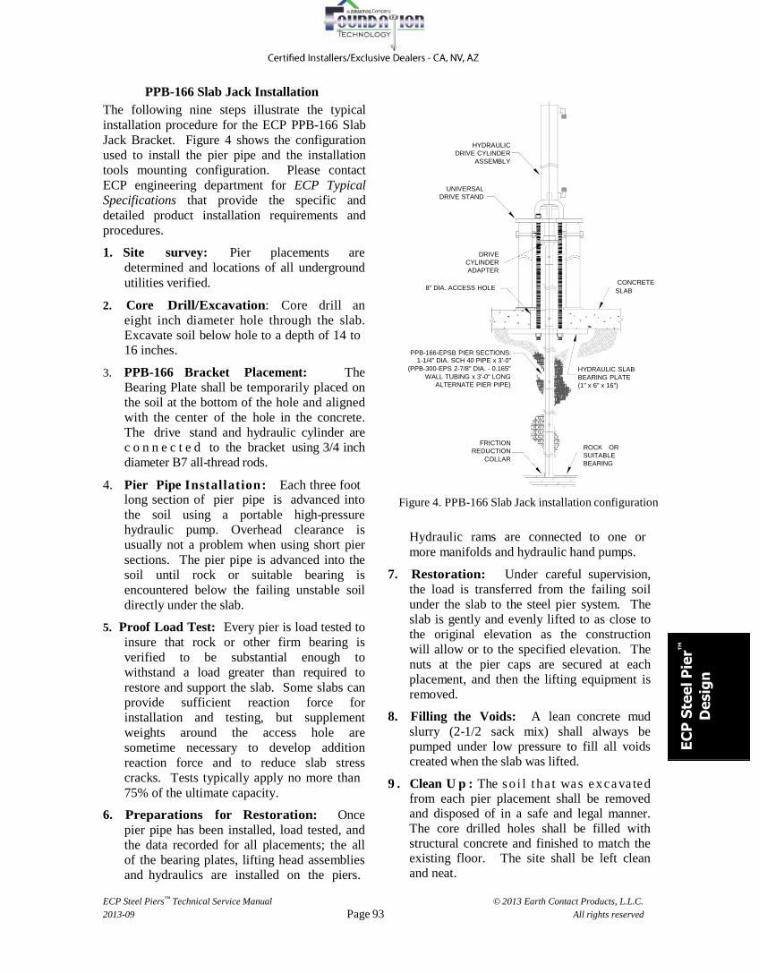
PPB-166 Slab Jack Installation
The following nine steps illustrate the typical
installation procedure for the ECP PPB-166 Slab
Jack Bracket. Figure 4 shows the configuration
used to install the pier pipe and the installation
tools mounting configuration. Please contact
ECP engineering department for ECP Typical
Specifications that provide the specific and
detailed product installation requirements and
procedures.
1. Site survey: Pier placements are
determined and locations of all underground
utilities verified.
2. Core Drill/Excavation: Core drill an
eight inch diameter hole through the slab.
Excavate soil below hole to a depth of 14 to 16 inches.
HYDRAULIC
DRIVE CYLINDER
ASSEMBLY
UNIVERSAL
DRIVE STAND
DRIVE
CYLINDER
ADAPTER
CONCRETE 8" DIA. ACCESS HOLE SLAB
PPB-166-EPSB PIER SECTIONS:
1-1/4" DIA. SCH 40 PIPE x 3'-0"
3. PPB-166 Bracket Placement: The
Bearing Plate shall be temporarily placed on
the soil at the bottom of the hole and aligned
with the center of the hole in the concrete.
The drive stand and hydraulic cylinder are
c o n n e c t e d to the bracket using 3/4 inch
diameter B7 all-thread rods.
4. Pier Pipe I n s t a l l a t i o n : Each three foot
(PPB-300-EPS 2-7/8" DIA. - 0.165"
WALL TUBING x 3'-0" LONG
ALTERNATE PIER PIPE)
FRICTION
REDUCTION
COLLAR
HYDRAULIC SLAB
BEARING PLATE
(1" x 6" x 16")
ROCK OR
SUITABLE
BEARING
long section of pier pipe is advanced into
the soil using a portable high-pressure
hydraulic pump. Overhead clearance is
usually not a problem when using short pier
sections. The pier pipe is advanced into the
soil until rock or suitable bearing is
encountered below the failing unstable soil
directly under the slab.
5. Proof Load Test: Every pier is load tested to
insure that rock or other firm bearing is
verified to be substantial enough to
withstand a load greater than required to
restore and support the slab. Some slabs can
provide sufficient reaction force for
installation and testing, but supplement
weights around the access hole are
sometime necessary to develop addition
reaction force and to reduce slab stress
cracks. Tests typically apply no more than
75% of the ultimate capacity.
6. Preparations for Restoration: Once
pier pipe has been installed, load tested, and
the data recorded for all placements; the all
of the bearing plates, lifting head assemblies
and hydraulics are installed on the piers.
Figure 4. PPB-166 Slab Jack installation configuration
Hydraulic rams are connected to one or
more manifolds and hydraulic hand pumps.
7. Restoration: Under careful supervision,
the load is transferred from the failing soil
under the slab to the steel pier system. The
slab is gently and evenly lifted to as close to
the original elevation as the construction
will allow or to the specified elevation. The
nuts at the pier caps are secured at each
placement, and then the lifting equipment is
removed.
8. Filling the Voids: A lean concrete mud
slurry (2-1/2 sack mix) shall always be
pumped under low pressure to fill all voids
created when the slab was lifted.
9 . Clean U p : The s o i l t h a t wa s e x c a va te d from each pier placement shall be removed and disposed of in a safe and legal manner.
The core drilled holes shall be filled with structural concrete and finished to match the existing floor. The site shall be left clean and neat.

ECP Steel Piers™ Technical Service Manual
2013-09
© 2013 Earth Contact Products, L.L.C.
All rights reserved Page 94
14
"
ECP Steel Pier™ – Product Configurations
A. PPB-300 Utility Bracket B. PPB-350-400 Utility Bracket C. PPB-350-400-WM Wall Bracket
1-7/8" PIER
OFFSET
UNLIMITED LIFT
WITH LONGER
11 3/4"
5 1/16"
UNLIMITED LIFT
WITH LONGER
BRACKET RODS
PIER OFFSET
2 1/2"
13"
6 7/8"
PIER OFFSET 2 5/8"
4" STD. LIFT
UNLIMITED LIFT
WITH LONGER BRACKET RODS
15 1/4"
4" STD. LIFT
7"
BRACKET RODS
BEFORE LIFT
AFTER LIFT
11/16" DIA.
4 HOLES
4" STD. LIFT
7 1/2"
BEFORE
LIFT
AFTER
LIFT
11/16" DIA.
4 HOLES
BEFORE LIFT
AFTER LIFT
1--1/8" DIA. 8 HOLES
6" 7"
16 "
14 1/2"
2-7/8" DIA. x
0.165 WALL
CONTROL
SLEEVE
(MODEL
350 ONLY)
18"
CONTROL
SLEEVE
(MODEL 10 3/8" 9 3/4" PIER PIPE
12"
4" DIA. x
0.220 WALL
PIER PIPE 9 7/8"
3-1/2" DIA. x
0.165 WALL
PIER PIPE
4 5/8 " 350 ONLY)
Ultimate-Limit Bracket Capacity
(MODEL 400) (MODEL 350) Ultimate-Limit Capacity Std. Bracket: 107,000 pounds
79,000 pounds Ultimate-Limit Bracket Capacity
99,000 pounds
PPB-400 WM HD Bracket 115,000 pounds (Not Shown)
D. PPB-350-EP2 & PPB-350-EP4 Eccentric Bracket E. PPB-350-MP2 Micro Pile 4-1/2" PIER OFFSET
14"
7 1/2"
4" STD. LIFT
BEFORE
LIFT
AFTER
LIFT
6-1/2" PIER OFFSET
16"
7 1/2"
4" STD. LIFT
UNLIMITED LIFT
WITH LONGER
BRACKET RODS
BEFORE
LIFT
AFTER
LIFT
13"
11/16" DIA.
4 HOLES
8"
CONCRETE TILT
UP WALL
SPREAD
FOOTING 3' to 4'
CONTINUOUSLY
18 1/2"
FLOOR SLAB ADJUSTABLE
BRACKET LIFT ROD
PIER CAP
MODEL PPB-EP2
ECCENTRIC PIER
BRACKET
FACE
PLATE
4" DIA. x 0.220 Wall
PIER SLEEVE x 42"
LONG
12"
PB-350 EP2 PPB- 350 EP4
9 7/8"
3-1/2" DIA. x 0.165
WALL PIER PIPE
PIER SLEEVE
x 3'-6" LONG WITH
Ultimate-Limit Bracket Capacity: EP2 - 68,000 lb – EP4 - 55,000 lb
F. PPB-166 Slab Jack Bracket Assembly G. PPB-200 & PPB-250
Under Footing Bracket
COUPLING
GROUT
COLUMN
COLLAR
8" DIA. ACCESS HOLE
PILE CAP ASSY
1" x 3-1/2" x 7"
CONCRETE
SLAB
HOLLOW
MICROPILE
SHAFT
PIER SECTIONS:
1-1/4" DIA. SCH 40 PIPE x 3'-0"
(ALTERNATE 2-7/8" DIA. - 0.165"
WALL TUBING x 3'-0" LONG)
HYDRAULIC SLAB
BRACKET ASSY
(1" x 6" x 16"
BEARING PLATE)
SUITABLE
BOND
ZONE
SACRIFICIAL
DRILL BIT
FRICTION
REDUCTION
COLLAR
ROCK OR
SUITABLE
BEARING
Ultimate-Limit Bracket
Capacities:
PPB-200 - 50,000 pounds
Ultimate-Limit Bracket Capacity Ultimate-Limit Bracket Capacity: 22,000 lb
(Pier Pipe Sold Separately)
PPB-250 - 54,000 pounds
(PPB-250 similar, not shown)
68,000 pounds
ECP Steel Piers™ Technical Service Manual
2013-09
© 2013 Earth Contact Products, L.L.C.
All rights reserved Page 95
EC
P S
tee
l P
ier™
De
sig
n
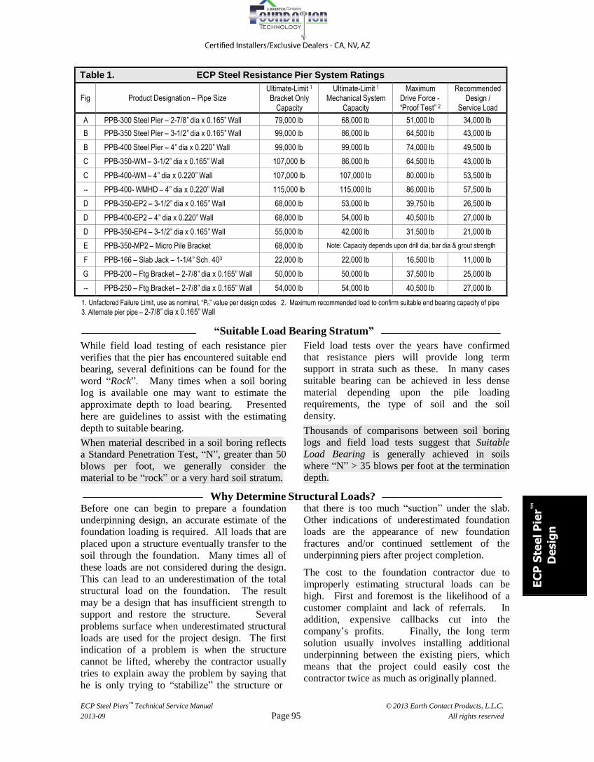
Table 1. ECP Steel Resistance Pier System Ratings
Fig
Product Designation – Pipe Size
Ultimate-Limit 1
Bracket Only Capacity
Ultimate-Limit 1
Mechanical System Capacity
Maximum Drive Force - “Proof Test” 2
Recommended Design /
Service Load A PPB-300 Steel Pier – 2-7/8” dia x 0.165” Wall 79,000 lb 68,000 lb 51,000 lb 34,000 lb
B PPB-350 Steel Pier – 3-1/2” dia x 0.165” Wall 99,000 lb 86,000 lb 64,500 lb 43,000 lb
B PPB-400 Steel Pier – 4” dia x 0.220” Wall 99,000 lb 99,000 lb 74,000 lb 49,500 lb
C PPB-350-WM – 3-1/2” dia x 0.165” Wall 107,000 lb 86,000 lb 64,500 lb 43,000 lb
C PPB-400-WM – 4” dia x 0.220” Wall 107,000 lb 107,000 lb 80,000 lb 53,500 lb
-- PPB-400- WMHD – 4” dia x 0.220” Wall 115,000 lb 115,000 lb 86,000 lb 57,500 lb
D PPB-350-EP2 – 3-1/2” dia x 0.165” Wall 68,000 lb 53,000 lb 39,750 lb 26,500 lb
D PPB-400-EP2 – 4” dia x 0.220” Wall 68,000 lb 54,000 lb 40,500 lb 27,000 lb
D PPB-350-EP4 – 3-1/2” dia x 0.165” Wall 55,000 lb 42,000 lb 31,500 lb 21,000 lb
E PPB-350-MP2 – Micro Pile Bracket 68,000 lb Note: Capacity depends upon drill dia, bar dia & grout strength
F PPB-166 – Slab Jack – 1-1/4” Sch. 403 22,000 lb 22,000 lb 16,500 lb 11,000 lb
G PPB-200 – Ftg Bracket – 2-7/8” dia x 0.165” Wall 50,000 lb 50,000 lb 37,500 lb 25,000 lb
-- PPB-250 – Ftg Bracket – 2-7/8” dia x 0.165” Wall 54,000 lb 54,000 lb 40,500 lb 27,000 lb
1. Unfactored Failure Limit, use as nominal, “Pn” value per design codes 2. Maximum recommended load to confirm suitable end bearing capacity of pipe
3. Alternate pier pipe – 2-7/8” dia x 0.165” Wall
“Suitable Load Bearing Stratum”
While field load testing of each resistance pier
verifies that the pier has encountered suitable end
bearing, several definitions can be found for the
word “Rock”. Many times when a soil boring
log is available one may want to estimate the
approximate depth to load bearing. Presented
here are guidelines to assist with the estimating
depth to suitable bearing.
When material described in a soil boring reflects a Standard Penetration Test, “N”, greater than 50
blows per foot, we generally consider the
material to be “rock” or a very hard soil stratum.
Field load tests over the years have confirmed that resistance piers will provide long term
support in strata such as these. In many cases
suitable bearing can be achieved in less dense
material depending upon the pile loading
requirements, the type of soil and the soil
density.
Thousands of comparisons between soil boring
logs and field load tests suggest that Suitable
Load Bearing is generally achieved in soils
where “N” > 35 blows per foot at the termination
depth.
Why Determine Structural Loads? Before one can begin to prepare a foundation
underpinning design, an accurate estimate of the
foundation loading is required. All loads that are
placed upon a structure eventually transfer to the
soil through the foundation. Many times all of
these loads are not considered during the design.
This can lead to an underestimation of the total
structural load on the foundation. The result
may be a design that has insufficient strength to
support and restore the structure. Several
problems surface when underestimated structural
loads are used for the project design. The first
indication of a problem is when the structure
cannot be lifted, whereby the contractor usually
tries to explain away the problem by saying that
he is only trying to “stabilize” the structure or
that there is too much “suction” under the slab.
Other indications of underestimated foundation
loads are the appearance of new foundation
fractures and/or continued settlement of the underpinning piers after project completion.
The cost to the foundation contractor due to
improperly estimating structural loads can be
high. First and foremost is the likelihood of a
customer complaint and lack of referrals. In
addition, expensive callbacks cut into the
company’s profits. Finally, the long term
solution usually involves installing additional
underpinning between the existing piers, which
means that the project could easily cost the
contractor twice as much as originally planned.
ECP Steel Piers™ Technical Service Manual
2013-09
© 2013 Earth Contact Products, L.L.C.
All rights reserved Page 96
GYPSUM INSULATED BOARD CONCRETE
BLOCK
BRICK
VENEER
BRICK
VENEER
W O O D FRAME
STUCCO VENEER
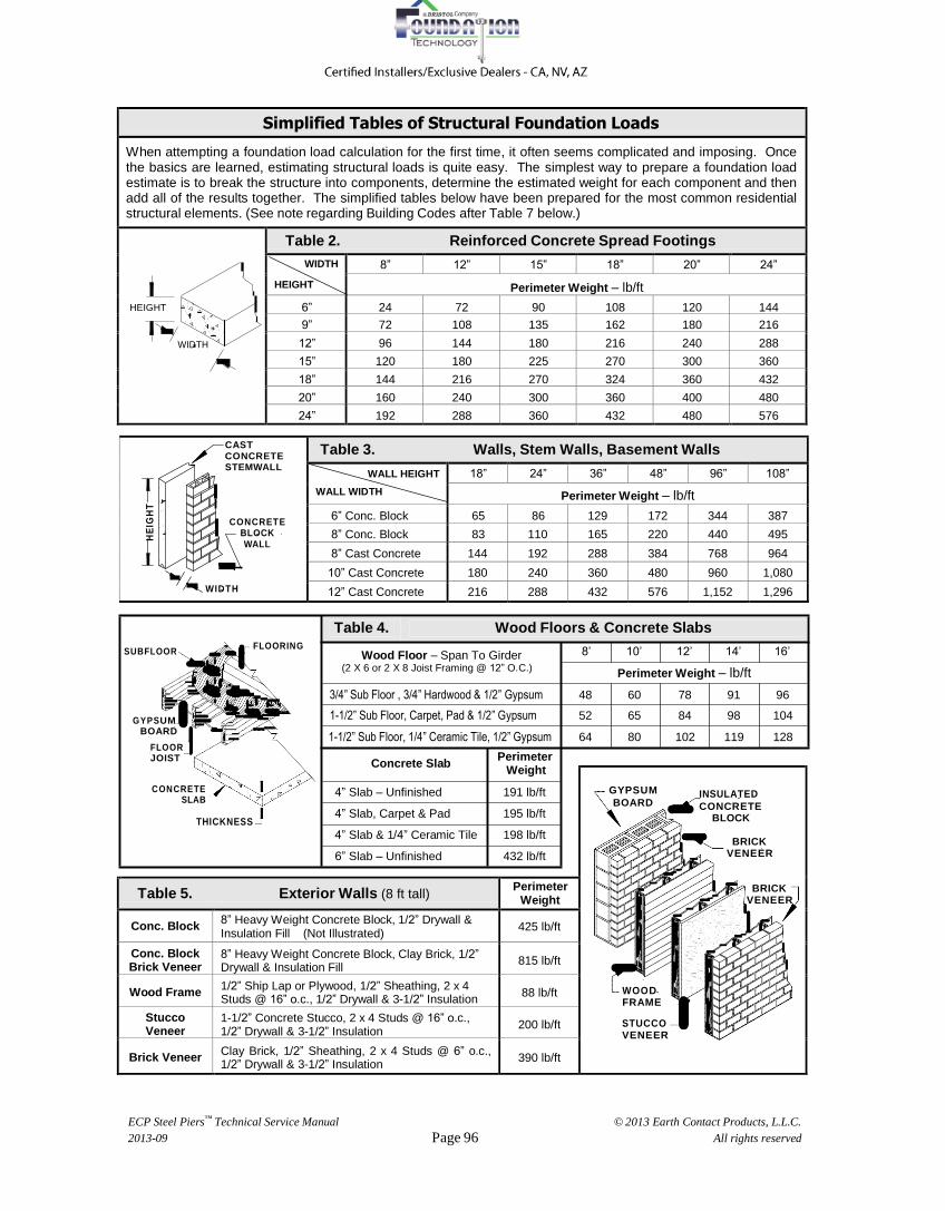
Table 5. Exterior Walls (8 ft tall) Perimeter Weight
Conc. Block 8” Heavy Weight Concrete Block, 1/2” Drywall & Insulation Fill (Not Illustrated)
425 lb/ft
Conc. Block Brick Veneer
8” Heavy Weight Concrete Block, Clay Brick, 1/2” Drywall & Insulation Fill
815 lb/ft
Wood Frame 1/2” Ship Lap or Plywood, 1/2” Sheathing, 2 x 4 Studs @ 16” o.c., 1/2” Drywall & 3-1/2” Insulation
88 lb/ft
Stucco Veneer
1-1/2” Concrete Stucco, 2 x 4 Studs @ 16” o.c., 1/2” Drywall & 3-1/2” Insulation
200 lb/ft
Brick Veneer Clay Brick, 1/2” Sheathing, 2 x 4 Studs @ 6” o.c., 1/2” Drywall & 3-1/2” Insulation
390 lb/ft
HE
IGH
T
Simplified Tables of Structural Foundation Loads
When attempting a foundation load calculation for the first time, it often seems complicated and imposing. Once the basics are learned, estimating structural loads is quite easy. The simplest way to prepare a foundation load estimate is to break the structure into components, determine the estimated weight for each component and then add all of the results together. The simplified tables below have been prepared for the most common residential structural elements. (See note regarding Building Codes after Table 7 below.)
HEIGHT
WIDTH
Table 2. Reinforced Concrete Spread Footings
WIDTH
HEIGHT 8” 12” 15” 18” 20” 24”
Perimeter Weight – lb/ft 6” 24 72 90 108 120 144 9” 72 108 135 162 180 216 12” 96 144 180 216 240 288 15” 120 180 225 270 300 360 18” 144 216 270 324 360 432 20” 160 240 300 360 400 480 24” 192 288 360 432 480 576
CAST CONCRETE STEMWALL
CONCRETE BLOCK WALL
WI DTH
Table 3. Walls, Stem Walls, Basement Walls
WALL HEIGHT
WALL WIDTH 18” 24” 36” 48” 96” 108”
Perimeter Weight – lb/ft 6” Conc. Block 65 86 129 172 344 387 8” Conc. Block 83 110 165 220 440 495 8” Cast Concrete 144 192 288 384 768 964
10” Cast Concrete 180 240 360 480 960 1,080 12” Cast Concrete 216 288 432 576 1,152 1,296
Table 4. Wood Floors & Concrete Slabs
SUBFLOOR FLOORING
Wood Floor – Span To Girder
8’ 10’ 12’ 14’ 16’
G Y P S UM BOARD
FLOOR JOIST
CONCRETE
SLAB
THICKNESS
(2 X 6 or 2 X 8 Joist Framing @ 12” O.C.) Perimeter Weight – lb/ft
3/4” Sub Floor , 3/4” Hardwood & 1/2” Gypsum 48 60 78 91 96
1-1/2” Sub Floor, Carpet, Pad & 1/2” Gypsum 52 65 84 98 104
1-1/2” Sub Floor, 1/4” Ceramic Tile, 1/2” Gypsum 64 80 102 119 128
Concrete Slab Perimeter
Weight
4” Slab – Unfinished 191 lb/ft
4” Slab, Carpet & Pad 195 lb/ft
4” Slab & 1/4” Ceramic Tile 198 lb/ft
6” Slab – Unfinished 432 lb/ft
ECP Steel Piers™ Technical Service Manual
2013-09
© 2013 Earth Contact Products, L.L.C.
All rights reserved Page 97
EC
P S
tee
l P
ier™
De
sig
n
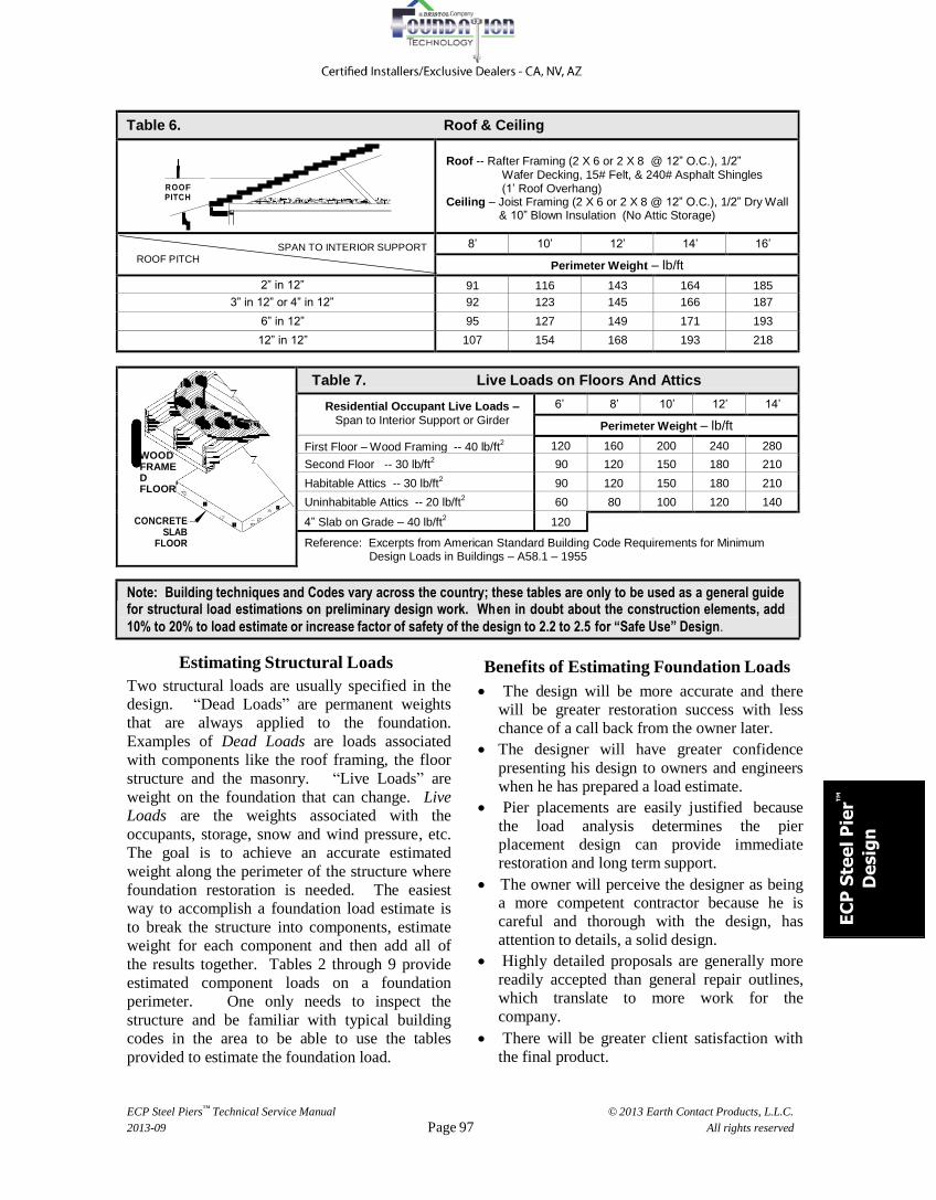
Table 6. Roof & Ceiling
R O O F PITCH
Roof -- Rafter Framing (2 X 6 or 2 X 8 @ 12” O.C.), 1/2”
Wafer Decking, 15# Felt, & 240# Asphalt Shingles (1’ Roof Overhang)
Ceiling – Joist Framing (2 X 6 or 2 X 8 @ 12” O.C.), 1/2” Dry Wall & 10” Blown Insulation (No Attic Storage)
SPAN TO INTERIOR SUPPORT ROOF PITCH
8’ 10’ 12’ 14’ 16’
Perimeter Weight – lb/ft 2” in 12” 91 116 143 164 185
3” in 12” or 4” in 12” 92 123 145 166 187 6” in 12” 95 127 149 171 193 12” in 12” 107 154 168 193 218
WOOD FRAMED FLOOR
CONCRETE
SLAB FLOOR
Table 7. Live Loads on Floors And Attics
Residential Occupant Live Loads –
Span to Interior Support or Girder 6’ 8’ 10’ 12’ 14’
Perimeter Weight – lb/ft
First Floor – Wood Framing -- 40 lb/ft2 120 160 200 240 280
Second Floor -- 30 lb/ft2 90 120 150 180 210
Habitable Attics -- 30 lb/ft2 90 120 150 180 210
Uninhabitable Attics -- 20 lb/ft2 60 80 100 120 140
4” Slab on Grade – 40 lb/ft2 120
Reference: Excerpts from American Standard Building Code Requirements for Minimum Design Loads in Buildings – A58.1 – 1955
Note: Building techniques and Codes vary across the country; these tables are only to be used as a general guide for structural load estimations on preliminary design work. Wh en in doubt about the construction elements, add
10% to 20% to load estimate or increase factor of safety of the design to 2.2 to 2.5 for “Safe Use” Design.
Estimating Structural Loads
Two structural loads are usually specified in the
design. “Dead Loads” are permanent weights
that are always applied to the foundation.
Examples of Dead Loads are loads associated
with components like the roof framing, the floor
structure and the masonry. “Live Loads” are
weight on the foundation that can change. Live
Loads are the weights associated with the
occupants, storage, snow and wind pressure, etc.
The goal is to achieve an accurate estimated
weight along the perimeter of the structure where
foundation restoration is needed. The easiest
way to accomplish a foundation load estimate is
to break the structure into components, estimate
weight for each component and then add all of
the results together. Tables 2 through 9 provide
estimated component loads on a foundation
perimeter. One only needs to inspect the
structure and be familiar with typical building
codes in the area to be able to use the tables
provided to estimate the foundation load.
Benefits of Estimating Foundation Loads
The design will be more accurate and there
will be greater restoration success with less
chance of a call back from the owner later.
The designer will have greater confidence
presenting his design to owners and engineers
when he has prepared a load estimate.
Pier placements are easily justified because
the load analysis determines the pier
placement design can provide immediate
restoration and long term support.
The owner will perceive the designer as being a more competent contractor because he is
careful and thorough with the design, has
attention to details, a solid design.
Highly detailed proposals are generally more
readily accepted than general repair outlines,
which translate to more work for the
company.
There will be greater client satisfaction with
the final product.

ECP Steel Piers™ Technical Service Manual
2013-09
© 2013 Earth Contact Products, L.L.C.
All rights reserved Page 98
Pe
rim
ete
r W
eig
ht
(lb
/ft)
Table 8. Estimated Soil Loads on Footings
PERMANENT
STEM WALL
HEIGHT "H" (ft)
ASSUMED
12"
TEMPORARY
40 DEG
Permanent Soil Load on a Footing Toe – Wd
Soil Height Against Wall 2’ 4’ 6’ 7’ 8’ 9’ 10’
Soil Load per inch of Footing Width 18 lb 37 lb 55 lb 64 lb 73 lb 83 lb 92 lb
To determine the permanent soil load on a footing toe, multiply the actual width of the footing toe (in inches) by the unit weight shown above for the soil height against the wall.
Graph 1. Temporary Soil Load (One Side) – W t
Stem Wall Only/Turn Down Slab Footing & Stem Wall
TEMPORARY 4000
STEM WALL
HEIGHT "H" (ft)
40 DEG
3000
2000
1000
SOIL DENSITY = 110 lb/cu ft
0
2 3 4 5 6 7 8 9 10
Soil Height on Wall (ft)
Table 9. Estimating Snow Loads*
0 – 18” Snow = 10 lb/ft2 19” – 38” Snow = 20 lb/ft2 39” – 57” Snow = 30 lb/ft2 58” – 76” Snow = 40 lb/ft2 77” – 96” Snow = 50 lb/ft2
Snow Load Along Perimeter Footing With Hip Style Roof – [(L x W) / 2 (L + W)] x (Snow Load Factor)
Snow Load Along Perimeter – Rafter Side of Roof With Gable Ends – (L x W / 2L) x (Snow Load) – Gable End of Roof – [1.5 + (Roof overhang)] x (Snow Load)
L = Length of the perimeter wall to be underpinned -- W = Span of roof from exterior wall plus roof overhang
* Verify the locally approved Snow Load Factor with a Building Official in your area.
“Quick and Rough” Structural Load Estimating
Table 10 offers empirical load estimates over a
range of typical residential construction
techniques from light to heavily built structures.
The estimated loads presented in Table 10 are
rough load estimates. Please use this data only
for determining quick budget estimates.
Table 10. Ranges for Typical Average Residential Building Loads*
Building Construction (Slab On Grade)
Estimated Foundation Load Range
(DL = Dead – LL = Live)
Building Construction (Basement or Crawlspace & Footing)
Estimated Foundation Load Range
(DL = Dead – LL = Live)
One Story Wood/Metal/Vinyl Walls with Wood Framing -- Footing with Slab
DL 750 – 850 lb/ft LL 100 – 200 lb/ft
One Story
Wood/Metal/Vinyl Walls with Wood Framing on Basement or Crawlspace and Footing
DL 1,250 – 1,500 lb/ft LL 300 – 475 lb/ft
One Story
Masonry Walls with Wood Framing – Footing with Slab
DL 1,000 – 1,200 lb/ft LL 100 – 200 lb/ft
One Story
Masonry Walls with Wood Framing on Basement or Crawlspace and Footing
DL 1,500 – 2,000 lb/ft LL 300 – 475 lb/ft
Two Story
Wood/Metal/Vinyl Walls with Wood Framing – Footing with Slab
DL 1,050 – 1,550 lb/ft LL 300 – 475 lb/ft
Two Story
Wood/Metal/Vinyl Walls with Wood Framing on Basement or Crawlspace and Footing
DL 1,400 – 1,900 lb/ft LL 600 – 950 lb/ft
Two Story
1st Floor Masonry, 2nd Wood/Metal/Vinyl with Wood Framing – Footing with Slab
DL 1,300 – 2,000 lb/ft LL 300 – 475 lb/ft
Two Story
1st Masonry, 2nd Wood/Metal/Vinyl – Wood Framing, Basement or Crawlspace & Footing
DL 1,650 – 2,200 lb/ft LL 600 – 950 lb/ft
Two Story
Masonry Walls with Wood Framing – Footing with Slab
DL 1,600 – 2,250 lb/ft LL 300 – 475 lb/ft
Two Story
Masonry Walls with Wood Framing on Basement or Crawlspace and Footing
DL 1,900 – 2,500 lb/ft LL 600 – 950 lb/ft
* Table 10 load estimates DO NOT Include Snow Loads.

ECP Steel Piers™ Technical Service Manual
2013-09
© 2013 Earth Contact Products, L.L.C.
All rights reserved Page 99
EC
P S
tee
l P
ier™
De
sig
n
Estimating Commercial Building Loads
Because commercial construction and building
use is so varied, it is not practical to produce
tables similar to Table 2 through Table 7 for
commercial structures, but using the typical
weights of common building materials
provided in Table 11, the designer may be able
to determine perimeter and footing loads from
knowledge about the construction materials
and techniques used to construct the building
needing repair; simply use the component
weights below to create weights for the
structural elements to the building.
Table 11. Weights of Building Materials
Materials Weight lb/sq. ft.
Materials Weight lb/sq. ft.
Materials Weight lb/sq. ft.
Brick Masonry:
4” Brick
8” Brick
12” Brick
40
80
120
Wood Framing:
2x4 @ 12 – 16” o.c.
2x6 @ 12 – 16” o.c.
2x8 @ 12 – 16” o.c.
2
3
4
Roof:
Asphalt
Wood
3-ply Felt & Gravel
3
2
5-1/2 Concrete: (per inch thick)
Standard Concrete
Slag Concrete
Lightweight Concrete
12.5
11.5
6 to 10
Sheathing:
1/2” Wood
3/4” Wood
1/2” Gypsum
2
3
2
Insulation (per inch)
Blown
Batts
Rigid
1/2
3/4
1-1/2 Soil:
Clay (Dry)
Clay (Damp)
Sand, Gravel (Dry, Loose)
Sand, Gravel (Dry, Packed)
Sand, Gravel (Wet)
Earth (Dry, Loose)
Earth (Dry / Wet, Packed)
Earth (Mud, Packed)
lb/cu. ft.
63
110
90 - 105
100 - 120
118 - 120
76
95 - 96
115
Floors:
Vinyl
7/8” Hardwood
3/4” Softwood
Carpet & Pad
3/4” Ceramic Tile
1” Terrazzo
1
4
2-1/2
2
10
13
Hollow Conc. Block:
4” Light Wt
4” Heavy Wt
6” Light Wt
6” Heavy Wt
8” Light Wt
8” Heavy Wt
12” Light Wt
4” Stone
21
30
30
43
38
55
55
55
Reference: Excerpts from American Institute of Steel Construction, “Manual of Steel Construction” - 1989
Determining Pier Spacing
When locating piers on a structure, two factors
must be considered that can limit the center-to-
center distance between piers. The spacing
between piers cannot be so large such that:
The spacing between piers exceeds the pier
capacity. (Pier Strength Spacing)
The spacing between piers overloads the
footing. (Footing Strength Spacing)
Pier Spacing Based Upon
Pier Strength
The strength of the pier system is usually of
concern when supporting and restoring a heavy
structure such as a commercial building or a
heavy, two-story residence with a full basement.
“Safe Design” dictates that the designer
applies a suitable factor of safety. Table 1
provides a quick reference to selecting a
Recommended Design / Service Load. In other
cases the Factor of Safety may be dictated by the
project. Equation 1 is used to determine the pier
spacing relative to pier capacity.
Equation 1: Pier Spacing
“X” = PDSL / PL or PDSL = “X” x PL
Where:
“X” = Pier Spacing (ft)
PDSL = Recommended Design / Service Load (Table 1) PL = Estimated Lifting Load
Pier Spacing Based Upon
Footing Strength
The strength of the footing is of great importance
in lighter structures. These structures generally
have small footings with little or no rigid stem wall
for strength. If Equation 1 were used to estimate
the spacing for a single story with slab on grade,
the result would suggest pier spacing at a distance
that the footing cannot span. In Design Examples
3 in Chapter 6, a typical light structure is shown.
Using Equation 1 to estimate the pier spacing for
the structure in Design Example 3 would suggest
27 foot pier spacing, but the concrete slab
foundation simply cannot support such a long span

Page 100
Heig
ht
of
Ste
el R
ein
forc
ed
M
onolith
ic F
ooting
H
eig
ht
of
Rein
forc
ed
Footing
Only
(N
o S
tem
wall o
r M
asonry
Ste
m W
all)
between piers. Therefore, in this case, the
foundation strength determines the maximum
pier spacing.
Graph 2 is provided to assist with estimating pier
spacing when dealing with:
1. Monolithic (“turned down”) footings and/or,
2. Steel reinforced spread footings with no stem
wall or,
3. When hollow masonry stem walls are present.
Graph 3 is provided to help estimate pier spacing
when estimating footings with steel reinforced
footings with integral short concrete stem walls.
These graphs assume generally accepted
construction techniques, adequate steel
reinforcement that is properly embedded into the
concrete, and concrete with a compressive
strength of 3,000 psi or more after 28 days.
Graph 2. Graphs for Estimating Pier Spacing Based Upon Foundation Strength of
Spread Footing or Monolithic Slab Only (No Stem Wall or Hollow Masonry Stem Walls)
18"
16"
14"
12"
10"
8" FOOTING
6" Structural Weight Per Lineal Foot Along The Footing Perimeter (lb/ft)
HEIGHT
2 - #4 REBARS (GR-60)
3 4 5 6 7 8 PIER SPACING - feet
24"
22"
20"
BEAM
HEIGHT
4 - #5 REBARS
(GR-60)
18"
3 18"
Structural weight per lineal foot along the footing perimeter (lb/ft)
4 5 6 7 8
16"
14"
12"
BEAM
HEIGHT
4 - #4 REBARS
(GR-60)
3 4 5 6 7 8 PIER SPACING - feet
Important: Building techniques and Building Codes vary across the country; the graphs presented here are to be
used only as a general guide for spacing requirements, for preliminary designs, and for estimation purposes. It is
recommended that a registered professional engineer conduct the final design and supervise the installation.

Page 101
Heig
ht of Ste
el R
ein
forc
ed
Footing
W
ith
Solid
Cast
Ste
mw
all
EC
P S
tee
l P
ier™
De
sig
n
Graph 3. Graph for Estimating Pier Spacing Based Upon Foundation Strength of
Spread Footing with Short Integrally Cast Concrete Stem Walls
60"
54"
STEM WALL
HEIGHT PLUS
FOOTING HEIGHT
48" 2 (MINIMUM) #4 REBARS (MIN.) GR-60
42" Structural weight per lineal foot along the footing perimeter (lb/ft)
36"
30"
24"
18"
3 4 5 6 7 8 9
PIER SPACING - feet
Important: Building techniques and Building Codes vary across the country; the graphs presented here are to be
used only as a general guide for spacing requirements, for preliminary designs, and for estimation purposes. It is
recommended that a registered professional engineer conduct the final design and supervise the installation.
Technical Design Assistance
Earth Contact Products, LLC. has a knowledgeable staff that stands ready to help you with understanding how
to design using ECP Steel Piers™
, installation procedures, load testing, and documentation of each pier placement. If you have questions about structural weights, product selection or require engineering assistance in evaluating, designing, and/or specifying Earth Contact Products, please call 913 393-0007, Fax at 913 393-
0008.
Page 102
Cyli
nd
er
Fo
rce
lb x
1,0
00
Pier Installation, Load Testing & Project Documentation
Pier Installation
Pier installation consists of forcing the pier pipe
into the soil until end bearing resistance is
encountered. Once this occurs, the strength of
the bearing stratum is verified by load testing.
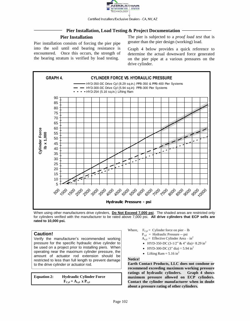
The pier is subjected to a proof load test that is
greater than the pier design (working) load.
Graph 4 below provides a quick reference to
determine the actual downward force generated
on the pier pipe at a various pressures on the
drive cylinder.
GRAPH 4. CYLINDER FORCE VS. HYDRAULIC PRESSURE
HYD-350-DC Drive Cyl (8.29 sq.in.) PPB-350 & PPB-400 Pier Systems
HYD-300-DC Drive Cyl (5.94 sq.in) PPB-300 Pier Systems
HYD-254 (5.16 sq.in.) Lif ting Ram
90
85
80
75
70
65
60
55
50
45
40
35
30
25
20
15
10
5
Hydraulic Pressure - psi
When using other manufacturers drive cylinders, Do Not Exceed 7,000 psi. The shaded areas are restricted only for cylinders verified with the manufacturer to be rated above 7,000 psi. All drive cylinders that ECP sells are rated to 10,000 psi.
Caution! Verify the manufacturer’s recommended working pressure for the specific hydraulic drive cylinder to be used on a project prior to installing piers. When operating near the maximum cylinder pressure, the amount of actuator rod extension should be restricted to less than full length to prevent damage to the drive cylinder or actuator rod.
Equation 2: Hydraulic Cylinder Force
FCyl = Acyl x Pcyl
Where, FCyl = Cylinder force on pier – lb
Pcyl = Hydraulic Pressure -- psi
Acyl = Effective Cylinder Area – in2
HYD-350-DC (3-1/2” & 4” dia)= 8.29 in2
HYD-300-DC (3” dia) = 5.94 in2
Lifting Ram = 5.16 in2
Notice!
Earth Contact Products, LLC does not condone or
recommend exceeding maximum working pressure
ratings of hydraulic cylinders. Graph 4 shows
maximum pressure allowed on ECP cylinders.
Contact the cylinder manufacturer when in doubt
about a pressure rating of other cylinders.

Page 103
EC
P S
tee
l P
ier™
De
sig
n
Proof Testing and Project Documentation
The big advantage when using hydraulically
installed ECP Steel Piers™
is that each pier is field Proof Tested to a load that is greater than force that is required to restore and support the structure. This Proof Testing of each and every pier placement verifies that firm bearing stratum or rock upon which the pier pipe is founded is sufficient to support the working load requirement plus a factor of safety.
It is recommended that the installer document the
following data for each pier placement:
1. The installation force used to drive each 3-
1/2 foot long section of pier pipe into the
soil.
2. The Proof Test force that was applied against the bearing stratum. This force shall
be either the force required to slightly lift
the structure using just the drive cylinder or
the application of the maximum allowable
test load shown in Table 1, whichever is
less.
3. The length of time the pier was subjected to
the Proof Test loading.
4. The depth to load bearing
5. After all pier placements have been
installed and Proof Tested, the force
required at each placement to recover lost
elevation to restore the structure shall be
recorded.
6. The amount of lift at each placement.
At the end of the project, this data shall be
compiled into a project report and retained by the
installer for future reference. The installer
should provide a copy of the project report to the
engineer of record or owner’s representative
upon request.
Buckling Loads on the Pier Shaft in Weak Soil
Whenever a slender column (Pier Pipe) does not have adequate lateral support from the surrounding soil, the load carrying capacity of the column is reduced as buckling of the pipe column becomes a risk. In the case of ECP Steel
Piers™
, the full ultimate-limit capacity shown in Table 1 is available provided the soil through which the pier penetrates maintains a Standard
assumed negligible and the pile is assumed
straight. Equation 3 is Davisson’s formula.
Equation 3: Critical Buckling
Pcr = Ucr Ep Ip / R2
Where:
Pcr = Critical Buckling Load – lb
Ucr = Dimensionless ratio (Assume = 1) Penetration Test value “N” > 5 blows per foot
through the entire depth of the pier installation. Ep = Shaft Mod. of Elasticity = 30 x 10
6 psi
4
The pier must also be firmly secured to a
foundation bracket at the footing.
The most accurate way to determine the buckling
load of a pier shaft in weak soil is by performing
a buckling analysis by finite differences. There
are several specialized computer programs that
can perform this analysis and allow the
introduction of shaft properties and soil
conditions that can vary with depth. Another,
less accurate method of estimating critical
buckling is by Davisson Method, “Estimating
Buckling Loads for Piles” (1963). In this
method, Davisson assumes various combinations
of pile head and tip boundary conditions with a
constant modulus of sub-grade reaction, “kH”.
Load transfer to the soil due to skin friction is
Ip = Shaft Moment of Inertia = in
R = 4√ Ep Ip / kH d
d = Shaft Diameter – in
Computer analysis of shaft buckling is the
recommended method to achieve the most
accurate results. Many times, however, one must
have general information to prepare a
preliminary design or budget proposal. Table
13, Page 106 below provides conservative
critical buckling load estimates for various shaft
sizes penetrating through different types of
homogeneous soils.
Graph 5 on the following page presents visual
representation of Buckling Strength of various
pier configurations when fully exposed in air, or
water, when no lateral shaft support is present.
It is recommended that a Registered Professional Engineer conduct the design of ECP Steel Piers™
where the pipe column is likely to be in weak soil and shaft buckling may occur.

Page 104
Table 12 STEEL PIER SHAFT STIFFNESS COMPARISON
Steel Pier Pipe Configuration
Cross Section
Area - in2
Moment of Inertia - in4
(Stiffness)
Pier Stiffness Relative to
PPB-350-EPS PPB-300-EPS (2-7/8” dia.) 1.41 1.29 0.55%
PPB-300-EPS + PPB-300-IP 2.65 1.81 0.77%
PPB-350-EPS (3-1/2” dia.) 1.68 2.35 100%
PPB-400-EPS (4” dia.) 2.60 4.66 198%
PPB-350-EPS + PPB-350-IP 3.46 4.22 180%
PPB-350-EPS + PPB-350-SB 4.27 7.01 298%
PPB-350-EPS + PPB-350-SB + PPB-350-IP
5.12
8.88
379%
Ma
xim
um
All
ow
ab
le L
oa
d -
lb
x 1
,00
0
Allowable Compressive Loads - “P” in Air: Graph 5 shows the
reduction in allowable axial
compressive loading where the pier
shaft has no lateral support.
Table 12 illustrates demonstrates
how the ECP PPB-400-EPS (4 inch
diameter) pier pipe provides an
axial stiffness of more than 3-1/2
times that of a PPB-300-EPS (2-7/8
inch diameter) pier pipe. In
addition, Graph 5 demonstrates that
the PPB-400-EPS pier pipe has a
maximum compressive load
capacity of more than three times
that of the PPB-300-EPS pier pipe
when each has ten feet of exposed
column height without any lateral
support.
Whenever weak soil is encountered
such as peat or other organic soils,
improperly consolidated soil, or a
situation where a portion of the pier
shaft may become fully exposed;
consideration MUST be given to the
reduction in capacity brought on by
the lack of lateral support to the pier
pipe.
In situations where insufficient
lateral pier pipe support is provided
by the soil, the pier is not able to
100
90
80
70
60
50
40
30
20
10
M aximum Allowable Compre ssiv e Load on
Ste e l Pie rs Without Soil Support
(P iers Mus t B e Grout Filled)
3-1/ 2"+ 4" SB + I. S.
3-1/ 2" + 4" SB
4"- 0. 237"
3-1/ 2" + IS
3-1/ 2"- 0. 165"
2-7/ 8"+ IS
2-7/ 8"- 0. 165"
0 4 6 8 10 12 14 16
Unsupporte d Colum n He ight - ft
support the full rated capacity. The
length of pier pipe that is passing
Graph 5. Maximum Load* on piers with NO soil support
through the weak soil and the amount of stiffness provided by the pier pipe will affect the load capacity reduction that must be considered. Pier pipe stiffness (Moment of Inertia) increases with increasing diameter. Graph 5 shows reductions in allowable axial compressive loading relative to the exposed length of the pier pipe in air or water for various pier diameters and sleeved pier configurations. When
ECP Steel Pier™
pipe is fully exposed or passes through very weak
soils, we recommend installing
sleeving over and/or inside the pier
pipe to increase the bending strength
of the pier; in addition, it is good
practice for the designer to consider
using a larger diameter pipe in weak
soil applications.
* Caution: When selecting a pier
configuration for a specific
application, one must apply a factor
of safety to the capacities shown on
Graph 5 to insure “Safe Use” design. EPS = Pier Pipe Section IP = Internal “Inertia” Sleeve SB = 4” External Sleeve

Page 105
EC
P S
tee
l P
ier™
De
sig
n
Pier Sleeves
In areas of poor soil, the stiffness (axial moment of inertia) of
the pier pipe and the strength of the coupled joints are of
concern. Installing a pier sleeve or changing to a larger
diameter pier pipe is required to prevent buckling. Poor soil
conditions are generally recognized as:
Soil having Standard Penetration Blow Counts less than or
equal to five blows per foot (“N” < 5) or,
On projects where the pier pipe is exposed, or may become
exposed
There are several ways to reinforce pier pipe in such situations.
One of the simplest to slightly improve pier stiffness and to
strengthen the coupled joints is to grout the pier pipe after
installation. Many designers also require that the contractor
install a reinforcing bar in the center of the pier pipe along with
the grouting to improve joint strength.
“Inertia Sleeve” – Earth Contact Products offers a patented
product called the Inertia Sleeve to improve shaft stiffness.
This unique product is shown in Figure 5, and is the most
economical way to quickly enhance the axial moment of inertia
(stiffness) of the pier system. The Inertia Sleeve is easy to
install, but must be installed concurrent with driving the pier
pipe. One simply allows an Inertia Sleeve section to drop by
gravity into the most recently installed section of pier pipe.
This must be done prior to coupling together and driving the
next section of pier pipe.
The low cost Inertia Sleeve takes nearly no labor to install and
PIER SECTION
INERTIA SLEEVE
PIER SECTION
COUPLING
INERTIA SLEEVE
COUPLING
PIER SECTION
TYPICAL
ASSEMBLY DETAIL
instantly increases the rigidity and strength of the pier shaft
through weak soil. The unique design of the patented “Inertia
Sleeve” also strengthens the coupled joints.
Figure 5. Details of ECP’s patented PPB-300-IP and PPB-350-IP Internal “Inertia Sleeve” Assembly
The coupling connection of the Inertia Sleeve
fully passes through the pier pipe coupling and
engages with the previously installed section of
Inertia Sleeve. The couplings are therefore
doubled and staggered, providing a strengthened
coupled joint.
External Sleeve – Another means of increasing
the axial moment of inertia of the pier shaft is to
install external pier sleeving. Many designers
like this method because it provides a
significantly larger increase in pier rigidity than
other methods. This is because the external
sleeve increases the diameter of the pier shaft.
When installed, each external sleeve must be
positioned such that the joints on the external
sleeving are staggered and are not near the pier
pipe couplings. The external sleeving must be
hydraulically driven over the installed pier pipe
prior to field load testing. The time required to
drive the external pier sleeving is generally
equivalent to the time required to initially install
the pier pipe. Keep in mind, however, that external sleeving is only required at locations where the pier pipe is exposed with no lateral
support or where the pier pipe passes through
weak soil with insufficient lateral support on the pipe shaft.
Table 12 on the previous page presents shaft
stiffness relative to different pier pipe
configurations. It is interesting to note that the
combination of the PPB-350-EPS, 3-1/2”
diameter pier pipe, plus the PPB-350-IP Inertia
Sleeve provides axial stiffness equal to 91% of the
of the PPB-400 system (4” diameter) system. If
the designer chooses PPB-350-SP (4” diameter
exterior sleeve) over the PPB-350-EPS (3-1/2
inch diameter) pier pipe and grout fills pier pipe,
the allowable load on the system will be 151%
that of a simple PPB-400 (4” diameter) pier
Page 106
system. The cost savings should be very evident
especially on projects that require extra rigidity
only in the upper several feet of soil.
When specifying either type of pipe sleeve, the
designer must extend the sleeving a minimum
depth of three feet beyond the zone of weak soil
and into the competent material.
For example, if a site has 6 feet of peat with
Standard Penetration Test (SPT), “N”, from 0 bpf
(“Weight of Hammer”) to 2 bpf that is overlaying
sand with a SPT, “N” > 5 blows per foot; the
designer should specify sleeving to a depth of at
least 9 feet in order to provide adequate sleeve
embedment beyond the 6 foot zone of weak soil
that contains peat.
“Quick and Rough” Buckling Load Estimates for Weak Soil Conditions
A method for instantly estimating Maximum
Conservative Working Loads in Weak Soil
can be found in Table 13 below. General soil
types and SPT, “N”, values are provided in four
columns. On the left side of Table 13 are
available pier pipe and sleeving configurations.
Read horizontally until the column with soil that
most closely matches the soil conditions at the
job site. At the intersection of the product line
and soil column is the maximum Design Load
(Working Load) for that pier or pier
combination. If the capacity is unsufficient, drop
down to a stiffer pier for the job.
Please note that the values given in Table 13
are working loads. A Factor of Safety of 2.0
has been applied to the loads in Table 13.
Table 13 Working Loads Under Buckling Conditions For Budgetary Estimating (Factor of Safety = 2)
Shaft Size
Uniform Soil Condition
Organics N < 1
Very Soft Clay N = 1 - 2
Soft Clay N = 2 - 4
Loose Sand N = 2 - 4
PPB-300-EPS (2-7/8” dia.) 19,000 lb 22,000 lb 31,000 lb 26,000 lb PPB-300-EPS + PPB-300-IP 23,000 lb 27,000 lb 39,000 lb 32,000 lb
PPB-350-EPS (3-1/2” dia.) 26,000 lb 30,000 lb 43,000 lb 35,000 lb
PPB-400-EPS (4” dia.) 34,000 lb 40,000 lb 57,000 lb 46,000 lb
PPB-350-EPS + PPB-350-IP 36,000 lb 42,000 lb 59,000 lb 48,000 lb
PPB-350-EPS + PPB-350-SB 50,000 lb 58,000 lb 82,000 lb 67,000 lb
PPB-350-EPS + PPB-350-SB + PPB-350-IP 56,000 lb 66,000 lb 93,000 lb 76,000 lb
EPS = Pier Pipe Section IP = Internal “Inertia” Sleeve SB = 4” Ext Sleeve
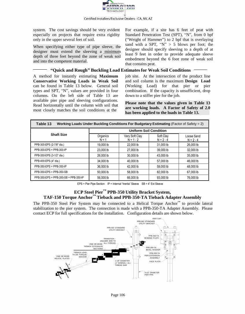
ECP Steel Pier™
PPB-350 Utility Bracket System,
TAF-150 Torque Anchor™
Tieback and PPB-350-TA Tieback Adapter Assembly
The PPB-350 Steel Pier System may be connected to a Helical Torque Anchor™
to provide lateral
stabilization to the pier system. The connection is made with a PPB-350-TA Adapter Assembly. Please
contact ECP for full specifications for the installation. Configuration details are shown below. PIER CAP
PPB-350 STANDARD
UTILITY BRACKET
PPB-350 STANDARD
UTILITY BRACKET
ONE OR MORE
HELICAL PLATES
TRANSITION -
(SQUARE BAR TO
ONE OR MORE ALL-THREAD)
TIEBACK EXTENSION
SECTIONS
TIEBACK LEAD
TA-150 TORQUE
ANCHOR
1-1/8" DIAMETER
(1" NOMINAL) ALL-
THREAD BAR
PPB-350-TA
BEARING PLATE
PPB-350-TA
BEVEL WASHER
PPB-350-TA
PIER EXTENSION
ASSEMBLY
FACE PLATE
3-1/2" DIAMETER
PIER PIPE