steel truss load assessment using fea to as 5100 plus
TRANSCRIPT

Steel Truss Load Assessment using FEA to
AS 5100
Plus (bonus) – Sensors and FLA

Steel Truss Load Assessment for Aging Bridges using FEA and AS5100:2017
The Want
The Method
Old style
AS 5100 2017
Validation
The Result
Limitations
2
Outline

Steel Truss Load Assessment for Aging Bridges using FEA and AS5100:2017
QR operate/maintain a series of steel truss bridges over major
water crossings from Brisbane to Cairns – North Coast Line
(NCL)
The bridges vary in age, from circa 1880’s to 1960’s
Load rating and remnant life assessment required
Traditional methods too conservative or limited
As-is condition
3
The Want

Steel Truss Load Assessment for Aging Bridges using FEA and AS5100:2017
Disclaimer – I was part of the project team, but I did not drive
ANSYS. If you have technical questions about the use of the
software, I will take that on notice and refer to my colleagues.
Example for 80 foot truss
Some may recognise the truss from David’s presentation – part
of a multi-faceted project (sub-structure, bearing replacement,
remediation etc).
4
The Want

Steel Truss Load Assessment for Aging Bridges using FEA and AS5100:20175
The Want

Steel Truss Load Assessment for Aging Bridges using FEA and AS5100:2017
Rockfield scope
Create full 3D solid models and FE models of 3 unique truss
spans
Analyse and load rate to AS5100.6
Allow for significant corrosion
Instrument with strain gauges and measure for a few months
Calculate remnant life
6
The Want
Steel Truss Load Assessment for Aging Bridges using FEA and AS5100:2017
Beam element model
Solid model
Finite element model
Finite element analysis
Sensors
Fatigue and remnant life
7
The Method

Steel Truss Load Assessment for Aging Bridges using FEA and AS5100:2017
Beam element model
Faster, moving load etc
Familiar
Sanity check
Lower bound capacity estimate
Limitations – joint stiffness, corrosion
Connection design
8
The Method
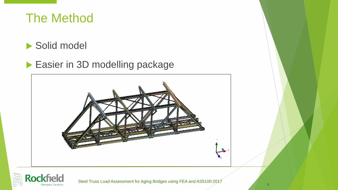
Steel Truss Load Assessment for Aging Bridges using FEA and AS5100:2017
Solid model
Easier in 3D modelling package
9
The Method

Steel Truss Load Assessment for Aging Bridges using FEA and AS5100:2017
Finite element model
ANSYS
Solid-Shell elements
Fully bonded
connections U.N.O
Beam elements for
simple members
10
The Method
Solid element Shell + beam element

Steel Truss Load Assessment for Aging Bridges using FEA and AS5100:2017
Old style
Modify Young’s
Modulus
Compare beam
capacity FEA vs
hand calc
Adjust stress-strain
curve to suit
11
The Method

AS5100 vs ANSYS results
12
Old style
Capabilities and Project Examples
ANSYS non-linear
buckling analysis
AS5100
Compression test
(Max. compression
force)
738kN 739kN
Moment test (Max
load)
6.8 kN/m 6 kN/m
Force
310UB46, 4m , simply supported, solid element
310UB46, 8m, simply
supported, shell element
UDL
Last converged load=738kN
φNc=739kN (AS4100)

Steel Truss Load Assessment for Aging Bridges using FEA and AS5100:2017
Analysis to AS 5100.6 2017
13
The Method

Steel Truss Load Assessment for Aging Bridges using FEA and AS5100:2017
Modified Stress-strain curve
Soften E a little bit
Factored yield
14
The Method
207
184
225
0
50
100
150
200
250
0 0.001 0.002 0.003 0.004 0.005 0.006
Str
ess [M
Pa]
Strain [με]
Stress-Strain Curves for steel
Original Steel Rivet New Bracing System

Steel Truss Load Assessment for Aging Bridges using FEA and AS5100:2017
Real beams = imperfections
Local = plate buckling e.g. Ms, Ns, V
Global = member buckling e.g. Mb, Nc
15
The Method

Steel Truss Load Assessment for Aging Bridges using FEA and AS5100:2017
Local Imperfections
Linear eigenvalue buckling of critical load cases
Save the mode shape data
Scale the shapes to real displacements
Input to the model – move the nodes to match the scaled shape
Zero stress
16
The Method

Steel Truss Load Assessment for Aging Bridges using FEA and AS5100:2017
Global Imperfection
Push member sideways with a unit UDL to yield lateral
displacement. Restrain all other members.
Scale the displacement
Input to the model – move the nodes to match the scaled
shape
Zero stress
17
The Method
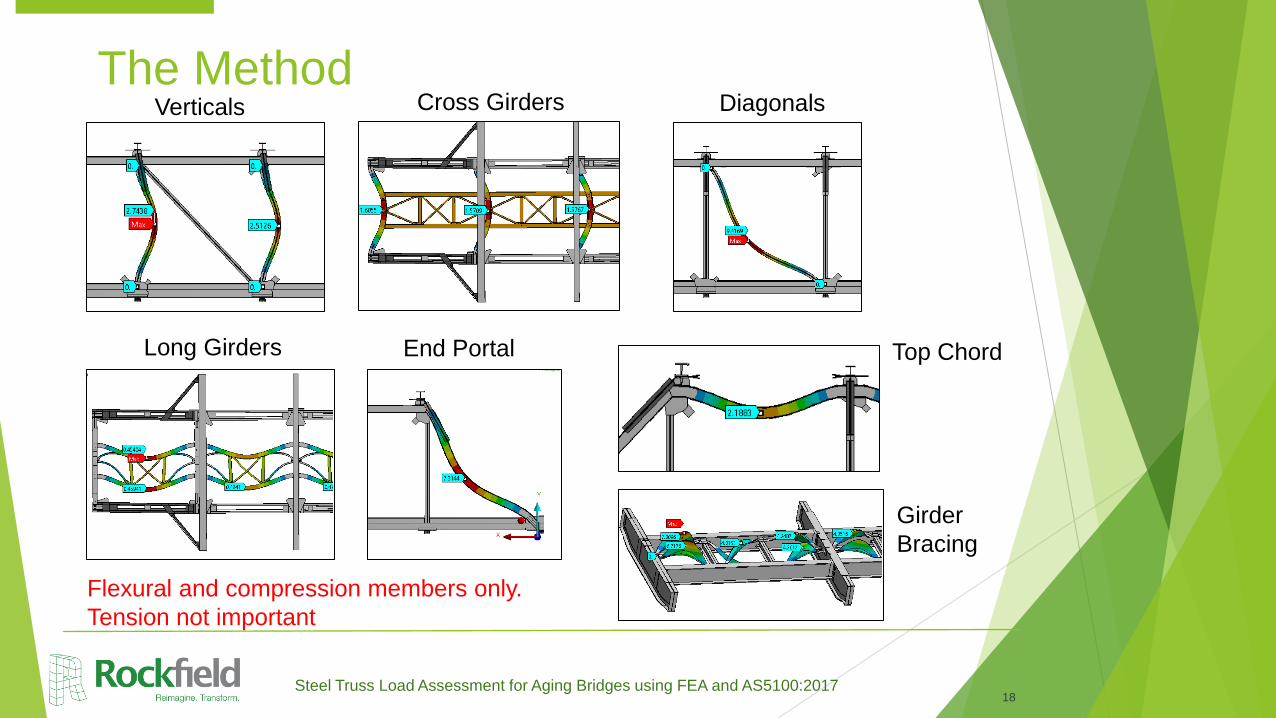
Steel Truss Load Assessment for Aging Bridges using FEA and AS5100:201718
The MethodVerticals Cross Girders Diagonals
Long Girders End Portal Top Chord
Girder
Bracing
Flexural and compression members only.
Tension not important
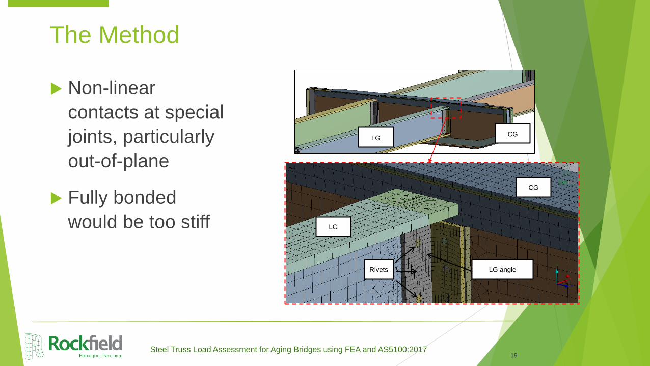
Steel Truss Load Assessment for Aging Bridges using FEA and AS5100:2017
Non-linear
contacts at special
joints, particularly
out-of-plane
Fully bonded
would be too stiff
19
The Method
Rivets
LG
CG
CGLG
LG angle

Steel Truss Load Assessment for Aging Bridges using FEA and AS5100:2017
Non-linear
contacts at special
joints, particularly
out-of-plane
20
The Method

Steel Truss Load Assessment for Aging Bridges using FEA and AS5100:2017
Corrosion
Scan thickness
survey data and
decide what is
significant
Simplify thickness
loss for modelling
21
The Method
Steel Truss Load Assessment for Aging Bridges using FEA and AS5100:2017
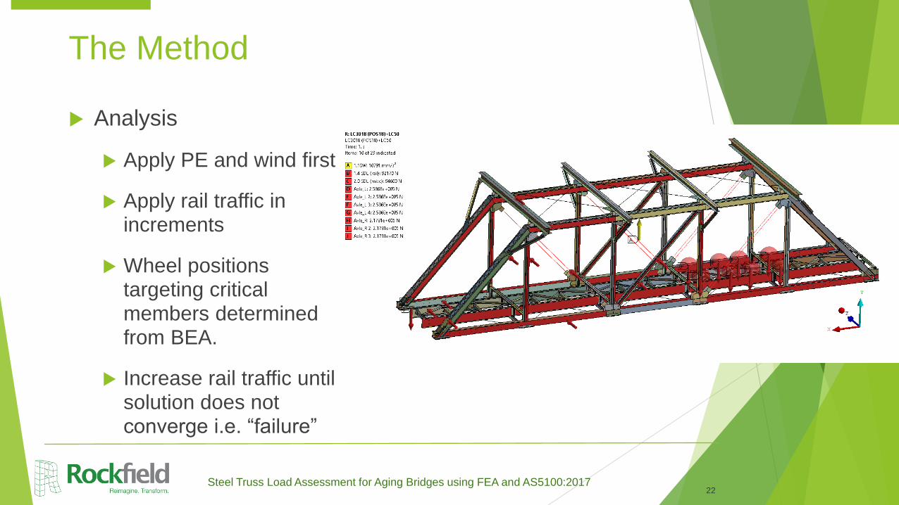
Analysis
Apply PE and wind first
Apply rail traffic in increments
Wheel positions targeting critical members determined from BEA.
Increase rail traffic until solution does not converge i.e. “failure”
22
The Method
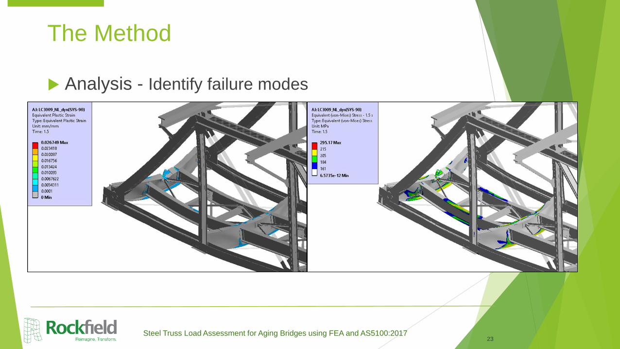
Steel Truss Load Assessment for Aging Bridges using FEA and AS5100:2017
Analysis - Identify failure modes
23
The Method

Steel Truss Load Assessment for Aging Bridges using FEA and AS5100:2017
Analysis - Calculate capacity, allowing for DLA and LL factors
If X is positive (X>0), then (1+X)>1.0, and truss has sufficient capacity for 200A loading.
Similar, but not identical to, Load Rating Factor (RF), or Equivalent Ratio Traffic ERT
24
The Method
200𝐴(+) = 𝐺 +𝑊 + 𝑄200𝐴 1 + 𝑋
൯200𝐴(+) = 𝛾𝑔𝑆𝑊 + 𝛾𝑔𝑠𝑆𝐷𝐿 + 𝛾𝑔𝑏𝑇𝐿 +𝑊 + 𝛾𝑄 𝑎𝑥𝑙𝑒200𝐴 1 + 𝛼 + 𝐵𝐹 + 𝑁𝐹 (1 + 𝑋
𝑄 )200𝐴(+ = 𝑄200𝐴 1 + 𝑋

Steel Truss Load Assessment for Aging Bridges using FEA and AS5100:2017
Validation
Strain gauges
Load test
Longer term for Fatigue Life
25
The Method

Steel Truss Load Assessment for Aging Bridges using FEA and AS5100:2017
Compare
measurements
against model
26
The Method
Good shape correlation
FEA magnitudes a little
higher (conservative)
Steel Truss Load Assessment for Aging Bridges using FEA and AS5100:2017
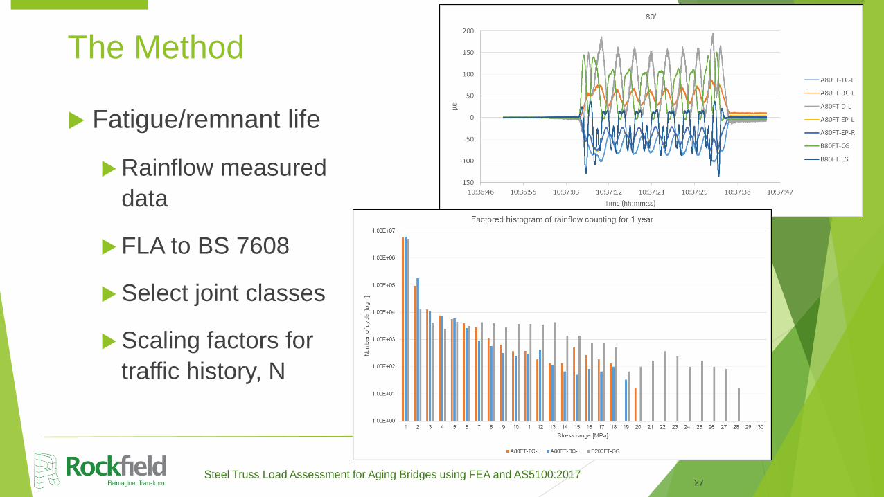
Fatigue/remnant life
Rainflow measured
data
FLA to BS 7608
Select joint classes
Scaling factors for
traffic history, N
27
The Method

Steel Truss Load Assessment for Aging Bridges using FEA and AS5100:2017
Fatigue/remnant life
Model moving load
Critical location not the same as measurement location
Scaling factors for stress, s
Calculate fatigue damage fraction to date
Calculate remaining time to reach damage fraction = 1.0 i.e. remnant life
28
The Method
Steel Truss Load Assessment for Aging Bridges using FEA and AS5100:2017
Improved capacity compared to traditional calculations
BEA – limiting capacity = 0.71 end cross girder (AS-NEW)
FEA – truss capacity = 0.77 (AS-IS)
Better modelling of corrosion affected areas
Good correlation with sensor data
Remnant life assessment based on real usage
29
The Result

Steel Truss Load Assessment for Aging Bridges using FEA and AS5100:2017
In-plane shear connections – too much time and complexity, hand calcs good enough
Time
Modelling
Debugging
Solving
Select load cases
Whole truss rating, not per member
30
Limitations

Thank you.