steel_ch6 - connections2
TRANSCRIPT

8/19/2019 Steel_Ch6 - Connections2
http://slidepdf.com/reader/full/steelch6-connections2 1/128
68402/61420 Slide # 1
68402: Structural Design ofBuildings II
Design of Connections
Monther DwaikatAssistant rofessor
De!art"ent of Building #ngineeringAn$%a&ah %ational 'ni(ersit)

8/19/2019 Steel_Ch6 - Connections2
http://slidepdf.com/reader/full/steelch6-connections2 2/128
68402/61420 Slide # 2
Types of ConnectionsSimple Bolted Shear ConnectionsBearing and Slip Critical ConnectionsEccentric Bolted Connections
oment !esisting Bolted ConnectionsSimple "elded Connections
Eccentric "elded Connectionsoment !esisting "elded Connections
Bolted Connections

8/19/2019 Steel_Ch6 - Connections2
http://slidepdf.com/reader/full/steelch6-connections2 3/128
68402/61420 Slide #
*)!es of ConnectionsSimple Connections
Bolted Connections Welded Connections
Common Bolts High Strength Bolts
Slip Critical
Bearing Type
Filet Weld
Groove Weld
Eccentric Connections

8/19/2019 Steel_Ch6 - Connections2
http://slidepdf.com/reader/full/steelch6-connections2 4/128
68402/61420 Slide # 4
*)!es of Connections
Simple Connections
Bolted Connections Welded Connections
ElasticAnalysis
Eccentric Connections
UltimateAnalysis
MomentResisting
ElasticAnalysis
UltimateAnalysis
MomentResisting

8/19/2019 Steel_Ch6 - Connections2
http://slidepdf.com/reader/full/steelch6-connections2 5/128

8/19/2019 Steel_Ch6 - Connections2
http://slidepdf.com/reader/full/steelch6-connections2 6/128
68402/61420 Slide # 6
Si"!le Bolted Connections
Tension mem%er
Connection/ splice
Beam end
Simple shear connection
.
.
.
.

8/19/2019 Steel_Ch6 - Connections2
http://slidepdf.com/reader/full/steelch6-connections2 7/128
68402/61420 Slide #
Si"!le Bolted Connections
. .
.
-anger connection
Tension
oment resisting
connection

8/19/2019 Steel_Ch6 - Connections2
http://slidepdf.com/reader/full/steelch6-connections2 8/128
68402/61420 Slide # 8
Si"!le Bolted ConnectionsThe %olts are s*%+ected to shear or tension loading&
( )n most %olted connection the %olts are s*%+ected to shear&
( Bolts can fail in shear or in tension&
( 3o* can calc*late the shear strength or the tensile strength of a %olt
Simple connection )f the line of action of the force acting onthe connection passes thro*gh the center of gra5ity of theconnection then each %olt can %e ass*med to resist an e *al
share of the load&The strength of the simple connection 7ill %e e *al to thes*m of the strengths of the indi5id*al %olts in the connection&

8/19/2019 Steel_Ch6 - Connections2
http://slidepdf.com/reader/full/steelch6-connections2 9/128
68402/61420 Slide #
Bolt *)!es + Materials 9 0 : Unfinished Ordinary or Common %olts
lo7 car%on steel 9 6 F u ; 41 .afor light str*ct*res *nder static load
9 2$ : High strength %olts heat:treated medi*mcar%on steel F u ; 82 .a
for str*ct*ral +oints 94 0 : High strength %olts <*enched and
Tempered 9lloy steel F u ; 10 .a
for str*ct*ral +oints 944 : High strength %olts 7ith diameter = 1 >?
anchor %olts lifting hoo,s tie:do7ns

8/19/2019 Steel_Ch6 - Connections2
http://slidepdf.com/reader/full/steelch6-connections2 10/128
68402/61420 Slide # 10
Co""on Bolts 9ST 9 0 %oltsCommon %olts are no longer common for c*rrent str*ct*raldesign %*t are still a5aila%le
bolt vn A f R =
75.0=φ nu R P φ ≤
MPa f v
165=

8/19/2019 Steel_Ch6 - Connections2
http://slidepdf.com/reader/full/steelch6-connections2 11/128
68402/61420 Slide # 11
,igh Strength Bolts-igh strength %olts -SB are a5aila%leas 9ST 9 2$ and 9ST 94 0
Slip Critical
Bearing Type
Courtesy of Kao Wang Screw Co., Ltd.
Advantages o HSB over A!"# $olts
Fe%er $olts %ill $e &sed compared to !"# cheaper connection'
Smaller %or(man orce re)&ired compared to !"#
Higher atig&e strength
Ease o $olt removal changing connection
Bolt
Washer
Nut

8/19/2019 Steel_Ch6 - Connections2
http://slidepdf.com/reader/full/steelch6-connections2 12/128
68402/61420 Slide # 12
,igh Strength BoltsSnug tight( 9ll plies of the connection are in firm contact to
each other @o pretension is *sed&( Easer to install and to inspect
Pre-tensioned
( Bolts are first %ro*ght to sn*g tight stat*s( Bolts are then tensioned to 0A of their tensilestresses
Courtesy of www.halfpricesurplus.com
( Bolts are tensioned *sing direct tension indicator cali%rated 7rench or othermethods see 9)SC
Slip critical( Bolts are pre:tensioned %*t s*rfaces shall %e treated to de5elop specific friction&
( The main difference is in design not installation& oad m*st %e limited not toe ceed friction capacity of the connection Strength Ds& Ser5icea%ility
( @ecessary 7hen no slip is needed to pre5ent fail*re d*e to fatig*e in %ridges&

8/19/2019 Steel_Ch6 - Connections2
http://slidepdf.com/reader/full/steelch6-connections2 13/128
68402/61420 Slide # 1
,SB - Bearing *)!e ConnectionsThe shear strength of %olts shall %e determined as follo7s
bolt vn A f R =
75.0=φ nu R P φ ≤
*+#,+!A,-"
,+!!!"A!.*
Type / ThreadType 0 ThreadType
( )f the le5el of threads is not ,no7n it is conser5ati5e toass*me that the threads are type @&
AISC Table !."
The table bellow shows the values of f v (MPa) for different types of bolts

8/19/2019 Steel_Ch6 - Connections2
http://slidepdf.com/reader/full/steelch6-connections2 14/128
68402/61420 Slide # 14
Bolted Shear Connections "e 7ant to design the %olted shear connections so thatthe factored design strength φ! n is greater than or e *alto the factored load& φ ! n ≥ . *
So 7e need to e amine the 5ario*s possi%le fail*remodes and calc*late the corresponding design strengths&
.ossi%le fail*re modes are( Shear fail*re of the %olts
( Fail*re of mem%er %eing connected d*e to fract*re or yielding or G&( Edge tearing or fract*re of the connected plate
( Tearing or fract*re of the connected plate %et7een t7o %olt holes
( E cessi5e %earing deformation at the %olt hole

8/19/2019 Steel_Ch6 - Connections2
http://slidepdf.com/reader/full/steelch6-connections2 15/128
68402/61420 Slide # 1$
.ailure Modes of BoltedConnections
Bolt Shearing
Tension Fract*re
.late Bearing
Bloc, Shear

8/19/2019 Steel_Ch6 - Connections2
http://slidepdf.com/reader/full/steelch6-connections2 16/128
68402/61420 Slide # 16
Actions on Bolt
Shear %earing %ending
P P
P
P
P P
P/2 P
P/2
P/2
P/2 P
Lap oint
#utt oint
Bearing and single plane Shear
Bending
Bearing and double plane Shear

8/19/2019 Steel_Ch6 - Connections2
http://slidepdf.com/reader/full/steelch6-connections2 17/128
68402/61420 Slide # 1
Bolted Shear Connections1ossi$le ail&re modes
Fail&re o $olts2 single or do&$le shear
Fail&re o connected elements2
Shear3 tension or $ending ail&re of the connected elements ( e4g4 $loc( shear )Bearing ail&re at bolt location
Single shear
5o&$le shear
bolt vShear Single A f P =
bolt vShear Double A f P 2= P
P P
2/ P
2/ P
8/19/2019 Steel_Ch6 - Connections2
http://slidepdf.com/reader/full/steelch6-connections2 18/128
68402/61420 Slide # 18
Bolted Shear Connections
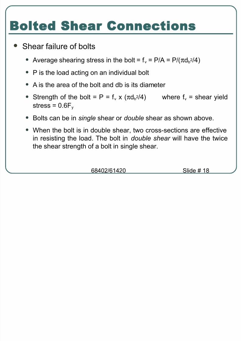
Shear fail*re of %olts
( 95erage shearing stress in the %olt ; f 5 ; ./9 ; ./ πd%2/4
( . is the load acting on an indi5id*al %olt
( 9 is the area of the %olt and d% is its diameter
( Strength of the %olt ; . ; f 5 πd%2/4 7here f 5 ; shear yieldstress ; 0&6F y
( Bolts can %e in single shear or double shear as sho7n a%o5e&
( "hen the %olt is in do*%le shear t7o cross:sections are effecti5ein resisting the load& The %olt in double shear 7ill ha5e the t7icethe shear strength of a %olt in single shear&

8/19/2019 Steel_Ch6 - Connections2
http://slidepdf.com/reader/full/steelch6-connections2 19/128
68402/61420 Slide # 1
Bolted Shear Connections

8/19/2019 Steel_Ch6 - Connections2
http://slidepdf.com/reader/full/steelch6-connections2 20/128
68402/61420 Slide # 20
Bolted Shear ConnectionsFail*re of connected mem%er ( "e ha5e co5ered this in detail in this co*rse on tension mem%ers
( em%er can fail d*e to tension fract*re or yielding&
Bearing fail*re of connected/connecting part d*e to%earing from %olt holes
( -ole is slightly larger than the fastener and the fastener is looselyplaced in hole
( Contact %et7een the fastener and the connected part o5erappro imately half the circ*mference of the fastener
( 9s s*ch the stress 7ill %e highest at the radial contact point 9 &-o7e5er the a5erage stress can %e calc*lated as the applied forcedi5ided %y the pro+ected area of contact

8/19/2019 Steel_Ch6 - Connections2
http://slidepdf.com/reader/full/steelch6-connections2 21/128
68402/61420 Slide # 21
Bolted Shear Connections
( 95erage %earing stress f p ; ./ d % t 7here . is the force applied tothe fastener&
( The %earing stress state can %e complicated %y the presence ofnear%y %olt or edge& The %olt spacing and edge distance 7ill ha5e
an effect on the %earing strength&( Bearing stress effects are independent of the %olt type %eca*se
the %earing stress acts on the connected plate not the %olt&
( 9 possi%le fail*re mode res*lting from e cessi5e %earing close tothe edge of the connected element is shear tear:o*t as sho7n%elo7& This type of shear tear:o*t can also occ*r %et7een t7oholes in the direction of the %earing load&
R n = 2 !"# $ u %c t = &"2 $ u %c t

8/19/2019 Steel_Ch6 - Connections2
http://slidepdf.com/reader/full/steelch6-connections2 22/128
68402/61420 Slide # 22
The $earing strength is independent o the $olt material as it is ail&re inthe connected metal
The other possi$le common ail&re is shear end ail&re (no%n as 6 sheartear$out 7 at the connection end
t d f P bolt p Bearing =
Bolted Shear Connections
uucn F t d F t L R !.22.1 ≤=75.0=φ nu R P φ ≤
Shear limitation Bearing limitation
c Lc L

8/19/2019 Steel_Ch6 - Connections2
http://slidepdf.com/reader/full/steelch6-connections2 23/128
68402/61420 Slide # 2
Bolted Shear Connections

8/19/2019 Steel_Ch6 - Connections2
http://slidepdf.com/reader/full/steelch6-connections2 24/128
68402/61420 Slide # 24
Bolted Shear Connections

8/19/2019 Steel_Ch6 - Connections2
http://slidepdf.com/reader/full/steelch6-connections2 25/128
68402/61420 Slide # 2$
S!acing and #dge$distancere/uire"ents
The 9)SC code gi5es g*idance for edge distance and spacing toa5oid tear o*t shear
2h
L L ec −=
S e Ldia eter holetheish d h bolt 6.1+=
08TE2 "he actual hole diameter is 1.6 mm bigger than the bolt#
$e use another 1.6 mm for tolerance $hen $e calculate net area. %ere use +49 mm onl& not !4.
bolt d S '22≥
Bolt spacing is a &nction o the $olt diameterCommon %e ass&me
The A:SC minim&m spacing is
e L
bolt d S '=
AISC Table !.%

8/19/2019 Steel_Ch6 - Connections2
http://slidepdf.com/reader/full/steelch6-connections2 26/128
68402/61420 Slide # 26
Bolt S!acings + #dge Distances
Bolt Spacings: .ainted mem%ers or mem%ers not s*%+ect to corrosion
2 2/ d H Bolt Spacings ≤ 24 t or 0$ mm !FI J & !FI J &$
: Knpainted mem%ers s*%+ect to corrosion d H Bolt Spacings ≤ 14 t or 1 8 mm
Edge DistanceDal*es in Ta%le J &4 ≤ Edge Distance ≤ 12 t or 1$2 mm
!FI J &4 !FI J &$
d - bolt diametert - thickness of thinner plate
8/19/2019 Steel_Ch6 - Connections2
http://slidepdf.com/reader/full/steelch6-connections2 27/128
68402/61420 Slide # 2
Bolted Shear Connections
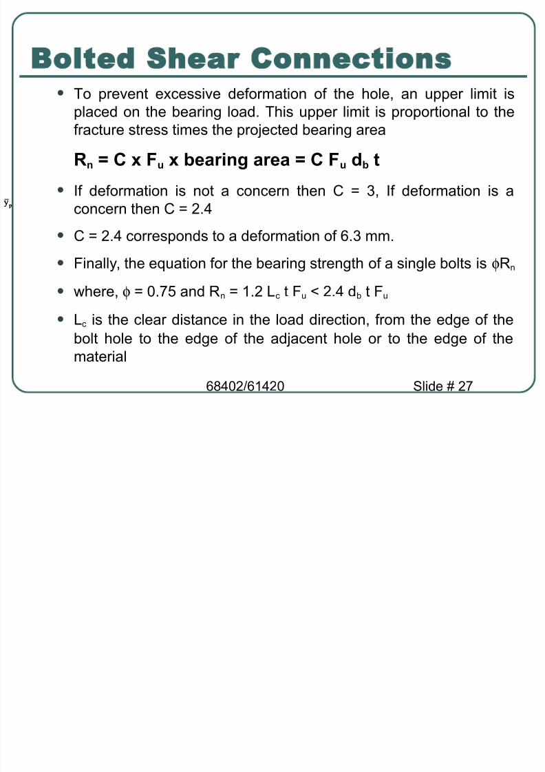
( To pre5ent e cessi5e deformation of the hole an *pper limit isplaced on the %earing load& This *pper limit is proportional to thefract*re stress times the pro+ected %earing area
R n = ' $ u bearing area = ' $ u d b t
( )f deformation is not a concern then C ; )f deformation is aconcern then C ; 2&4
( C ; 2&4 corresponds to a deformation of 6& mm&
( Finally the e *ation for the %earing strength of a single %olts is φ! n
( 7here φ ; 0& $ and ! n ; 1&2 c t F * L 2&4 d% t F *
( c is the clear distance in the load direction from the edge of the%olt hole to the edge of the ad+acent hole or to the edge of thematerial
p& p& p&

8/19/2019 Steel_Ch6 - Connections2
http://slidepdf.com/reader/full/steelch6-connections2 28/128
68402/61420 Slide # 28
Bolted Shear Connections
( This relationship can %e simplified as follo7sThe *pper limit 7ill %ecome effecti5e 7hen 1&2 c t F * = 2&4 d% t F *
i&e& the *pper limit 7ill %ecome effecti5e 7hen c = 2 d %
)f c L 2 d % ! n ; 1&2 c t F *
)f c = 2 d % ! n ; 2&4 d % t F *
F u - specified tensile strength of the connected material
Lc - clear distance, in the direction of the force, between the edge ofthe hole and the edge of the adjacent hole or edge of the material.
t - thickness of connected material

8/19/2019 Steel_Ch6 - Connections2
http://slidepdf.com/reader/full/steelch6-connections2 29/128
68402/61420 Slide # 2
I"!ortant %otes
c M Clear distance

8/19/2019 Steel_Ch6 - Connections2
http://slidepdf.com/reader/full/steelch6-connections2 30/128
68402/61420 Slide # 0
Design ro(isions for BoltedShear Connections
)n a simple connection all %olts share the load e *ally&
! !
!/n !/n
!/n !/n
!/n !/n
! !
!/n !/n
!/n !/n
!/n !/n

8/19/2019 Steel_Ch6 - Connections2
http://slidepdf.com/reader/full/steelch6-connections2 31/128
68402/61420 Slide # 1
Design ro(isions for BoltedShear Connections
)n a %olted shear connection the bolts are subjected toshear and the connecting/connected plates are s*%+ectedto %earing stresses&
Bolt in shear
Bearing stresses in plate
Bearing stresses in plate
! !
!
!
Bolt in shear
Bearing stresses in plate
Bearing stresses in plate
Bolt in shear
Bearing stresses in plate
Bearing stresses in plate
! !
!
!

8/19/2019 Steel_Ch6 - Connections2
http://slidepdf.com/reader/full/steelch6-connections2 32/128
68402/61420 Slide # 2
Design ro(isions for BoltedShear Connections
The shear strength of all %olts ; shear strength of one %olt n*m%er of %olts
The %earing strength of the connecting / connected platescan %e calc*lated *sing e *ations gi5en %y 9)SCspecifications&
The tension strength of the connecting / connected platescan %e calc*lated as disc*ssed in tension mem%ers&

8/19/2019 Steel_Ch6 - Connections2
http://slidepdf.com/reader/full/steelch6-connections2 33/128
68402/61420 Slide #
AISC Design ro(isions
Chapter J of the 9)SC Specifications foc*ses onconnections&
Section J foc*ses on %olts and threaded parts
9)SC Specification J & indicates that the minim*mdistance s %et7een the centers of %olt holes is 2&6 & 9distance of d % is preferred&
9)SC Specification J &4 indicates that the minim*m edge
distance e from the center of the %olt to the edge of theconnected part is gi5en in Ta%le J &4&Ta%le J &4 specifiesminim*m edge distances for sheared edges edges ofrolled shapes and gas c*t edges&
8/19/2019 Steel_Ch6 - Connections2
http://slidepdf.com/reader/full/steelch6-connections2 34/128
68402/61420 Slide # 4
AISC Design ro(isions
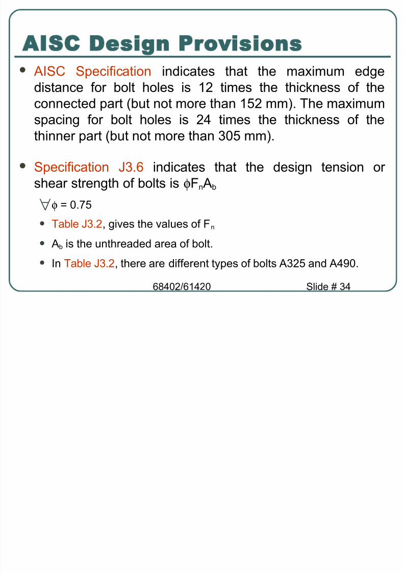
9)SC Specification indicates that the ma im*m edgedistance for %olt holes is 12 times the thic,ness of theconnected part %*t not more than 1$2 mm & The ma im*mspacing for %olt holes is 24 times the thic,ness of thethinner part %*t not more than 0$ mm &
Specification J &6 indicates that the design tension orshear strength of %olts is φF n 9 %
∀φ ; 0& $
( Ta%le J &2 gi5es the 5al*es of F n
( 9 % is the *nthreaded area of %olt&
( )n Ta%le J &2 there are different types of %olts 9 2$ and 94 0&

8/19/2019 Steel_Ch6 - Connections2
http://slidepdf.com/reader/full/steelch6-connections2 35/128
68402/61420 Slide # $
AISC Design ro(isions
( The shear strength of the %olts depends on 7hether threads areincl*ded or e cl*ded from the shear planes& )f threads are incl*dedin the shear planes then the strength is lo7er&
"e 7ill al7ays ass*me that threads are incl*ded in the
shear plane therefore less strength to %e conser5ati5e&
"e 7ill loo, at specifications J & M J & later&
( 9)SC Specification J &10 indicates the %earing strength of plates at
%olt holes&( The design %earing strength at %olt holes is φ! n
( ! n ; 1&2 c t F * H 2&4 d% t F * : deformation at the %olt holes is adesign consideration

8/19/2019 Steel_Ch6 - Connections2
http://slidepdf.com/reader/full/steelch6-connections2 36/128
68402/61420 Slide # 6
Co""on olt ter"inologies
9 2$:SC M slip!critical 9 2$ %olts 9 2$:@ M snug!tight or bearing 9 2$ %olts 7ith
thread included in the shear planes& 9 2$:N : snug!tight or bearing 9 2$ %olts 7ith
thread e"cluded in the shear planes&
#age $ center:to:center distance of %olts indirection perpendic*lar to
mem%erOs a is%itch $ &&¶llel to mem%erOs a isEdge Distance $ Iistance fromcenter of %olt to ad+acentedge of a mem%er
p
g
p p
p #dgedistance

8/19/2019 Steel_Ch6 - Connections2
http://slidepdf.com/reader/full/steelch6-connections2 37/128
68402/61420 Slide #
#1 3 $ Design Strength
Calc*late and chec, the design strength of the simpleconnection sho7n %elo7& )s the connection ade *ate forcarrying the factored load of 00 ,@&
1.25 2.50 1.25
1.25
2.50
1.25 65
'6
'6 5 * +
'/, in.
- in. bolts
1.25 2.50 1.25
1.25
2.50
1.25 65
'6
'6 5 * +
'/, in.
- in. bolts
6 ,
10 mm
120 1$ mm
20 mm 9 2$:@%olts
0 mm
60 mm
0 mm
0 mm 60 mm 0 mm
00 ,@

8/19/2019 Steel_Ch6 - Connections2
http://slidepdf.com/reader/full/steelch6-connections2 38/128
68402/61420 Slide # 8
Step " Shear strength of %olts( The design shear strength of one %olt in shear ; φF n 9 % ; 0& $
0 π 20 2/4000 ; &8 ,@
∀φ F n 9 % ; &8 ,@ per %olt See Ta%le J &2
( Shear strength of connection ; 4 &8 ; 11&2 ,@
#1 3 $ Design Strength

8/19/2019 Steel_Ch6 - Connections2
http://slidepdf.com/reader/full/steelch6-connections2 39/128
68402/61420 Slide #
Step " inim*m edge distance and spacing re *irements( See Ta%le J &4 minim*m edge distance ; 26 mm for rolled edges
of plates
( The gi5en edge distances 0 mm = 26 mm& Therefore minim*m edge
distance re *irements are satisfied&
( inim*m spacing ; 2&6 d % ; 2&6 20 ; $ &4 mm&
( S' Specifications *+"+)
( .referred spacing ; &0 d % ; &0 20 ; 60 mm&
( The gi5en spacing 60 mm ; 60 mm& Therefore spacing re *irementsare satisfied&
#1 3 $ Design Strength

8/19/2019 Steel_Ch6 - Connections2
http://slidepdf.com/reader/full/steelch6-connections2 40/128
68402/61420 Slide # 40
#1 3 $ Design Strength
Step "Bearing strength at %olt holes &( Bearing strength at %olt holes in connected part 120 1$ mm plate
( 9t edges c ; 0 M hole diameter/2 ; 0 M 20 P 1&6 /2 ; 1 &2
∀φ! n ; 0& $ 1&2 c t F * ; 0& $ 1&2 1 &2 1$ 400 /1000 ; 10 & ,@
( B*t φ! n H 0& $ 2&4 d% t F * ; 0& $ 2&4 20 1$ 400 /1000 ; 216 ,@
( Therefore φ! n ; 10 & ,@ at edge holes &
( 't other holes( s ) *+ mm ( c ) *+ $ ,-+ . /&*0 ) 12&3 mm&
∀φ! n ) +&45 " ,/&- c t F u 0 ) +&45",/&- " 12&3 "/5 "3++06/+++ ) -+4&3 78
( But( φ! n ≤ +&45 ,-&3 d b t F u 0 ) -/* 78& 9herefore φ! n ) -+4&3 78

8/19/2019 Steel_Ch6 - Connections2
http://slidepdf.com/reader/full/steelch6-connections2 41/128
68402/61420 Slide # 41
#1 3 $ Design Strength
( Therefore φ! n ; 216 ,@ at other holes( Therefore %earing strength at holes ; 2 10 & P 2 20 &4 ; 622&2 ,@
( Bearing strength at %olt holes in g*sset plate 10 mm plate
( 9t edges c ; 0 M hole diameter/2 ; 0 M 20 P 1&6 /2 ; 1 &2 mm&
∀φ! n ; 0& $ 1&2 c t F * ; 0& $ 1&2 1 &2 10 400 /1000 ; 6 &1,@
( B*t φ! n H 0& $ 2&4 d% t F * ; 0& $ 2&4 20 10 400 /1000 ; 144,@&
( Therefore φ! n ; 6 &1 ,@ at edge holes&

8/19/2019 Steel_Ch6 - Connections2
http://slidepdf.com/reader/full/steelch6-connections2 42/128
68402/61420 Slide # 42
#1 3 $ Design Strength
( 9t other holes s ; 60 mm c ; 60 M 20 P1&6 ; 8&4 mm&
∀φ! n ; 0& $ 1&2 c t F * ; 0& $ 1&2 8&4 10 400 /1000 ; 1 8&2,@
( B*t φ! n H 0& $ 2&4 d% t F * ; 144 ,@
( Therefore φ! n ; 1 8&2 ,@ at other holes( Therefore %earing strength at holes ; 2 6 &1 P 2 1 8&2 ; 414&6 ,@
( Bearing strength of the connection is the smaller of the %earingstrengths ; 414&6 ,@

8/19/2019 Steel_Ch6 - Connections2
http://slidepdf.com/reader/full/steelch6-connections2 43/128
68402/61420 Slide # 4
#1 3 $ Design Strength
Connection Strength
Shear strength '11.2
Bearing strength (plate) 622.2
Bearing strength (gusset) !1!.6
Connection strength , φ : n 0 ; applied factored loads , γ <0&1//&- ; 1++ 9herefore o7&
( Qnly connections is designed here
@eed to design tension mem%er and g*sset plate

8/19/2019 Steel_Ch6 - Connections2
http://slidepdf.com/reader/full/steelch6-connections2 44/128
68402/61420 Slide # 44
#ccentricall)$ oaded Bolted Connections
Eccentricit in the plane ofthe fa ing surface
Iirect Shear P 9dditional Shear d*e tomoment %e
P & &e
e
P &
&e
e
Eccentricit normal to the planeof the fa ing surface
Iirect Shear P Tension and Compressiona%o5e and %elo7 ne*tral a is
$% $%

8/19/2019 Steel_Ch6 - Connections2
http://slidepdf.com/reader/full/steelch6-connections2 45/128
68402/61420 Slide # 4$
.orces on #ccentricall)$ oaded Bolts
Eccentricity in the plane of the faying surface!FI Spec& presents 5al*es for comp*ting design
strengths of indi5id*al %olt only& To comp*teforces on gro*p of %olts that are eccentrically
loaded there are t7o common methods
: Elastic =ethod> Conser5ati5e& Connected partsass*med rigid& Slip resistance %et7eenconnected parts neglected&
: Ultimate Strength =ethod ,or ?nstantaneous Center of#ra@ity =ethod0> ost realistic %*t tedio*s to apply

8/19/2019 Steel_Ch6 - Connections2
http://slidepdf.com/reader/full/steelch6-connections2 46/128
68402/61420 Slide # 46
.orces on #ccentricall)$ oaded Boltswith #ccentricit) on the .a)ing Surface
Elastic ethod
9ss*me plates are perfectly rigid and %olts perfectly elastic → rotational displacement at each %olt is proportional to its distancefrom the C# → stress is greatest at %olt farthest from C#
$%
e P
$%
&e P
&'!
&'!
&'!d &
d 2
d ' r (
r "
r !

8/19/2019 Steel_Ch6 - Connections2
http://slidepdf.com/reader/full/steelch6-connections2 47/128
68402/61420 Slide # 4
.orces on #ccentricall)$ oaded Boltswith #ccentricit) on the .a)ing Surface
= C# ) %e ) r / d / . r - d - . r 1 d 1 Since the force on each %olt is proportional to its distance
from the C#>
S*%stit*te into e n& for = C# >1
'1
'1
21
21
11
1'
'
2
2
1
1
d
d r r
d
d r r
d
d r r
d
r
d
r
d
r ===⇒==
( )
∑∑∑ ===
∑=
++=++=
2'
'22
221
1
2
1
1
2'
22
21
1
1
1
2'1
1
221
1
211
d d M
r d d M
r d d M
r
d d r M
d d d d r
d d r
d d r
d d r
M
$%$%$%
$%
$%

8/19/2019 Steel_Ch6 - Connections2
http://slidepdf.com/reader/full/steelch6-connections2 48/128
68402/61420 Slide # 48
.orces on #ccentricall)$ oaded Boltswith #ccentricit) on the .a)ing Surface
∑∑∑∑
∑
==
==
===
21
21
21
21
21
11
1
111 sin
d
( Pe
d
( M p
d
) Pe
d
) M p
d d )d M
d )r r p
$%)
$%(
$%( θ
$%
d & r ( ( &
) &
* &
+ &θ
Total Forces in Bolt i 2
*ori,ontal $o ponent
+ertical $o ponent - ∑
∑±
2
2
d
Pe(n
P
d
Pe)
i
i

8/19/2019 Steel_Ch6 - Connections2
http://slidepdf.com/reader/full/steelch6-connections2 49/128
68402/61420 Slide # 4
#1 6 5 - #ccentric Connections -#lastic Method
Ietermine the force in the most stressed %olt of the gro*p*sing elastic method
e
$%
&2.
100mm
P-& 0 1N
Eccentricity 7rt C#e ) /-5 . 5+ ) /45 mm
Direct Shear in each %olt%6n ) /3+62 ) /4&5 78
@ote that the *pper right:hand andthe lo7er right:hand %olts are themost stressed farthest from C# andconsider direction of forces
100mm
100mm
100mm

8/19/2019 Steel_Ch6 - Connections2
http://slidepdf.com/reader/full/steelch6-connections2 50/128
68402/61420 Slide # $0
#1 6 5 - #ccentric Connections -#lastic Method
'dditional Shear in the *pper and lo7er right:hand %oltsd*e to moment = ) %e ) /3+"/45 ) -35++ 78&mm>
The forces acting on the *pper right:hand %olt are asfollo7s
The res*ltant force on this %olt is
2.10120000
)50)(2!500(
6.'0
120000
)150)(22500(
120000)15050)(!()50)(,(
2
2
222222
===
===
=++=+=
∑∑
∑ ∑∑
d M(
p
d
M) p
) (d
)
(
'0.6 10.2
17.5 '.!1)6.'0()5.172.10( 22 =++= R

8/19/2019 Steel_Ch6 - Connections2
http://slidepdf.com/reader/full/steelch6-connections2 51/128
68402/61420 Slide # $1
Eccentricity 8ormal to %lane of Faying Surfacea @e*tral 9 is at CR
.orces on #ccentricall)$ oaded Bolts
2r ut
Shear force per bolt due to concentric force P u
r uv - P u /n n of boltsBolts abo3e are in tension. Bolts belo$ are in compression. "ension force per bolt4
r ut - ( P ue3/n4d
n4 of bolts abo3e
d moment arm bet$een resultant tensile andcompressi3e forces

8/19/2019 Steel_Ch6 - Connections2
http://slidepdf.com/reader/full/steelch6-connections2 52/128
68402/61420 Slide # $2
Shear per %olt d*e to concentricforce % u>
r u! " # u $n
Select first trial location of @9 as 1/6of the total %rac,et depth&
Effecti5e 7idth of the compression%loc,b eff ) 8t f ≤ b f for ":shapes S:shapes 7elded plates andangles
Eccentricity 8ormal to %lane of Faying Surface% @e*tral 9 is @ot at CR
.orces on #ccentricall)$ oaded Bolts
2r ut
D e p t h
d - D e p t h / 5
)
$%6tension
group3
7 7
t f
beff
NA
Bolts a%o5e @9 resist tension
Bearing stress %elo7 @9 resist compression

8/19/2019 Steel_Ch6 - Connections2
http://slidepdf.com/reader/full/steelch6-connections2 53/128
68402/61420 Slide # $
Chec, location of @9 %y e *ating the moment of the %olt areaa%o5e the @9 7ith the moment of the compression %loc, area%elo7 the @9
Σ ' b y ; b eff d d6-
%b " sum of areas of bolts abo!e the &% " distance from '-' to the () of bolts abo!e &%
d " depth of compression block *adjust until satisf +
Qnce the @9 has %een located the tensile force per %olt
r ut " *# u ec% b +$
c " distance from &% to most remote bolt in group " combined moment of inertia of bolt group and compression block
about &%
.orces on #ccentricall)$ oaded Bolts

8/19/2019 Steel_Ch6 - Connections2
http://slidepdf.com/reader/full/steelch6-connections2 54/128
68402/61420 Slide # $4
Bolts Su &ected to Shear and *ension( @ominal Tension Stress F t of a %olt s*%+ected to com%ined
factored shear stress f @ )A u 68 b ' b 0 and factored tension stress f t )9 u 68 b ' b 0 can %e comp*ted as f*nctions of f @ as>
∀ φ " ./0
( F1 nt " nominal tensile strength modified to include the effect of shear
( F nt " nominal tensile strength from 2able 34.5 in *% S( Spec.+
( F n! " nominal shear strength from 2able 34.5 in *% S( Spec.+
( f ! " the re6uired shear stress
nt vnv
nt nt nt F f
F F
F F ≤−=′φ
'.1
#;"A,-"9."A!.*
F nt <M1a=Bolt Type

8/19/2019 Steel_Ch6 - Connections2
http://slidepdf.com/reader/full/steelch6-connections2 55/128
68402/61420 Slide # $$
#1 6 - Co" ined *ension + shear
)s the %earing:type connection %elo7 satisfactory for thecom%ined tension and shear loads sho7n
Shear stress per %olt f @ ) A u 68 b ' b )514+++ / 8 80 ; 1 6&6 .aφ F n@ ; 0& $ 41 ; 10 .a ; f @ ) /4*&* =%a Q
Tension stress per %olt
f t ) 9 u 68 b ' b )/+41+++ / 8 80 ; $ .a
@ominal Tension Strength F t Ta%le J &$ φ F t ) +&45 ,/&1"*-+ $ ,*-+61/+0"/4*&*0 ≤ *-+ ; 4 6 .a H 620U ; 4 6 .a = f t ) $ .a Q
ight 22 mm'25 bolts
1200 5'7
107' 12

8/19/2019 Steel_Ch6 - Connections2
http://slidepdf.com/reader/full/steelch6-connections2 56/128
68402/61420 Slide # $6
Si"!le 7elded Connections
Str*ct*ral 7elding is a process %y 7hich the parts thatare to %e connected are heated and f*sed 7iths*pplementary molten metal at the +oint&
9 relati5ely small depth of material 7ill %ecome molten
and *pon cooling the str*ct*ral steel and 7eld metal 7illact as one contin*o*s part 7here they are +oined&
Fillet 8eld
Fillet 8eld
Fillet 8eld Fillet 8eld
Fillet 8eld Fillet 8eld .
. .
.

8/19/2019 Steel_Ch6 - Connections2
http://slidepdf.com/reader/full/steelch6-connections2 57/128
68402/61420 Slide # $
Introductor) Conce!ts
"elding .rocess M Fillet "eld"elding .rocess M Fillet "eld

8/19/2019 Steel_Ch6 - Connections2
http://slidepdf.com/reader/full/steelch6-connections2 58/128
68402/61420 Slide # $8
Introductor) Conce!ts
The additional metal is deposited from a specialelectrode 7hich is part of the electric circ*it that incl*desthe connected part&
( )n the shielded metal arc 7elding S 9" process current arcs
across a gap %et7een the electrode and the %ase metal heatingthe connected parts and depositing part of the electrode into themolten %ase metal&
( 9 special coating on the electrode 5apori'es and forms aprotecti5e gaseo*s shield pre5enting the molten 7eld metal from
o idi'ing %efore it solidifies&( The electrode is mo5ed across the +oint and a 7eld %ead is
deposited its si'e depending on the rate of tra5el of the electrode&

8/19/2019 Steel_Ch6 - Connections2
http://slidepdf.com/reader/full/steelch6-connections2 59/128
68402/61420 Slide # $
Introductor) Conce!ts
( 9s the 7eld cools imp*rities rise to the s*rface forming acoating called slag that m*st %e remo5ed %efore the mem%er ispainted or another pass is made 7ith the electrode&
( Shielded metal arc 7elding is *s*ally done man*ally and is theprocess *ni5ersally *sed for field 7elds&
For shop 7elding an a*tomatic or semi a*tomatic processis *s*ally *sed& Foremost among these is the s*%mergedarc 7elding S9"
)n this process the end of the electrode and the arc ares*%merged in a gran*lar fl* that melts and forms agaseo*s shield& There is more penetration into the %asemetal than 7ith shielded metal arc 7elding and higherstrength res*lts&

8/19/2019 Steel_Ch6 - Connections2
http://slidepdf.com/reader/full/steelch6-connections2 60/128
68402/61420 Slide # 60
Introductor) Conce!ts
Qther commonly *sed processes for shop 7elding aregas shielded metal arc flu" cored arc and electro!slag
elding &
<*ality control of 7elded connections is partic*larlydiffic*lt %eca*se defects %elo7 the s*rface or e5en minorfla7s at the s*rface 7ill escape 5is*al detection& "eldersm*st %e properly certified and for critical 7or, specialinspection techni *es s*ch as radiography or *ltrasonictesting m*st %e *sed&

8/19/2019 Steel_Ch6 - Connections2
http://slidepdf.com/reader/full/steelch6-connections2 61/128
68402/61420 Slide # 61
Introductor) Conce!ts
The t7o most common types of 7elds are the fillet 7eldand the groo5e 7eld& Fillet 7eld e amples lap +oint M fillet7elds placed in the corner formed %y t7o platesTee +oint M fillet 7elds placed at the intersection of t7o
plates&Rroo5e 7elds M deposited in a gap or groo5e %et7een t7oparts to %e connectede&g& %*tt tee and corner +oints 7ith %e5eled preparededges
.artial penetration groo5e 7elds can %e made from one or%oth sides 7ith or 7itho*t edge preparation&

8/19/2019 Steel_Ch6 - Connections2
http://slidepdf.com/reader/full/steelch6-connections2 62/128
68402/61420 Slide # 62
7elded Connections
Classification of 7elds( 9ccording to type of 7eld
( 9ccording to 7eld position
( 9ccording to type of +oint( B*tt lap tee edge or corner
( 9ccording to the 7eld process( S 9" S9"
Fillet 7eld Rroo5e 7eld
Flat( Hori ontal( @ertical or o@erhead eld

8/19/2019 Steel_Ch6 - Connections2
http://slidepdf.com/reader/full/steelch6-connections2 63/128
68402/61420 Slide # 6
Introductor) Conce!ts

8/19/2019 Steel_Ch6 - Connections2
http://slidepdf.com/reader/full/steelch6-connections2 64/128
68402/61420 Slide # 64
7eld i"it States
The only limit state of the 7eld metal in aconnection is that of fract*re
3ielding is not a factor since any deformation thatmight ta,e place 7ill occ*r o5er s*ch a shortdistance that it 7ill not infl*ence the performance ofthe str*ct*re
Design of 7elded

8/19/2019 Steel_Ch6 - Connections2
http://slidepdf.com/reader/full/steelch6-connections2 65/128
68402/61420 Slide # 6$
Design of 7eldedConnections
Fillet 7elds are most common and *sed in all str*ct*res&"eld si'es are specified in 1 mm increments
9 fillet 7eld can %e loaded in any direction in shear
compression or tension& -o7e5er it al7ays fails inshear &
The shear fail*re of the fillet 7eld occ*rs along a planethro*gh the throat of the 7eld as sho7n in the Fig*re
%elo7&
Design of 7elded

8/19/2019 Steel_Ch6 - Connections2
http://slidepdf.com/reader/full/steelch6-connections2 66/128
68402/61420 Slide # 66
Design of 7eldedConnections
a
a
"hroat a * cos!5 o
0.707 a
a
a
"hroat a * cos!5 o
0.707 a
ailure 8lane
9
root
hypoten*se
L 7 length of the weld a 7 si8e of the weld
Design of 7elded

8/19/2019 Steel_Ch6 - Connections2
http://slidepdf.com/reader/full/steelch6-connections2 67/128
68402/61420 Slide # 6
Design of 7eldedConnections
Shear stress in fillet 7eld of length s*%+ected to load .
; f 5 ; )f the *ltimate shear strength of the 7eld ; f 7
! n ;
φ! n ; i&e& φ factor ; 0& $f 7 ; shear strength of the 7eld metal is a f*nction of theelectrode *sed in the S 9" process &( The tensile strength of the 7eld electrode can %e 41 482 $$1 620
688 $8 or 82 .a&
( The corresponding electrodes are specified *sing the nomenclat*reE60NN E 0NN E80NN and so on& This is the standard terminology
for 7eld electrodes&
$$ 9a707.0f ×××
$$ 9a707.0f 75.0 ××××
$9a707.08
Design of 7elded

8/19/2019 Steel_Ch6 - Connections2
http://slidepdf.com/reader/full/steelch6-connections2 68/128
68402/61420 Slide # 68
Design of 7eldedConnections
( The t7o digits VNNV denote the type of coating&
The strength of the electrode sho*ld match the strength ofthe %ase metal&
( )f yield stress σy of the %ase metal is ≤ 41 : 448 .a *seE 0NN electrode&
( )f yield stress σy of the %ase metal is ≥ 41 : 448 .a *seE80NN electrode&
E 0NN is the most pop*lar electrode *sed for fillet 7eldsmade %y the S 9" method&
E 7 electrode / 7 tensile strength of electrode *ksi+ " 9:5 ;#a
'' 7 t pe of coating

8/19/2019 Steel_Ch6 - Connections2
http://slidepdf.com/reader/full/steelch6-connections2 69/128
68402/61420 Slide # 6
.illet 7eld
Stronger in tension and compression than in shear
Fillet 7eld designations12 mm S 9" E 0NN fillet 7eld 7ith e *al leg si'e of 12 mm
formed *sing Shielded =etal 'rc elding .rocess 7ith filler metalelectrodes ha5ing a minim*m 7eld tensile strength of 0 ,si& mm:%y:12 mm S9" E110NN fillet 7eld 7ith *ne *al leg si'es
formed %y *sing Submerged 'rc =etal process 7ith filler metalelectrodes ha5ing a minim*m 7eld tensile strength of $8 .a&
Leg
Leg
!hroat
$onve(Surface
Leg
Leg
!hroat
$oncaveSurface
9ne:ual leg fillet 8eld

8/19/2019 Steel_Ch6 - Connections2
http://slidepdf.com/reader/full/steelch6-connections2 70/128
68402/61420 Slide # 0
.illet 7eld Strength
Stress in fillet eld ) factored load6eff& throat area
imit state of Fillet "eld is shear fract*re thro*ghthe throat regardless of ho7 it is loaded
Iesign Strength
For e *al leg fillet 7eld
#77 8 F 5 ;0 f <.;0
==φ
88n L 3a<0< ;06 f + φ φ =8e8n Lt f + φ φ
=
Design of 7elded

8/19/2019 Steel_Ch6 - Connections2
http://slidepdf.com/reader/full/steelch6-connections2 71/128
68402/61420 Slide # 1
Design of 7eldedConnections
Ta%le J2&$ in the 9)SC Specifications gi5es the 7eld designstrength
( f 7 ; 0&60 F ENN
( For E 0NN φf 7 ; 0& $ 0&60 482 ; 21 .a
9dditionally the shear strength of the %ase metal m*st also%e considered
∀φ! n ; 0& 0&6 Fy area of %ase metal s*%+ected to shear
( 7here F y is the yield strength of the %ase metal&
Design of 7elded

8/19/2019 Steel_Ch6 - Connections2
http://slidepdf.com/reader/full/steelch6-connections2 72/128
68402/61420 Slide # 2
Design of 7eldedConnections
"
le3ation8lan
"
le3ation8lan
Strength of 7eld in shear ; 0& $ 0& 0 a 7 f 7
)n 7eld design pro%lems it is ad5antageo*s to 7or, 7ithstrength per *nit length of the 7eld or %ase metal&
For e ample

8/19/2019 Steel_Ch6 - Connections2
http://slidepdf.com/reader/full/steelch6-connections2 73/128
68402/61420 Slide #
4i"itations on 7eld Di"ensions
inim*m si'e a min
( F*nction of the thic,ness of the thinnest connected plate
( Ri5en in Ta%le J2&4 in the 9)SC specifications
a im*m si'e a maC
( f*nction of the thic,ness of the thinnest connected plate
( for plates 7ith thic,ness ≤ 6 mm a ma ; 6 mm&
( for plates 7ith thic,ness ≥ 6 mm a ma ; t M 2 mm&
inim*m length 7
( ength 7 ≥ 4 a other7ise a eff ; 7 / 4 a ; 7eld si'e
( !ead J2&2 % page 16&1: $
( )ntermittent fillet 7elds 7:min ; 4 a and 8 mm&
i"itations on 7eld Si e AISC

8/19/2019 Steel_Ch6 - Connections2
http://slidepdf.com/reader/full/steelch6-connections2 74/128
68402/61420 Slide # 4
i itations on 7eld Si e - AISCS!ecifications 92 2 age 36 3$
The minimum length of fillet 7eld may not %e less than 4 the 7eld leg si'e& )f it is the effecti5e 7eld si'e m*st %ered*ced to W of the 7eld lengthThe ma"imum si e of a fillet 7eld along edges of materialless than 6 mm thic, e *als the material thic,ness& Formaterial thic,er than 6 mm the ma"imum si e may note ceed the material thic,ness less 2 mm& to pre5entmelting of %ase materialThe minimum eld si e of fillet 7elds and minimum effecti@ethroat thic7ness for partial:penetration groo5e 7elds aregi5en in !FI Ta%les J2&4 and J2& %ased on the thic,nessof the %ase materials to ens*re f*sion and minimi'edistortion=inimum end return of fillet 7eld ≥ 2 7eld si'e

8/19/2019 Steel_Ch6 - Connections2
http://slidepdf.com/reader/full/steelch6-connections2 75/128
68402/61420 Slide # $
4i"itations on 7eld Di"ensions
Ma i,u, effective length - read S' *2"2b( )f 7eld length 7 L 100 a then effecti5e 7eld length 7:eff ; 7
( )f 7 L 00 a then effecti5e 7eld length 7:eff ; 7 1&2 M 0&002 7 /a
( )f 7 = 00 a the effecti5e 7eld length 7:eff ; 0&6 7
eld Ter,inations - read S' *2"2b( ap +oint M fillet 7elds terminate at a distance = a from edge&
( "eld ret*rns aro*nd corners m*st %e = 2 a

8/19/2019 Steel_Ch6 - Connections2
http://slidepdf.com/reader/full/steelch6-connections2 76/128
68402/61420 Slide # 6
;uidelines for .illet 7eld design
T7o types of fillet 7elds can %e *sed( Shielded etal 9rc "elding S 9"
( 9*tomatic S*%merged 9rc "elding S9"
a
a707.0at eff 707.0=
at eff = 9)SC M Section J2&2
S h e a
r f a i l * r e
p l a n e
7eld S)" ols

8/19/2019 Steel_Ch6 - Connections2
http://slidepdf.com/reader/full/steelch6-connections2 77/128
68402/61420 Slide #
7eld S)" ols <A"erican 7elding Societ) A7S=
Fillet 7eld on arro7 side& "eldOs leg si'e is 10 mm&"eld si'e is gi5en to the left of the 7eld sym%ol& "eldlength 200 mm is gi5en to the right of the sym%ol
Fillet 7eld 12 mm si'e and $ mm long intermitten7elds 12$ on center on the far side
Field fillet 7elds 6 mm in si'e and 200 mm long %othsides&
Fillet 7elds on %oth sides staggered intermitten 10mm in si'e $0 mm long and 1$0 mm on center
"eld all aro*nd +oint
Tail *sed to reference certain specification or process
10 200
12 75:125
6 200
10 50:150

8/19/2019 Steel_Ch6 - Connections2
http://slidepdf.com/reader/full/steelch6-connections2 78/128
68402/61420 Slide # 8
;uidelines for .illet 7eld design
Fillet 7eld design can %e go5erned %y the smaller 5al*e of
( "eld material strength
( Base etal Strength
3 f La<0< ;06 P 88eld Weld = u φ =
#((8 F f 6.0=75.0=φ
a
a707.0
)6.0( ; > 8eld base BM u F Lt P φ =
<.0=φ
**+E;"//
,;.E#"//
F E// <M1a=Electrode
X
AISC Table ".) *ield Limit State

8/19/2019 Steel_Ch6 - Connections2
http://slidepdf.com/reader/full/steelch6-connections2 79/128
68402/61420 Slide #
;uidelines for .illet 7eld designThe 7eld strength 7ill increase if theforce is not parallel to the 7eld
3 f La<0< ;06 P 88eld Weld = u φ =
( )θ 5.1sin5.016.0 +=
#((8 F f 75.0=φ
θ
a im*m 7eld si'e
≥−≤≤
mm6mm2mm6mm6
ma* ; base etal base
base8eld t if t
t if t part thinner in = 8eld t t ≤
X
inim*m 7eld si'e
AISC Table ".%

8/19/2019 Steel_Ch6 - Connections2
http://slidepdf.com/reader/full/steelch6-connections2 80/128
68402/61420 Slide # 80
Ca!acit) of .illet 7eldThe 7eld strength is a f*nction of the angle θ
S t r e n g t h
Weld go+erns
#ase metal go+erns
θ
)6.0( ; > 8eld base ) BM u F Lt P φ =
( )θ φ 5.1 ; sin5.016.0707.0 += #((8eld 8eld Weld u F 8L P
Angle θ -
7 ; 7eld si'e7 ; 7eld si'e
#1 > - Design Strength of 7elded

8/19/2019 Steel_Ch6 - Connections2
http://slidepdf.com/reader/full/steelch6-connections2 81/128
68402/61420 Slide # 81
#1 > Design Strength of 7eldedConnection
Ietermine the design strength of the tension mem%er and connectionsystem sho7n %elo7& The tension mem%er is a 100 mm 10 mmthic, rectang*lar %ar& )t is 7elded to a 1$ mm thic, g*sset plate *singE 0NN electrode& Consider the yielding and fract*re of the tensionmem%er& Consider the shear strength of the 7eld metal and the
s*rro*nding %ase metal&
125 mm
125 mm
12 mm
12 mm
100 mm * 10 mm
t 15 mm
a 6 mm
#1 > - Design Strength of 7elded

8/19/2019 Steel_Ch6 - Connections2
http://slidepdf.com/reader/full/steelch6-connections2 82/128
68402/61420 Slide # 82
#1 > Design Strength of 7eldedConnection
Step " Chec, for the limitations on the 7eld geometry( tmin ; 10 mm mem%er
tma ; 1$ mm g*sset
Therefore a min ; $ mm : 9)SC Ta%le J2&4
a ma ; 10 mm M 2 mm ; 8 mm : 9)SC J2&2% page 16&1: $
Fillet 7eld si'e ; a ; 6 mm : 9herefore( OG
( 7:min ; 4 6 ; 24 mm and 8 mm : Q &
( 7:min for each length of the 7eld ; 100 mm trans@erse distancebet een elds see *2"2b
( Ri5en length ; 12$ mm 7hich is = min & Therefore OG
#1 > - Design Strength of 7elded

8/19/2019 Steel_Ch6 - Connections2
http://slidepdf.com/reader/full/steelch6-connections2 83/128
68402/61420 Slide # 8
#1 > Design Strength of 7eldedConnection
#1 > - Design Strength of 7elded

8/19/2019 Steel_Ch6 - Connections2
http://slidepdf.com/reader/full/steelch6-connections2 84/128
68402/61420 Slide # 84
g gConnection
( ength/7eld si'e ; 12$/6 ; 20&8 : 9herefore( ma"imum effecti@elength *2"2 b satisfied&
( End ret*rns at the edge corner si'e : minim*m ; 2 a ; 12 mm:9herefore( OG
Step " Iesign strength of the 7eld
( "eld strength ; φ 0& 0 a 0&60 FENN 7
; 0& $ 0& 0 6 0&60 482 2$0/1000
; 2 0 ,@Step " Tension strength of the mem%er
∀ φ! n ; 0& 44 100 10/1000 ; 10 ,@ : tension yield
#1 > - Design Strength of 7elded

8/19/2019 Steel_Ch6 - Connections2
http://slidepdf.com/reader/full/steelch6-connections2 85/128
68402/61420 Slide # 8$
#1 Design Strength of 7eldedConnection
∀φ! n ; 0& $ 9 e 448 : tension fract*re( 9 e ; K 9
( 9 e ; 9 g ; 100 10 ; 1000 mm
( Therefore φ! n ; 6 ,@
( The design strength of the mem%er:connection system ; 2 0 ,@&"eld strength go5erns& The end ret*rns at the corners 7ere notincl*ded in the calc*lations&

8/19/2019 Steel_Ch6 - Connections2
http://slidepdf.com/reader/full/steelch6-connections2 86/128
68402/61420 Slide # 86
#lastic Anal)sis of #ccentric 7eldedConnections:t is ass&med here that the rotation o the %eld at ail&re occ&r aro&nd
the elastic centre <EC= o the %eld4 The only di erence rom $olts is %eare dealing %ith &nit length o %eld instead o a $olt
? d M f =2
The shear stress in %eld d&e to torsionmoment M is
M
M is the moment3 d is the distance rom the centroid o the%eld to the %eld point %here %e eval&ate the stress3 > isthe polar moment o inertia o the %eld
F
ed
A:SC Man&al 1art ;

8/19/2019 Steel_Ch6 - Connections2
http://slidepdf.com/reader/full/steelch6-connections2 87/128
68402/61420 Slide # 8
) ( @ @ ? +=
e F M =
? d M
f =2
#lastic Anal)sis of #ccentric 7eldedConnections - Shear + *orsion
stresses d&e to torsional moment 6M7 is
? ) M f ( =2 ?
( M f ) =2
=
? Calc&lation shall $e done or t e
8t eff
707.0=? 8r or t e @ + mm

8/19/2019 Steel_Ch6 - Connections2
http://slidepdf.com/reader/full/steelch6-connections2 88/128
68402/61420 Slide # 88
( ( ( f f f 21 +=
8eld
( ( A
F f =1
#lastic Anal)sis of #ccentric 7eldedConnections - Shear + *orsion
Forces d&e to direct applied orce is
Total stress in the %eld is
8eld n ) (v R f f f ; 22 φ ≤+=
8eld
) ) A
F f =1
) ) ) f f f 21 +==
#1 > > - Design Strength of 7elded

8/19/2019 Steel_Ch6 - Connections2
http://slidepdf.com/reader/full/steelch6-connections2 89/128
68402/61420 Slide # 8
g gConnection - Shear and *orsion
>etermine the si?e of $eldre@uired for the brac et connectionin the figure. "he ser3ice deadload is 50 # and the ser3ice li3eload is 120 . '6 steel is used
for the brac et# and <<2 steel isused for the column.
Calc*lations are donefor t eff ; 2$ mm
2$0 mm
200mm
00mm
I ; $0 ,@
; 120 ,@
1$ mm .
#1 > > - Design Strength of 7elded

8/19/2019 Steel_Ch6 - Connections2
http://slidepdf.com/reader/full/steelch6-connections2 90/128
68402/61420 Slide # 0
g gConnection - Shear and *orsion
Step ) Calc*late the *ltimate load P u - &;2D &;5L - &;26.03 &;56&203 - 2.2 1N
Step )) Calc*late the direct shear stress
Step ))) Comp*te the location of the centroid
Step )D Comp*te the torsional moment e - 2.0 200 .<;& - 'C2;C M - Pe - 2.26'C2;C3-CC0&& 1N ;
/mm '60200'00200
10002521 =++ ×= ) f
mm57.1or)2)(100(200)700( == ( (
#1 > > - Design Strength of 7elded

8/19/2019 Steel_Ch6 - Connections2
http://slidepdf.com/reader/full/steelch6-connections2 91/128
68402/61420 Slide # 1
g gConnection - Shear and *orsion
Step D Comp*te the moments of inertia of the total 7eldarea @ ( - &6'003 ' 6&/&23 2620036&.032-&&;2.E&0 5
@ ) - 2 62003 ' 6&/&23 620036&00 .<;&32 G '006.<;&3 2-';0.E&0 5
? - @ ( @ ) - 6&&;2. ';0.3E&05
- & ;'E&05
Step D) Comp*te stresses at critical location
( ) /mm170')'60<,<()10'<(
/mm<,<10'.1!
1000)1.57200(<<011
/mm10'<10'.1!
1000)150(<<011
22221
22
62
62
=++=++=
=×
×−==
=×
×==
) ) (v
)
(
f f f f
? ( M f
?
) M f
#1 > > - Design Strength of 7elded

8/19/2019 Steel_Ch6 - Connections2
http://slidepdf.com/reader/full/steelch6-connections2 92/128
68402/61420 Slide # 2
g gConnection - Shear and *orsion
Step D)) Chec, the shear strength of the %ase metalThe shear &ield strength of the angle leg is4
/ n 0 1.2-1.34 yt 0 1.2 1.3- "%5- ()- 0 "112 0 mm
"he base metal shear strength is therefore4 200< /mm A 170' /mm ( C).
Step D))) Calc*late the 7eld si'e ass*ming F 8 - 0;5F
#77
6se (" mm
Answer7 Use a +.?mm illet %eld3 E#" electrode4
mm11.1)!,26.0)(707.0(75.0
170')707.0(
=×
==W
n
F R
aφ
φ
#lastic Anal)sis of #ccentric 7elded

8/19/2019 Steel_Ch6 - Connections2
http://slidepdf.com/reader/full/steelch6-connections2 93/128
68402/61420 Slide #
)Connections - Shear + *ension
l l) f ld d

8/19/2019 Steel_Ch6 - Connections2
http://slidepdf.com/reader/full/steelch6-connections2 94/128
68402/61420 Slide # 4
A F
f v =
e F M =
(
(t @
c M f =
#lastic Anal)sis of #ccentric 7eldedConnections - Shear + *ension
stresses d&e to torsion moment 6M7 is
? Calc&lation shall $e done or t e
at eff
707.0=? 8r or t e @ + mm
4 0 applied force
e 0 eccentricity of load I 8 0 moment of inertia around 8$a8is
c 0 distance from neutral a8is of weld to the farthest weld point
#1 > 8 - Design Strength of 7elded

8/19/2019 Steel_Ch6 - Connections2
http://slidepdf.com/reader/full/steelch6-connections2 95/128
68402/61420 Slide # $
g gConnection - Shear + *ension
9n 6 4 1/2 is *sed in a seated %eam connection as sho7n in thefig*re& )t m*st s*pport a ser5ice load reaction of 2$ ,@ dead load and a$0 ,@ li5e load& The angles are 9 6 and the col*mns in 9 2& E 0NNelectrodes are to %e *sed& "hat si'e fillet 7eld are re *ired for theconnection to the col*mn flange
1$2mm
20mm
20 mm 82 mm
#1 > 8 - Design Strength of 7elded

8/19/2019 Steel_Ch6 - Connections2
http://slidepdf.com/reader/full/steelch6-connections2 96/128
68402/61420 Slide # 6
Connection - Shear + *ension
Step . calc*late the eccentricity of the reaction 7ith respect tothe 7eld is
e ; 20 P 82/2 ; 61 mm
Step . Calc*late the moment of inertia for the 7eldconfig*ration
@ - 26&36&.23' / &2 - .H.'00 mm ! c - &.2/2 - <5
Step .Calc*late the factored:load reaction is P u - &;2D &;5L - &;262.3 &;56.03 - &&0
M u - P ue - &&065&3 - 5<&0 mm
#1 > 8 - Design Strength of 7elded

8/19/2019 Steel_Ch6 - Connections2
http://slidepdf.com/reader/full/steelch6-connections2 97/128
68402/61420 Slide #
Connection - Shear + *ension
Step /. The re *ired 7eld si'e a ( a ; 4 / 0& 0& 0 0&6 482 ; 6&2 mm
/mm<!')'62(),71(
/mm'62)152)(1(2
110000
/mm,715,5'00
1000)76(6710
2222 =+=+=
===
=×
==
vt r
uv
ut
f f f
A P
f
@ c M
f
( Step .Calc*late the factored:load reaction is
#1 > 8 - Design Strength of 7elded

8/19/2019 Steel_Ch6 - Connections2
http://slidepdf.com/reader/full/steelch6-connections2 98/128
68402/61420 Slide # 8
Connection - Shear + *ensionThe re *ired si'e is therefore a - <
Step /. Chec, minim*m and ma im*m 7eld si'e( From 9)SC Ta%le J2&4 inim*m 7eld si'e ; $ mm( From 9)SC Ta%le J2&2% a im*m 7eld si'e ; 1 : 2 ; 11 mm
( Try a ; mm
Step / . Chec, the shear capacity of the %ase metal theangle controls
( 9pplied direct shear ; f 5 ; 62 @/mm( The shear yield strength of the angle leg is/ n 0 1.291.34 yt 0 1.2-1.3 "%5- (!- 0 (:%( ;'mm
( The %ase metal shear strength is therefore1 41 @/mm = 62 @/mm Q &
'l i" S h A l) i f

8/19/2019 Steel_Ch6 - Connections2
http://slidepdf.com/reader/full/steelch6-connections2 99/128
68402/61420 Slide #
'lti"ate Strength Anal)sis of#ccentric 7elded ConnectionsWhen comparing elastic analysis to e perimental on eccentric %elded
connections3 it $ecomes o$vio&s that elastic analysis is over conservative4
F e
θ
@$
sr
5e ormation
oad
!" o
-" o
" o
Elastic analysis
'l i" S h A l) i f

8/19/2019 Steel_Ch6 - Connections2
http://slidepdf.com/reader/full/steelch6-connections2 100/128
68402/61420 Slide # 100
'lti"ate Strength Anal)sis of#ccentric 7elded ConnectionsSimilar to $olts3 %eld can $e divided into segments%hich rotate a$o&t an instantaneo&s centre <:C=
:nstead o s&mming the orces %e can integrate overthe length o the %eld to get the $asic e)&ations oe)&ili$ri&m2
∫ ∫ += * + L L
d(r Rd)r R M
F eθ
@$
sr
∫ ∫ +=
* L+ L
d($os Rd)$os R F φ φ θ
@$
r φ
θ
r
φ
Th&s λ µ )1( ∆−−= e R R
'l i" S h A l) i f

8/19/2019 Steel_Ch6 - Connections2
http://slidepdf.com/reader/full/steelch6-connections2 101/128
68402/61420 Slide # 101
'lti"ate Strength Anal)sis of#ccentric 7elded ConnectionsHo%ever3 in %eld2 The orce in each segment 6R7 is
also &nction o the angle θ $et%een the orcedirection and the %eld4
'.05.1 )D<.0<.1()E5.01(6.0 p pSin F R #77 −+= θ
s p∆∆
=5e ormation o the segment at ma stress
5e ormation o the segment
8'2.0)2(20<.0 −+=∆ θ ? Similar to $olts3 the ar %eld element might have a higher proportion o orce4
F e
θ
@$
sr
'lti" t St th A l) i f

8/19/2019 Steel_Ch6 - Connections2
http://slidepdf.com/reader/full/steelch6-connections2 102/128
68402/61420 Slide # 102
'lti"ate Strength Anal)sis of#ccentric 7elded Connections
The <imate de ormation & happens or the segment %ith smallest m rs
88u 17.0)6(0,7.1 65.0 ≤+=∆ −θ
min)/( s r ∆
F e
θ
@$
sr
5etermine the segment that has
Ho%ever3 the critical %eld is that o the smallest m rs
8'2.0)2(20<.0 −+=∆ θ
'lti" t St th A l) i f

8/19/2019 Steel_Ch6 - Connections2
http://slidepdf.com/reader/full/steelch6-connections2 103/128
68402/61420 Slide # 10
'lti"ate Strength Anal)sis of#ccentric 7elded Connections
8'2.0
)2(20<.0 −
+=∆ θ
88u 17.0)6(0,7.1 65.0 ≤+=∆ −θ
In all e<uations = θ > is in radian ranges from ?ero to π '"
'lti" t St gth A l) i f

8/19/2019 Steel_Ch6 - Connections2
http://slidepdf.com/reader/full/steelch6-connections2 104/128
68402/61420 Slide # 104
'lti"ate Strength Anal)sis of#ccentric 7elded ConnectionsTh&s to estimate the orce in the critical segment %e do the ollo%ing steps2
+? 5ivide the %eld into segments and ass&me an :C
.? Calc&late the de ormation o each element
!? Comp&te the ratio m r and determine r crit
,? For this critical segment comp&te the <imate de ormation &
*? Comp&te the de ormation o each other segment
8'2.0)2(20<.0 −+=∆ θ
ucrit
s r r ∆=∆
F e
θ
@$
sr
minisr
8hichat r r crit
∆=
88u 17.0)6(0,7.1 65.0 ≤+=∆ −θ
'lti" t St gth A l) i f

8/19/2019 Steel_Ch6 - Connections2
http://slidepdf.com/reader/full/steelch6-connections2 105/128
68402/61420 Slide # 10$
'lti"ate Strength Anal)sis of#ccentric 7elded ConnectionsSteps contin&ed2
9? Comp&te the stress in each segment
#? Chec( e)&ili$ri&m e)&ations
F e
θ
@$
sr '.05.1 )D<.0<.1()E5.01(6.0 p pSin F R #77 −+= θ
s p∆
∆=
(
n
i ( F R
i=∑
=1D ,ero F (
=∑
D ,ero F )
=∑
D ,ero M @$
=∑
)
n
i ) F R
i =∑=1
)(. 01
er F r Rii n
n
in +=∑
=
@<n (-
@<n "-
@<n !-
#1 Slid
8/19/2019 Steel_Ch6 - Connections2
http://slidepdf.com/reader/full/steelch6-connections2 106/128
68402/61420 Slide # 106
#1tra Slides
Sli!$critical Bolted

8/19/2019 Steel_Ch6 - Connections2
http://slidepdf.com/reader/full/steelch6-connections2 107/128
68402/61420 Slide # 10
Connections
-igh strength 9 2$ and 94 0 %olts can %e installed 7iths*ch a degree of tightness that they are s*%+ect to largetensile forces&These large tensile forces in the %olt clamp the connectedplates together& The shear force applied to s*ch atightened connection 7ill %e resisted %y friction as sho7n inthe Fig*re %elo7&
"ightened
8
8
"ightened"ightened
8
8
8
8
Sli!$critical Bolted

8/19/2019 Steel_Ch6 - Connections2
http://slidepdf.com/reader/full/steelch6-connections2 108/128
68402/61420 Slide # 108
Connections
" b
" b
" b
" b
8
µ
" b
" b
µ
" b
" b
8
" b
" b
" b
" b
" b
" b
8
µ
" b
" b
8
µ
" b
" b
" b
" b
µ
" b
" b
8
µ
" b
" b
" b
" b
8
Sli!$critical Bolted

8/19/2019 Steel_Ch6 - Connections2
http://slidepdf.com/reader/full/steelch6-connections2 109/128
68402/61420 Slide # 10
ConnectionsTh*s slip!critical bolted connections can %e designed toresist the applied shear forces *sing friction& )f the appliedshear force is less than the friction that de5elops %et7eenthe t7o s*rfaces then no slip 7ill occ*r %et7een them&
-o7e5er slip 7ill occ*r 7hen the friction force is lessthan the applied shear force& 9fter slip occ*rs theconnection 7ill %eha5e similar to the %earing:type %oltedconnections designed earlier&
Ta%le J &1 s*mmari'es the minim*m %olt tension thatm*st %e applied to de5elop a slip:critical connection&

8/19/2019 Steel_Ch6 - Connections2
http://slidepdf.com/reader/full/steelch6-connections2 110/128
68402/61420 Slide # 110
Sli!$Critical Connections
oads to be transferred ≤ Frictional:esistance tension force in bolt coefficient
of friction µ ⇒ @o slippage %et7een mem%ers
⇒ @o %earing and shear stresses in %olt
!FI J &10 re *ires bearing strength to %e chec,ed for %othBearing!9ype connections and Slip!Critical connections e5en
tho*gh there is s*pposed to %e little or no %earing stresses on the%olts in Slip!Critical connections
Sli!$critical Bolted

8/19/2019 Steel_Ch6 - Connections2
http://slidepdf.com/reader/full/steelch6-connections2 111/128
68402/61420 Slide # 111
The shear resistance of f*lly tensioned %olts to slip atfactored loads X ser5ice loads is gi5en %y 9)SCSpecification J &8Shear resistance at factored load ; φ! n ; φ 1&1 µh sc T% @s
φ - .:0 for factored loads < =. for ser!ice loadsµ - friction coefficient 2 b - minimum bolt tension gi!en in 2able 34.=
h sc 7 hole factor determined as>For standrad si8e holes h sc " =.
For o!ersi8ed and short-slotted holes h sc " .:0 For long-slotted holes h sc " ./
& s - number of slip planes
Connections
Sli!$Critical Connections

8/19/2019 Steel_Ch6 - Connections2
http://slidepdf.com/reader/full/steelch6-connections2 112/128
68402/61420 Slide # 112
Sli!$Critical Connections
Slip Coefficients !FI J &8
Surface µ
Class 9 *npainted clean mill scale or
s*rfaces 7ith class 9 coating on %last:cleaned steel
Class B *npainted %last:cleaned s*rfaces ors*rfaces 7ith Class B coating on %last:
cleaned steel
0& $
0&$0
Sli!$critical Bolted

8/19/2019 Steel_Ch6 - Connections2
http://slidepdf.com/reader/full/steelch6-connections2 113/128
68402/61420 Slide # 11
( "hen the applied shear force e ceeds the φ! n 5al*e stated a%o5eslip 7ill occ*r in the connection&
The final strength of the connection 7ill depend on theshear strength of the %olts and on the %earing strength ofthe %olts& This is the same strength as that of a %earingtype connection&
Slip critical connections shall still %e chec,ed as %earingtype in case slip occ*rs as a res*lt of o5erload&
Connections
#1 2 $ Sli!$ i i l C i

8/19/2019 Steel_Ch6 - Connections2
http://slidepdf.com/reader/full/steelch6-connections2 114/128
68402/61420 Slide # 114
#1 2 $ Sli!$critical Connections
Iesign a slip:critical splice for a tension mem%ers*%+ected to 600 ,@ of tension loading& The tensionmem%er is a "8 28 section made from 9 6 material&The *nfactored dead load is e *al to 100 ,@ and the*nfactored li5e load is e *al to 00 ,@& Kse 9 2$ %olts&The splice sho*ld %e slip:critical at ser5ice loads&
#1 2 $ Sli!$ iti l C ti

8/19/2019 Steel_Ch6 - Connections2
http://slidepdf.com/reader/full/steelch6-connections2 115/128
68402/61420 Slide # 11$
Step " Ser5ice and factored loads( Ser5ice oad ; I P ; 400 ,@&
( Factored design load ; 1&2 I P 1&6 ; 600 ,@
( Tension mem%er is "8 28 section made from 9 6 steel& Thetension splice m*st %e slip critical i&e& it m*st not slip at ser5iceloads&
Step " Slip:critical splice connection ser5ice load
∀φ! n of one f*lly:tensioned slip:critical %olt ; φ 1&1 µh sc T% @s
See Spec& J &8
#1 2 $ Sli!$critical Connections
#1 2 $ Sli!$ iti l C ti

8/19/2019 Steel_Ch6 - Connections2
http://slidepdf.com/reader/full/steelch6-connections2 116/128
68402/61420 Slide # 116
( 9ss*me d % ; 20 mm&∀φ! n of one %olt ; 1&0 1&1 0& $ 1&0 142 1 ; $6&2 ,@
( @ote T% ; 142 ,@ from Ta%le J &1
∀
φ! n of n %olts ; $6&2 n = 400 ,@ splice m*st %e slip:critical atser5ice
( Therefore n = &12
#1 2 $ Sli!$critical Connections
#1 2 $ Sli!$ iti l C ti

8/19/2019 Steel_Ch6 - Connections2
http://slidepdf.com/reader/full/steelch6-connections2 117/128
68402/61420 Slide # 11
#1 2 $ Sli!$critical Connections
Step " ayo*t of splice connection( Flange:plate splice connectionSplice plate
Splice plate
F, * 2, F, * 2,
Splice plate
Splice plate
F, * 2, F, * 2,
C4 4C4 4
#1 2 $ Sli!$ iti l C ti
8/19/2019 Steel_Ch6 - Connections2
http://slidepdf.com/reader/full/steelch6-connections2 118/128
68402/61420 Slide # 118
#1 2 $ Sli!$critical Connections
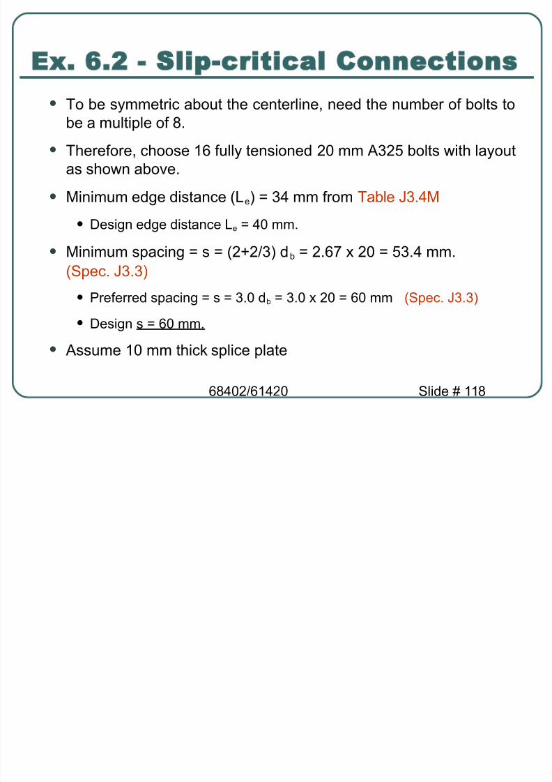
( To %e symmetric a%o*t the centerline need the n*m%er of %olts to%e a m*ltiple of 8&
( Therefore choose 16 f*lly tensioned 20 mm 9 2$ %olts 7ith layo*tas sho7n a%o5e&
(inim*m edge distance e ; 4 mm from Ta%le J &4
( Iesign edge distance e ; 40 mm&
( inim*m spacing ; s ; 2P2/ d % ; 2&6 20 ; $ &4 mm&Spec& J &
( .referred spacing ; s ; &0 d % ; &0 20 ; 60 mm Spec& J &( Iesign s ; 60 mm&
( 9ss*me 10 mm thic, splice plate
#1 2 $ Sli!$critical Connections

8/19/2019 Steel_Ch6 - Connections2
http://slidepdf.com/reader/full/steelch6-connections2 119/128
68402/61420 Slide # 11
#1 2 $ Sli!$critical Connections
Step /" Connection strength at factored loads( The splice connection sho*ld %e designed as a normal
shear/%earing connection %eyond this point for the factored load of600 ,@&
(Shear strength of a %olt ; &8 ,@ see E ample &1
( The shear strength of %olts ; &8 ,@/%olt 8 ; 622&4 ,@
( Bearing strength of 20 mm %olts at edge holes e ; 0 mm ; 6 &1,@ see E ample &1
( Bearing strength of 20 mm %olts at non:edge holes s ; 60 mm ;1 8&2 ,@ see E ample &1
( Bearing strength of %olt holes in flanges of 7ide flange section
( ; 4 6 &1 P 4 1 8&2 ; 82 &2 ,@ = 600 ,@ Q
#1 2 $ Sli!$critical Connections

8/19/2019 Steel_Ch6 - Connections2
http://slidepdf.com/reader/full/steelch6-connections2 120/128
68402/61420 Slide # 120
#1 2 $ Sli!$critical Connections
Step /" Iesign the splice plate( Tension yielding 0& 9 g F y = 00 ,@Y Therefore 9 g = 1 44 mm 2
( Tension fract*re 0& $ 9 n F * = 00 ,@
( Therefore 9 n ;9 g : 2 20 P &2 10 = 1000 mm 2
( Beam flange 7idth ; 166 mm
( 9ss*me plate 7idth 160 mm 10 mm 7hich has 9 g ; 1660 mm 2
Step / " Chec, mem%er strength
( St*dent on his/her o7n&
'lti"ate Strength Anal)sis of# t i B lt d C ti

8/19/2019 Steel_Ch6 - Connections2
http://slidepdf.com/reader/full/steelch6-connections2 121/128
68402/61420 Slide # 121
#ccentric Bolted ConnectionsE perimental st&dy $y Cra% ord and &la( <+-#+= sho%ed2 F
e
? The load?de ormation relationshipo any $olt is non?linear
A:SC Man&al 1art #
'lti"ate Strength Anal)sis of#ccentric Bolted Connections

8/19/2019 Steel_Ch6 - Connections2
http://slidepdf.com/reader/full/steelch6-connections2 122/128
68402/61420 Slide # 122
#ccentric Bolted ConnectionsThe ollo%ing concl&sions %ere also sho%n2
Fail&re rotation does not happen aro&nd the elastic center $&taro&nd an instantaneo&s centre <:C=
The :C does not coincide %ith the EC
The de ormation o each $olt is proportional to its distance romthe :C
Similar to the elastic analysis3 the connection capacity isgoverned $y the orce in the arthest $olt
F
e
D M
ir #$
@$
e F
e′
'lti"ate Strength Anal)sis of#ccentric Bolted Connections
8/19/2019 Steel_Ch6 - Connections2
http://slidepdf.com/reader/full/steelch6-connections2 123/128
68402/61420 Slide # 12
ma*ma*
∆=∆r r b
b
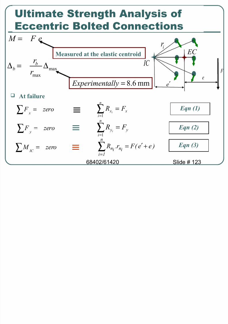
e F M =#ccentric Bolted Connections
mm6.,=all) #(peri ent
Meas&red at the elastic centroid
At ail&re
(
n
i ( F R
i=∑
=1D ,ero F (
=∑
D ,ero F )
=∑
D ,ero M @$
=∑
)
n
i ) F R i =∑=1
3ee6 F r ; R in
n
&iin +′=∑
=
@<n (-
@<n "-
@<n !-
ir #$ @$
e F
e′
'lti"ate Strength Anal)sis of#ccentric Bolted Connections

8/19/2019 Steel_Ch6 - Connections2
http://slidepdf.com/reader/full/steelch6-connections2 124/128
68402/61420 Slide # 124
#ccentric Bolted Connections
There ore3 getting the ma im&m orce in the arthest $olt re)&iresdetermining the &n(no%n 6e 7
Beca&se o the non?linear relationship3 e can $e determined $y trialand error
A spreadsheet can $e &sed to determine e
ir #$ @$
e F
e′
.orces on #ccentricall)$ oaded Boltswith #ccentricit) on the a)ing Surface

8/19/2019 Steel_Ch6 - Connections2
http://slidepdf.com/reader/full/steelch6-connections2 125/128
68402/61420 Slide # 12$
Ultimate Strength =ethod ,?nstantaneous Center of:otation =ethod0
: ) : ult ,/ $ e !+&1I3 ∆ 0+&55
with #ccentricit) on the .a)ing Surface
C IC
1 2
' !
ee4 & u
d & d 2
d 'd
/ (
/ "
/ % / !
R - ominal shear strength of 1 bolt at a deformation ∆#
Rult - Gltimate shear strength of 1 bolt#
∆ "otal deformation# including shear# bearing and bending deformation in the bolt and bearingdeformation of the connected elements# in. ( ∆ a( - H;5
for 20 mm AS!M A'2. bolt3∆& /d & - ∆2 /d 2 - I - ∆ a( /d a(
e - 2;<&HI base of the natural logarithm
'lti"ate Strength Method <InstantaneousCenter of ?otation Method=

8/19/2019 Steel_Ch6 - Connections2
http://slidepdf.com/reader/full/steelch6-connections2 126/128
68402/61420 Slide # 126
Center of ?otation Method=
9rial and error>( 9ss*me eJ
( Comp*te ∆i ) d i ∆ma" 6d ma" ∆ma" is ass*med for %olt at farthestdistance from )C
(Comp*te : i ): ult ,/! e !+&1I3∆i 0+&55
( Chec, for % u) Σ :d06,eJ.e0
( )f not satisfied repeat 7ith another eJ
λ µ )1( be R Rult b
∆−−=
ma*
ma*
∆=∆r
r bb
#1 6 4 - #ccentric Connections -'lti"ate Method

8/19/2019 Steel_Ch6 - Connections2
http://slidepdf.com/reader/full/steelch6-connections2 127/128
68402/61420 Slide # 12
lti ate MethodIetermine the largest eccentric force % u for 7hich the designshear strength of the %olts in the connection is ade *ate *singthe )C method& Kse %earing:type 20 mm 9 2$N %olts
C IC
1 2
' !
e - &00e4-50
& u
d & d 2
d 'd
/ (
/ "
/ % / !
75mm
75mm
>esign shear strength per bolt ( *. 7 1)
Ru - φ Rn- <<;H 1N
fter se3eral trials# assume e4- 60 mm.Bolts 2 and ! are furthest from the HI#therefore ∆2 - ∆ - ∆ a( - H;5
Iompute ∆i and Ri in tabulated form4
$ mm
#1 6 4 - #ccentric Connections -'lti"ate Method

8/19/2019 Steel_Ch6 - Connections2
http://slidepdf.com/reader/full/steelch6-connections2 128/128
lti ate Method0olt
1
h
*mm+
!
*mm+d *mm+
*mm+? *k&+ ? *k&+ ?d
*k&.mm+1 22&$ $ 8& $&4 2& 20& $6 2
2 &$ $ 12 8&6 &8 61&6 $8$
22&$ $ 8& $&4 2& 20& $6 2
4 &$ $ 12 8&6 &8 61&6 $8$
=&# "&3
= 2# 3
Ihec 4
P u- (Σ Rd )/(e4 e) (2655!/(60J100))