step 2: convert the cad geo - به نام یگانه ... filestep 2: convert the cad geometry into...
TRANSCRIPT
Step 2: Convert the CAD Geometry into Airpak Objects Now that you have imported the CAD geometry into Airpak, the next step is to convert it intoAirpak objects. You will do this by selecting groups of surfaces and converting them into Airpak objects.
1. Create a block to represent the person.
In this simplified model, the person will be modeled as a block object.
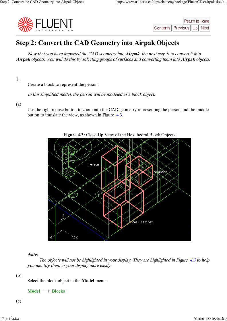
(a)Use the right mouse button to zoom into the CAD geometry representing the person and the middlebutton to translate the view, as shown in Figure 4.3.
Figure 4.3: Close-Up View of the Hexahedral Block Objects
Note: The objects will not be highlighted in your display. They are highlighted in Figure 4.3 to helpyou identify them in your display more easily.
(b)Select the block object in the Model menu.
Model Blocks
(c)
Step 2: Convert the CAD Geometry into Airpak Objects http://www.ualberta.ca/dept/chemeng/package/FluentCDs/airpak-doc/a...
1 از 17 ق.ظ 08:04 2010/01/22 ٔصفحه

Select the shape that you want Airpak to try to fit to the CAD geometry.
Model CAD import Options
Airpak will open the CAD import options panel.
i.Under Try shapes, deselect circ, cyl, incline, polygon, and quad.
This will ensure that the person is created as a rectangular prism block.
ii.Click Accept.
(d)Create the person block.
Model CAD import Selected -> objects
i.Using the left mouse button, click on three of the six surfaces that comprise the person(shown in Figure 4.3) in the graphics window.
Hint: If you select the wrong CAD geometry, click the right mouse button in the graphicswindow to undo your selection.
ii.
Step 2: Convert the CAD Geometry into Airpak Objects http://www.ualberta.ca/dept/chemeng/package/FluentCDs/airpak-doc/a...
2 از 17 ق.ظ 08:04 2010/01/22 ٔصفحه

Click the middle mouse button in the graphics window to complete the creation of the block.
An Airpak block object will be displayed in the graphics window.
(e)Specify a name for the block.
i.Select UNNAMED in the block Edit panel.
ii.Enter the name person in the Name field.
iii.Click Modify.
2. Create a block to represent the computer.
(a)Using the left mouse button, click on three of the six surfaces that comprise the computer (shown inFigure 4.3) in the graphics window.
Hint: If you select the wrong CAD geometry, click the right mouse button in the graphics windowto undo your selection.
(b)Click the middle mouse button in the graphics window to complete the creation of the block.
An Airpak block object will be displayed in the graphics window.
(c)Specify a name for the block.
i.Select UNNAMED in the block Edit panel.
ii.Enter the name computer in the Name field.
iii.Click Modify.
3. Create a block to represent the desk cabinet.
(a)Using the left mouse button, click on three of the six surfaces that comprise the desk cabinet (shownin Figure 4.3) in the graphics window.
(b)Click the middle mouse button in the graphics window to complete the creation of the block.
An Airpak block object will be displayed in the graphics window.
(c)
Step 2: Convert the CAD Geometry into Airpak Objects http://www.ualberta.ca/dept/chemeng/package/FluentCDs/airpak-doc/a...
3 از 17 ق.ظ 08:04 2010/01/22 ٔصفحه
Click the middle mouse button in the graphics window again to exit the Selected -> objects mode.
You need to exit the Selected -> objects mode if you want to use the mouse for viewmanipulation (as you will do in the next step).
Extra: Alternatively, you can toggle between manipulating the view of the room and the Selected ->objects mode using the F9 key. This is useful in cases where you are creating many of the sametype of Airpak objects out of the existing CAD geometry. Using F9 will prevent you from having torepeatedly enter and exit the Selected -> objects mode.
(d)Specify a name for the block.
i.Select UNNAMED in the block Edit panel.
ii.Enter the name desk-cabinet in the Name field.
iii.Click Modify.
4. Create a cylindrical block to represent the table leg.
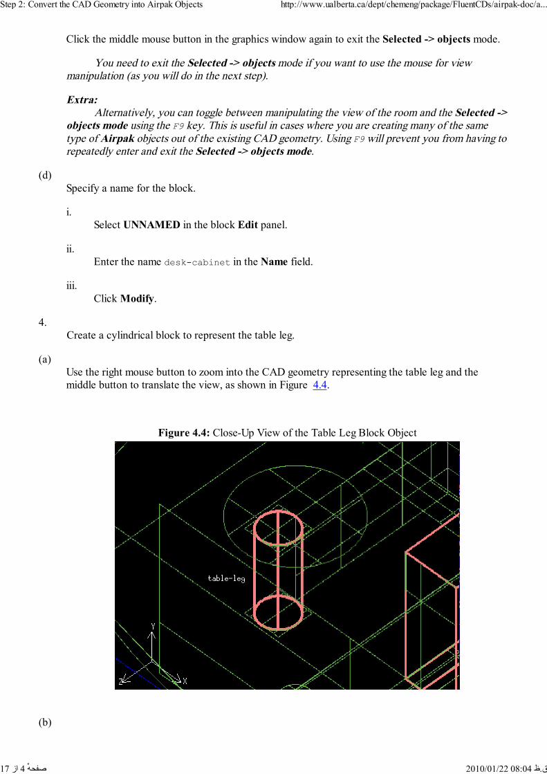
(a)Use the right mouse button to zoom into the CAD geometry representing the table leg and themiddle button to translate the view, as shown in Figure 4.4.
Figure 4.4: Close-Up View of the Table Leg Block Object
(b)
Step 2: Convert the CAD Geometry into Airpak Objects http://www.ualberta.ca/dept/chemeng/package/FluentCDs/airpak-doc/a...
4 از 17 ق.ظ 08:04 2010/01/22 ٔصفحه

Select the shape that you want Airpak to try to fit to the CAD geometry.
Model CAD import Options
i.Under Try shapes in the CAD import options panel, deselect hexa and select cyl.
This will ensure that the table leg is created as a cylindrical block.
ii.Click Accept.
(c)Create the table leg block.
Model CAD import Selected -> objects
i.Using the left mouse button, click on the top, the bottom, and the side of the table leg (shownin Figure 4.4) in the graphics window.
Hint: If you select the wrong CAD geometry, click the right mouse button in the graphicswindow to undo your selection.
ii.Click the middle mouse button in the graphics window to complete the creation of the block.
After a few moments, an Airpak block object will be displayed in the graphicswindow.
iii.Click the middle mouse button in the graphics window again to exit the Selected -> objectsmode.
(d)Specify a name for the block.
i.Select UNNAMED in the block Edit panel.
ii.Enter the name table-leg in the Name field.
iii.Click Modify.
5. Create a cylindrical block to represent the room.
(a)Use the right mouse button to zoom out of the CAD geometry representing the room and the middlebutton to translate the view, as shown in Figure 4.5.
Step 2: Convert the CAD Geometry into Airpak Objects http://www.ualberta.ca/dept/chemeng/package/FluentCDs/airpak-doc/a...
5 از 17 ق.ظ 08:04 2010/01/22 ٔصفحه

Figure 4.5: Close-Up View of the Room Block Object
(b)Create the room block.
Model CAD import Selected -> objects
i.Using the left mouse button, click on the top, the bottom, and the side of the room (shown inFigure 4.5) in the graphics window.
Hint: If you select the wrong CAD geometry, click the right mouse button in the graphicswindow to undo your selection.
ii.Click the middle mouse button in the graphics window to complete the creation of the block.
After a few moments, an Airpak block object will be displayed in the graphicswindow.
iii.Click the middle mouse button in the graphics window again to exit the Selected -> objectsmode.
(c)Specify a name for the block.
i.Select UNNAMED in the block Edit panel.
ii.Enter the name fluid-room in the Name field.
iii.
Step 2: Convert the CAD Geometry into Airpak Objects http://www.ualberta.ca/dept/chemeng/package/FluentCDs/airpak-doc/a...
6 از 17 ق.ظ 08:04 2010/01/22 ٔصفحه

Click Modify.
6. Create an inlet fan using the CAD geometry.
(a)Use the right mouse button to zoom into the CAD geometry representing the fan and the middlebutton to translate the view, as shown in Figure 4.6.
Figure 4.6: Close-Up View of the Fan Object
(b)Select the fan object in the Model menu.
Model Fans
(c)Select the shape that you want Airpak to try to fit to the CAD geometry.
Model CAD import Options
i.Under Try shapes in the CAD import options panel, deselect cyl and select circ.
This will ensure that the fan is created as a circle.
ii.Click Accept.
(d)Create the inlet fan.
Model CAD import Selected -> objects
Step 2: Convert the CAD Geometry into Airpak Objects http://www.ualberta.ca/dept/chemeng/package/FluentCDs/airpak-doc/a...
7 از 17 ق.ظ 08:04 2010/01/22 ٔصفحه

i.Using the left mouse button, click on the circle that comprises the inlet fan (shown in Figure 4.6) in the graphics window.
Hint: If you select the wrong CAD geometry, click the right mouse button in the graphicswindow to undo your selection.
ii.Click the middle mouse button in the graphics window to complete the creation of the fan.
An Airpak fan object will be displayed in the graphics window.
iii.Click the middle mouse button in the graphics window again to exit the Selected -> objectsmode.
(e)Specify a name for the fan.
i.Select UNNAMED.1 in the fan Edit panel.
ii.Enter the name floor-diffuser in the Name field.
iii.Click Modify.
7. Create an exhaust vent using the CAD geometry.
(a)Use the right mouse button to zoom into the CAD geometry representing the vent and the middlebutton to translate the view, as shown in Figure 4.7.
Step 2: Convert the CAD Geometry into Airpak Objects http://www.ualberta.ca/dept/chemeng/package/FluentCDs/airpak-doc/a...
8 از 17 ق.ظ 08:04 2010/01/22 ٔصفحه
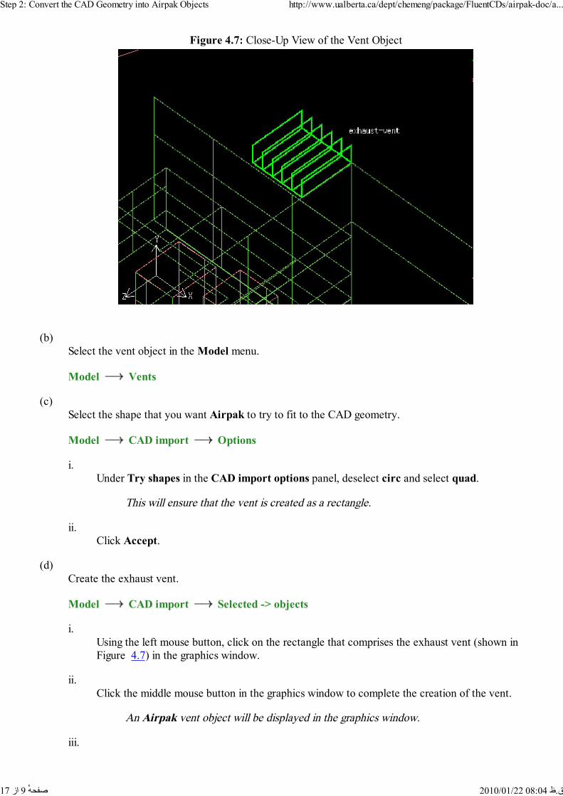
Figure 4.7: Close-Up View of the Vent Object
(b)Select the vent object in the Model menu.
Model Vents
(c)Select the shape that you want Airpak to try to fit to the CAD geometry.
Model CAD import Options
i.Under Try shapes in the CAD import options panel, deselect circ and select quad.
This will ensure that the vent is created as a rectangle.
ii.Click Accept.
(d)Create the exhaust vent.
Model CAD import Selected -> objects
i.Using the left mouse button, click on the rectangle that comprises the exhaust vent (shown inFigure 4.7) in the graphics window.
ii.Click the middle mouse button in the graphics window to complete the creation of the vent.
An Airpak vent object will be displayed in the graphics window.
iii.
Step 2: Convert the CAD Geometry into Airpak Objects http://www.ualberta.ca/dept/chemeng/package/FluentCDs/airpak-doc/a...
9 از 17 ق.ظ 08:04 2010/01/22 ٔصفحه
Click the middle mouse button in the graphics window again to exit the Selected -> objectsmode.
(e)Specify a name for the vent.
i.Select UNNAMED.1 in the vent Edit panel.
ii.Enter the name exhaust-vent in the Name field.
iii.Click Modify.
8. Create a doorway.
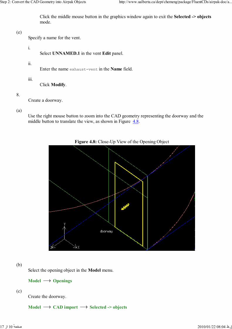
(a)Use the right mouse button to zoom into the CAD geometry representing the doorway and themiddle button to translate the view, as shown in Figure 4.8.
Figure 4.8: Close-Up View of the Opening Object
(b)Select the opening object in the Model menu.
Model Openings
(c)Create the doorway.
Model CAD import Selected -> objects
Step 2: Convert the CAD Geometry into Airpak Objects http://www.ualberta.ca/dept/chemeng/package/FluentCDs/airpak-doc/a...
10 از 17 ق.ظ 08:04 2010/01/22 ٔصفحه

i.Using the left mouse button, click on the rectangle that comprises the doorway (shown inFigure 4.8) in the graphics window.
ii.Click the middle mouse button in the graphics window to complete the creation of theopening.
An Airpak opening object will be displayed in the graphics window.
iii.Click the middle mouse button in the graphics window again to exit the Selected -> objectsmode.
(d)Specify a name for the opening.
i.Select UNNAMED.1 in the opening Edit panel.
ii.Enter the name doorway in the Name field.
iii.Click Modify.
9. Create two walls using the CAD geometry.
(a)Use the right mouse button to zoom out of the CAD geometry representing the walls and the middlebutton to translate the view, as shown in Figure 4.9.
Figure 4.9: Close-Up View of the Wall Objects
Step 2: Convert the CAD Geometry into Airpak Objects http://www.ualberta.ca/dept/chemeng/package/FluentCDs/airpak-doc/a...
11 از 17 ق.ظ 08:04 2010/01/22 ٔصفحه

(b)Select the wall object in the Model menu.
Model Walls
(c)Create the first wall.
Model CAD import Selected -> objects
i.Using the left mouse button, click on the rectangle that comprises the first wall in the graphicswindow, identified as wall-1 in Figure 4.9.
ii.Click the middle mouse button in the graphics window to complete the creation of the wall.
An Airpak wall object will be displayed in the graphics window.
(d)Specify a name for the wall.
i.Select UNNAMED.1 in the wall Edit panel.
ii.Enter the name wall-1 in the Name field.
iii.Click Modify.
(e)Repeat steps (c) and (d) for the second wall ( wall-2).
(f)Click the middle mouse button in the graphics window to exit the Selected -> objects mode
10. Create cubicle partitions using the CAD geometry.
(a)Use the right mouse button to zoom into the CAD geometry representing the partitions and themiddle button to translate the view, as shown in Figure 4.10.
Step 2: Convert the CAD Geometry into Airpak Objects http://www.ualberta.ca/dept/chemeng/package/FluentCDs/airpak-doc/a...
12 از 17 ق.ظ 08:04 2010/01/22 ٔصفحه

Figure 4.10: Close-Up View of the Partition Objects
(b)Select the partition object in the Model menu.
Model Partitions
(c)Create the low partition.
Model CAD import Selected -> objects
i.Using the left mouse button, click on the rectangle that comprises the low partition in thegraphics window, identified as low-partition in Figure 4.10.
ii.Click the middle mouse button in the graphics window to complete the creation of thepartition.
An Airpak partition object will be displayed in the graphics window.
(d)Specify a name for the partition.
i.Select UNNAMED.1 in the partition Edit panel.
ii.Enter the name low-partition in the Name field.
iii.Click Modify.
(e)
Step 2: Convert the CAD Geometry into Airpak Objects http://www.ualberta.ca/dept/chemeng/package/FluentCDs/airpak-doc/a...
13 از 17 ق.ظ 08:04 2010/01/22 ٔصفحه

Repeat steps (c) and (d) for the remaining three partitions ( hi-partition-1, hi-partition-2,and hi-partition-3).
(f)Click the middle mouse button in the graphics window to exit the Selected -> objects mode.
11. Create rectangular tabletops using the CAD geometry.
(a)Click Orient in the Options menu and select Negative Y from the drop-down list.
(b)Use the right mouse button to zoom into the CAD geometry representing the partitions and themiddle button to translate the view, as shown in Figure 4.11.
Figure 4.11: Close-Up View of the Rectangular Tabletop Objects
(c)Create two rectangular tabletops.
For simplicity, in this step you will split a single L-shaped CAD surface into two Airpakpartition objects.
Model CAD import Regions -> objects
i.Using the left mouse button, click on the L-shaped object that comprises the tabletop (shownin Figure 4.11) in the graphics window.
ii.Click the middle mouse button in the graphics window to accept the selection of thetabletops.
Step 2: Convert the CAD Geometry into Airpak Objects http://www.ualberta.ca/dept/chemeng/package/FluentCDs/airpak-doc/a...
14 از 17 ق.ظ 08:04 2010/01/22 ٔصفحه

iii.Position the mouse pointer (which is now a ``+'') on the line just beneath the blockrepresenting the person and press the h key on the keyboard to draw a horizontal line.
iv.Click the middle mouse button in the graphics window to accept the division of the region.
Airpak will open the Multiple regions panel.
v.Click Split to split the region into two partitions.
Two Airpak partition objects will be displayed in the graphics window.
vi.Click the middle mouse button in the graphics window again to exit the Regions -> objectsmode.
(d)Specify names for the partitions.
i.Select UNNAMED.1 in the partition Edit panel.
ii.Enter the name tabletop-1 in the Name field.
iii.Click Modify.
iv.Repeat steps i-iii for UNNAMED.2 ( tabletop-2).
12. Create a circular tabletop.
(a)Click on Orient in the Options menu and select Isometric from the Orient drop-down list.
(b)Use the right mouse button to zoom into the CAD geometry representing the circular tabletop and
Step 2: Convert the CAD Geometry into Airpak Objects http://www.ualberta.ca/dept/chemeng/package/FluentCDs/airpak-doc/a...
15 از 17 ق.ظ 08:04 2010/01/22 ٔصفحه
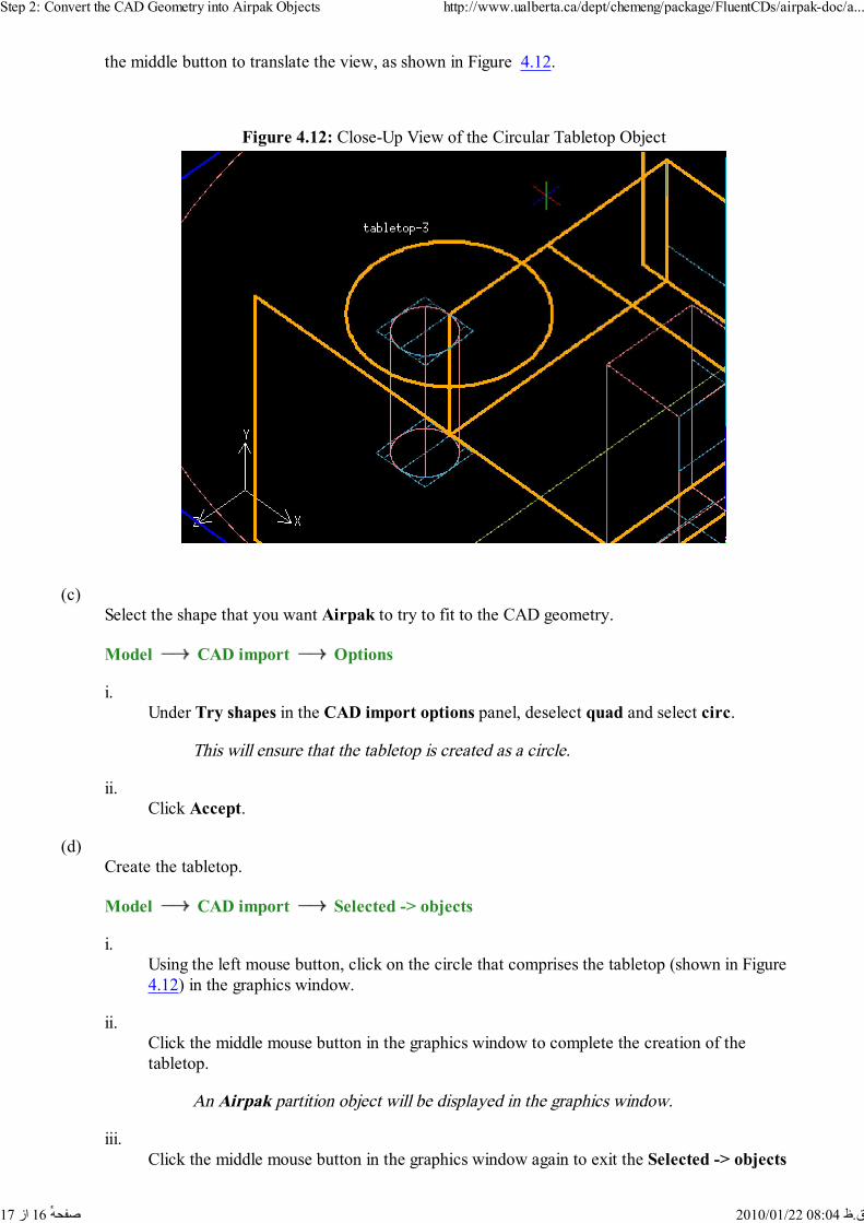
the middle button to translate the view, as shown in Figure 4.12.
Figure 4.12: Close-Up View of the Circular Tabletop Object
(c)Select the shape that you want Airpak to try to fit to the CAD geometry.
Model CAD import Options
i.Under Try shapes in the CAD import options panel, deselect quad and select circ.
This will ensure that the tabletop is created as a circle.
ii.Click Accept.
(d)Create the tabletop.
Model CAD import Selected -> objects
i.Using the left mouse button, click on the circle that comprises the tabletop (shown in Figure 4.12) in the graphics window.
ii.Click the middle mouse button in the graphics window to complete the creation of thetabletop.
An Airpak partition object will be displayed in the graphics window.
iii.Click the middle mouse button in the graphics window again to exit the Selected -> objects
Step 2: Convert the CAD Geometry into Airpak Objects http://www.ualberta.ca/dept/chemeng/package/FluentCDs/airpak-doc/a...
16 از 17 ق.ظ 08:04 2010/01/22 ٔصفحه
mode.
(e)Specify a name for the tabletop.
i.Select UNNAMED.1 in the partition Edit panel.
ii.Enter the name tabletop-3 in the Name field.
iii.Click Modify.
13. Remove all of the remaining CAD geometry from your Airpak model.
Model CAD import Delete all CAD data
(a)Click Yes to confirm the removal of all remaining CAD surfaces.
Previous: Step 1: Open aUp: Room and Office SpaceNext: Step 3: Create Other© Fluent Inc. 2002-02-27
Step 2: Convert the CAD Geometry into Airpak Objects http://www.ualberta.ca/dept/chemeng/package/FluentCDs/airpak-doc/a...
17 از 17 ق.ظ 08:04 2010/01/22 ٔصفحه