stephanos dritsos_‘seismic assessment and retrofitting of structures_ eurocode8-part3 and the...
DESCRIPTION
Seismic Assessment and Retrofitting of StructuresTRANSCRIPT
Seismic Assessment and Retrofitting of Structures:Eurocode8‐Part3 and the Greek Code on Seismic Structural
Interventions
Prof. Stephanos E. Dritsos, University of Patras, Greece
Working Group 7: Earthquake Resistant Structures Geneva, 25 September 2015

2
CONTENT
• Introduction
• Performance Levels or Damage Levels
• Elements‘ Behaviour
• Documentation
• Methods of Analysis
• Seismic Strengthening Strategies - Methods of Strengthening the
Whole Structure
• Composite Elements

3
INTRODUCTION

4
EUROCODESEuropean Standard (EN) for the Design
EN 1990 Eurocode 0:Basis of Structural DesignEN 1991 Eurocode 1:Actions on structures EN 1992 Eurocode 2:
Design of concrete structures
EN 1993 Eurocode 3:Design of steel structuresEN 1994 Eurocode 4:
EN 1995 Eurocode 5: Design of timber structures
EN 1999 Eurocode 9:
Design of aluminium structures
EN 1997 Eurocode 7:Geotechnical design
EN 1998 Eurocode 8:
Design of structures for earthquake resistance
EN 1996 Eurocode 6: Design of masonry structures
Design of composite steel and concrete structures

5
Eurocode 8- Design of structures for earthquake resistance
1: ΕΝ1998-1 General rules, seismic actions and rules for buildings
2: ΕΝ1998-2 Bridges
3: ΕΝ1998-3 Assessment and retrofitting of buildings
4: ΕΝ1998-4 Silos, tanks and pipelines
5: ΕΝ1998-5 Foundations, retaining structures and geotechnical aspects
6: ΕΝ1998-6 Towers, masts and chimneys

6
1983
19951996
2000
2003
200520062007
20122008
EUROPE U.S.A.CODE ENVIRONMENT
CEB Bul. No. 162, “Assessment of Concrete Structures and Design Procedures for Upgrading (Redesign)”.
EC 8-Part 1.4, “Eurocode 8: Design Provisions for Earthquake Resistance of Structures: Part 1-4: Strengthening and Repair of Buildings”
ATC 40.“Seismic Evaluation and Retrofit of Concrete Buildings”.
FEMA 356. “Prestandard and Commentary for the Seismic Rehabilitation of Buildings”.
fib Bul.No24, “Seismic Assessment and Retrofit of Reinforced Concrete Buildings”.
EC 8-Part3, “Eurocode 8: Design of Structures forEarthquake Resistance. Part 3: Assessment
and Retrofitting of Buildings”. Draft No 5.
GCSI, “Greek Code of Structural Interventions”. ASCE/SEI 41, ASCE Standards SeismicRehabilitationof Existing Buildings.ASCE/SEI 41, Supplement1, Update ASCE/SEI 41.
GCSI, Draft
7
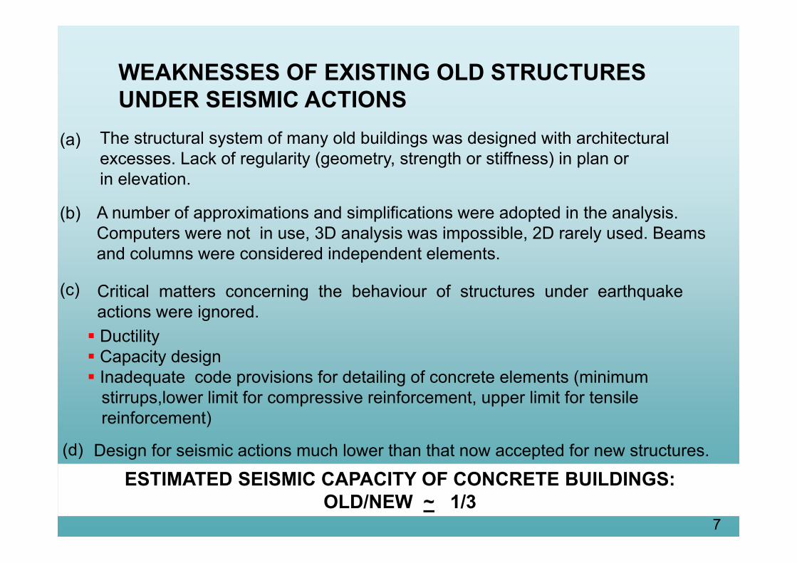
WEAKNESSES OF EXISTING OLD STRUCTURESUNDER SEISMIC ACTIONS
Critical matters concerning the behaviour of structures under earthquakeactions were ignored.
The structural system of many old buildings was designed with architecturalexcesses. Lack of regularity (geometry, strength or stiffness) in plan orin elevation.
A number of approximations and simplifications were adopted in the analysis.Computers were not in use, 3D analysis was impossible, 2D rarely used. Beamsand columns were considered independent elements.
(a)
(b)
(c)
Design for seismic actions much lower than that now accepted for new structures.
ESTIMATED SEISMIC CAPACITY OF CONCRETE BUILDINGS: OLD/NEW ~ 1/3
Ductility Capacity design Inadequate code provisions for detailing of concrete elements (minimum
stirrups,lower limit for compressive reinforcement, upper limit for tensilereinforcement)
(d)
8
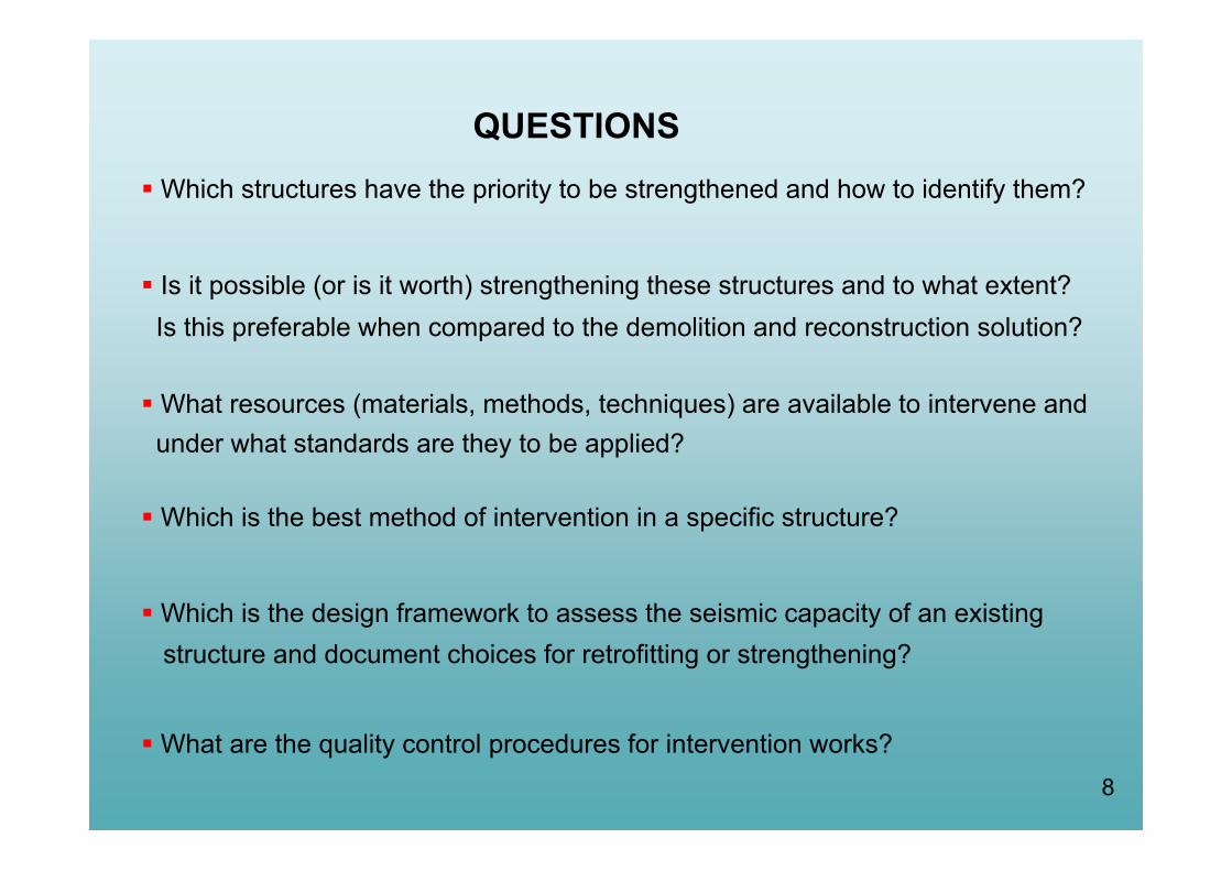
QUESTIONS Which structures have the priority to be strengthened and how to identify them?
Is it possible (or is it worth) strengthening these structures and to what extent?Is this preferable when compared to the demolition and reconstruction solution?
What resources (materials, methods, techniques) are available to intervene andunder what standards are they to be applied?
Which is the best method of intervention in a specific structure?
Which is the design framework to assess the seismic capacity of an existingstructure and document choices for retrofitting or strengthening?
What are the quality control procedures for intervention works?
9
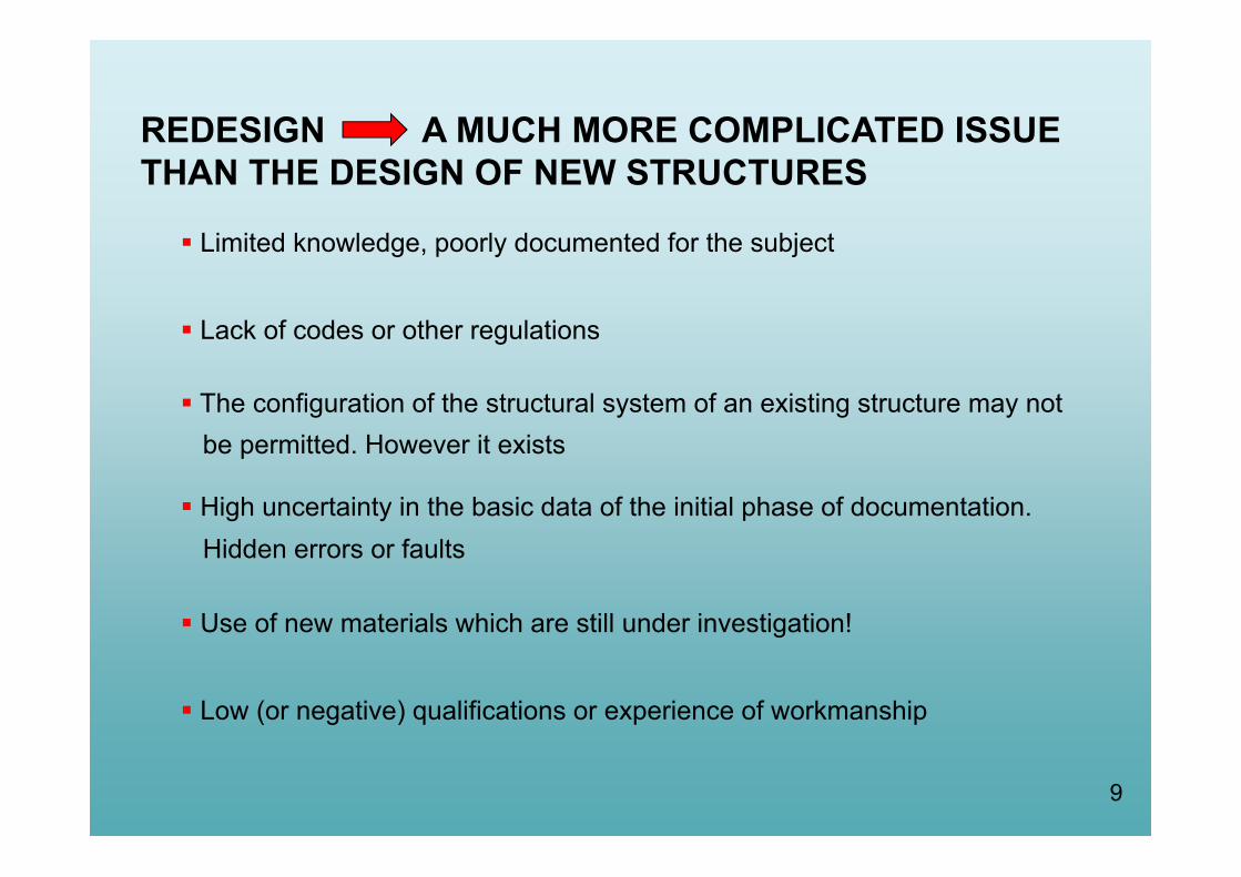
REDESIGN A MUCH MORE COMPLICATED ISSUE THAN THE DESIGN OF NEW STRUCTURES
Limited knowledge, poorly documented for the subject
Lack of codes or other regulations
The configuration of the structural system of an existing structure may notbe permitted. However it exists
High uncertainty in the basic data of the initial phase of documentation.Hidden errors or faults
Use of new materials which are still under investigation!
Low (or negative) qualifications or experience of workmanship

Why we need a new design framework in addition to the existing one for new structures?
Existing Structures:(a) Reflect the state of knowledge at the time of their construction
(b) May contain hidden gross errors(c) May have been stressed in previous earthquakes
(or other accidental actions) with unknown effectsStructural assessment and redesign of an existing structure due toa structural intervention are subjected to a different degree ofuncertainty than the design of a new structureDifferent material and structural safety factors are required
Different analysis procedures may be necessary depending on the
completeness and reliability of available dataUsually, analytical procedures (or software) used for the design ofnew structures are not suitable to assess existing structures. Newstructures designed according to new codes necessarily fulfil specific coderequirements for being analysed acceptably with conventional analyticalprocedures, e.g. linear elastic analysis 10

11
THREE MAIN OBJECTIVES
Assess the seismic capacity of an existing structure
Decide the necessary intervention work
Design the intervention work

12
ASSESSMENT PROCEDURE 1st stage Document the existing structure
2nd stage Assessment of the (seismic) capacity of the structure
3rd stage Decide if structural intervention required
4th stage Design the structural intervention
5th stage Construct the intervention work
Design in progress
13
PERFORMANCE LEVELS OR
DAMAGE LEVELS
14
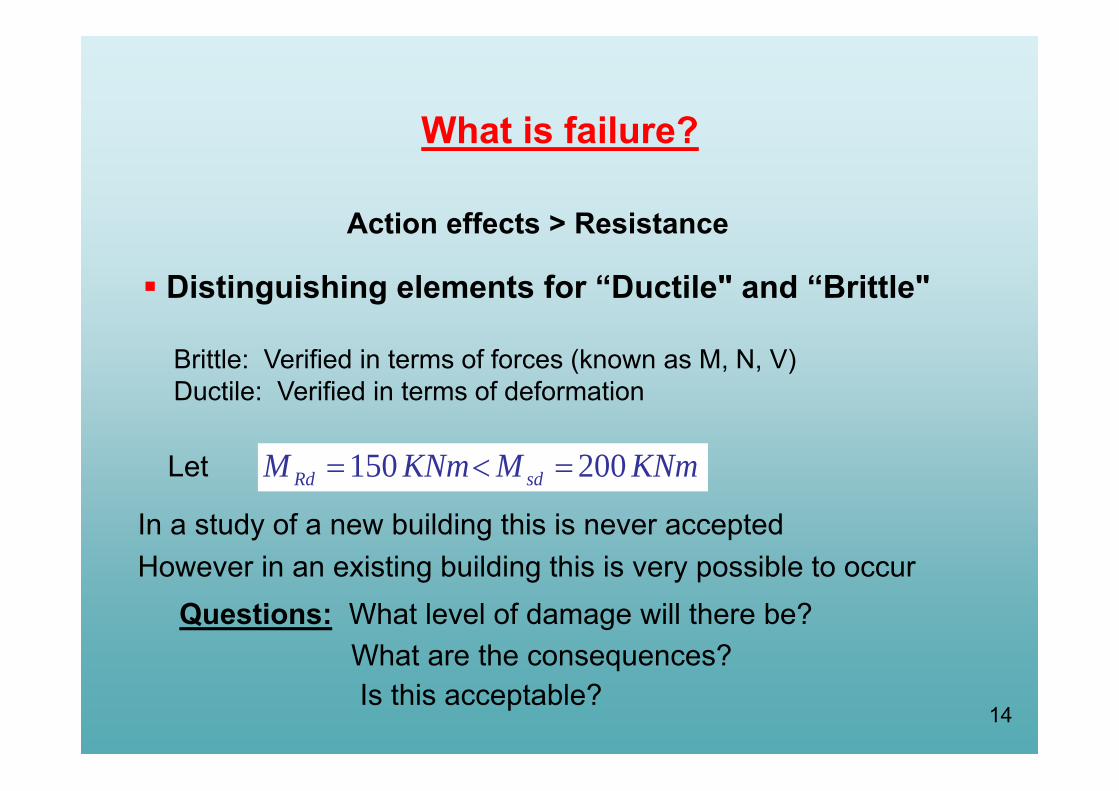
What is failure?
Action effects > Resistance
Let 150 200Rd sdM KNm M KNm
In a study of a new building this is never acceptedHowever in an existing building this is very possible to occur
Questions: What level of damage will there be?What are the consequences?Is this acceptable?
Distinguishing elements for “Ductile" and “Brittle"
Brittle: Verified in terms of forces (known as M, N, V)Ductile: Verified in terms of deformation

15
Damage Levels Performance Levels or Limit States (LS)
LS Level C of Near Collapse (NC)
Collapse prevention (other Codes e.g. FEMA):Extensive and serious or severe damage, buildingis very close to collapse
LS Level B of Significant Damage (SD)
Life Safety (other Codes e.g. FEMA): Buildingwith serious damage accepted as the designof new buildings
LS Level A Limitation Damage (DL)
Immediate Occupancy (other Codes e.g.FEMA): Minimal damage, elements have notsubstantially yielded

16
Acceptable Performance Levels or Level of Protection (e.g. State of Damage)of the Structure:
Level A: Immediately Occupancy (IO) or Damage Limitation (DL) Very light damage Structural elements retain their strength and stiffness No permanent drifts No significant cracking of infill walls Damage could be economically repaired
Level B: Life Safety (LS) or Significant Damage (SD) Significant damage to the structural system however retention
of some lateral strength and stiffness Vertical elements capable of sustaining vertical loads Infill walls severally damaged Moderate permanent drifts exist The structure can sustain moderate aftershocks The cost of repair may be high. The cost of reconstruction should be
examined as an alternative solution
PERFORMANCE LEVELS

17
Level C: Collapse Prevention (CP) or Near Collapse (NP)
Structure heavily damaged with low lateral strength and stiffness
Vertical elements capable of sustaining vertical loads
Most non-structural components have collapsed
Large permanent drifts
Structure is near collapse and possibly cannot survive a moderateaftershock
Uneconomical to repair. Reconstruction the most probable solution
PERFORMANCE LEVELS
18
V3123
123
123
123
V2 V1
V
δδ1 δ2δ3
V2
V1
V3
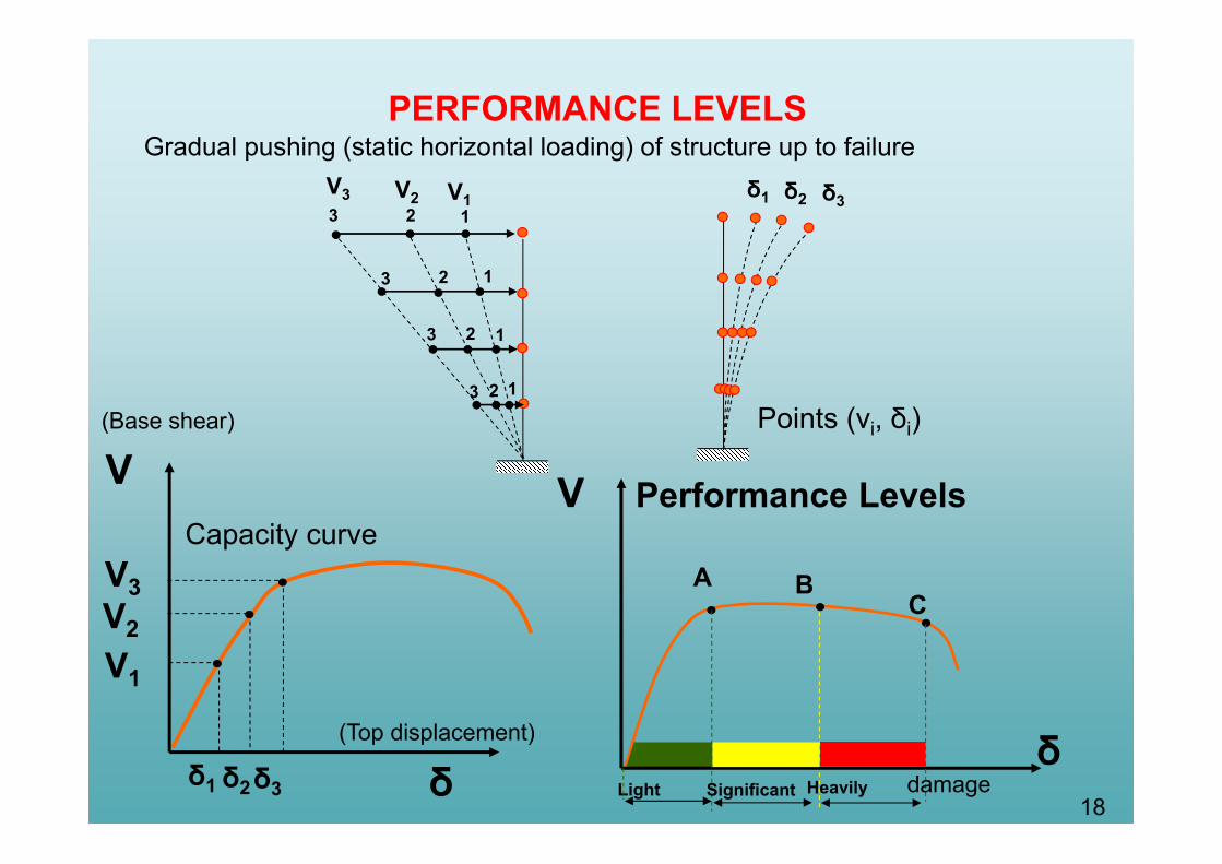
Capacity curve
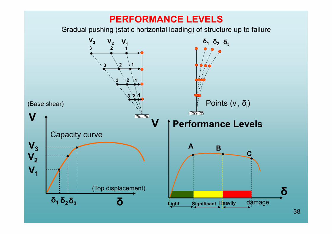
Gradual pushing (static horizontal loading) of structure up to failureδ1 δ2 δ3
Points (vi, δi)
V
PERFORMANCE LEVELS
δ
Performance Levels
A BC
damageLight Significant Heavily
(Base shear)
(Top displacement)
19
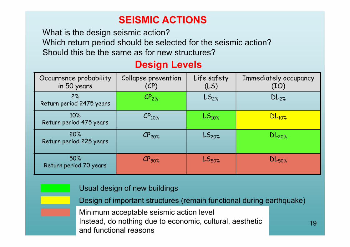
What is the design seismic action?Which return period should be selected for the seismic action?Should this be the same as for new structures?
Design Levels
SEISMIC ACTIONS
Occurrence probabilityin 50 years
Collapse prevention (CP)
Life safety(LS)
Immediately occupancy (IO)
2%Return period 2475 years
CP2% LS2% DL2%
10%Return period 475 years
CP10% LS10% DL10%
20%Return period 225 years
CP20% LS20% DL20%
50%Return period 70 years
CP50% LS50% DL50%
Usual design of new buildingsDesign of important structures (remain functional during earthquake)Minimum acceptable seismic action levelInstead, do nothing due to economic, cultural, aestheticand functional reasons
20
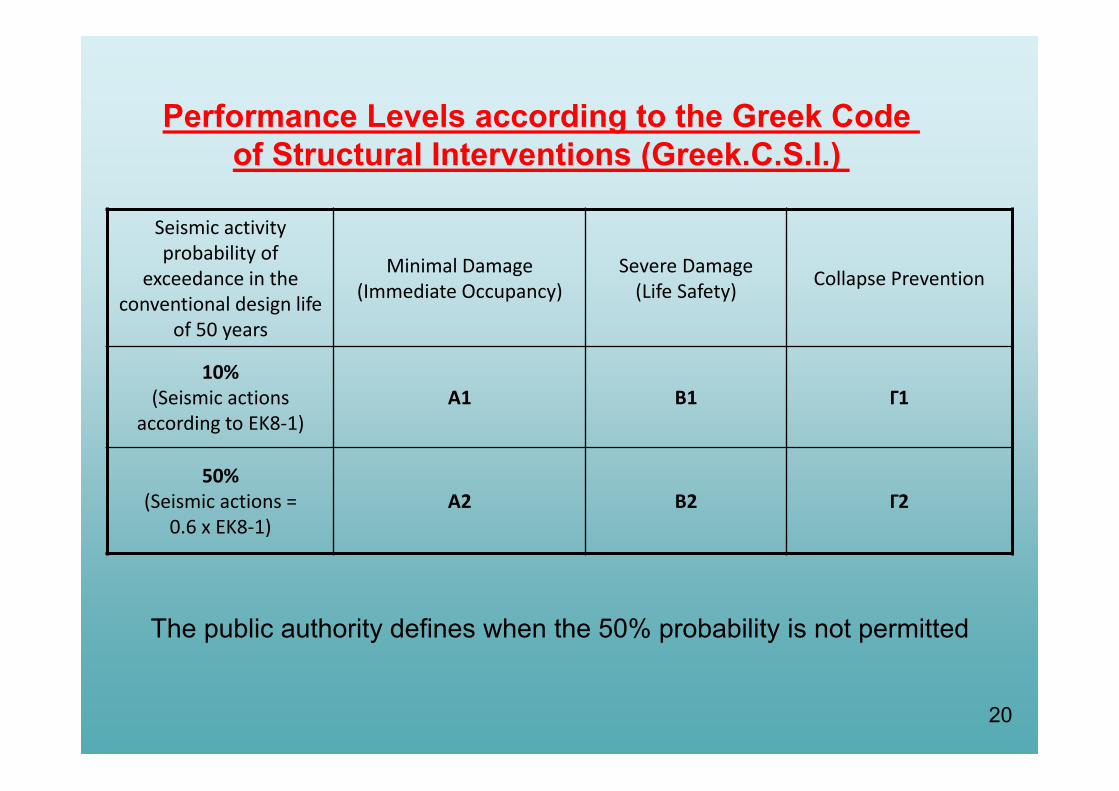
Seismic activity probability of
exceedance in the conventional design life
of 50 years
Minimal Damage(Immediate Occupancy)
Severe Damage(Life Safety) Collapse Prevention
10%(Seismic actions
according to ΕΚ8‐1)Α1 Β1 Γ1
50%(Seismic actions =
0.6 x ΕΚ8‐1)Α2 Β2 Γ2
The public authority defines when the 50% probability is not permitted
Performance Levels according to the Greek Code of Structural Interventions (Greek.C.S.I.)
21
ELEMENT’S BEHAVIOUR

22
ELEMENT BEHAVIOR
Ductile BrittleFlexure controlled
deformation demand
d dS R
deformation capacity
Seismically Primary
Shear controlled
d dS R
strength demand strength capacity
Seismically Secondary
“Secondary” seismic element More damage is acceptable for the same Performance Level Considered not participating in the seismic action resisting system.Strength and stiffness are neglected
Able to support gravity loads when subjected to seismic displacements
23
θy θu
θupl
θθd
Μd
y
m
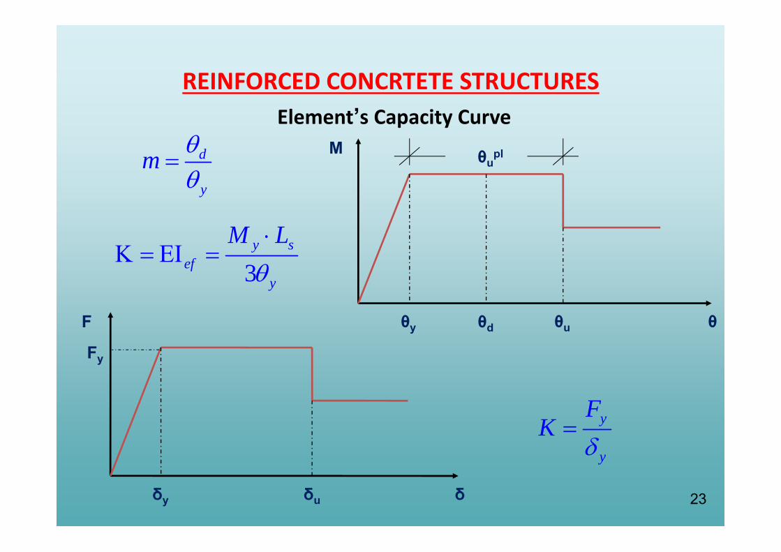
REINFORCED CONCRTETE STRUCTURESElement’s Capacity Curve
y
y
FK
3y s
efy
M L
δy δu δ
F
Fy
24
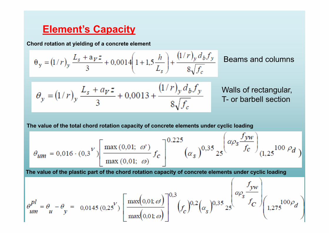
The value of the total chord rotation capacity of concrete elements under cyclic loading
Element’s CapacityChord rotation at yielding of a concrete element
Beams and columns
Walls of rectangular, T- or barbell section
The value of the plastic part of the chord rotation capacity of concrete elements under cyclic loading

25
d dS ≤ R
ELEMENT’S SAFETY VERIFICATIONInequality of Safety
dS is the design action effect
dR is the design resistance
For brittle components/mechanisms (e.g. shear) d dS , RFor ductile components/mechanisms (e.g. flexural) d dS , R
A Level (IO)
B Level (LS)
C Level (NC)
concern forces
concern deformations, Rdsd, θ θ
Rd yθ1
2y u
RdRd
θ “primary” elements
uRd
Rd
θ “secondary” elements
1,8Rd for “primary” elements
1,0Rd for “secondary” elementsu
RdRd
θ
θ
Μ
yθ ) / 2uy︵θ uθ
1,8Rd
1,8Rd
(G.S.I. Code)

26
Beams and Columns
rectangular web cross section circular cross section
Shear Walls
Short Columns (LV/h)≤2
ELEMENT’S SHEAR CAPACITY

27
DOCUMENTATION
28
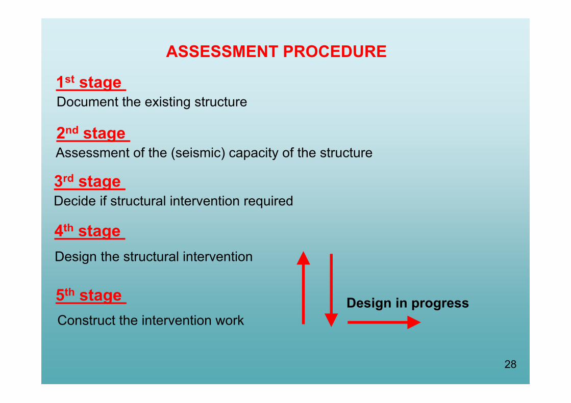
ASSESSMENT PROCEDURE
1st stage Document the existing structure
2nd stage Assessment of the (seismic) capacity of the structure
3rd stage Decide if structural intervention required
4th stage Design the structural intervention
5th stage Construct the intervention work
Design in progress

29
Documentation of an Existing Structure• Strength of materials• Reinforcement• Geometry (including foundation)• Actual loads• Past damage or “wear and tear” or defects
Knowledge Levels (KL)
Confidence factors (Other safety factors for existing materials and elements)
New safety factors for new materials
30
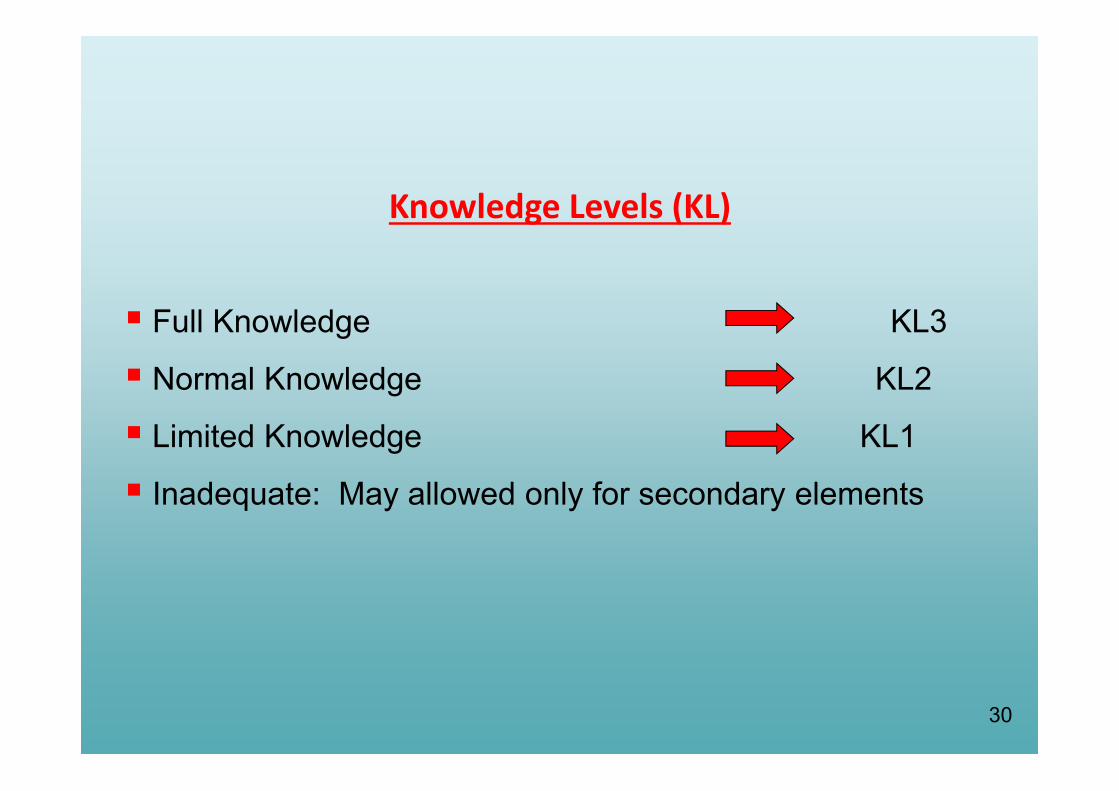
Knowledge Levels (KL)
Full Knowledge KL3
Normal Knowledge KL2
Limited Knowledge KL1
Inadequate: May allowed only for secondary elements

31
DOCUMENTATION Knowledge Levels and Confidence Factors
KL1: Limited KnowledgeKL2: Normal KnowledgeKL3: Full Knowledge
= 1.35
= 1.20
= 1.00

3232
Concrete (G.C.S.I.) Assessment methods fc:
Required number of specimens- Not all together, i.e. spread out over all floors and all components - At least 3 cores per alike component per two floors, definitely for the "critical"
floor level
- Combination of indirect (non-destructive) methods.- Calibrate with destructive methods involving taking samples (e.g. cores).- Pay attention to correct correlation between destructive and non-destructive methods.- Final use of calibrated non-destructive methods throughout the structure
Additional methods (acoustic or Schmidt Hammer or extrusion or rivet for
fc < 15 MPa) - Full knowledge/storey: 45% vertical elements/25% horizontal elements
- Normal knowledge/storey: 30% vertical elements/25% horizontal elements
- Limited knowledge/storey: 15% vertical elements/7.5% horizontal elements
SteelVisual identification and classification is allowed. In this case, the KL is
considered KL2
Knowledge Levels (KL) for Materials Data

33
1. Data from the original study plans that has proof of implementation
2. Data from the original study plans which has been implemented
with a few modifications identified during the investigation
3. Data from a reference statement (legend) in the original study plan
4. Data that has been established and/or measured and/or acquired reliably
5. Data that has been determined indirectly
6. Data that has been reasonably obtained from engineering judgement
Knowledge Levels for Details Data
Data Sources:

ORIGINAL DESIGN
DRAWINGS
DATA ORIGIN NOTES DATA
TYPE AND GEOMETRY OF
FOUNDATION OR SUPERSTRUCTURE
THICKNESS, WEIGHT etc. OF INFILL
WALLS, CLADDING, COVERING, etc.
REINFORCEMENT LAYOUT AND
DETAILING
Exist Do not
exist
KL1 KL2 KL3 KL1 KL2 KL3 KL1 KL2 KL3
1 Data that is derived from adrawing of the original designthat is proved to have beenapplied without modification
(1)
2 Data that is derived from adrawing of the original designthat has been applied with fewmodifications
(2)
3 Data that is derived from areference (e.g. legend in adrawing of the original design)
(3)
4 Data that has been determinedand/or measured and/or surveyedreliably
(4)
5 Data that has been determined byan indirect but sufficientlyreliable manner
(5)
6 Data that has been reasonablyassumed using the Engineer’sjudgment
(6)
34
Knowledge Levels for Details Data (G.C.S.I.)

35
METHODS OF ANALYSIS
36
In Redesign other analysis methods are required
Elastic analysis methods currently in use (for new buildings) have areliability under specific conditions to make sure new buildings to bemet.
In most cases, these conditions are not met in the old buildings.
METHODS OF ANALYSIS
37
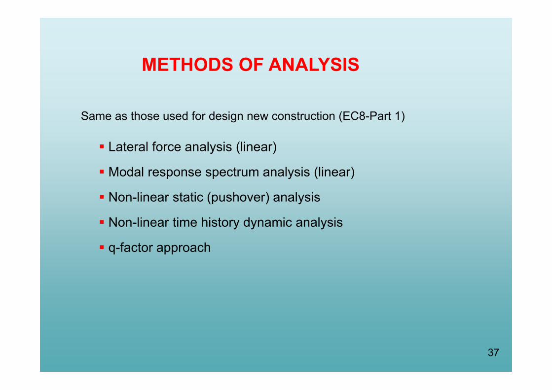
METHODS OF ANALYSIS
Lateral force analysis (linear)
Modal response spectrum analysis (linear)
Non-linear static (pushover) analysis
Non-linear time history dynamic analysis
q-factor approach
Same as those used for design new construction (EC8-Part 1)
38
V3123
123
123
123
V2 V1
V
δδ1 δ2δ3
V2
V1
V3
Capacity curve
Gradual pushing (static horizontal loading) of structure up to failureδ1 δ2 δ3
Points (vi, δi)
V
PERFORMANCE LEVELS
δ
Performance Levels
A BC
damageLight Significant Heavily
(Base shear)
(Top displacement)
39
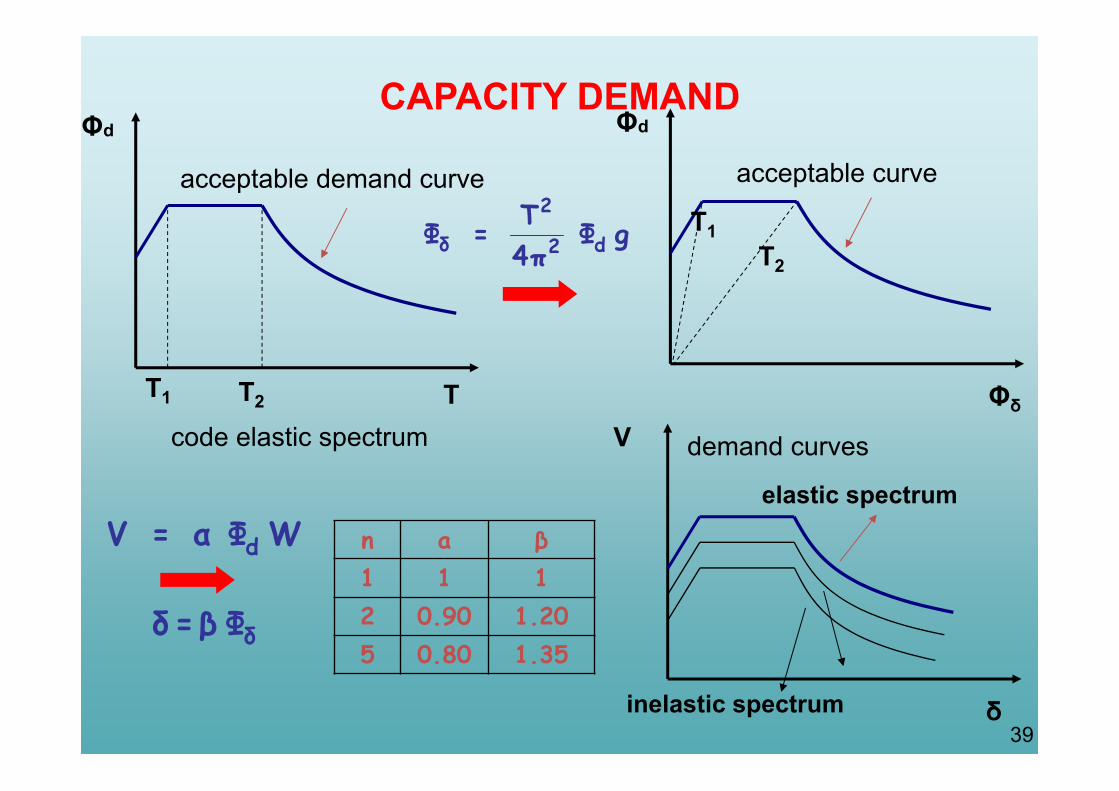
Φd
TT1 T2
Φd
Φδ
T1T2
gΦπ4Τ=Φ d2
2
δ
WΦα=V d
δΦβ=δ
n a β1 1 12 0.90 1.205 0.80 1.35
CAPACITY DEMAND
acceptable curveacceptable demand curve
V
δ
demand curves
elastic spectrum
inelastic spectrum
code elastic spectrum

40
SAFETY VERIFICATIONChecking a Structure’s Capacity
V
δ
Α
Demand Curve(Required Seismic Capacity)
Safe Behaviour
Unsafe behaviour
Sufficient for Level A
Sufficient for Level B
Sufficient for Level C
Insufficient
Α Β
Β CΑ

41
Seismic Strengthening Strategies Methods of Strengthening the Whole
Structure

42
SEISMIC STREGHTENING STRATEGIES
(s) Required seismic capacity
(d) Enhancing strength and stiffness
(b1) Retrofitting local weakness and enhancement of ductility(a) Initial capacity
Displacement
(c) Enhancing strength and ductility
(b2) As (b1) plus some strength increase
Bas
e S
hear
Safe Design
Unsafe Design

43
SEISMIC STRENGHTENIG METHODS
Strength & Stiffness
Strength DuctilityStrength
&Ductility
Add New Walls Steel orConcreteBracing
Adding RCWing Walls
Jackets(a) Infill walls
(b) Externally attached to the structural system
(specific design)
(a) of RC(b) of steel elements
(c) of composite materials

44The relative effectiveness of strengthening

45
Adding Simple Infill
Addition of walls from: a) Unreinforced or reinforced concrete(cast in situ or prefabricated)
b) Unreinforced or reinforced masonry
No specific requirement to connect infill to the existing frame
Modelling of infills by diagonal strut
Low ductility of infill. Recommended m ≤ 1,5
WARNINGAdditional shear forces are induced in the columns and beams of the frame

46
46
Strengthening of existing masonry infills
Reinforced shotcrete concrete layers applied to both sides of the wall
Minimum concrete thickness 50 mm
Minimum reinforcement ratio ρvertical = ρhorizontal = 0,005
Essential to positively connect both sides by bolting through the wall
No need to connect to existing frame as it is an infill
All new construction must be suitably connected to the existing foundation
47
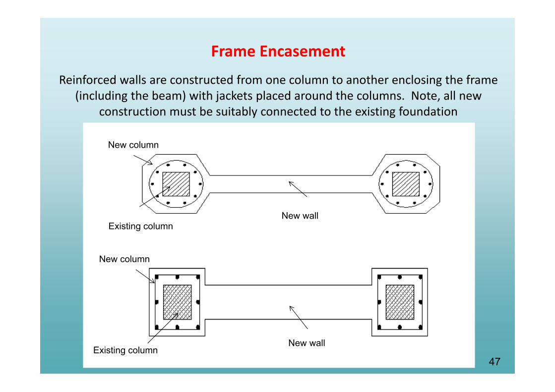
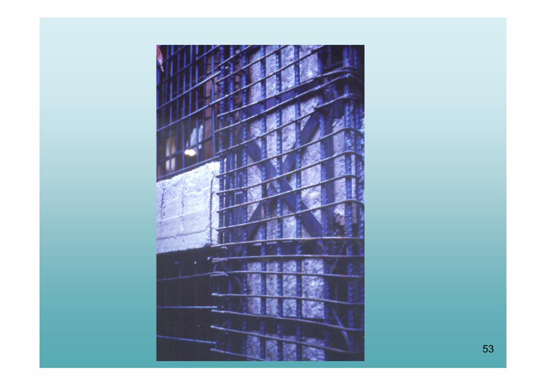
Reinforced walls are constructed from one column to another enclosing the frame (including the beam) with jackets placed around the columns. Note, all new
construction must be suitably connected to the existing foundation
Frame Encasement
New column
Existing columnNew wall
New column
Existing columnNew wall

48
Infilling new shear walls
New wing wallExisting column
Existing column
New wall
Existing columnNew wall
Jacket
Existing column New wing wall
Jacket
Addition of new wing walls

49
Existing vertical element configuration (PLAN)
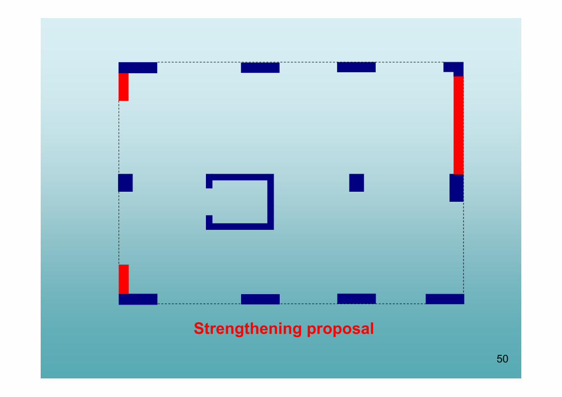
50
Strengthening proposal

51

52
53
54
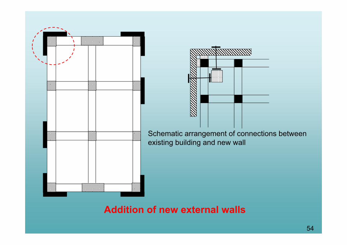
Addition of new external walls
Schematic arrangement of connections between existing building and new wall

55Addition of a bracing system

56

57

58Temporary support and stiffening of the damaged soft floor

59
COMPOSITE ELEMENTS
60
Concrete Steel FRP
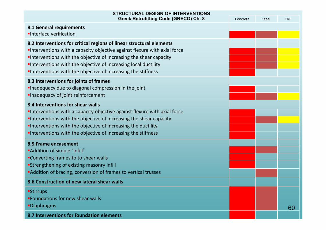
8.1 General requirementsInterface verification
8.2 Interventions for critical regions of linear structural elementsInterventions with a capacity objective against flexure with axial forceInterventions with the objective of increasing the shear capacityInterventions with the objective of increasing local ductilityInterventions with the objective of increasing the stiffness
8.3 Interventions for joints of framesInadequacy due to diagonal compression in the jointInadequacy of joint reinforcement
8.4 Interventions for shear wallsInterventions with a capacity objective against flexure with axial forceInterventions with the objective of increasing the shear capacityInterventions with the objective of increasing the ductilityInterventions with the objective of increasing the stiffness
8.5 Frame encasementAddition of simple “infill”Converting frames to to shear wallsStrengthening of existing masonry infillAddition of bracing, conversion of frames to vertical trusses
8.6 Construction of new lateral shear walls
StirrupsFoundations for new shear wallsDiaphragms
8.7 Interventions for foundation elements
STRUCTURAL DESIGN OF INTERVENTIONSGreek Retrofitting Code (GRECO) Ch. 8
61
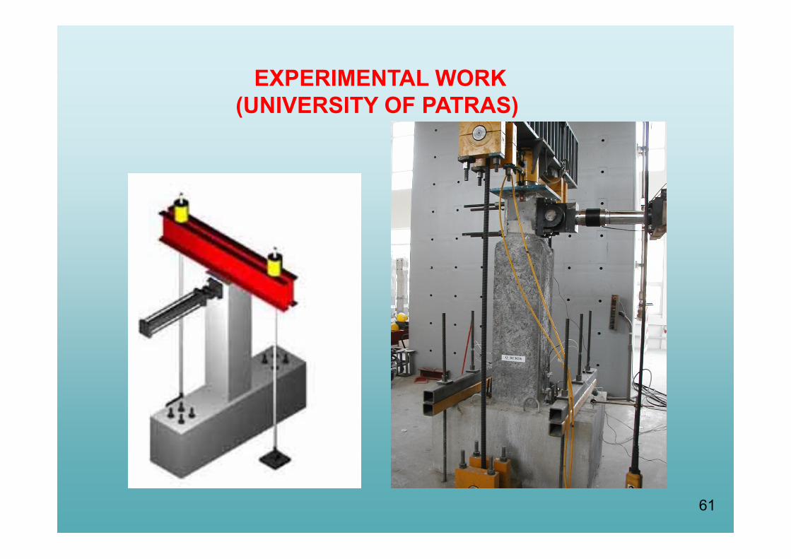
EXPERIMENTAL WORK(UNIVERSITY OF PATRAS)
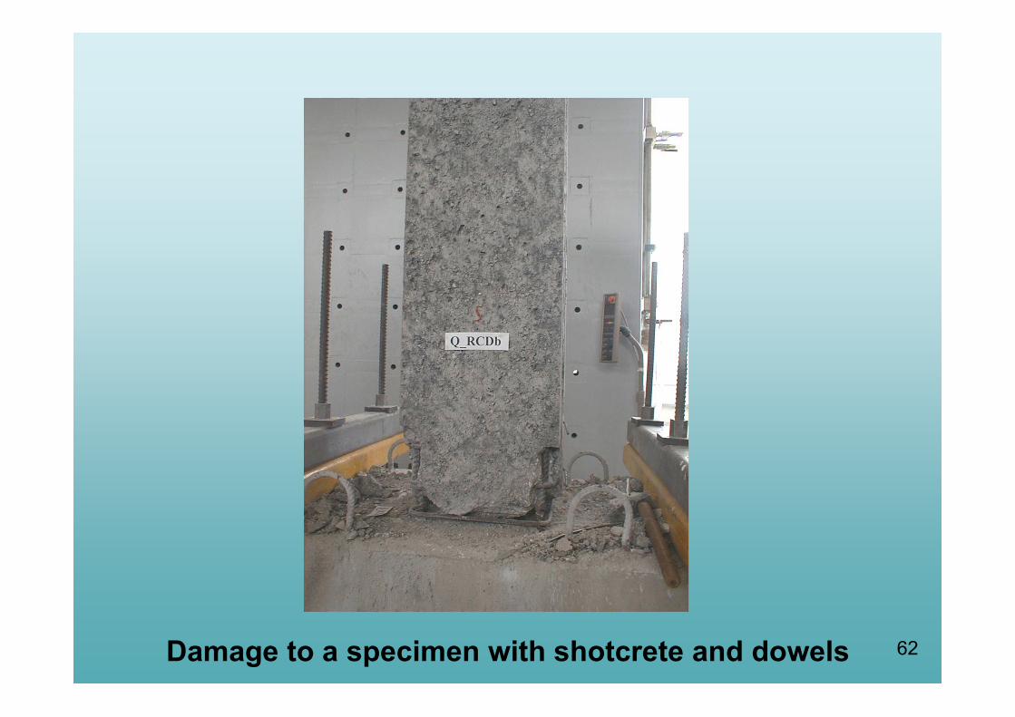
62Damage to a specimen with shotcrete and dowels

6363636363Damage to a specimen with poured concrete, smooth interface without dowels
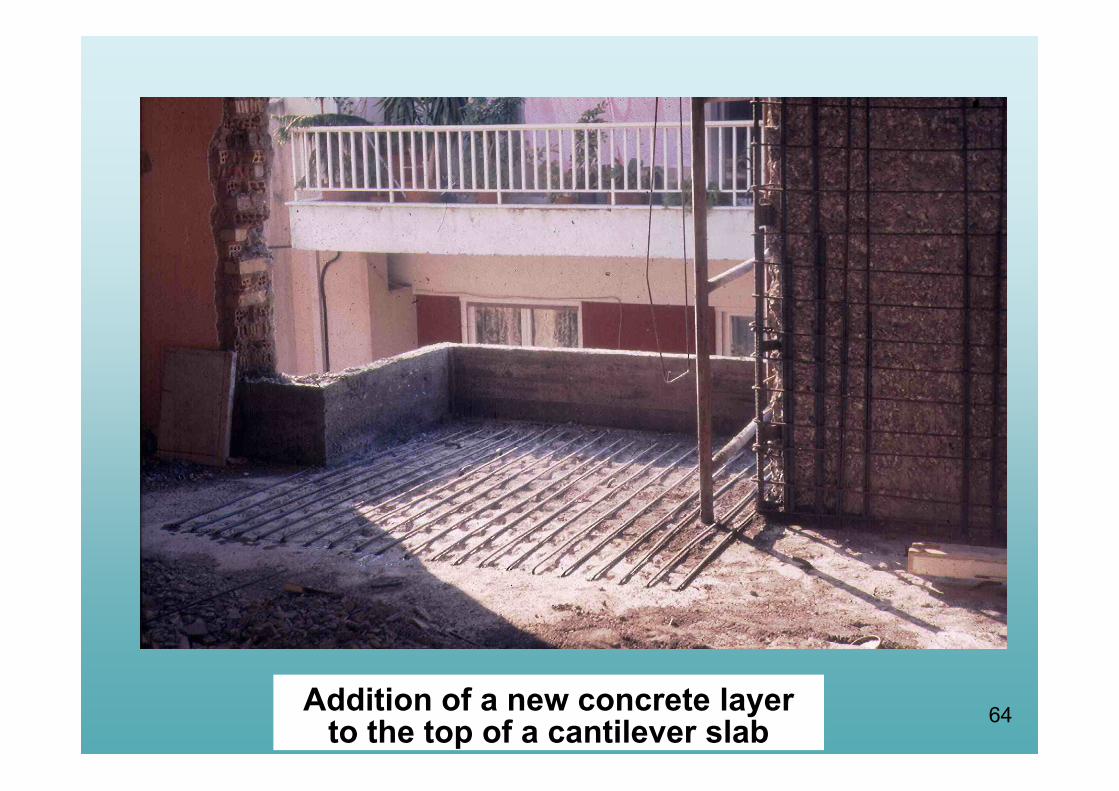
64Addition of a new concrete layer to the top of a cantilever slab

65
Beam strengthened with a new concrete layer
Interface failure due to inadequate anchorage of the new bars at the supports

66
BASIC DESIGN CONSIDERATION
Influence of Interface Connection
Repaired/Strengthened Element
Multi – Phased Element
Composite Element
67
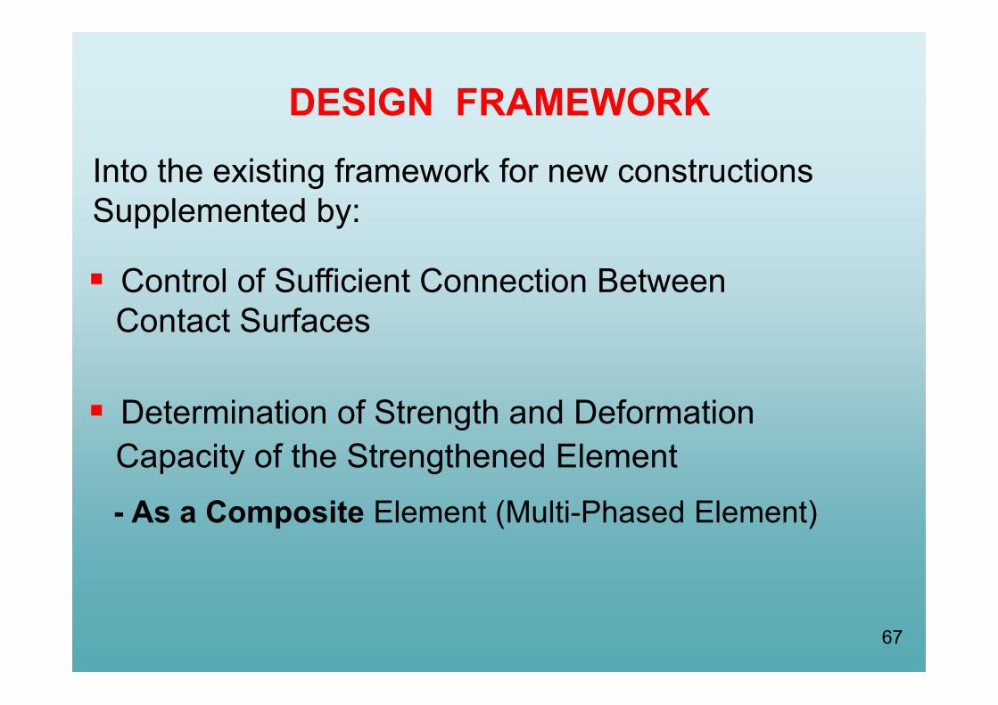
DESIGN FRAMEWORK
Control of Sufficient Connection BetweenContact Surfaces
Determination of Strength and DeformationCapacity of the Strengthened Element- As a Composite Element (Multi-Phased Element)
Into the existing framework for new constructions Supplemented by:
68
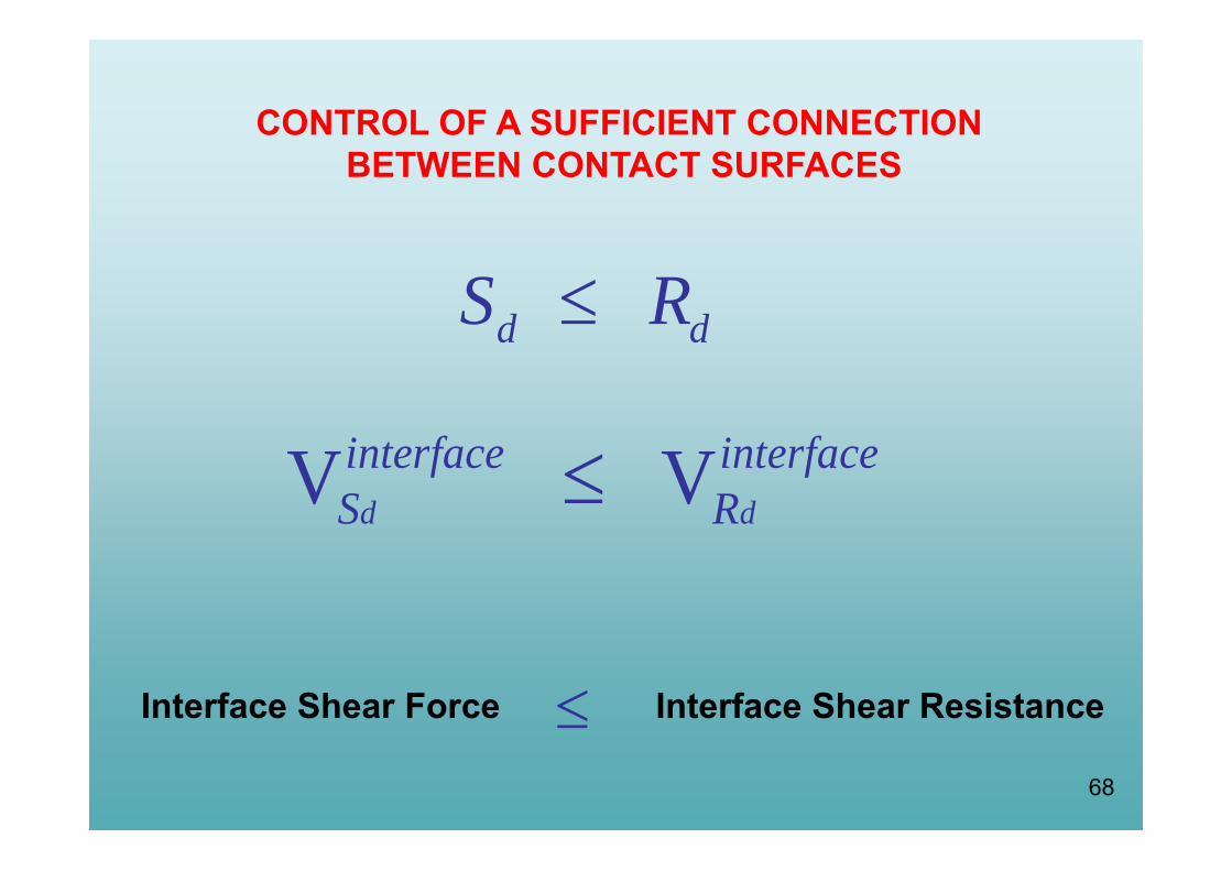
CONTROL OF A SUFFICIENT CONNECTIONBETWEEN CONTACT SURFACES
d dS R
V Vd d
interface interfaceS R
Interface Shear Force Interface Shear Resistance

69
INTERFACE SHEAR FORCES:
i j AB CDV F F interfacei j AB CDV F F interface
(a) strengthening in the tensile zone (b) strengthening in the compressive zone
erfacesdV int

70
Technological guidelines for repairs and
strengthening:
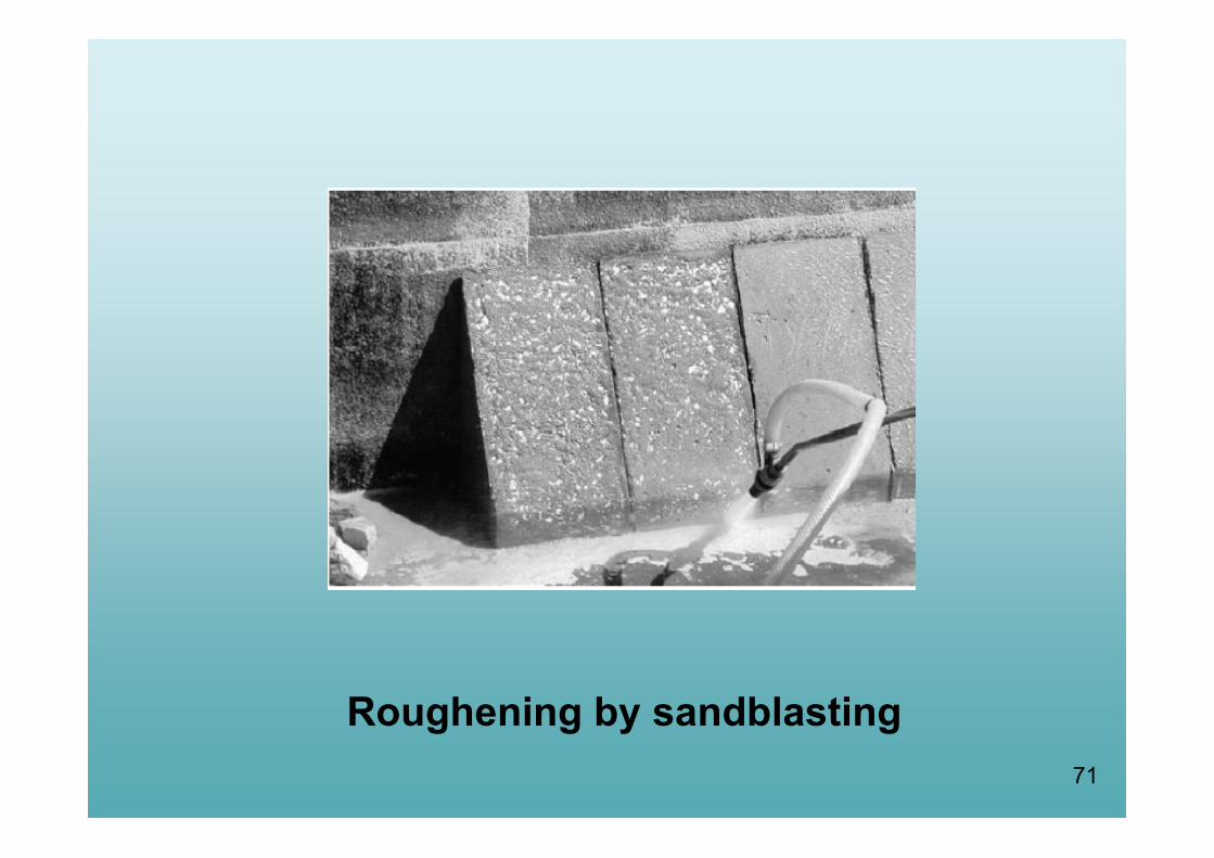
71
Roughening by sandblasting

72
Use of a scabbler to improve frictional resistance by removing the exterior weak skin of the concrete to expose the aggregate
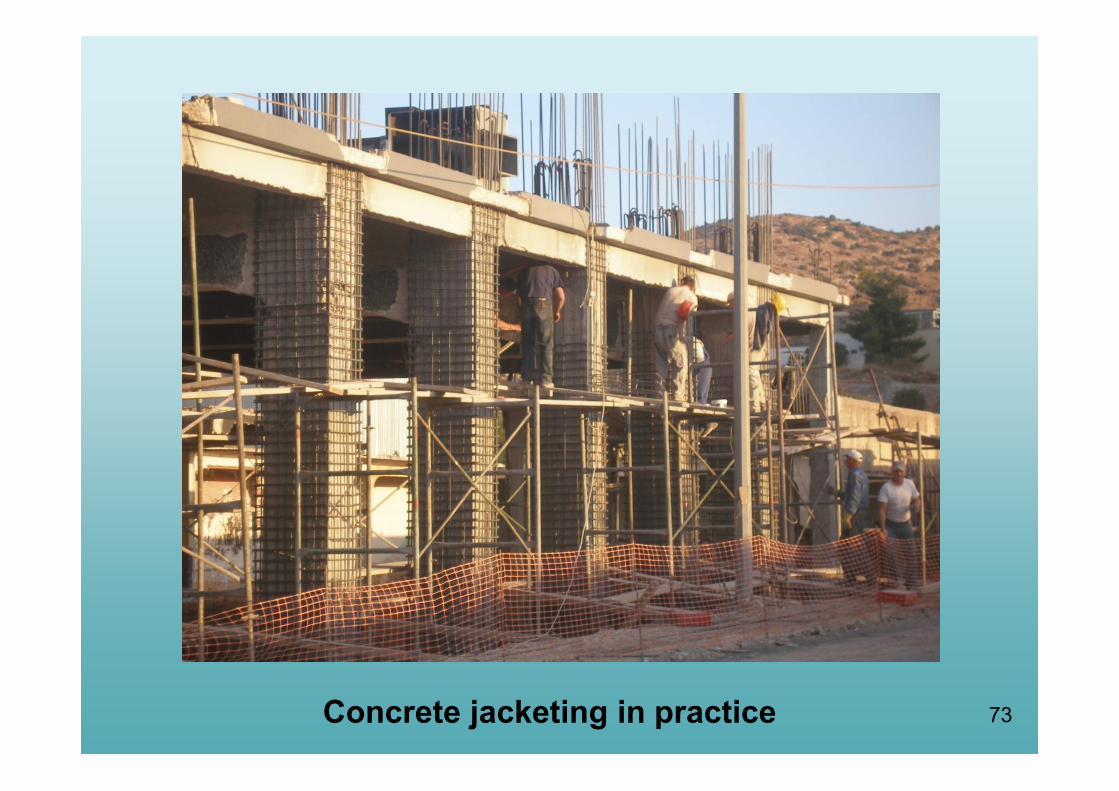
73Concrete jacketing in practice

74

75Total jacket
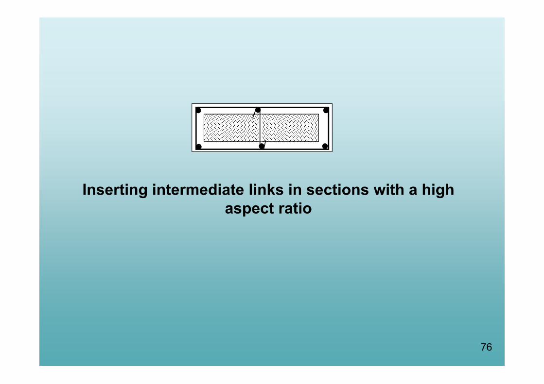
76
Inserting intermediate links in sections with a high aspect ratio
77
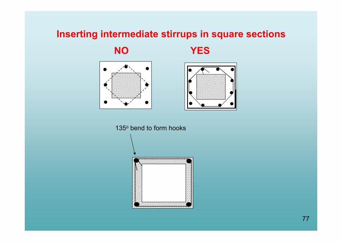
NO YESInserting intermediate stirrups in square sections
135ο bend to form hooks

78Bar buckling due to stirrup ends opening

79Welding of jacket’s stirrup ends
80
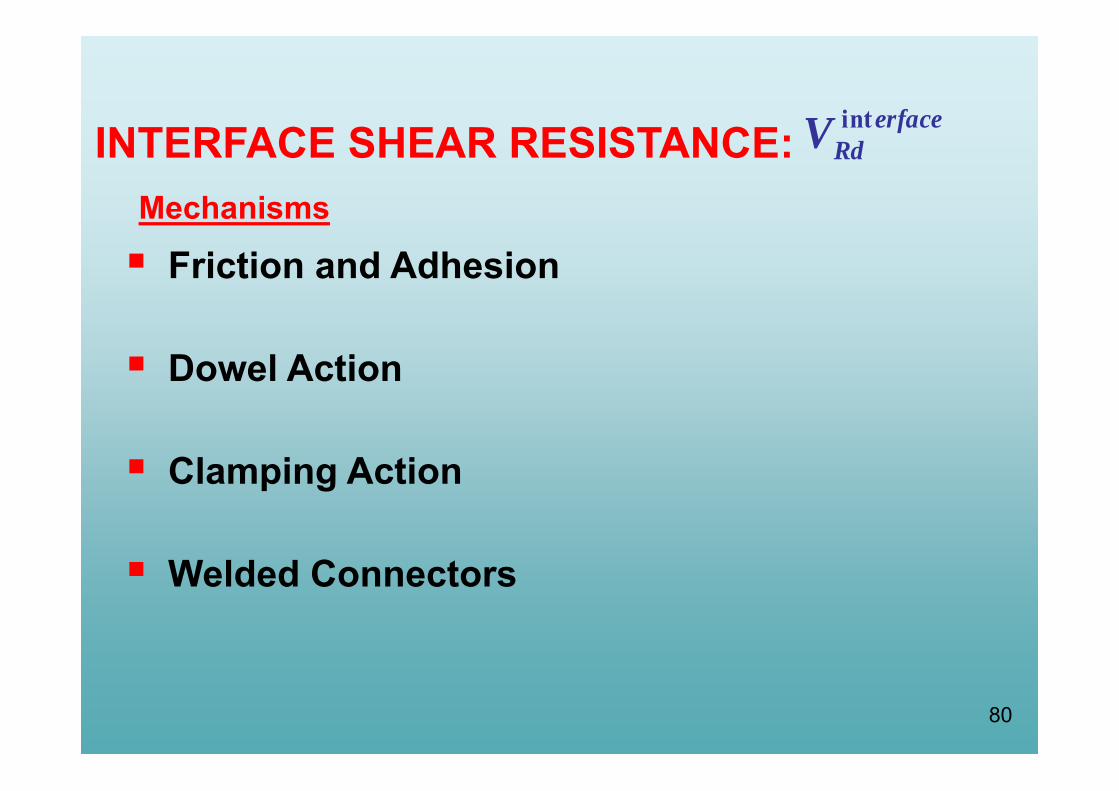
INTERFACE SHEAR RESISTANCE:Mechanisms
erfaceRdV int
Friction and Adhesion
Dowel Action
Clamping Action
Welded Connectors

81
UNREINFORCED INTERFACES
0
1
2
3
4
0 0.1 0.2 0.3 0.4 0.5 0.6
s (mm)
τ (N
/mm
2 )
Concrete-to-concrete adhesion Roughened interface concrete-to-concrete friction
rough interface with adhesion
rough interface without adhesion
smooth interface with adhesion
(CEB Bul. No. 162, 1983)
τ/τfud
(GRECO, 2012)
0 sf
τfud
0.5sfu sfu
30 5 1 14f ff fu
fu fud
s, , s / s
s
0 5 0 81 0 19f f f
fu fud fu
s s, , ,
s s
2 1/3fu c c0.4(f )
82
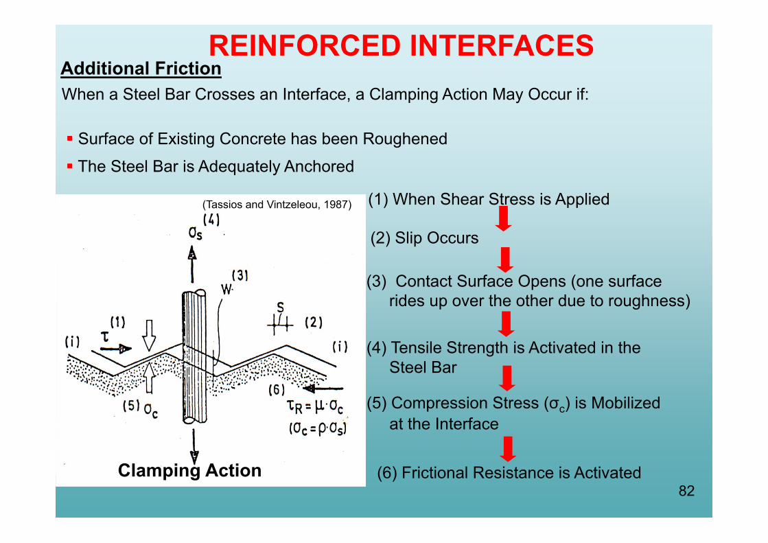
REINFORCED INTERFACES When a Steel Bar Crosses an Interface, a Clamping Action May Occur if:
Surface of Existing Concrete has been Roughened
The Steel Bar is Adequately Anchored
(1) When Shear Stress is Applied
(2) Slip Occurs
(3) Contact Surface Opens (one surfacerides up over the other due to roughness)
(4) Tensile Strength is Activated in the Steel Bar
(5) Compression Stress (σc) is Mobilized at the Interface
(6) Frictional Resistance is Activated
(Tassios and Vintzeleou, 1987)
Additional Friction
Clamping Action
83
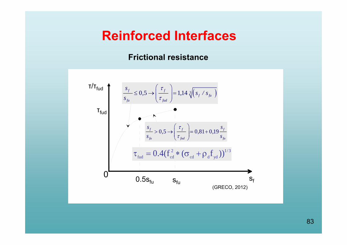
(GRECO, 2012)
0 sf
τfud
0.5sfu sfu
30 5 1 14f ff fu
fu fud
s, , s / s
s
0 5 0 81 0 19f f f
fu fud fu
s s, , ,
s s
2 1/ 3fud cd cd d yd0.4(f ( f ))
τ/τfud
Reinforced Interfaces Frictional resistance

84
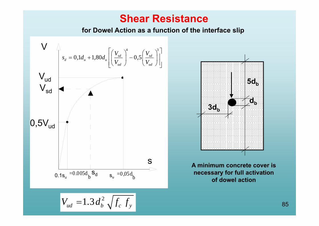
V
Dowel action
Reinforced Interfaces
85
6db
5db
3dbdb
du =0,1db0,1du0.1du=0.005db du=0,05db
s
V
VudVsd
0,5Vud
sd
4 3
0 1 1 80 0 5sd sdd u u
ud ud
V Vs , d , d ,
V V
0.1su su
Shear Resistancefor Dowel Action as a function of the interface slip
A minimum concrete cover is necessary for full activation
of dowel action
21 3ud b c yV . d f f
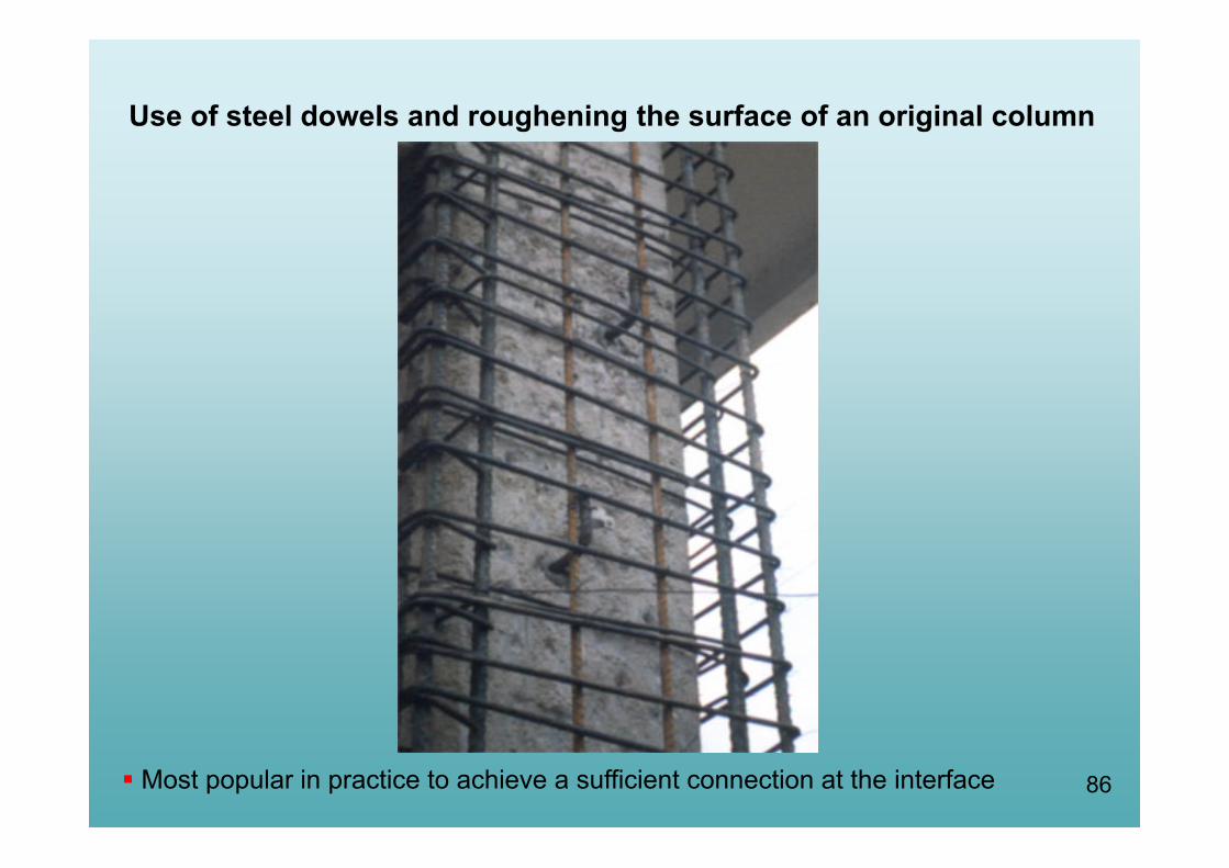
86
Use of steel dowels and roughening the surface of an original column
Most popular in practice to achieve a sufficient connection at the interface

87
Reinforced InterfacesBent Connecting Steel Bars

88
Bent Bar Model
sb s ybs
s f2h
and
s sb s s sy sb ybT A E (s / 2h ) T 2A f
When occur at the interface one leg of the bent bar is elongated by the other is shortened
2/ss
Tensile and Compressive Leg Stresses are mobilized:
Force is Transferred between Reinforcements:
s
s
old barnew bar
hs
Ts
Ts
(Tassios, 2004)
sbss
s / 2 s2h2h

89
0.0
0.2
0.4
0.6
0.8
1.0
1.2
0.0 0.1 0.2 0.3 0.4 0.5 0.6 0.7 0.8 0.9 1.0 s (mm)
T s/T
sy
hs = 60 mmhs = 120 mm
Mechanism is mobilized for very small Slippage
Force Transferred – Interface Slippage
ybsbsy fAT 2
90
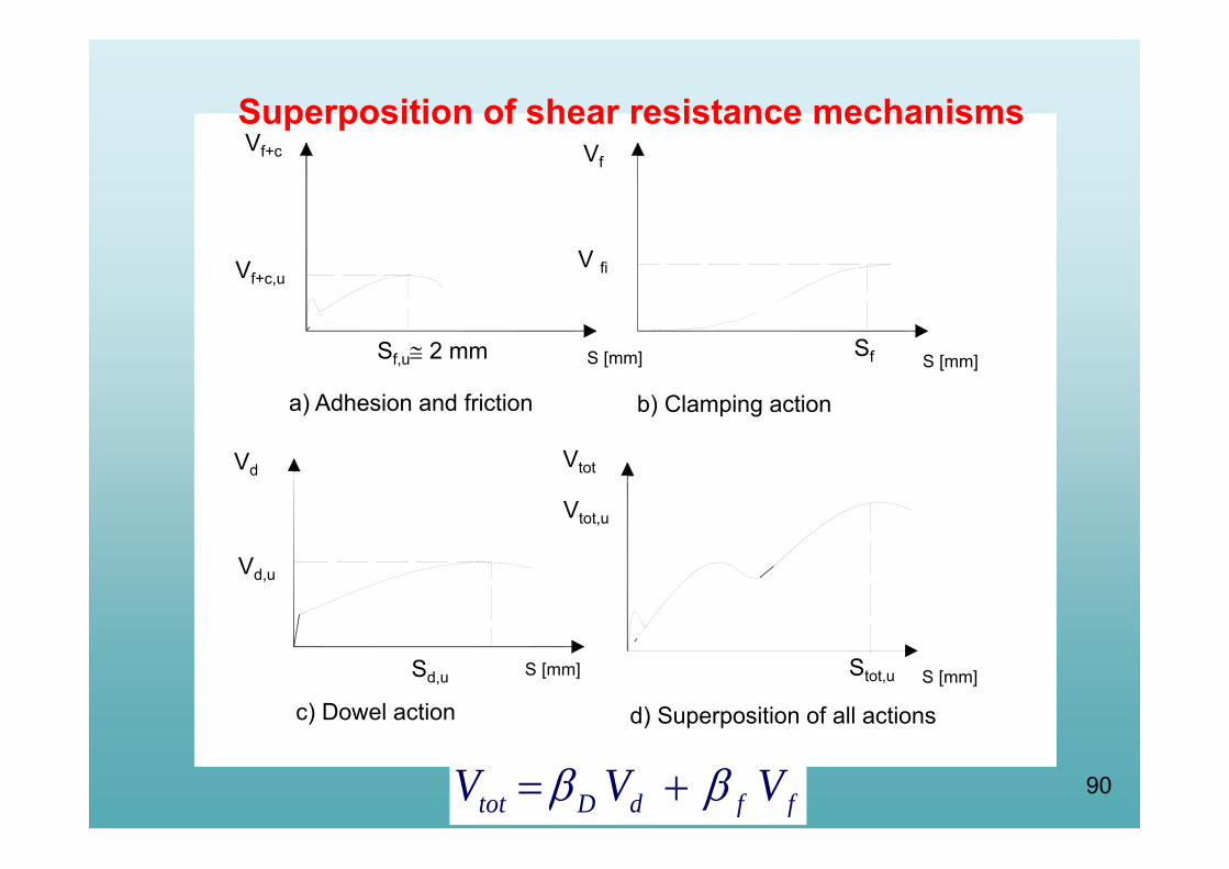
b) Clamping action
Vf+c,u
Sd,u S [mm] S [mm]
Vf+c
Sf,u 2 mm S [mm]
Vf
S [mm]
V fi
Sf
Vd,u
a) Adhesion and friction
c) Dowel action d) Superposition of all actions
Vd
Vtot,u
Stot,u
Vtot
Superposition of shear resistance mechanisms
tot D d f fV V V

91
P
Full interaction
Partial interaction
Independent action
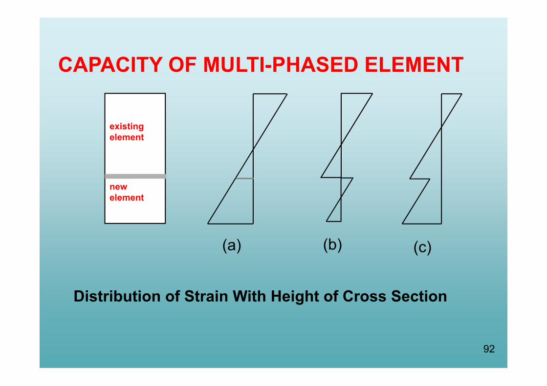
92
Distribution of Strain With Height of Cross Section
CAPACITY OF MULTI-PHASED ELEMENT
existingelement
newelement
(a) (b) (c)

93Possible strain and stress distributions

94
F
δ
Fy,μFy,ε
Monolithic Element
Strengthened Element
Fres,μ
Fres,ε
δy,μδy,ε δu,μδu,ε
Κμ
Κε
y,εr
y,μ
FΚ =F
y,εδy y,μ
δΚ =δεκμ
ΚΚ =Κu,ε
δu u,μ
δΚ =δ
CAPACITY CURVES
Deformation
Act
ion
effe
ct
95
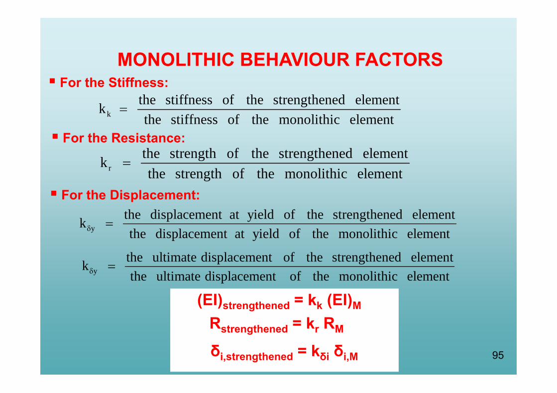
MONOLITHIC BEHAVIOUR FACTORS For the Stiffness:
kthe stiffness of the strengthened elementkthe stiffness of the monolithic element
For the Resistance:
rthe strength of the strengthened elementkthe strength of the monolithic element
(EI)strengthened = kk (EI)M
Rstrengthened = kr RM
For the Displacement:
ythe displacement at yield of the strengthened elementkthe displacement at yield of the monolithic element
ythe ultimate displacement of the strengthened elementkthe ultimate displacement of the monolithic element
δi,strengthened = kδi δi,M
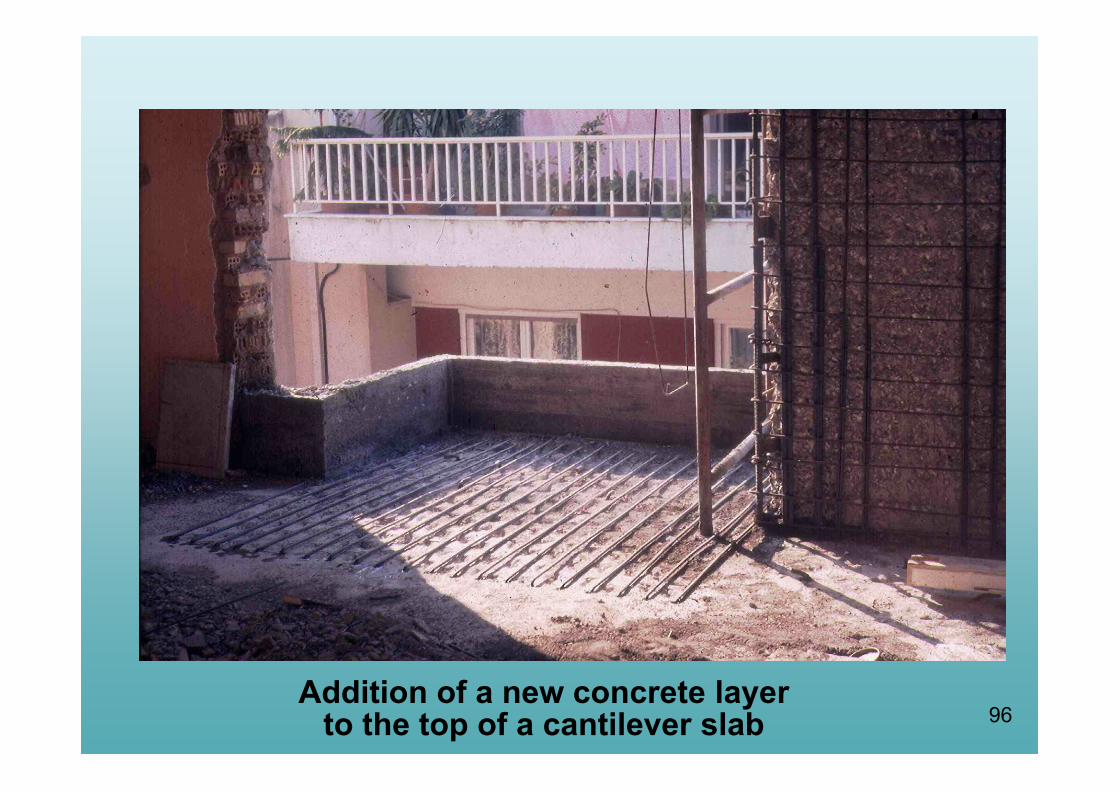
96Addition of a new concrete layer
to the top of a cantilever slab

97
Monolithic Factors Approximations according to G.C.S.I.
For slabs:
kk = 0,85 kr = 0,95 kθy = 1,15 kθu = 0,85
For other elements:
kk = 0,80 kr = 0,85 kθy = 1,25 kθu = 0,75
For concrete jackets:
kk = 0,80 kr = 0,90 kθy = 1,25 kθu = 0,80
98
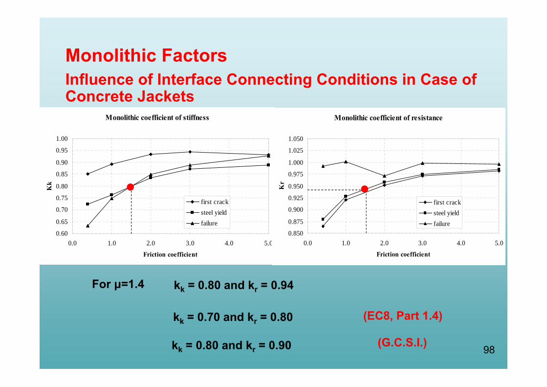
kk = 0.80 and kr = 0.94
kk = 0.70 and kr = 0.80 (EC8, Part 1.4)
Monolithic FactorsInfluence of Interface Connecting Conditions in Case of Concrete Jackets
Monolithic coefficient of stiffness
0.60
0.65
0.70
0.75
0.80
0.85
0.90
0.95
1.00
0.0 1.0 2.0 3.0 4.0 5.0
Friction coefficient
Kk
first cracksteel yieldfailure
Monolithic coefficient of resistance
0.850
0.875
0.900
0.925
0.950
0.975
1.000
1.025
1.050
0.0 1.0 2.0 3.0 4.0 5.0
Friction coefficient
Kr
first cracksteel yieldfailure
For μ=1.4
kk = 0.80 and kr = 0.90 (G.C.S.I.)