stepper motor control - teqipiitk.in · stepper motor a stepper motor is an electromagnetic...
TRANSCRIPT

Stepper Motor control(Manual, Arduino and LabVIEW based)
Anjali V. KulkarniCentre for Mechatronics
IIT Kanpur

2
Stepper MotorA stepper motor is an electromagnetic
incremental actuator which converts electrical pulse to mechanical movements.
It is a brushless, synchronous electric motor that can divide a full rotation into number of steps.
The motor’s position can be controlled accurately without any feedback mechanism.
AdvantagesThe motor has full torque at standstill. Precise positioning and repeatabilityAccuracy of 3 – 5% of a step, non cumulativeExcellent response to starting, stopping and reversing.Reliable operation as no contact brushes in the motorLong lifeOpen-loop and cost effective controlLow speed synchronous rotation with a load that is
directly coupled to the shaft is possible. A wide range of rotational speeds can be realized as the
speed is proportional to the frequency of the input pulses
ApplicationsIndustrial Machines –used in automotive gauges
and machine tooling, automated production equipment, etc.
Security – new surveillance products for the security industry.
Medical –used inside medical scanners, samplers, digital dental photography, fluid pumps, respirators and blood analysis machinery, etc.
Consumer Electronics –in cameras for automatic digital camera focus and zoom functions, in printers, etc.
And many others…
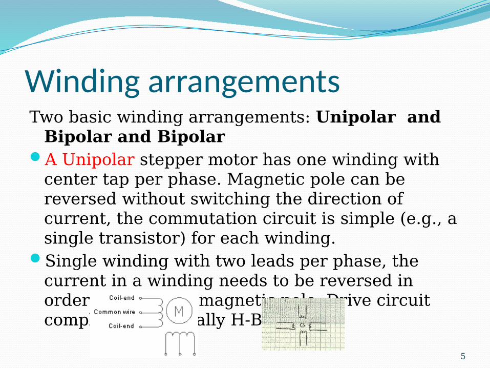
Winding arrangementsTwo basic winding arrangements: Unipolar and
Bipolar and BipolarA Unipolar stepper motor has one winding with
center tap per phase. Magnetic pole can be reversed without switching the direction of current, the commutation circuit is simple (e.g., a single transistor) for each winding.
Single winding with two leads per phase, the current in a winding needs to be reversed in order to reverse a magnetic pole, Drive circuit complicated, typically H-Bridge
5
6
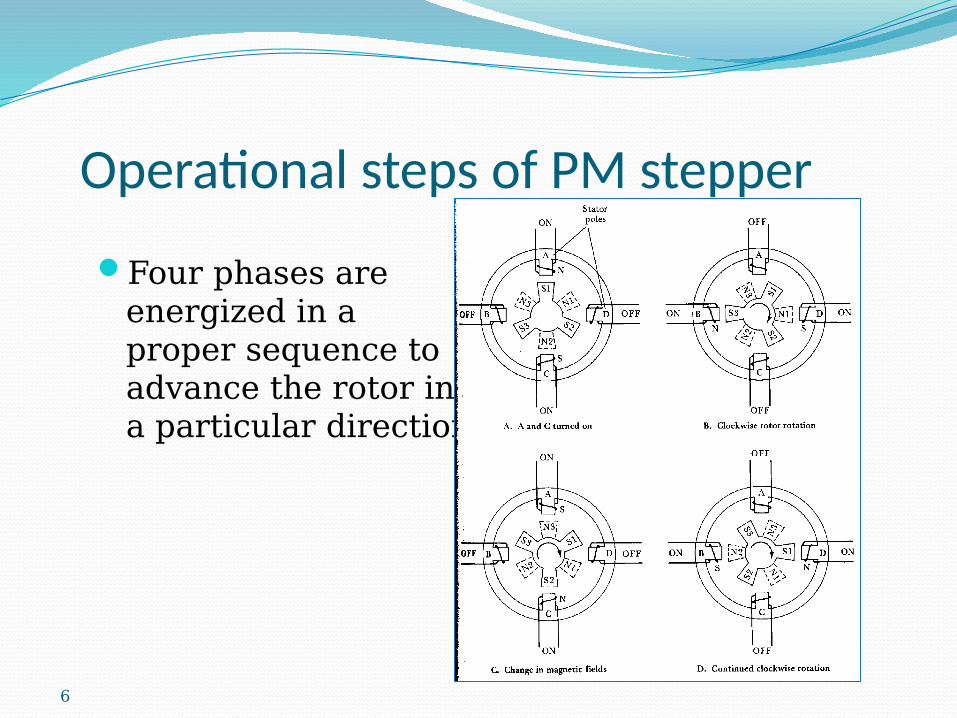
Operational steps of PM stepper
Four phases are energized in a proper sequence to advance the rotor in a particular direction
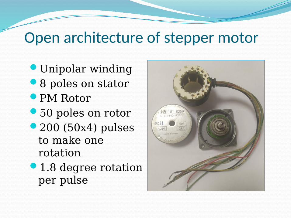
Open architecture of stepper motor
Unipolar winding8 poles on statorPM Rotor50 poles on rotor200 (50x4) pulses
to make one rotation
1.8 degree rotation per pulse
Stepper motor drive SM performance depends on the drive
circuit. Torque curves may be extended to greater speeds if the stator poles can be reversed more quickly. The limiting factor in doing so is the winding inductance.
To overcome the inductance and switch the windings quickly, one must increase the drive voltage within the permissible limit to withstand current that these high voltages may otherwise induce.
8

Driving strategiesFull step drive (two phases on): This is the usual
method for full step driving the motor. The motor will have full rated torque.
Half stepping (single phase is on): When half stepping, the drive alternates between two phases on and a single phase on. This increases the angular resolution, the motor has less torque (approx 70%) at the half step position, this may be mitigated by increasing the current in the active winding to compensate.
Microstepping: It is often "sine cosine microstepping" in which the winding current approximates a sinusoidal AC waveform. The functioning becomes very smooth and resolution is further increased.
9
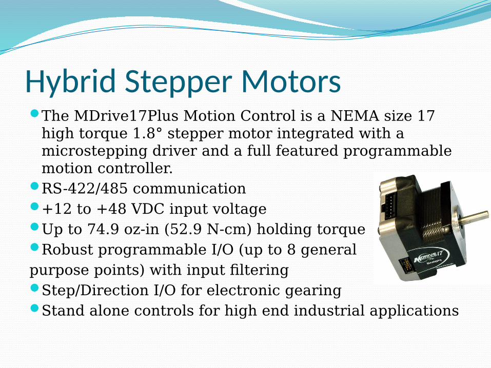
Hybrid Stepper MotorsThe MDrive17Plus Motion Control is a NEMA size 17
high torque 1.8° stepper motor integrated with a microstepping driver and a full featured programmable motion controller.
RS-422/485 communication+12 to +48 VDC input voltageUp to 74.9 oz-in (52.9 N-cm) holding torqueRobust programmable I/O (up to 8 general purpose points) with input filteringStep/Direction I/O for electronic gearing Stand alone controls for high end industrial applications
11
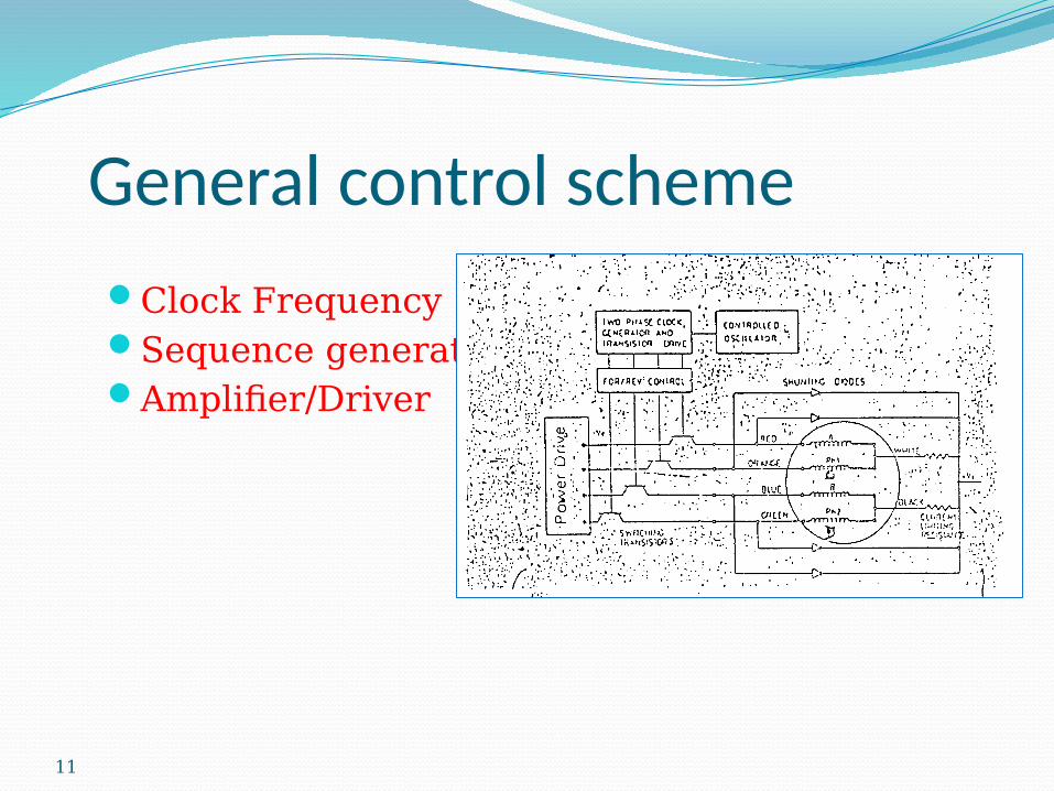
General control scheme
Clock FrequencySequence generatorAmplifier/Driver

Experiments with Different Control strategies1. Manual, 555 timer based 2. Arduino based3. LabVIEW based using motion control card
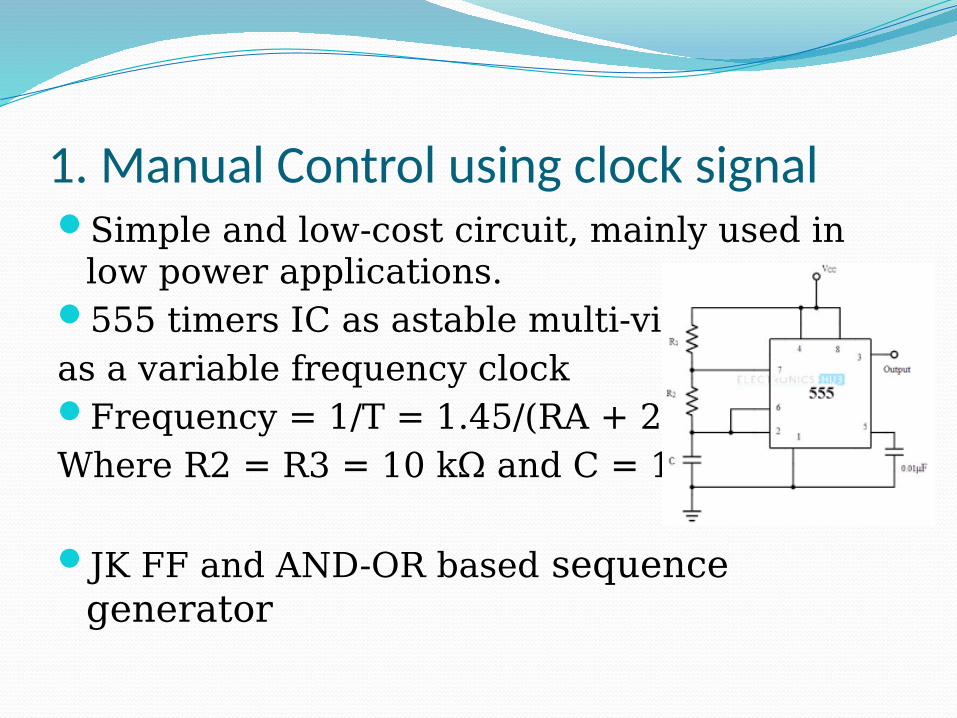
1. Manual Control using clock signalSimple and low-cost circuit, mainly used in
low power applications. 555 timers IC as astable multi-vibrator as a variable frequency clockFrequency = 1/T = 1.45/(RA + 2RB)C Where R2 = R3 = 10 kΩ and C = 100 µF.
JK FF and AND-OR based sequence generator
14
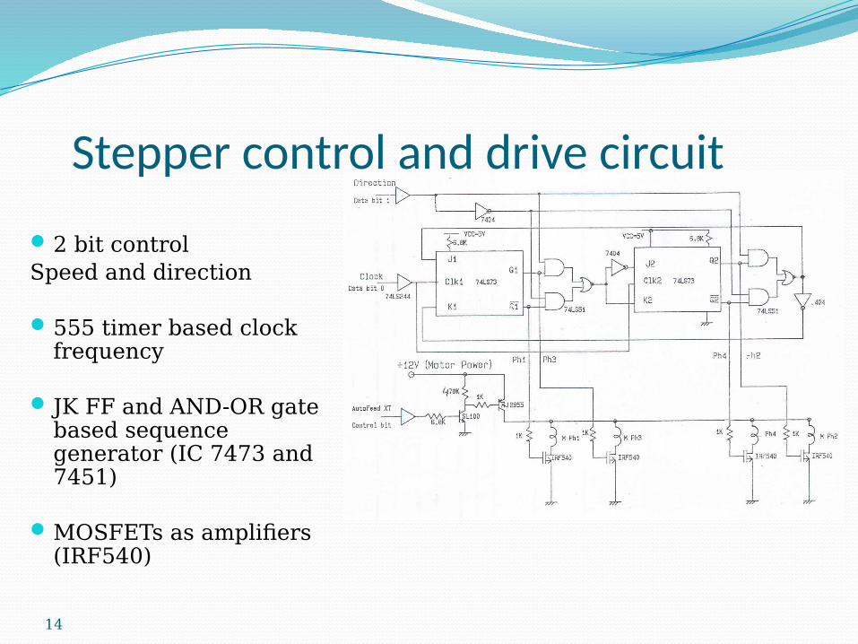
Stepper control and drive circuit
2 bit controlSpeed and direction
555 timer based clock frequency
JK FF and AND-OR gate based sequence generator (IC 7473 and 7451)
MOSFETs as amplifiers (IRF540)
Experimental ProcedureSelect the direction
bit,Vary the clock
frequency, study the waveforms at different test points in the circuit using oscilloscope at • 555 timer output,• Sequencer outputs &• MOSFET output
Use of Oscilloscope as the measuring equipment
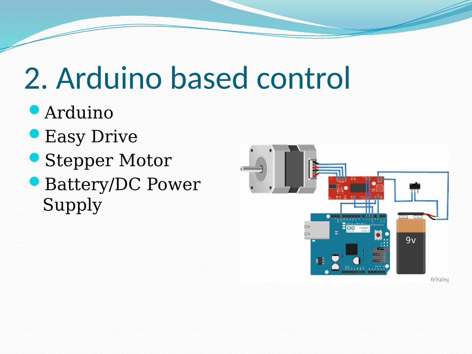
2. Arduino based controlArduinoEasy DriveStepper MotorBattery/DC Power
Supply

Basic Arduino setup with Easy Driver Features of Easy Driver (V44A3967) ±750 mA, 30 V output rating 3.0 to 5.5 V logic supply voltage range Mixed, fast, and slow current-decay modes Internal UVLO and thermal shutdown
circuitry Crossover-current protection Connect motor's four wires to the Easy
Driver (note the proper coil connections), connect a power supply of 12V to the Power In pins, and connect Arduino's GND, pin 8 and pin 9 to the Easy Driver.

Control Program in ‘C’ LanguagePin function DeclarationVariable DeclarationSerial Interface SettingsMain Loop
User Input AcquisitionWrite ‘LOW’ and ‘ HIGH’ on Pin 2 (Move the
motor in Forward or Reverse Directions) with the set Delay Time
Experimental ProcedureStudy the hardwareStudy the control programChange parameters and see the motor
response
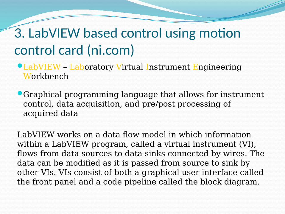
3. LabVIEW based control using motion control card (ni.com)LabVIEW – Laboratory Virtual Instrument Engineering
Workbench
Graphical programming language that allows for instrument control, data acquisition, and pre/post processing of acquired data
LabVIEW works on a data flow model in which information within a LabVIEW program, called a virtual instrument (VI), flows from data sources to data sinks connected by wires. The data can be modified as it is passed from source to sink by other VIs. VIs consist of both a graphical user interface called the front panel and a code pipeline called the block diagram.
A VI has three main parts:The front panel: an interactive user interface
of a VI, so named because it simulates the front panel of a physical instrument.
The block (or wiring) diagram: It is the VI’s source code, constructed in LabVIEW’s graphical programming language, It is the actual executable program.
Icon/connector
NI-MAX (Measurement & Automation Explorer )NI provides Measurement & Automation
Explorer (MAX), a graphical user interface, to configure instrument drivers. MAX is usually installed with one of the NI application development
It provides access to NI CAN, DAQ, FieldPoint, GPIB, IMAQ, IVI, Modular Instruments, Motion, NI Switch Executive, VI Logger, VISA, and VXI devices.
MAX is used to: Configure NI’s hardware and softwareBack up or replicate configuration dataCreate and edit channels, tasks, interfaces,
scales, and VI’sExecute system diagnostics and run test
panelsView devices and instruments connected to
systemUpdate NI software.
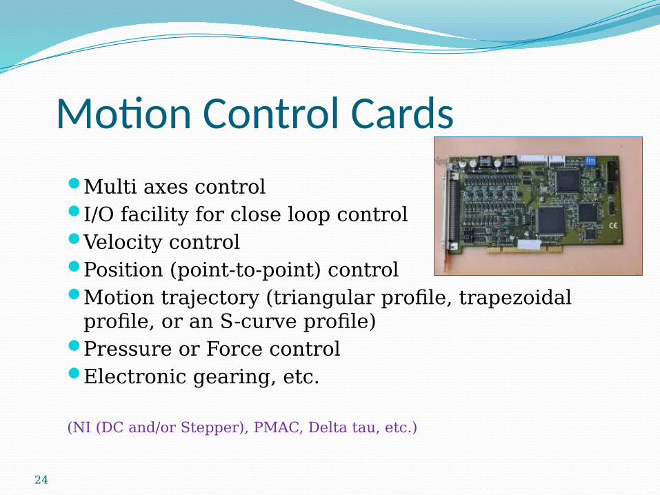
Motion Control Cards
Multi axes controlI/O facility for close loop controlVelocity controlPosition (point-to-point) controlMotion trajectory (triangular profile, trapezoidal
profile, or an S-curve profile)Pressure or Force controlElectronic gearing, etc.
(NI (DC and/or Stepper), PMAC, Delta tau, etc.)
24

NI 7358 Motion controllerThe NI 7358 controller is a combination of servo and
stepper motor controller for PXI, Compact PCI, and PCI bus computers.
Fully-programmable motion control for up to eight independent axes of motion.
Coordinated motion is supported through multi-dimensional coordinate spaces.
Each axis provides dedicated motion I/O for limit and home switches and additional I/O for general-purpose functions.
The external motion and digital I/O connectors on the NI 7358 controller are high-density, 68-pin female VHDCI connectors.

NI UMI -7774
NI UMI -7774 is a 4-Axis Universal Motion Interface as seen in Figure
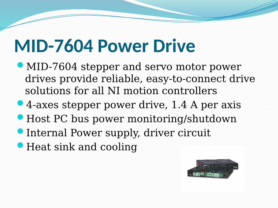
MID-7604 Power DriveMID-7604 stepper and servo motor power
drives provide reliable, easy-to-connect drive solutions for all NI motion controllers
4-axes stepper power drive, 1.4 A per axisHost PC bus power monitoring/shutdownInternal Power supply, driver circuit Heat sink and cooling

Motor Control Hardware Configuration
28

Experimental ProcedureNI MAX will be used to drive stepper motorConfiguration parameter settings:
InitializeStepper/ServoAxis NumberSpeedPosition, etc.To study the working of stepper motor.
